march 21, 2014 workshop on fpgas for high-energy physics single-event effects testing and the xilinx...
TRANSCRIPT

March 21, 2014
Workshop on FPGAs for High-Energy PhysicsWorkshop on FPGAs for High-Energy Physics
Single-Event Effects Testing
and the
Xilinx Radiation Test Consortium
presenter: Gary Swift

SEE Testing & the XRTC Slide 2Page 2
Overview
• SEE Testing for Space– Accelerated AND Accelerator-based Testing– Purpose
• On-orbit rate• Fail signatures and design level mitigation
• XRTC (Xilinx Radiation Test Consortium)– Voluntary membership– Maximize Leveraging– Test Campaign Phases:
• Static • Dynamic• Mitigation
– Beam and/or Fault Injection Common Setup

SEE Testing & the XRTC Slide 3MAPLD Seminar – Sept. 25, 2006
SEE testing is extremely easy.
1. It’s simply counting
2. Only two things to count:• Number of upsets• Total beam fluence
3. The facility counts the beam for you.
SEE Testing’s Basic Principle
SEE Testing & the XRTC Slide 4Short Course – April 22, 2010
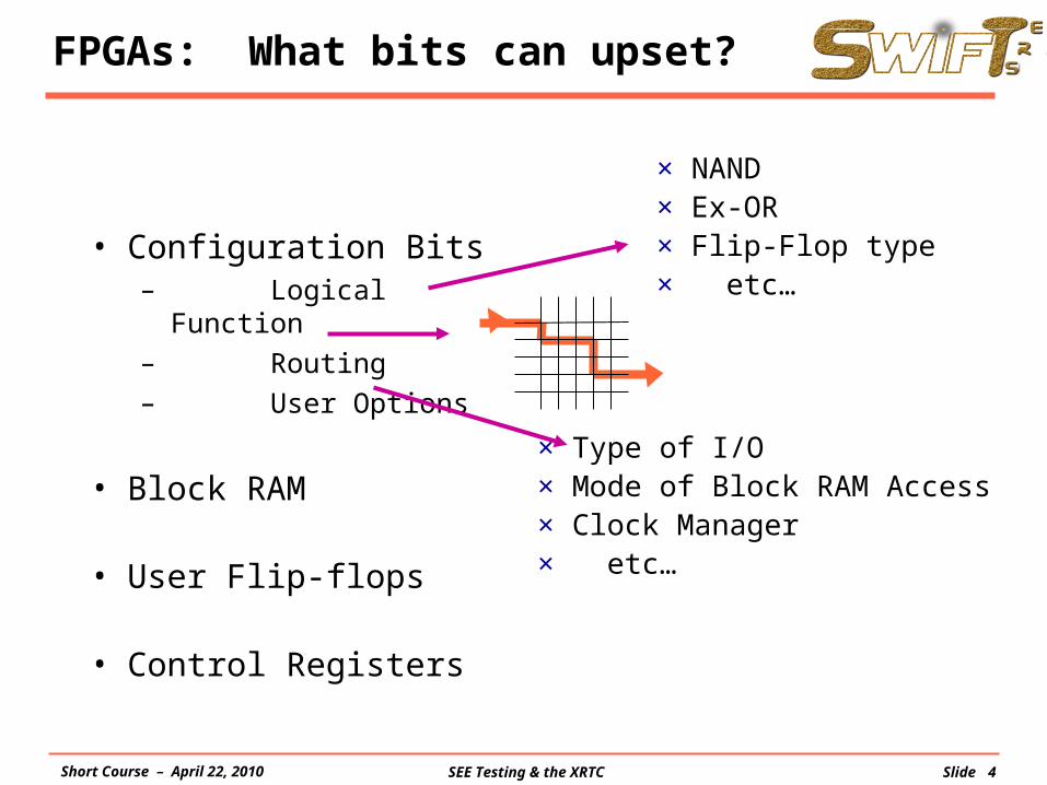
FPGAs: What bits can upset?
• Configuration Bits– Logical
Function– Routing– User Options
• Block RAM
• User Flip-flops
• Control Registers
× Type of I/O× Mode of Block RAM Access× Clock Manager× etc…
× NAND× Ex-OR× Flip-Flop type× etc…

SEE Testing & the XRTC Slide 5MAPLD Seminar – Sept. 25, 2006
SEE Testing Is Hard
Difficult to do
High-Energy Accelerator• Beam costs ~ $1000/hr• Travel & shipping add extra costs• Portable test fixtures and control systems
Test Development
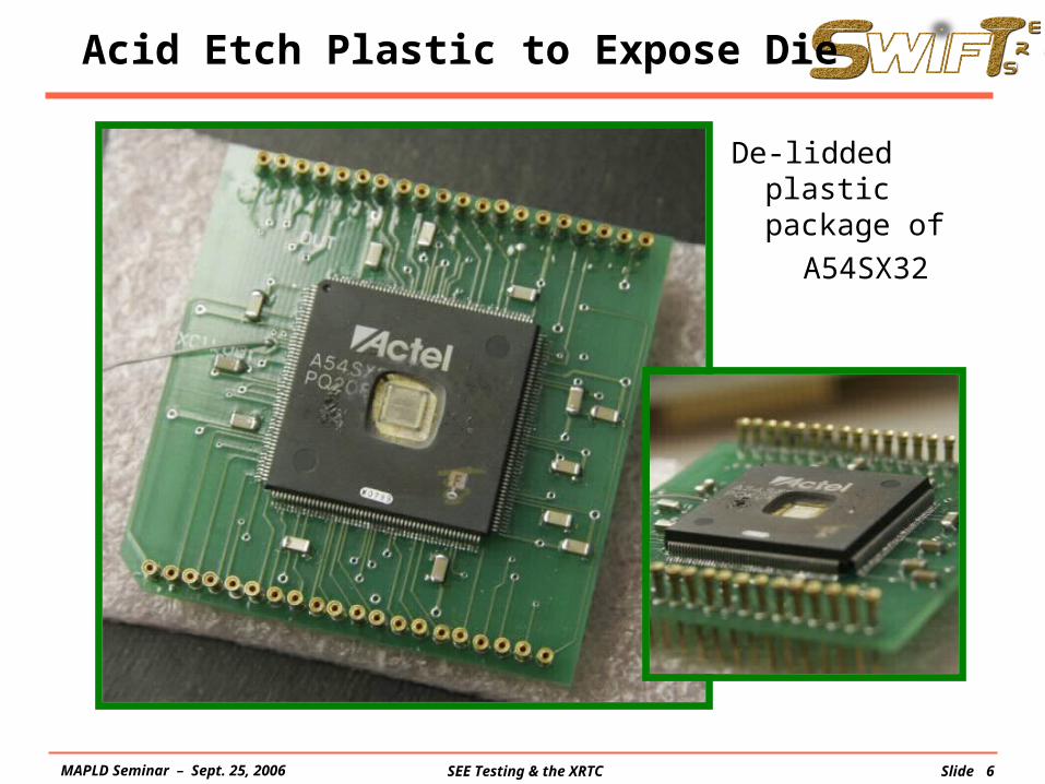
Special Problems• Part De-lidding• In Vacuum Operation
SEE Testing & the XRTC Slide 6MAPLD Seminar – Sept. 25, 2006
Acid Etch Plastic to Expose Die
De-lidded plastic package of
A54SX32

SEE Testing & the XRTC Slide 7MAPLD Seminar – Sept. 25, 2006
Preparation: Thinning Flip-Chip
Technician thins DUT backside

SEE Testing & the XRTC Slide 8MAPLD Seminar – Sept. 25, 2006
Space Upset Rates – Three Inputs
• Measure vs. LET – Testing done at high-energy
accelerator– Cross-section determined
from circuit response
• Determine Sensitive Volume– Requires assumptions about
device construction– Used to determine effect of
ions that strike the device at an angle
• Integrate with LET Spectrum
LET
Measured Cross Section
LET
dN
dE
Particle LET Spectrum
ERROR RATE
Sensitive Volume
σ
1 10 100 0.1 1 10 100

SEE Testing & the XRTC Slide 9Short Course – April 22, 2010
Prediction vs. Actual
Example: Rovers Going to Mars - Pyro Control Board
0
5
10
15
20
25
30
0 50 100 150Days after Launch
# of
Ups
ets
predictedMER-AMER-B Nov. 23
MER-B
Nov. 23MER-A
Oct. 28MER-A
Oct. 28MER-B
Xilinx XQR4062XL (four in each)

SEE Testing & the XRTC Slide 10MAPLD Seminar – Sept. 25, 2006
Lots of Interest Lots of Leveraging
Xilinx, Inc. and JPL started partnering on tests
and soon had to form the Radiation Test Consortium
Boeing Satellite Systems
SEAKR Engineering

SEE Testing & the XRTC Slide 11Short Course – April 22, 2010
XRTC Test Infrastructure
Capturing detailed strip charts allows experiment to be “re-played” for smarter signature identification and later analysis and re-analysis.

SEE Testing & the XRTC Slide 12
Example – Strip Chart of Irradiation
…
…

SEE Testing & the XRTC Slide 13Page 13
0th generation motherboard
Virtex-2 Virtex-IIpro Virtex-4 Virtex-5
XRTC Motherboard History
2000
Xilinx Radiation Test Consortium
2001 2002 2003 2004 2005 2006 2007 2008 2009 2010
JPL & Xilinx partner up
Consortiumformation
1st AnnualMeeting
2nd generation motherboard
3rd generation motherboard
1st generation motherboard
2011 2012

SEE Testing & the XRTC Slide 14MAPLD Seminar – Sept. 25, 2006
BOTH Fault Injection & Irradiation
• Dynamic Test Setup at Texas A&M Cyclotron
Inside target room
Configuration Monitor/ Strip Chart
Functional Monitor/ Strip Chart
SEAKR-built DUT Board - XQR2V6000 in beam
BEAM
Thinned DUT

SEE Testing & the XRTC Slide 15MAPLD Seminar – Sept. 25, 2006
Backside
Lots of Signals = Messy Looking

SEE Testing & the XRTC Slide 16MAPLD Seminar – Sept. 25, 2006
Virtex 4
FX60 1152 pins
SMPX MGTs
Reset Switches
USB
RS-232
Temp I/F
Osc
DIFF_BUS
JTAG/SelectMAP
SNGL_BUS[0:63],[152:191]
SNGL_BUS[64:151]
JTAG/SelectMAP
MGT_BUS
1.2V 2.5V 3.0V VAR
Teradyne Conn B
Teradyne Conn A
MGTCLK
FPGACore
MGTBias
VAR
SNGLBank
DiffBank
MGTAnalog
Reg
3.0V
MGTTermReg
Key
Key
MGT Regulators
2nd Gen+ Setup – DUT Daughter Card

SEE Testing & the XRTC Slide 17MAPLD Seminar – Sept. 25, 2006
2nd Gen. Consortium Test Board

SEE Testing & the XRTC Slide 18
In-Vacuum Test at Texas A&M

SEE Testing & the XRTC Slide 19Page 19
Some significant events
Nov ’08 - First silicon V-5QV into beamfollowed by many tests, approx. monthly
May ’09 - SpaceCube flies on Hubble Repair Missionwith the first V-4’s in space
Nov ’09 - First XRTC space experiment launchedwith first V-4QV in space (& SpaceCube again)
July ’10 - Official V-5QV Product Announcement (at NSREC)plus shipping engineering samples to EA customers
May ‘11 - 2nd XRTC space experiment launchedwith first V-5QV (ES) in space
July ’11 - Official V-5QV Release Announcement (at NSREC)plus shipping flight parts
Nov ’11 - First production V-5QV launched
Feb ’12 - 10th XRTC Annual Meeting

SEE Testing & the XRTC Slide 20Page 20
XRTC Mission: Beam Testing
• Feb ‘09 thru Jan ‘10 = 451 hrs of beam• Feb ‘10 thru Jan ‘11 = 552 hrs of beam• Feb’ 11 thru Dec ‘11 Tests = 392 hrs of beam• Main Proton Test Campaign:
– UCD, Nov 2011 40– UCD, Jan 2012 40– UCD, June 2012 28– UCD, October 2012 16– UCD, November 2012 45– UCD, December 2012 48
• “Cleanup” Heavy Ion Tests:– LBL, April 2012 16– LBL, May 2012 16– LBL, August 2012 16– TAM, August 2012 (BYU/SEAKR) 12– TAM, Sept. 2012 94
Total 371 beam hrs

SEE Testing & the XRTC Slide 21
XRTC Mission: Test Results
10-8
10-7
10-6
10-5
0 50 100Effective LET (MeV-cm2/mg)
Cros
s Sec
tion
(cm
2 /dev
ice)
SX55FX60LX200
POR SEFI
10
-7
10-8
10-9
10-10
0 20 40 60 80 100 120Effective LET (MeV*cm2/mg)
Cros
s Sec
tion
(cm
2 /bit)
SX55FX60LX200
Configuration Cells
http://parts.jpl.nasa.gov/organization/group-5144/radiation-effects-in-fpgas/xilinx/
10-16
10-15
10-14
10-13
0 20 40 60 80 100 120Energy (MeV)
Cro
ss
Sect
ion
(cm2
/bit)
SX55FX60LX200
Configuration Cells
•Static Results on Virtex- 4QV–- Config cells–- User BRAM & FFs–- Functional Upsets– (aka SEFIs)-Both heavy ions & proton
Virtex-5QV •Static Report
-Release 3 May 2013
•Architectural Features Report-Release 2 Aug. 2013
•Reports hosted on JPL website:

SEE Testing & the XRTC Slide 22
XRTC Test Reports
FPGA Workshop – March 21, 2014

SEE Testing & the XRTC Slide 23
XRTC Annual Meeting – 2.5 Days
Day Two Thursday March 1, 2012Session/Time Presentation Presenter
8:00a Continental BreakfastB. Virtex-5QV Rad Test Results & Plans (cont'd)8 8:30a Overview of the Static & Architecture Reports Gary Swift (Xilinx)9 9:00a DSPs: Overview and Update Roberto Monreal (SWRI)10 9:20a SET Filters & User Flip-Flops Gary Swift (Xilinx), collab: Boeing, JPL11 9:50a Review of "Raw" MGT Testing & Results Roberto Monreal (SWRI)12 10:10a I/O Beam Results: LVCMOS, Reg. & Unreg Gary Swift (Xilinx), ack: Boeing
10:30a BREAK13 10:50a MGTs: Running RapidIO in Beam David Lee (Sandia), ack: Boeing14 11:10p MGTs: Running the Aurora Protocol in Beam Prof. Mike Wirthlin (BYU)15 11:40a V-5QV Perspective on Half-Latches Gary Swift (Xilinx)16 11:50p Clocking Test Results: DCMs & PLLs Greg Allen (JPL)17 12:10p I/O Features: DCI, IOSERDES, & IODELAY Gary Swift (Xilinx), ack: Boeing18 12:30p Beam Test Results: BRAM FIFO Update Scott Arlo Anderson (SEAKR)
12:40a LUNCH & Solution Center ToursD. Upset Mitigation and IP1 1:30p Update on IP Support for Space FPGAs Ron Digiuseppe (Xilinx)2 1:50p Plans for a Virtex-5QV DRAM Interface IP Brian Daellenbach (Northwest Logic)3 2:10p Update on Xilinx' TMRTool Carl Carmichael (Xilinx)4 2:30p Update on LEON-FT & openLEON Testing Mark Learn (Sandia)5 2:50p S/W-based Fault Injection and Design Analysis Lee Lerner (Luna Innovations)
3:10p BREAK & New Motherboard/BrainBox Demos6 3:30p XAPP588's Reference External Cfg Manager YC Wang (Xilinx)7 3:50p Sandia's Internal Configuration Manager David Lee (Sandia)8 4:10p SEAKR's Hybrid Configuration Manager Scott Arlo Anderson (SEAKR)9 4:30p Plans for a Reference Internal Config Manager YC Wang (Xilinx)10 4:50p First Beam Results: Virtex4 + Precision HiRel Jeff Kaady (Mentor)11 5:10p Upset Detection & Mitigation with Software Nathan Rollins (BYU)12 5:30p Virtex-4QV Updates and Thoughts Gary Swift (Xilinx)
5:40p Wrap up
FPGA Workshop – March 21, 2014

SEE Testing & the XRTC Slide 24
Basics of Upset Mitigation
• Redundancy - Extra information (bits) prevents all upsets from yielding system
errors.
• Scrubbing required –Accumulation of errors rapidly kills mitigation effectiveness.
• Effective –Most spacecraft now fly large arrays of upset-soft memories with
few or no errors.
Typically, uncorrectable errors are detectable.
FPGA Workshop – March 21, 2014

SEE Testing & the XRTC Slide 25
Basics of Upset Mitigation - cont’d
• Common sense says - At some point, upsets will occur too rapidly and the mitigation will
be “overwhelmed.”
• In fact, Edmonds approx. equation says –There’s not really a “cliff.”
The relationships are known; the error rate:
(1) increases with the square of upset rate
(2) decreases linearly with faster scrub rates
(3) is directly proportional to EDAC word size†
† EDAC word size = data bits + check bits ; EDAC=error detection and correctionFPGA Workshop – March 21, 2014

SEE Testing & the XRTC Slide 26
Basics of Upset Mitigation - Examples
• 32 data bits + 7 check bits - Cassini Solid State Recorders with 2+ Gb DRAM array is working well, in
spite of architecture “flaw.”
• 128 data bits + 9 check bits –This hidden EDAC word inside IBM Luna-C 16Mb DRAMs used on
RAD6000 boards on many missions requires external accesses to prevent accumulation of upsets.
• 64 data bits + 16 check bits –A specially design cyclical parity scheme on the RAD750 board corrects up
to 4 upsets, if confined to a nibble, allowing correct operation with a bad DRAM chip.
If U is the underlying upset rate, then theEDAC word error rate is approximately:
Tscrub U2
NEDAC
0.5 x
FPGA Workshop – March 21, 2014

SEE Testing & the XRTC Slide 27
Mitigation – Chip-Level TMR
Maxwell’s SCS750 prototype at the Texas A&M Cyclotron Facility:
Run uP-A uP-B uP-C
47.1 67 82 82
47.2 20 20 15
47.3 63 66 62
47.4 22 18 19
47.5 113 157 131
47.6 27 32 23
47.7 45 56 37
Upsets by Processor
Quite AcceptableUniformity
FPGA Workshop – March 21, 2014

SEE Testing & the XRTC Slide 28
TMR Basics
• TMR = triple-module redundancy Three independent “legs” or domains performing identical functions
Voters are inserted – typically at feedback points
Voters are triplicated also
– they are not a single point of failure
• Error-free operation with any single upsetTwo upsets might cause system failure
Scrubbing is again required to reduce the chance of co-resident upsets.
FPGA Workshop – March 21, 2014

SEE Testing & the XRTC Slide 29
Model of TMR System
Functional Block, i Voter, i
Ni = # of “care’ bits in each block and voter
Ni
Ni
Ni
Ni-1
Ni-1
Ni-1
Ni+1
Ni+1
Ni+1
…NMN1 …
N1 …
N1 …
…NM
…NM
M = # of modulesTC = scrub
time
Feedback, i+1
Feedback from the voters corrects state errors inside blocks
FPGA Workshop – March 21, 2014
SEE Testing & the XRTC Slide 30
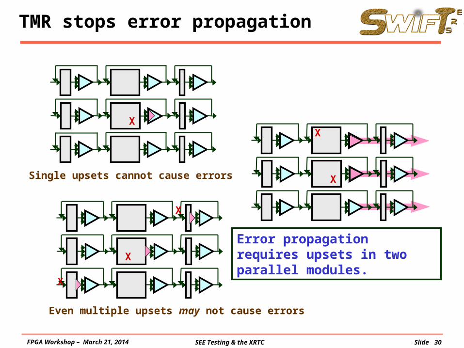
TMR stops error propagation
Single upsets cannot cause errors
Error propagation requires upsets in two parallel modules.
X
X
X
X
X
X
Even multiple upsets may not cause errors
FPGA Workshop – March 21, 2014
SEE Testing & the XRTC Slide 31
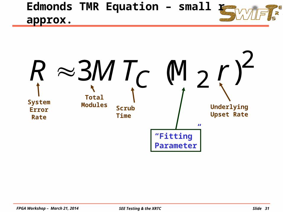
Edmonds TMR Equation – small r approx.
).-(small )(3 22 rrTMR C M
Scrub Time
System Error Rate
UnderlyingUpset Rate
Total Module
s
“Fitting” Parameter
FPGA Workshop – March 21, 2014

SEE Testing & the XRTC Slide 32
Edmonds TMR Equation – small r approx.
).-(small )(3 22 rrTMR C M
Scrub Time
System Error Rate
UnderlyingUpset Rate
Total Module
s
.1
,1
,1
4/1
1
44
3/1
1
33
2/1
1
22
M
ii
M
ii
M
ii N
MN
MN
MMMM
Parameter is really the second moment of the distribution of
N’s. This is a “cousin” of the
standard deviation.
FPGA Workshop – March 21, 2014

SEE Testing & the XRTC Slide 33
Example Application - BRAM Scrubber
Given parameters: T=2 ms, M=48000 Fit parameter: M2=M3=M4= 250
BRSCRUB
r (bit errors/bit-second)1e-6 1e-5 1e-4 1e-3 1e-2 1e-1
R (
syst
em e
rror
s/se
cond
)
0.001
0.01
0.1
1
10
100
1000datageneral approximation small-r form extrapolated
FPGA Workshop – March 21, 2014

SEE Testing & the XRTC Slide 34
In Review …
• New Edmonds Equation for TMR is– General (for TMR-ed systems)– Powerful
• Works over many orders-of-magnitude
– Based on moments which are• Statistically meaningful
• Of rapidly diminishing importance so only one (or two) adjustable parameters are enough
• Calculable, in theory anyway; in practice, probably not.
– Useful• In predicting system error rates in space
• In designing appropriate in-beam testing– Consortium uses “three-flux” test for all mitigated experiments using
spacing of an order of magnitude or more
FPGA Workshop – March 21, 2014

SEE Testing & the XRTC Slide 35
The End
Thank you!
Any questions?
FPGA Workshop – March 21, 2014