master thesis electrical engineering december 2012833482/fulltext01.pdfmaster thesis electrical...
TRANSCRIPT

Master ThesisElectrical EngineeringDecember 2012
Analysis of Radio Access Network Buffer FillingBased on Real Network Data
Logabharathi Aruchamy
School of ComputingBlekinge Institute of Technology37179 KarlskronaSweden

This thesis is submitted to the School of Computing at Blekinge Instituteof Technology in partial fulfillment of the requirements for the degree ofMaster of Science in Electrical Engineering. The thesis is equivalent to 20weeks of full time studies.
Contact Information
Author:Logabharathi AruchamyE-mail: [email protected]
External Advisor(s)
Tomas Lundborg,Systems Manager,Ericsson AB,Development Unit Radio-System andTechnology,Torshamnsgatan 33,164 80 Stockholm, Sweden.
Mathias Sintorn,Senior Specialist R&D,Ericsson AB,Development Unit Radio-System andTechnology,Torshamnsgatan 33,164 80 Stockholm, Sweden.
University advisor:
Prof. Markus Fiedler,School of Computing (COM)
School of ComputingBlekinge Institute of Technology371 79 KARLSKRONA SWEDEN
Internet: www.bth.se/comPhone: +46 455 385000SWEDEN

Abstract
The 3G and 4G networks have drastically improved availability andquality in data transmission for bandwidth hungry services such as videostreaming and location-based services. As 3G networks are very widelydeployed, there exists increased capacity requirement and transportchannel allocation to simultaneous users under a particular cell. Due tothis reason, adequate resources are not available, which in turn degradesboth service quality and user experienced quality. This research aims atunderstanding the characteristics of buffer filling during dedicated channel(DCH) transmission under fixed bit-rate assumptions on a per-user leveltaking different services into consideration. Furthermore, the resourceutilisation in terms of empty buffer durations and user throughputachieved during dedicated channel transmission are also analysed fordifferent data services existing in the mobile networks. The traces arecollected from a real network and characteristics of the traffic are analysedprior to understanding its buffer filling in Radio Network Controller(RNC) during downlink data transmission. Furthermore, the buffer ismodelled with some series of assumptions on channel bit-rates andsimulations are performed taking single user scenario into consideration,for different services with the help of obtained traces as input to the buffer.This research is helpful in understanding the RNC buffer filling fordifferent services, in turn yielding possible understanding on the existingtransport channel switching scenario. With the help of analysing the bufferfilling for different services and transport channel utilisation, we learn thatmost of the data services show low DCH utilisation of approximatelyaround 20% and also found to have 80% of the total DCH session durationwith empty buffer, causing sub-optimal radio resource utilisation.
Keywords: Traffic Characteristics, Radio Network Controller (RNC),Dedicated Channel (DCH) and Channel Switching.
i

Acknowledgement
It would not have been possible to complete my thesis work withoutthe help and support of the kind people around me, to only some of whomit is possible to give particular mention here.
Foremost, I would like to express my deepest sense of Gratitude toJessica Ostergaard, Manager, Radio Networks - Systems and Concepts,Ericsson AB, for giving me such an wonderful opportunity to perform thisthesis work at Ericsson AB.
At this moment of accomplishment, I gratefully acknowledge TomasLundborg, Systems Manager for his continuous advice and encouragementthroughout the course of this thesis. I thank him for his systematicguidance and great effort he put into training me in the scientific field. Mysincere thanks also goes to Mathias Sintorn, Senior R&D Specialist, for hisinsightful comments and absolute support to the thesis.
I am most grateful to Prof. Markus Fiedler for his technical supportand encouragement whenever I was in need.
I would also like to thank my friends in Ronneby, Karlskrona andStockholm for all the fun we have had during my stay in Sweden.
Last, but by no means least, I would like to express the profoundgratitude from my deep heart to my parents: Aruchamy and Lakshmi andmy brother: Gopienathan for their love and continuous support - bothspiritually and materially.
ii

Contents
Abstract i
Acknowledgement ii
Contents iii
List of Figures vi
List of Tables viii
List of Acronyms ix
1 Introduction 11.1 Scope . . . . . . . . . . . . . . . . . . . . . . . . . . . . . . . 11.2 Study Prerequisites . . . . . . . . . . . . . . . . . . . . . . . . 21.3 Working Process . . . . . . . . . . . . . . . . . . . . . . . . . 21.4 Contribution . . . . . . . . . . . . . . . . . . . . . . . . . . . 31.5 Reader Guidance . . . . . . . . . . . . . . . . . . . . . . . . . 3
2 Background 52.1 3G Network Architecture . . . . . . . . . . . . . . . . . . . . 5
2.1.1 WCDMA UMTS Components [27] . . . . . . . . . . . 52.1.2 Radio Network Controller (RNC) . . . . . . . . . . . . 82.1.3 Radio Resource Management (RRM) . . . . . . . . . . 9
2.2 Data Trace Analysis . . . . . . . . . . . . . . . . . . . . . . . 102.2.1 Trace Generation . . . . . . . . . . . . . . . . . . . . . 102.2.2 Trace Analysis . . . . . . . . . . . . . . . . . . . . . . 12
2.3 Related Work . . . . . . . . . . . . . . . . . . . . . . . . . . . 16
iii

3 Research Methodology 193.1 Aim and Objectives . . . . . . . . . . . . . . . . . . . . . . . 193.2 Research Questions . . . . . . . . . . . . . . . . . . . . . . . . 193.3 Research Methodology . . . . . . . . . . . . . . . . . . . . . . 20
4 Traffic Data Analysis 224.1 Service Distribution . . . . . . . . . . . . . . . . . . . . . . . 224.2 IP Packet Characteristics . . . . . . . . . . . . . . . . . . . . 23
4.2.1 Packet Sizes [SP] . . . . . . . . . . . . . . . . . . . . . 234.2.2 Inter-arrival Times [IP] . . . . . . . . . . . . . . . . . 25
4.3 Burst Characteristics . . . . . . . . . . . . . . . . . . . . . . . 264.3.1 Burst Inter-arrival Times [I B] . . . . . . . . . . . . . . 274.3.2 Burst Durations [DB] . . . . . . . . . . . . . . . . . . 294.3.3 Burst Sizes [SB] . . . . . . . . . . . . . . . . . . . . . 31
4.4 Session Characteristics . . . . . . . . . . . . . . . . . . . . . . 344.4.1 Duration of Sessions [DS] . . . . . . . . . . . . . . . . 344.4.2 Data Volume Transmitted per Session [SS
A] . . . . . . 354.4.3 Clean Service Traffic Percentage [C S] . . . . . . . . . 37
4.5 Summary . . . . . . . . . . . . . . . . . . . . . . . . . . . . . 38
5 RNC Buffer Modelling 405.1 Trace-Based Simulation Buffer Model . . . . . . . . . . . . . 405.2 Design Assumptions . . . . . . . . . . . . . . . . . . . . . . . 435.3 Transport Channels and State Transitions . . . . . . . . . . . 445.4 Effects of Buffering Delays and QoS . . . . . . . . . . . . . . 465.5 Attained Buffer Levels . . . . . . . . . . . . . . . . . . . . . . 485.6 Summary . . . . . . . . . . . . . . . . . . . . . . . . . . . . . 50
6 Results and Discussion 526.1 Idle buffer Characteristics during Dedicated Channel
Transmission . . . . . . . . . . . . . . . . . . . . . . . . . . . 526.1.1 Empty Buffer Duration [De] . . . . . . . . . . . . . . . 536.1.2 Percentage of Emptiness in Buffer per DCH Session [Pe] 55
6.2 Radio Resource Utilisation in terms of Dedicated ChannelPerformance . . . . . . . . . . . . . . . . . . . . . . . . . . . . 576.2.1 Achieved User Throughput on DCH [Ta] . . . . . . . . 586.2.2 Dedicated Channel Utilisation [UDCH] . . . . . . . . . 60
6.3 Discussion of the Results . . . . . . . . . . . . . . . . . . . . . 626.4 Validity of the Results . . . . . . . . . . . . . . . . . . . . . . 63
7 Conclusion and Future Work 657.1 Conclusion . . . . . . . . . . . . . . . . . . . . . . . . . . . . 657.2 Future Work . . . . . . . . . . . . . . . . . . . . . . . . . . . 66
iv

Bibliography 68
Appendix 71
A Sub-types of Services 72
v

List of Figures
1.1 Working Process . . . . . . . . . . . . . . . . . . . . . . . . . 3
2.1 Simplified 3GPP UMTS network reference model . . . . . . . 62.2 UTRAN Components and Interfaces . . . . . . . . . . . . . . 72.3 Overview of RNC in UTRAN connecting CN and UE . . . . 82.4 Modes of RRC and CELL States of UE . . . . . . . . . . . . 92.5 Differentiation criteria for services from the traffic logs [1] . . 122.6 Essential terms and their definitions with respect to traffic [11] 15
3.1 Step-by-step flow of the research work . . . . . . . . . . . . . 21
4.1 Service Distribution . . . . . . . . . . . . . . . . . . . . . . . 234.2 Packet sizes for different services . . . . . . . . . . . . . . . . 244.3 Inter-arrival times between packets for different services . . . 264.4 Inter-arrival time between bursts for different services . . . . 284.5 Mean Inter-Arrival Time between Bursts . . . . . . . . . . . . 294.6 Duration of Bursts for different services . . . . . . . . . . . . 304.7 Average Burst Durations . . . . . . . . . . . . . . . . . . . . . 314.8 Burst sizes for different services . . . . . . . . . . . . . . . . . 324.9 Mean burst sizes for different services . . . . . . . . . . . . . 334.10 Durations of Sessions for different services . . . . . . . . . . . 354.11 Data Volume per Session for different services . . . . . . . . . 364.12 Mean Clean Service Traffic Percentage for different services . 38
5.1 Calculation of different parameters of the buffer model . . . . 425.2 Flowchart of RNC buffer model in relation with queueing . . 435.3 Switching between transport channels and UE State Transitions 455.4 Average Buffering Delays for different services . . . . . . . . . 475.5 Buffer filling levels for different services . . . . . . . . . . . . 495.6 Average buffer levels for different services . . . . . . . . . . . 50
6.1 Idle Durations of Buffer during DCH transmission . . . . . . 546.2 Average Idle Durations of Buffer during DCH transmission . 556.3 Empty Buffer Percentage during DCH sessions . . . . . . . . 566.4 Average Empty Buffer Percentage during DCH sessions . . . 57
vi
6.5 Achieved Throughput on DCH transmission . . . . . . . . . . 596.6 Average Achieved Throughput on DCH transmission . . . . . 606.7 Utilisation of Dedicated Channel for different services . . . . 616.8 Average Utilisation of Dedicated Channel for different services 62
vii

List of Tables
2.1 UE states and Transport Channels with correspondingachievable bit-rates [27] . . . . . . . . . . . . . . . . . . . . . 10
2.2 Sample tags captured from the traffic capturing tool . . . . . 14
5.1 QoS End-to-End Packet Delay Range for Different Services [13] 46
viii

List of AcronymsCN Core Network
CS Circuit Switched
DCH Dedicated Channel
DPCCH Dedicated Physical Control Channel
DPDCH Dedicated Physical Data Channel
DRX Discontinuous Reception
ETSI European Telecommunications Standard Institute
FACH Forward Access Channel
FIFO First In First Out
FTP File Transfer Protocol
GBR Guaranteed Bit Rate
GSM Global System for Mobile Communication
IMEI International Mobile Equipment Identity
IMSI International Mobile Subscriber Identity
ISDN Integrated Services Digital Network
LTE Long Term Evolution
MS Mobile Station
MSC Mobile Station Controller
NBAP Node-B Application Part
PS Packet Switched
PSTN Public Switched Telephone Network
QoS Quality of Service
QoE Quality of Experience
RAB Radio Access Bearer
RACH Random Access Channel
ix

RAN Radio Access Network
RLC Radio Link Control
RNC Radio Network Controller
RNSAP Radio Network Application Subsystem Part
RRC Radio Resource Control
RRM Radio Resource Management
SF Spreading Factor
SGSN Serving General Packet Radio Service Support Node
SLA Service Level Agreement
UE User Equipment
UMTS Universal Mobile Telecommunications System
URA UTRAN Registration Area
UTRAN UMTS Terrestrial Radio Access Network
VLR Visitors Location Register
WCDMA Wideband Code Division Multiple Access
x
Chapter 1
Introduction
Due to ever-increasing users and subsequent network capacityrequirements, resource optimization techniques to ensure optimal use ofradio resources in the network to achieve good service quality are underresearch.
Moreover, the performance of different services in the radio networkscenario in terms of network parameters such as user throughput, emptyRNC buffer periods and transport channel utilisation are very importantto understand the impact of poor resource usage on the system capacity.In addition, unwanted resource occupied by one user in a particular cellleads to poor experienced quality for another user in the same cell due tomore delay, latency and jitter in the transmission, caused by inadequatechannel capacity.
With the help of some suggestions from [10], related to fundamentallimitations of the current state machine design with respect to statetransitions and down-switch timer in terms of system overhead andperformance, there is a need to emphasize further on performancevariations observed during the existence of traffic for different data servicesin RAN. In this research, considering different services and their trafficfrom real network traces, the buffer filling is analysed and performancevariations in terms of channel utilisation is studied.
1.1 Scope
The performance study conducted in this research will evaluate howdifferent services fill the RNC buffer in live networks with fixed channelbit-rate considerations. This will be determined by understanding thecharacteristics of input traffic data and different output parameters of the
1
modelled buffer in terms of Cumulative Distribution Function (CDF),mean values and confidence intervals (CI).
The report will demonstrate the obtained traffic characteristics, RNCbuffer model and finally illustrate the results obtained from the buffermodel with default channel bit-rate considerations, after supplying theepoch timestamps and corresponding packet sizes from real network tracesas input. The discussions will be made regarding the bursty behaviour ofthe traffic models, empty buffer behaviour and dedicated channelutilisation.
1.2 Study Prerequisites
For the work conducted in this research, the prerequisites needed were:
• Knowledge of the networking protocols used in today’s 3G and 4Gmobile networks.
• Understanding of queuing theory and its application on teletrafficengineering and packet data networks.
• Knowledge of statistical modelling and empirical data analysis withunderstanding related to cumulative distribution, mean, standarddeviation and confidence interval.
An initial study was conducted for four weeks during which a selectednumber of books and articles were read, which provided knowledge onmobile communication in general, the basics of 3G and 4G networks, thetransmission protocols, Radio Access Network (RAN) architecture andqueuing theory in general.
1.3 Working Process
The RNC buffer model makes a series of assumptions andapproximations on the behaviour of the mobile networks it is designed toemulate. According to these assumptions and the input traffic data, themodel estimates the empty buffer time and DCH utilisation for the usersusing different services. For achieving the outcomes, the working processas shown in Figure 1.1 is involved.
2

Service
Name
User 1
User 2
User N
RNC Buffer
Model
Estimation of Buffer and
DCH Parameters
Trace Files
Collected
through Traffic
Capturing tool
Parsed Trace
File
according to
service tags
Traffic Data
Analysis
Figure 1.1: Working Process
Further explanations on the research methodology and process flow willbe explained in detail in Chapter 3.
1.4 Contribution
The major contributions of this thesis work are as follows:
• A methodology for evaluation of RNC buffer filling with real networktraces, taking different services into consideration.
• Analysis of traffic data in terms of packet sizes and inter-arrival timesfor different services and its performance variations during dedicatedchannel transmissions.
• Presentation of results in terms of empty buffer time, user throughputand transport channel utilisation obtained from modelled buffer tounderstand radio resource utilisation with respect to RNC buffer anddedicated channel for different services.
1.5 Reader Guidance
The remainder of the report is organised as follows. The backgroundinformation, key concepts covering 3G network architecture, data traceanalysis and related work are explained in Chapter 2. Chapter 3 describesthe aim and objectives, followed by the research questions and researchmethodology.
In Chapter 4, the traffic data analysis from the obtained real networktraces for different services is covered. The RNC buffer modelling withdesign assumptions and validations are explained in Chapter 5 and
3

subsequent results are discussed in Chapter 6. Finally key conclusions withpotential future directions of the research are explained in Chapter 7.
4

Chapter 2
Background
2.1 3G Network Architecture
The Universal Mobile Telecommunication Systems (UMTS) is designedto have flexible delivery of any type of service with no requirement ofnetwork optimisation for each service [27]. UMTS is evolving to cope withever-increasing need of wireless data services such as multi-mediamessaging, video streaming, location based services, mobile commerce andon-line gaming.
This section is organised as follows, Section 2.1.1 explains essentialcomponents of WCDMA UMTS network briefly, followed by Section 2.1.2about Radio Network Controller (RNC) and its modes of operation interms of buffer behaviour and Section 2.1.3 covers Radio ResourceManagement (RRM) present in UTRAN for resource control mechanisms.
2.1.1 WCDMA UMTS Components [27]
According to the 3GPP reference network model, UMTS consists of fourmajor network components as follows:
• User Equipment (UE)
• Radio Access Network (RAN)
• Core Network (CN)
• External Network (e.g., IP networks, PSTN/ISDN)
The UE is the end-user electronic device such as Android/iPhone, iPad orPC dongle connected to the network through Mobile Station (MS). Inaddition, the data bandwidth of the UE is significantly limited by thebattery capacity of UE due to MS power consumption during wireless datatransmission [18].
5

In 3GPP and ETSI, the RAN is termed as UTRAN (UMTS TerrestrialRAN) and this network part is of our research interest. Severalcomponents making up this network will be explained to understand howbits are transmitted over the radio interface.
Circuit-
Switched
Domain
RNC
External Network Radio Access
Network (RAN)
User
Equipment
(UE)
Node B
Core
Network
(CN)
Packet
Switched
Domain
PSTN/ISDN
IP Network
WCDMA
Figure 2.1: Simplified 3GPP UMTS network reference model
The core network is similar to the GSM network havingpacket-switched or circuit-switched domains according to externalnetworks such as PSTN/ISDN or IP networks respectively. In addition,the CN is responsible for switching/routing calls and data connections toexternal networks, whereas RAN handles all radio-related functionality.
As far as RAN is considered, it is essential to understand thefunctionalities of the following components,
• Radio Base Station (Node B)
• Radio Network Controller (RNC)
• Interfaces
Node BThis provides air interface L1 processing such as channel coding and
interleaving, rate adaptation, spreading and so on. Some of the radioresource management functions like inner loop power control are alsocarried out by Node B.
Logical functionalities of RNCLoad and congestion control of its own cells and execution of admission
control and code control for new radio links to be established are handled
6

by the Controlling RNC (CRNC). Whereas, Serving RNCs (SRNC)perform L2 processing of data to/from the radio interface, mapping ofRadio Access Bearer (RAB) parameters into air interface transportchannel parameters, hand-over decisions and outer-loop power control.
In the same way, the Drift RNCs (DRNC) control cells used by themobile, macro diversity combining and splitting. A single RNC normallycontains all the CRNC, SRNC and DRNC functionalities.
UTRAN Interfaces
Figure 2.2: UTRAN Components and Interfaces
1. UTRAN-CN (Iu)As can be seen from Figure 2.2, Iu has two different instances, whichdiffer according to the type of external network. If the externalnetwork is a circuit-switched (CS) network consisting of MobileSwitching Center (MSC)/Visitors Location Register (VLR), theinterface is termed Iu-CS. On the other hand, Iu-PS is used in case ofa packet-switched (PS) network with Serving General Packet RadioServices Support Node (SGSN). Another interface, Iu Broadcast(Iu-BC), is used for the Broadcast domain of CN, which is not shownin Figure 2.2.
2. RNC-RNC (Iur)This interface is primarily to enable inter-RNC soft handover, but ithas some additional functionalities such as
(a) Inter-RNC mobility;
7

(b) Dedicated channel traffic handover;
(c) Common channel traffic handover;
(d) Global resource management.
The signalling protocol is Radio Network Subsystem Application Part(RNSAP) and it is possible to implement any one of the four Iurmodules between two RNCs, according to operators’ requirements.
3. RNC-Node B (Iub)In case of the Iub interface, traffic termination is one of the mainfunctions and the signalling interface is Node B Application Part(NBAP), which is divided into common NBAP (C-NBAP) forsignalling procedures across common signalling links and dedicatedNBAP (D-NBAP) used in dedicated signalling links.
4. Node B-UE (Uu)Finally, the Uu interface is between the RAN and UE, which with thehelp of MS, transmits data over the radio interface.
2.1.2 Radio Network Controller (RNC)
The RNC plays an important role in maintaining the proper flow ofdata according to available bit rates over the radio link. Moreover, thereare several protocols, which make this process easier to control, as there isa large number of users sharing a particular RNC. It owns and controls theresources in the radio network in its domain and also manages theconnections to UE [27].
UMTS Core
Network
Processor Buffer
RNCNode B
UE
External Network
Figure 2.3: Overview of RNC in UTRAN connecting CN and UE
As shown in the Figure 2.3, the RNC processes the packets receivedfrom CN by queuing the packets and transmitting with a defined bit-rate,
8

which is dependent on the radio link allocation for the user based on theservice level agreement (SLA) agreed between the service provider and theusers. However, the attained bit-rates vary over time due to varyingnetwork conditions, transport channel availability and number of userswithin a particular cell.
2.1.3 Radio Resource Management (RRM)
RRC messages in terms of handovers, cell updates and measurementsbetween UE and UTRAN are performed by the RRM functionalities presentin the RAN. There are two basic modes of operation: idle and connectedmode.
Idle Mode
CELL_DCH
CELL_FACH
CELL_PCH URA_PCH
Connected Mode
Figure 2.4: Modes of RRC and CELL States of UE
IdleDuring idle mode, the UE can receive system information and
broadcasting messages through RRC signaling, but UTRAN has noconnection with UE at this point and does not have any information aboutthe idle mode UEs. However, the connection can be created throughpaging (network initiated) or random access (UE initiated).
ConnectedOn the other hand, during connected mode, there can be four possible
states such as CELL DCH, CELL FACH, CELL PCH and URA PCH asshown in Figure 2.4. In these states, CELL represents the current cell,URA represents the UTRAN Registration Area, under which the RNC canlocate the UE. Furthermore, the UE can transmit or receive data throughany of the following transport channels as shown in Table 2.1.
During the CELL DCH state, DCH is allocated for the user, which canbe mapped to physical channels such as Dedicated Physical Data Channel(DPDCH) or Dedicated Physical Control Channel (DPCCH). This hashigher transmission rates to provision high bandwidth services.
9

Conversely, during low bit-rates, UE is forced to CELL FACH state.Thus data transmission is achieved through FACH having low bit rates asthe channel is shared.
In the CELL PCH state, the user can be contacted through PCH andthe user is known on the cell level in this state. This same scenario isapplicable in URA PCH, except that the user can be known on URA leveland paging is over the entire URA.
The channel-switching functions are carried out by Radio ResourceManagement (RRM) function through Radio Resource Control (RRC)protocol messages. In other words, the UE will be assigned appropriatetransport channels, and the data rate is controlled, through RRM.
Table 2.1: UE states and Transport Channels with corresponding achievablebit-rates [27]
UE State TransportChannel
Practical Bit-Rates
CELL DCH DedicatedChannel(DCH)
High, up to 2 Mbps
CELL FACH ForwardAccessChannel(FACH)
Low, up to 64 kbps
CELL PCH/URA PCH PagingChannel(PCH)
Only Signalling/Paging
2.2 Data Trace Analysis
This part is organised as follows, Section 2.2.1 explains the way inwhich the traces i.e. traffic data are collected and their properties wedetermined and Section 2.2.2 covers the important terms used in thereport to understand the analysis and how the traffic data analysis on peruser basis is performed for different services.
2.2.1 Trace Generation
To address the characteristics of the buffer filling for different servicesin the RNC of UTRAN, traces are collected from an operating 3G networkin a major American city. In addition, the data is collected at the interfacebetween CN and RAN, i.e. Iu-PS using a traffic capturing tool, which is an
10

Ericsson tool set to measure and analyse IP traffic.
Furthermore, it processes and classifies traffic online and instead of fulltraces, only stores traffic statistics at various levels of detail. It should alsobe noted that the delay or jitter between CN and RAN (which is in theorder of a few ms) is not expected to have relevant impact on the study.
This tool classifies the user plane traffic using a set of rules andassociated decision logic defined in an XML file. So, during evaluation ofthe rules, payload of incoming packets is matched against each rule. Inaddition, the set of rules are freely modifiable and extensible and it alsoprovides a way to filter or process the complete measurement data alongpre-defined aspects. For this, each user data flow may have zero or moretags attached to it, as defined by the classification rules.
The traces are collected for every single minute interval for 2 dayscontinuously, which resulted in 2880 trace files each having file size ofaround 5000 kB containing traces of the packet data traffic and it shouldbe noted that there is no voice data collected, and that packet trafficinformation is collected from 3G network only.
In addition, each packet is identified using timestamps, TCP/UDPsession, source IP address and port number, destination IP address andport number, uplink/downlink, encoded International Mobile SubscriberIdentity (IMSI), International Mobile Equipment Identity (IMEI) andservice tags.
It should be noted that the link bit-rates exhibited in the radio networkare not known. Furthermore, the information on the network policycontrol framework of the network was not possible to obtain because ofsensitivity of the information from the mobile operator’s point of view.
So assumptions on channel bit-rates are made and buffer fillings underthis scenario for different services are studied.
11

2.2.2 Trace Analysis
QoS Classes
Services
Service
Sub-Types
Gaming Web-browsing Email ...
Web-browsing-HTTP-Google Social-Networking-SSL-Facebook
...
InteractiveStreamingConversational Background
Guaranteed Bit-RateNon-Guaranteed Bit-Rate
Figure 2.5: Differentiation criteria for services from the traffic logs [1]
1. QoS ClassesThe QoS class is the differentiation of services in terms of whether ithas guaranteed bit-rate or not in the radio network. Each service hasits own traffic parameters according to QoS differentiation in termsof priority, packet delay and packet error loss rate. In Section 5.4,the QoS packet delay parameter for each service will be explained indetail.
From the bit-rate considerations observed in the real networkscenario, the Guaranteed Bit-Rate (GBR) bearer carries traffic thatrequires a minimum bit-rate guarantee from the network, while thenon-Guaranteed Bit Rate (non-GBR) bearer carries variable bit-ratetraffic and is offered as best-effort service by the network [11].
As shown in the Figure 2.6, the conversational and streamingservices, which are real-time or GBR services need low packet delayand loss ratio. On the other hand, non-GBR services such asbackground services are considered to be delivered with best effort.
Moreover, as the research is related only to the data services in thewireless networks, the conversational services such as voice or videocalling are not considered.
2. ServicesThe traffic data collected has different services, but to reduce the
12

complexities, all the major services are only taken out from the tracefiles. The service here is termed as functionality in the trafficcapturing tool, which will be an essential parameter to differentiatethe packet when it is collected.
According to 3GPP 23.107, the services are differentiated accordingto their QoS in the following way to understand their characteristicsrelated to this research separately. However, the extent of QoS basedprioritization in the input traces is not known. Moreover, this is notrelevant for the study, since the analysis is considered with a singleuser at a time.
(a) GBR Streaming
• video-playback
• audio-playback
• media-playback
(b) Non-GBR Interactive
• instant-messaging
• gaming
• web-browsing
• social-networking
• maps
(c) Non-GBR Background
• file-download
• advertisement
• software-update
• file-sharing
It should be noted that media-playback is the real-time streaming withprotocols such as RTP, RTSP, whereas video and audio-playback arebuffered streaming with HTTP protocol.
3. Service Sub-Types
Furthermore, the tags that are attached to flows are grouped intofacets, representing different aspects of the traffic. Facets include
• FunctionalityThe functionality or service tells the activity type for which theflow is used and this comprises of social-networking,web-browsing, instant-messaging, gaming, maps,software-update, file-download, email, video-playback,audio-playback, media-playback and advertisement.
13

• ProtocolThis tells the protocol carrying this flow such as HTTP, FTP,XMPP, SIP, SSH, RTSP and RTP.
• Service-providerThere are several service providers, who provide services ondifferent functionalities such as Google providing email,web-browsing and maps services. So this tells whichservice-provider is behind the flow, if there existsservice-provider information in the packet data.
• Client-applicationSimilar to service providers, the same service can be accessedthrough different applications such as web-browsing throughMozilla Firefox, Chrome or Internet Explorer.
• EncryptionMost of the secure services need encryption, so as to ensure thedata security in terms of confidentiality, integrity andauthenticity by enabling SSL for the data transmission. Thedata security and protection in the radio network is achievedthrough Packet Data Convergence Protocol (PDCP), whichprovides header compression algorithms for IP packets. Inaddition, these algorithms can be negotiated during RRC RadioBearer (RB) establishment or reconfiguration procedures [27].
• EncapsulationAdditionally, encapsulation is also found in some services tosecure the transmission further to protect the data fromintruders.
For example a flow can be characterised like sample tags given in theTable 2.2.
Table 2.2: Sample tags captured from the traffic capturing toolprotocol functionality service-
providerclient-application
encryption
HTTP social-networking
Facebook Mozilla-Firefox
SSL
HTTP video-playback
Apple iPhone-Media-Player
-
RTSP media-playback
- - -
14

IP PACKETS
BURSTS
SESSIONS
time (s)
time (s)
time (s)
Burst
Sizes
(bytes)
> 200 ms
S1
B1
S2
> 300 sSession
Sizes
(bytes)
Burst
Duration
B2
Session
Duration
USERS
time (s)
U1 U2
B3
Figure 2.6: Essential terms and their definitions with respect to traffic [11]
4. IP PacketsThe major information of IP packets from the traces such as epochtimestamps and IP packet sizes will be analysed for anyregularities/irregularities in the traffic flow for different services.
5. BurstsIt is important to understand the term bursts, which is assumed tobe a set of one or more IP packets arriving with inter-arrival timeless than 200 milliseconds as shown in Figure 2.6. Even if it is asingle packet with no packets accompanying it with inter-arrival timeless than 200 ms, then that particular packet is also considered as aburst.
It should be noted that, the inter-arrival time of packets within aburst can be assumed with different values other than 200 ms such as2 s, 5 s or 10 s and so on for different services depending on theassumptions on user behaviour, but it is assumed to have a fixedvalue in this study i.e. 200 ms for all the services to reducecomplexity in comparison and analysis. In addition, this value isassumed only after prior understanding of the packet inter-arrivals
15

and related analysis on the traffic data. So, if the packet inter-arrivaltime is more than 200 ms, then it will be considered as the end of thecurrent burst or start of the next burst.
It is interesting to know about the characteristics of the bursts interms of inter-arrival times, duration and size of bursts for differentservices in the radio network scenario. In addition, numerousresearch work state the principle of bursty behaviour in packetarrivals for most TCP services, rather than regular inter-arrivals ofpackets.
6. SessionsFor a single user, there may be continuous flow of packets for acertain time period or intermittent gaps between the packet flows,when a single service is considered. Thus, as shown in Figure 2.6, asession is termed as the traffic during downlink data transmissionwith no inactivity for about 300 seconds. If there is such aninactivity, the session is assumed to terminate and new session forthe same user starts again with arrival of packets belonging to thesame service considered.
7. UsersIf a particular service is considered, the whole trace file is checked withthe help of tags, for the users who use this service. This informationis used for further investigating into the flow of packets towards theuser for different services.
After the differentiation of services with the aforementioned criteria, theresearch is carried out on analysing several parameters both from the trafficand buffer model implemented. Finally, the analysis of essential parametersto understand the radio resource utilisation is also made.
2.3 Related Work
The ever-increasing need for high-bandwidth applications accessiblethrough 3G and LTE networks widens the research opportunities inanalysing existing network scenario and identifying possible qualityenhancements and resource optimization procedures in the radio networks.In addition, there are various work related to performance measurementswith the help of emulation of a real network and analysis of severalparameters involving quality improvements in the wireless networks.
16

RNC Buffer Related Work
In [19], analysis of TCP performance with respect to RLC buffer size isanalysed, with the help of simulations carried out resembling the real radionetworks and there are reflections of TCP congestion control mechanismssuch as slow start (exponential growth) and congestion avoidance (lineargrowth). The ETSI discrete event simulation model is proposed to studythe Discontinuous Reception (DRX) mechanism exercised between thenetwork and MS to study the inactivity timer threshold and DRX cycle[14]. In addition, the expected waiting times, queue length and powersaving factor are also analysed in [14].
A research work related to usability of instant messaging service over a3G WCDMA network gives the technical performance analysis andusability evaluations of the radio network controller under differentnetwork set-ups [25]. An analysis related to link throughput according tochanges in the buffer size by varying TCP flavour (Tahoe, Reno, NewRenoor SACK), FTP file size, RLC buffer size and DCH data rates is conductedin [23]. The performance of TCP over dedicated channels with different bitrates and different transmission time intervals (TTI) is examined tounderstand end-to-end packet delay, delay in the radio access network andthroughput in the wireless link [17].
RRM Related Work
The findings in [10] suggest the fundamental limitation of the currentstate machine design with respect to transitions and timer values in UMTSnetwork. The up-switching threshold (bytes) and down-switching timer(seconds) for transport channel switching are considered to be staticleading to consideration of all traffic with same characteristics leading tothe difficulty in balancing the trade-off between network essentials in termsof network management, system overhead and performance.
Some of the accessibility issues such as termination failures andfrequent user registrations are studied to understand the performance ofthe network according to user types and device types in [9].
In addition, resource utilization in terms of channel switching is animportant consideration, under which there are various algorithmsproposed to meet the specifications of RNC and evaluations are made withthe help of simulations. Furthermore, several impacts of parameter settingson performance with respect to packet loss probability and utilisation ofdedicated channels are analysed in [16]. Moreover, the behaviour ofNon-Real-Time sessions and channel switching are evaluated with the help
17

of blocking rate, mean packet delay and cell throughput to decrease thenumber of blocked calls keeping other metrics at a satisfactory level [24].
Even though there are numerous works in the radio resource andperformance analysis, this research aims at studying in detail the RNCbuffer filling with fixed channel bit-rate conditions, taking the most widelyused data services existing in wireless 3G and LTE networks intoconsideration.
18

Chapter 3
Research Methodology
This chapter is organised as follows: Section 3.1 explains the aim andobjectives, Section 3.2 gives the guiding questions to be addressed andmotivation behind the research and Section 3.3 describes the researchmethodology handled in order to fulfil the goals of the thesis work.
3.1 Aim and Objectives
The goal of this thesis work is to investigate how traffic from real,operating networks impacts the buffer filling in the radio network nodes.The objectives to achieve this goal are to
• analyse packet traces from real networks;
• fit a parameterized model of IP packet inter-arrival times and IPpacket sizes to the existing packet traces, taking into accountdifferent services;
• implement and analyse different parameters of the RNC buffer model;
• evaluate buffer filling for users using different services in the radionetwork, in terms of resulting parameters of the model;
• with the resulting level of buffer filling, analyse radio resourceutilization and radio network performance in terms of RNC bufferand DCH parameters for different services.
3.2 Research Questions
The leading questions that should be addressed in this research work are
• RQ 1: What are the variations in terms of inter-arrivals, durationsand size of bursts of IP packets for different services?
19

• RQ 2: How long does the RNC buffer show empty buffer levels duringDCH transmission for different services?
• RQ 3: How do different services perform on dedicated channel datatransmission in terms of user throughput and channel utilisation?
The first question is mainly to find out the distribution of the trafficmodels supplied to the buffer as input to understand the characteristics ofthe data traffic obtained.
The second question is framed to address how different services incurempty durations in the RNC buffer due to intermediate inactivity duringdedicated channel transmission according to the channel bit-rateconditions assumed. In addition, this is essential to gather informationabout the performance of different services in the radio network in terms ofbuffer utilisation.
From the third question, the analysis will reflect the radio resourceutilisation with respect to dedicated channel for different services.
3.3 Research Methodology
The research work comes under the category of empirical data analysisand it deals with traffic data analysis of obtained traces with respect todifferent services and further investigation related to the radio network bufferfilling for different services. The following describes the steps carried out toobtain the necessary outcomes of this research as shown in Figure 3.1.
1. The data traffic is analysed to get the knowledge of obtainableparameters from the trace files.
2. The traces are classified according to different services so as to beanalysed further in terms of important parameters of the traffic andthis is mentioned in Section 2.2.
3. From the traces, the packet sizes and inter-arrival times are examinedfor different services and bursts of the data traffic is also analysed, soas to understand the regularities or irregularities of bursts in trafficfor different services.
4. The RNC buffer is modelled with a series of assumptions andapproximations to understand how buffer performance is affected bydifferent services in a real RNC.
5. The obtained traffic separated as sessions for different services aresupplied as input to the buffer to evaluate the buffer filling.
20
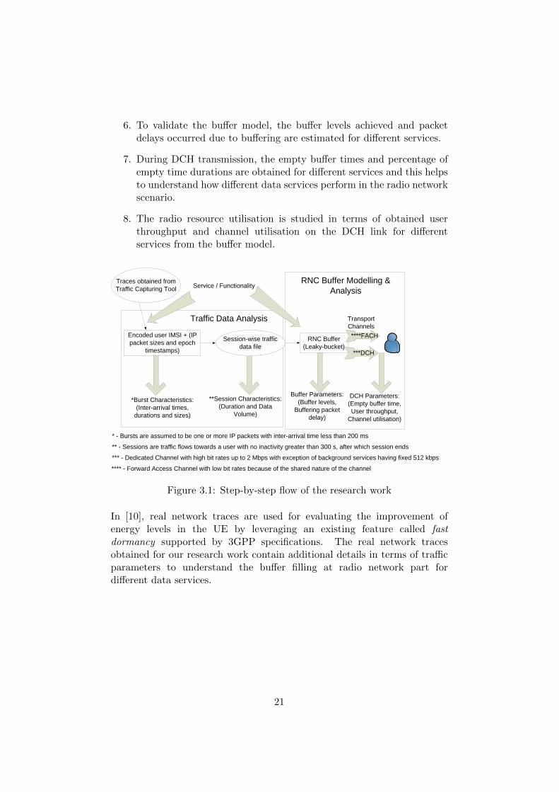
6. To validate the buffer model, the buffer levels achieved and packetdelays occurred due to buffering are estimated for different services.
7. During DCH transmission, the empty buffer times and percentage ofempty time durations are obtained for different services and this helpsto understand how different data services perform in the radio networkscenario.
8. The radio resource utilisation is studied in terms of obtained userthroughput and channel utilisation on the DCH link for differentservices from the buffer model.
Traces obtained from
Traffic Capturing Tool
Encoded user IMSI + (IP
packet sizes and epoch
timestamps)
Service / Functionality
*Burst Characteristics:
(Inter-arrival times,
durations and sizes)
**Session Characteristics:
(Duration and Data
Volume)
Session-wise traffic
data file
RNC Buffer
(Leaky-bucket)***DCH
****FACH
Buffer Parameters:
(Buffer levels,
Buffering packet
delay)
DCH Parameters:
(Empty buffer time,
User throughput,
Channel utilisation)
* - Bursts are assumed to be one or more IP packets with inter-arrival time less than 200 ms
** - Sessions are traffic flows towards a user with no inactivity greater than 300 s, after which session ends
*** - Dedicated Channel with high bit rates up to 2 Mbps with exception of background services having fixed 512 kbps
**** - Forward Access Channel with low bit rates because of the shared nature of the channel
Traffic Data Analysis
RNC Buffer Modelling &
Analysis
Transport
Channels
Figure 3.1: Step-by-step flow of the research work
In [10], real network traces are used for evaluating the improvement ofenergy levels in the UE by leveraging an existing feature called fastdormancy supported by 3GPP specifications. The real network tracesobtained for our research work contain additional details in terms of trafficparameters to understand the buffer filling at radio network part fordifferent data services.
21

Chapter 4
Traffic Data Analysis
The obtained packet traffic data is analysed by classifying the servicesunder their corresponding QoS classes as mentioned before, so as tounderstand the inter-arrival times and packet sizes for different services.Some of the major parameters needed to understand the trafficcharacteristics of different services are also explained in this section.
4.1 Service Distribution
Primarily it is essential to know the amount of each service trafficpresent in the collected traffic data. The sessions considered for differentservices vary in the amount of data transmission and time duration. Asmentioned before, the session ends after 300 s of inactivity. So, the totaldata volume, total number of sessions and total duration of the session areestimated for each service.
Total Data Volume [%]The data volume of a session is calculated by summing up the IP
packet sizes during that particular session. The percentage total datavolume for each service is estimated using the ratio between the total datavolume calculated from all the sessions of a particular service and totaldata volume for all the services present in the trace file.
The percentage of total data volume is calculated so as to ensureclarity in the picture as shown in Figure 4.1. It is evident from Figure 4.1that, almost all the streaming, file-download and web-browsing servicesshow larger data volumes than other services.
Total Number of Sessions [%]The total number of sessions for a service in % is the ratio between the
number of sessions for that particular service and the total number of
22

sessions for all the services. As can be seen from the Figure 4.1,web-browsing, social-networking, instant-messaging and email show acomparatively large number of sessions.
0
20
40
60
80
100
Total Data Volume[%]
Total Number of Session[%]
Total Session Duration[%]
% o
f tot
al
Details of Service Sessions
YouTubeweb-browsingvideo-playbacksoftware-updatesocial-networkingmedia-playbackmapsinstant-messaginggamingfile-sharingfile-download-.*-iTunes-iTunesfile-download-.*-Android-Market-Android-Marketemailaudio-playbackadvertisement
Figure 4.1: Service Distribution
Total Session Duration [%]In addition to the above analysis related to total data volume [%] andtotal number of sessions [%], the total session duration [%] for differentservices is also important. It is calculated from the ratio between theduration of all the sessions of a particular service and total sessionduration of all the services. It is evident from the Figure 4.1 that,web-browsing, social-networking, instant-messaging, email andadvertisement show longer durations of sessions than other services. Thisis similar to that of the total number of sessions [%].
In short, all the streaming, web-browsing, maps and file-downloadservices have shorter session durations and lower number of sessions, buttransmit larger data volume than social-networking, instant-messaging,email and advertisement services.
4.2 IP Packet Characteristics
4.2.1 Packet Sizes [SP]
The characteristics of the traffic flow can be understood from thepacket sizes and inter-arrival times for different services.
23

Figure 4.2 gives an overview of packet sizes in the form of CDF plot,from which almost all GBR streaming services are found to have 80% ofpacket sizes on 1448 bytes, other than media-playback which has varyingpacket sizes between 52 and 1448 bytes.
Figure 4.2: Packet sizes for different services
In case of non-GBR interactive services such as gaming,instant-messaging and social-networking, 60% packet sizes are found to be52 bytes, whereas web-browsing and maps show packet sizes of 1448 bytes
24

for roughly 70% of the values.
So there exists notable diversity within this group and this may be dueto the services such as web-browsing and maps sending large chunks ofdata towards the user. On the other hand, services such asinstant-messaging and social-networking send small chunks of data most ofthe time, when the user is connected to the network and accessing theseservices.
Similar behaviour to that of streaming services is observed in case offile-download and software-update services, whereas advertisement andfile-sharing show packet sizes of 52 bytes in 50% of the values. It isinteresting to look at the file-sharing services, which show small packetsizes probably due to signalling in the network.
4.2.2 Inter-arrival Times [IP]
As can be seen from Figure 4.3, similarities among services in termsof inter-arrival times are observed. It is evident from the Figure 4.3 thatroughly around 70% of inter-arrival times are less than 200 ms for almost allthe services and this implies that there are more packets as bursts, accordingto our assumptions, from the traffic data obtained.
25

Figure 4.3: Inter-arrival times between packets for different services
4.3 Burst Characteristics
It is important to evaluate the characteristics of bursts of packets fordifferent services, before analysing the buffer filling at the radio network,in order to get a clear picture on the data volume sent as packet bursts.This might vary with respect to different services. This analysis has beencarried out based on the assumption of burst inter-arrival times greaterthan 200 ms.
26

Thus the first research question on analysis related to bursts, isaddressed in this section. This deals with the study of bursty behaviour ofpacket arrivals in terms of burst inter-arrival times, durations and sizestaking different services into consideration.
4.3.1 Burst Inter-arrival Times [IB]
The formula used for calculating this value is as follows,
IBn = tBs,n − tBe,n−1 (4.1)
where,IBn - Inter-arrival time of burst n in seconds
tBs,n - Epoch time stamp of first packet or start of current burst
tBe,n−1 - Epoch time stamp of last packet or end of previous burst
It should be noted that, the inter-arrival times between bursts have aminimum value of 200 ms, below which the packets are considered asbursts. In addition, there is a maximum value of 300 seconds, above whichthe session is considered to be terminated and new session will commencewith arrival of packets of the service considered.
It can be observed from Figure 4.4 that GBR-streaming services,interactive services except instant-messaging and background servicesexcept advertisement and file-sharing show most of the inter-arrival timesbetween bursts less than 1 second.
Moreover, instant-messaging and advertisement have roughly 60% ofthe burst inter-arrival times less than 1 second. However in case offile-sharing, there is only 40% of the inter-arrival times are less than 1second.
27

Figure 4.4: Inter-arrival time between bursts for different services
28

advertisement
audio-playback
file-download-.*-Android-Market-Android-Market
file-download-.*-iTunes-iTunes
file-sharing
gaming
instant-messaging
maps
media-playback
social-networking
software-update
video-playback
web-browsing
YouTube
0 2 4 6 8 10 12 14
Ser
vice
s
Inter-Arrival of Bursts [seconds]
Mean Inter-Arrival Time between Bursts
Figure 4.5: Mean Inter-Arrival Time between Bursts
In addition, the mean value of the burst inter-arrivals are calculated withthe confidence intervals as shown in the Figure 4.5, which has most of theservices showing the inter-arrival time roughly around 1 second, which isrelatively high in case of instant-messaging and file-sharing having valuesmore than 5 seconds.
4.3.2 Burst Durations [DB]
It is important to understand the duration of how long the burst existsfor different services, which may be regular or irregular according to the typeof service and also the conditions in the network during data collection. Thisis calculated from the formula,
DBn = tBe,n − tBs,n (4.2)
where,DB
n - Duration of burst n in seconds
tBe,n - Epoch time stamp of last packet or end of current burst
tBs,n - Epoch time stamp of first packet or start of the current burst
From the Figure 4.6, media-playback is found to have short duration ofbursts i.e. less than 1 ms in roughly around 50% of the values. This mightbe because of real-time streaming causing short duration of bursts or
29

individual packet arrivals in case of media-playback.
As shown in Figure 4.6, most of the other services show a duration ofbursts in the range of 200 ms and 1 second, which is observed in more than70% of the bursts for almost all the services except advertisement andsoftware-update, which show around 40% of the burst durations more than1 second.
Figure 4.6: Duration of Bursts for different services
In addition, from the Figure 4.7, the mean and confidence interval
30

implies that most of the services have duration of bursts less than 5seconds, but advertisement and software-update show comparatively longburst durations.
advertisement
audio-playback
file-download-.*-Android-Market-Android-Market
file-download-.*-iTunes-iTunes
file-sharing
gaming
instant-messaging
maps
media-playback
social-networking
software-update
video-playback
web-browsing
YouTube
0 50 100 150 200 250 300
Ser
vice
s
Duration of Bursts [seconds]
Mean Duration of Bursts
Figure 4.7: Average Burst Durations
4.3.3 Burst Sizes [SB]
The constraint that groups the packets m,m+1...m+N in a single burst,is that every packet fulfils the following condition,
tPm+1 − tPm < 200 ms (4.3)
where,tPm+1 - Epoch timestamp of the next packet, in seconds
tPm - Epoch timestamp of the current packet, in seconds
Even though most of the services show almost similar behaviour interms of burst inter-arrivals and durations, the size of bursts are found tovary according to the type of service. This value is calculated as follows:
SBn = SP
m + SPm+1 + · · · + SP
m+N (4.4)
where,SBn - Data Volume or Size of the burst n, in bytes
SPm...SP
m+N - Size of each packet from m to m+N (m+N is the total
31

number of packets in the burst), in bytes
Figure 4.8: Burst sizes for different services
As shown in Figure 4.8, GBR streaming services such as audio andmedia playback show around 80% of the burst sizes in the range of 1448bytes and 10 kB, whereas video-playback is found to have around 80% ofthe burst sizes between 1 kB and 1 MB. The reason behind thischaracteristics emphasizes the larger contents sent as bursts in case of
32
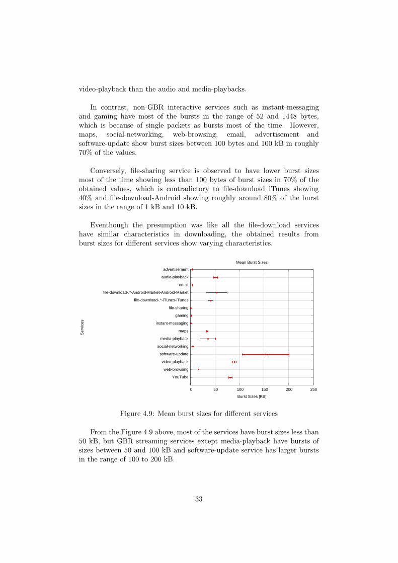
video-playback than the audio and media-playbacks.
In contrast, non-GBR interactive services such as instant-messagingand gaming have most of the bursts in the range of 52 and 1448 bytes,which is because of single packets as bursts most of the time. However,maps, social-networking, web-browsing, email, advertisement andsoftware-update show burst sizes between 100 bytes and 100 kB in roughly70% of the values.
Conversely, file-sharing service is observed to have lower burst sizesmost of the time showing less than 100 bytes of burst sizes in 70% of theobtained values, which is contradictory to file-download iTunes showing40% and file-download-Android showing roughly around 80% of the burstsizes in the range of 1 kB and 10 kB.
Eventhough the presumption was like all the file-download serviceshave similar characteristics in downloading, the obtained results fromburst sizes for different services show varying characteristics.
advertisement
audio-playback
file-download-.*-Android-Market-Android-Market
file-download-.*-iTunes-iTunes
file-sharing
gaming
instant-messaging
maps
media-playback
social-networking
software-update
video-playback
web-browsing
YouTube
0 50 100 150 200 250
Ser
vice
s
Burst Sizes [KB]
Mean Burst Sizes
Figure 4.9: Mean burst sizes for different services
From the Figure 4.9 above, most of the services have burst sizes less than50 kB, but GBR streaming services except media-playback have bursts ofsizes between 50 and 100 kB and software-update service has larger burstsin the range of 100 to 200 kB.
33

4.4 Session Characteristics
4.4.1 Duration of Sessions [DS]
The following analysis is related to understanding the length of sessionsfor different services. From the following Figure 4.10 showing the durationof sessions in minutes, it is evident that almost all the services have mostof their session durations approximately less than 100 minutes.
It is interesting to note that, around 70% of the streaming andfile-sharing services show session durations between 1 and 100 minutes,which is higher than interactive services and background services.
34

Figure 4.10: Durations of Sessions for different services
4.4.2 Data Volume Transmitted per Session [SSA]
For each session the data volume transmitted in kB is calculated bysumming up the IP packet sizes during that session for different services.
From the following Figure 4.11, the GBR streaming services are foundto have 70% of the sessions with data volumes in the range of 10 kB and100 MB.
35

Figure 4.11: Data Volume per Session for different services
Conversely in case of non-GBR interactive services, instant messagingshows around 80% of the sessions with session data volume less than 10kB, followed by gaming and social-networking with 80% session datavolume in the range of 1 kB and 100 kB. However, maps and web-browsingservices show around 60% of the sessions with data volumes between 10 kBand 10 MB.
In case of background services roughly around 80% of the sessions havesession data volumes below 100 kB, other than file-download-Android
36

showing 70% of the sessions having data volume ranging from 1 MB to 10MB, which is observed to transmit highest volumes of data per sessionfrom the obtained traces.
From the analysis related to session data volumes, it is clear thatGBR-streaming services achieve larger data volumes than other services,which may be because of the bulk data sent towards the user during eachsession in terms of streaming services.
4.4.3 Clean Service Traffic Percentage [C S]
It should be noted that the traffic data considered for different services,may possess other services also in the bursts of packets, due tosimultaneous access of different services at the user side.
Moreover, the interest on clean traffic percentage is mainly due toimprove the understanding on how traffic data for different services showclean service packets in the bursts. In other words, there are possibilitiesthat the bursts of packets of a particular service may have a few packetsbelonging to other services.
So, the percentage of packets belonging to a particular service during asession is calculated to understand this value from the obtained trafficdata. Here, the term session has the same definition as mentioned inSection 2.2.2. This also helps us to ensure how reliable different trafficdata from the traces, representing the services under consideration.
This is calculated by finding the ratio between amount of datatransmitted as clean service packets only during a session SS
C and totaldata volume transmitted during the session SS
A.
CS =SSC
SSA
× 100% (4.5)
where,CS - Clean Service Traffic Percentage per session
SSC - Amount of data transmitted as clean service packets per session
SSA - Total data volume transmitted or summation of all packet sizes per
session as explained in Section 4.4.2
So, the higher the value of CS, cleaner the service is. The mean cleanservice traffic percentage is calculated for each service and the 95%
37

confidence interval is plotted in the Figure 4.12 below, showing most of theservices achieve CS greater than 75%.
advertisement
audio-playback
file-download-.*-Android-Market-Android-Market
file-download-.*-iTunes-iTunes
file-sharing
gaming
instant-messaging
maps
media-playback
social-networking
software-update
video-playback
web-browsing
YouTube
0 20 40 60 80 100
Se
rvic
es
Clean Bursts [%]
Percentage of Clean Bursts per User Session
Figure 4.12: Mean Clean Service Traffic Percentage for different services
4.5 Summary
To put it in a nutshell, the traffic data analysis is essential tounderstand the behaviour of the flow of traffic for different services interms of packet sizes, inter-arrival times, bursts and sessions. Some of thepoints to remember from this analysis are as follows:
• Packet sizes obtained from the traces are mostly 52 and 1448 bytes,for which different services share these sizes in different proportions,depending on their corresponding data volume transmitted.
• In case of inter-arrival times, except file-sharing, which hasapproximately 60% of its inter-arrival times greater than 200 ms,other services show lower inter-arrivals than 200 ms most of the timeleading to conclusion that large number of packets are transmitted asbursts of packets with our assumption of 200 ms.
• When it comes to bursty behaviour of the TCP traffic, most of theservices show bursty arrival of packets in 90% of the traces.Furthermore, services such as advertisement, software-update andgaming show higher proportion of mixture of other services also inthe bursts than other services. However, most of the sessionsconsidered for different services show more than 75% clean servicepackets and helpful for analysis on each service separately.
38

• Most of the user sessions considered are found to have their durationsbelow 1 hour, but still there are some sessions which last for longerdurations than an hour.
• The total data volume transmitted to the users during their sessions isdependent on the type of traffic, since different services have varyingsize in the amount of data sent. Thus, there exist relatively high datavolumes in case of streaming and file-download services.
For the subsequent study on buffer filling, the analysis related to burstcharacteristics is of major importance, because it is helpful inunderstanding the traffic data filling buffer, given the inter-arrival timesand sizes of bursts. Moreover, the traffic profiles for different services andtheir properties in terms of several parameters serve the purpose ofdeducing their traffic behaviour in the radio networks in general.
39

Chapter 5
RNC Buffer Modelling
This chapter is organised as follows: Section 5.1 gives an overview on howthe buffer is modelled explaining how the input from the obtained traces ishandled, and an example scenario to understand how the output parametersare estimated from the buffer model. Section 5.2 explains the major designassumptions and approximations made for the buffer model. Section 5.3describes the transitions in the play-out rates of the RNC buffer due to linkbit-rate considerations when there is a switching between channels. Section5.4 is intended to provide the validation of the model by explaining thepossible packet buffering delays and how it conforms with QoS packet delaybudget for different services. Finally, Section 5.5 describes the achievedbuffer levels and its relationship with the burst sizes for different services.
5.1 Trace-Based Simulation Buffer Model
The real network data obtained has been differentiated intosession-wise traffic data files for each service. In addition, as mentionedbefore sessions are active periods containing downlink data traffic for usersunder each service.
From this traffic data, each packet data in terms of epoch timestampand packet size for different services is given as input to the buffer.However, each packet will be serviced according to the bit-rate in thechannel existing at that particular moment of packet arrival.
The UE is considered to be Idle during every session initiation and themajor parameters affecting buffer filling are the channel bit-rates andswitching considerations, which are set as default for our study.Furthermore, according to the 3GPP Release 7 as mentioned in [27] theconditions for channel switching and bit-rates for both dedicated channel(DCH) and forward access channel (FACH) in the pseudo code are
40

as follows:
At the point of a packet arrival,
INITIAL CONDITIONS
If UE is Idle:
Channel = DCH and TransmissionRate = 512 kbps;
If UE is not Idle and Channel == DCH:
TransmissionRate = 512 kbps;
If UE is not Idle and Channel == FACH:
TransmissionRate = 16 kbps;
CHANNEL UPSWITCHING
If UE is not Idle, Channel == FACH and BufferLevel > 512
bytes:
Channel = DCH and TransmissionRate = 512 kbps;
CHANNEL DOWNSWITCHING
If UE is not Idle, Channel == DCH and Emptytime > 3 seconds:
Channel = FACH: TransmissionRate = 16 kbps;
SERVICE-DEPENDENT CHANNEL UPSWITCHING ON QoS
If UE is not Idle and Service is Streaming/Interactive and
TransmissionTime > MaxAccDelay :
TransmissionRate = BufferLevel/MaxAccDelay
where, MaxAccDelay is the maximum acceptable packet delay
caused in the network and acceptable for the user and it
differs for different services. It takes the value of 1
second for streaming and 400 milliseconds for interactive
according to [13] on QoS requirements.
If 512 kbps < TransmissionRate < 1 Mbps:
TransmissionRate = 1 Mbps;
else
TransmissionRate = 2 Mbps.
41

0 1 2 3 4 5 6 7
0 1 2 3 4 5 6 7
A1 A2 A3
D1D2 D3
A4
D4
IP Packet
Arrivals &
Departures
Buffer Filling
Empty
Time
Empty
Time
Buffer
Levels
Packet
Buffering
Delay
0 1 2 3 4 5 6 7
Channel
Switching
User
Throughput
DCH
FACH
Figure 5.1: Calculation of different parameters of the buffer model
As shown in Figure 5.1, if there is an arrival of packet, it will fill thebuffer and gradually the buffer level decreases according to the rate oftransmission through the channel allocated during that particular state ofUE. These buffer levels are important to understand, how different servicesremain in the RNC buffer, given the transmission rates and switchingconditions according to our model. Furthermore, some of the services maycause the buffer levels to increment quickly due to large burst sizes,whereas other services may show low levels due to smaller burst sizes.
Moreover, there may be empty times, during which there are no data inthe buffer and it is measured during DCH transmission only, since theresource allocated during dedicated channel transmission is relatively highand needs optimisation also. On the other hand, FACH transmission isshared and it has low bit-rates and less resource allocation, since manyusers share the channel simultaneously.
In addition, the packet buffering delay is measured using the valueobtained as the difference between the time of arrival of packet in bufferand time of the packet leaving the buffer totally.
This packet buffering delay is an important factor because, the buffershould not take longer time to process the packets, since the end-to-endpacket delays should be within the acceptable limit for delay-sensitiveservices. This has been used for validation of the model and the resultswill be explained in Section 5.4.
In addition, the user throughput is also calculated for different services,
42

during each DCH session for different services, to understand the achievedthroughput in the DCH transmissions. This is estimated from the ratiobetween number of bits transmitted and total time period on DCH.
Additionally, the DCH Utilization has been calculated for every DCHsession according to the channel bit-rate assumptions, which are presentedin Section 6.2.2.
Further explanation on estimation of these parameters in detail withthe help of formulae are given in the following sections with the resultsobtained, when the buffer model is supplied with the real network traces.
5.2 Design Assumptions
For ease of analysis and simplicity, a leaky-bucket buffer model havinga random rate of arrival of packets and deterministic rate of departure ofpackets is chosen. However, the play-out rates set by the buffer depend onUE states as mentioned in Section 5.1.
Packet Arrival
Empty
RNC
Buffer
Move Packet to
RNC buffer
Previous
Packets
Serviced
Wait until previous
packets are serviced
Send Packet
No
Yes
No
Yes
Figure 5.2: Flowchart of RNC buffer model in relation with queueing
As shown in Figure 5.2, the RNC buffer model can be understood as aFirst-In-First-Out (FIFO) queuing model with the play-out bit-rate
43

depending on the channel bit-rate at the moment of packet arrival. Thetime at which the packet is fully serviced is calculated as follows:
tpd = tp−1d + tps (5.1)
where,tpd - Epoch time stamp of the complete packet departure from the buffer, inseconds
tp−1d - Epoch time stamp when the previous packet is serviced (if the
packet arrives at empty buffer, this time is the packet arrival time), inseconds
tps - Time taken to service the packet fully, in seconds
The time taken to service a packet is calculated from the followingformula,
tps =Sp
BCH(5.2)
where,Sp - Packet Size, in bits
BCH - Transmission bit-rate depending on the transport channel allocated,in bps.
5.3 Transport Channels and State Transitions
As mentioned in the Section 2.1.3, the transport channels such as DCHand FACH are allocated by the RNC, to attain data transmission accordingto the data in buffer. As can be seen from the Figure 5.3, there are two modesof operations according to the activity of data transmission through differenttransport channels and the channel switching is dependent on parameterssuch as
• Up-switch Threshold
• Down-switch Timer
• Inactivity Timer
44

512 Kbps
Mode:Idle
CELL_DCH
CELL_FACHDown switch timer:
no traffic for 3
seconds
Up switch threshold: buffer
level > 512 bytes
No traffic for
300 seconds
(Session
Termination)
Up-switch trigger
buffer level > 1 byte
16 Kbps
Mode:Active
1 Mbps
2 Mbps
Inactivity timer:
Packet Buffering Delay >
Maximum Acceptable
Delay ( Up-switch
Streaming & Interactive
only)
Figure 5.3: Switching between transport channels and UE State Transitions
If there is no data transmission between the UE and CN for a while i.e.the UE is Idle and there is a packet arrival, the transport channelprimarily allocated will be DCH, which makes the UE to enter intoCELL DCH state.
During this state, the UE is capable of sending large chunks of datawith good QoS and bit-rates, since the user is allocated with a dedicatedchannel at 512 kbps, which is an assumption on the initial bit-rate for ourstudy. Furthermore, it can reach higher values upto 2 Mbps according tothe packet buffering delay in case of streaming and interactive services.
It should also be noted that, if the data rates are increased, the powerand cost incurred will also be increased accordingly. In 3G, the UE powerconsumption values are found to be around 30 mW in case of power savingmodes such as CELL PCH and URA PCH, 400 mW in case ofCELL FACH and 800 mW in case of CELL DCH state. In other words,CELL FACH state consumes only 50% of power than the CELL DCHstate [18].
However, as FACH is a shared channel among several users, thebit-rate cannot be guaranteed and it is assumed to have 16 kbps bit-rate,and it will be allocated only if the user can be served with low data rates.Yet it can be shifted up to DCH when the buffer level is increased tohigher values than 512 bytes of data.
From the understanding gained from the 3GPP standards Release 9[27], the practical bit-rate assumptions through DCH and FACH has been
45
made.
Moreover the down-switching to FACH from DCH is caused due toexpiry of the down-switching timer, which has 3 seconds as default timervalue in this study. The down-switching from DCH to FACH is consideredto happen after 3 seconds, since longer duration than this value on DCHcould lead to radio resource waste and shorter may lead to excessiveup-switch after premature down-switch i.e. frequent switching.
The UE is considered to be Idle mode, if there are no packet arrivalsfor 300 seconds, which is considered as the termination of the session.
5.4 Effects of Buffering Delays and QoS
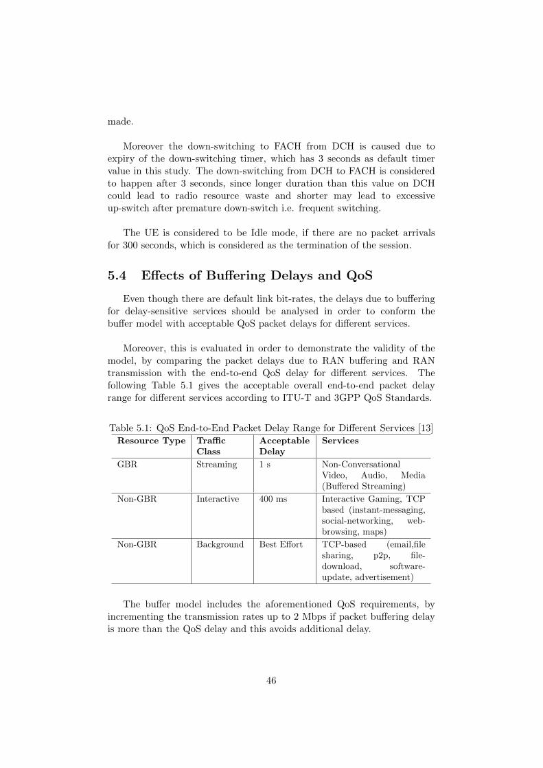
Even though there are default link bit-rates, the delays due to bufferingfor delay-sensitive services should be analysed in order to conform thebuffer model with acceptable QoS packet delays for different services.
Moreover, this is evaluated in order to demonstrate the validity of themodel, by comparing the packet delays due to RAN buffering and RANtransmission with the end-to-end QoS delay for different services. Thefollowing Table 5.1 gives the acceptable overall end-to-end packet delayrange for different services according to ITU-T and 3GPP QoS Standards.
Table 5.1: QoS End-to-End Packet Delay Range for Different Services [13]Resource Type Traffic
ClassAcceptableDelay
Services
GBR Streaming 1 s Non-ConversationalVideo, Audio, Media(Buffered Streaming)
Non-GBR Interactive 400 ms Interactive Gaming, TCPbased (instant-messaging,social-networking, web-browsing, maps)
Non-GBR Background Best Effort TCP-based (email,filesharing, p2p, file-download, software-update, advertisement)
The buffer model includes the aforementioned QoS requirements, byincrementing the transmission rates up to 2 Mbps if packet buffering delayis more than the QoS delay and this avoids additional delay.
46

The packet delay due to buffering is calculated using the following formula,
Bp = (tpd − tpa) × 1000 (5.3)
where,Bp - Packet buffering delay, in milliseconds
tpd - Epoch time stamp when the packet is fully serviced (both waiting andservice), in seconds
tpa - Epoch time stamp when the packet arrives at the buffer, in seconds
With the help of the above formula, the average packet delay due tobuffering for the modelled RNC buffer is calculated for different services.
As shown in the Figure 5.4, almost all the services show packet delaysdue to buffering within the acceptable QoS packet delay budget as shownin Table 5.1, leading to conformance of the valid buffer model havingdefault 512 Kbps DCH, which can go higher upto 2 Mbps if there is a needto send the packets within the acceptable delays and default 16 KbpsFACH, which cannot be varied.
advertisement
audio-playback
file-download-.*-Android-Market-Android-Market
file-download-.*-iTunes-iTunes
file-sharing
gaming
instant-messaging
maps
media-playback
social-networking
software-update
video-playback
web-browsing
YouTube
0 5 10 15 20 25 30 35
Ser
vice
s
Packet Delay on Buffering [milliseconds]
Average Packet Delay due to Buffering
Figure 5.4: Average Buffering Delays for different services
It is also evident from Figure 5.4 that, all the services are found tohave low delays due to buffering at RNC around 20 ms.
In addition, the services such as file-download and software-update
47

showing larger burst sizes in Figure 4.8, are found to have longer delays,which is also considered to ensure the validity of the buffer model.
5.5 Attained Buffer Levels
In addition to the above analysis, it is important to analyse the bufferlevels achieved, due to varying play-out rates. Furthermore, the bufferlevels can be higher for services which need high bandwidth, and also dueto larger bursts and relatively low play-out rates.
Furthermore, these variations have an impact on buffer levels fordifferent services due to this type of link allocation procedure and thefollowing Figure 5.5 shows the variation in buffer levels during downlinkdata transmission for different services.
48

Figure 5.5: Buffer filling levels for different services
From the Figure 5.5, it is evident that around 80% of the buffer levelsfor GBR streaming services except media-playback is between 1 kB and1 MB.
Similarly in case of non-GBR interactive services such as web-browsingand maps around 90% of the buffer levels are in the same range as that ofstreaming services.
Conversely, non-GBR interactive services such as gaming,
49

instant-messaging and social-networking are observed to achieve bufferlevels of around 52 B in around 50% of the values, which implies thatmostly the packets arrive at an empty buffer as single 52 B packet. Similarcharacteristics are found in case of non-GBR background services such asadvertisement, email and file-sharing showing around 70% of the bufferlevels less than 1448 B.
On the other hand, non-GBR background services such asfile-download and software-update show around 80% of the buffer levelsbetween 1 MB and 10 MB.
Furthermore, the following Figure 5.6 shows the average buffer levels inMega-Bytes for different services, giving the mean value and its confidenceintervals.
As can be seen from Figure 4.8, the services such as file-download andsoftware-update showing larger burst sizes, are found to have higher bufferlevels as shown in Figure 5.5 than other services. This is considered asvalidation of the results obtained from the model.
advertisement
audio-playback
file-download-.*-Android-Market-Android-Market
file-download-.*-iTunes-iTunes
file-sharing
gaming
instant-messaging
maps
media-playback
social-networking
software-update
video-playback
web-browsing
YouTube
0 2 4 6 8 10 12 14
Ser
vice
s
Average Buffer Level [MB]
Mean Buffer Level Achieved
Figure 5.6: Average buffer levels for different services
5.6 Summary
As can be understood from the above modelling and analysis of the RNCbuffer:
50

• The RNC buffer modelled has no maximum limit and considered tobe of a leaky-bucket model having random rate of packet arrivals anddeterministic play-out rates with default setting of 512 Kbps throughDCH and 16 Kbps through FACH. However, in case of delay-sensitiveservices, the rates can be incremented upto 2 Mbps, when transmissionis through DCH. This is performed by tracking the buffer levels andtransmission time taken to service the packets arrived at the buffer fordifferent services.
• From the observations made after supplying the obtained traffic dataas input to the modelled buffer, it is evident that all the services incurpacket delays at RAN lower than the acceptable limit according toend-to-end QoS packet delay budget set for 3G and LTE network fordifferent services [13], indicating the validity of the buffer model forthe study involved.
• The buffer levels achieved by different services are comparatively highin case of non-GBR background services such as email, file-downloadand software-update in increasing order.
• The buffer levels are estimated to understand the validity of the resultswith the help of input data. It is observed that services having largebursts as shown in Figure 4.8 are found to have higher buffer levels asshown in Figure 5.5 than other services and this is considered to be avalidation check for the buffer model and the results obtained.
51

Chapter 6
Results and Discussion
In Chapter 4, the characteristics of traffic data supplied as input to theleaky-bucket RNC buffer model and in Chapter 5, the assumptions andapproximations made in modelling the RNC buffer are covered.Furthermore on the analysis made, there are some important results,which address the research questions framed in the Chapter 3.
The analysis is performed step by step for each service by focussing oncertain important parameters of the buffer model with channel bit-rateassumptions.
This chapter is organised as follows: Section 6.1 explains the obtainedempty buffer durations during DCH transmission for different services,Section 6.2 comparatively illustrates the performance of different servicesin terms of user throughput and dedicated channel utilisation for differentservices, Section 6.3 discusses the overall results for different services withthe help of obtained parameters from the buffer model and Section 6.4summarises the validity of the results obtained.
6.1 Idle buffer Characteristics during DedicatedChannel Transmission
Due to irregular arrivals of packets for different services, there occursintermittent time intervals during which there are no data transmission tothe user from the radio network. This in turn causes down-switching fromDCH to FACH, which takes place only when the down-switch timerexpires.
It should be noted that DCH session signifies the duration of the users’presence in the dedicated channel with infinite active time and finite timeto stay on DCH during inactivity for about 3 seconds, after which
52

down-switching happens. This value is an assumption, which is found tobe valid in most of the networks.
Due to varying characteristics of data services in 3G networks, for somedata services, during DCH transmission, there may be empty times inbuffer, making the resources occupied by the user but no data transmissionduring those periods.
The second research question is addressed in this section, by analysingthe emptiness of buffer during DCH transmission for different services andthe percentage of empty buffer duration observed from the total DCHsession duration.
6.1.1 Empty Buffer Duration [De]
In this section, the variations in the empty buffer times for differentservices are analysed, during which no data is present in the buffer duringDCH transmission, but the radio resources allocated for the user are stilloccupied. This value is calculated using,
De = tds − tbe (6.1)
where,De - Empty Buffer Duration in seconds
tds - Epoch time when down-switching occurs from DCH to FACH duringeach DCH session
tbe - Epoch time when buffer becomes empty during DCH session
As shown in the following Figure 6.1, most of the services have idlebuffer behaviour for roughly 200 milliseconds duration, which can bemaximum up to 3 seconds as can be seen in some cases, after which thereis a channel down switching to shared channel FACH.
53

Figure 6.1: Idle Durations of Buffer during DCH transmission
Furthermore, almost all the services have short empty times less than500 ms in most of the cases. This might be helpful in avoiding frequentdown-switching, but if there are a lot of short empty times, there arepossibilities that the channel may not be used to its full potential.
The following Figure 6.2 shows the average value on empty buffertimes, from which it is clear that almost all the services have a meanempty buffer duration of about 500 milliseconds, a bit higher in case ofgaming, software-update and advertisement reaching roughly around 700
54

milliseconds.
advertisement
audio-playback
file-download-.*-Android-Market-Android-Market
file-download-.*-iTunes-iTunes
file-sharing
gaming
instant-messaging
maps
media-playback
social-networking
software-update
video-playback
web-browsing
YouTube
0 0.1 0.2 0.3 0.4 0.5 0.6 0.7 0.8 0.9
Ser
vice
s
Average Empty Buffer Time [seconds]
Mean Idle Buffer Time
Figure 6.2: Average Idle Durations of Buffer during DCH transmission
It should be noted that, the channel down-switching happens only whenthe down-switching timer expires. So, most of the services do not show largenumber of empty times showing maximum value i.e., 3 seconds. However,in the DCH, there occurs empty duration of around 500 milliseconds, whichis observed in most of the services.
6.1.2 Percentage of Emptiness in Buffer per DCH Session[Pe]
The following calculation is performed for each DCH session by findingthe ratio between the total empty buffer duration and the total DCHsession duration like,
Pe =Dt
e
DDCH× 100 (6.2)
where,Pe - Empty Buffer Percentage per DCH session
Dte - Total empty buffer duration during the DCH session
DDCH - Total time duration of the DCH session
55

The following Figure 6.3, gives the percentage of these values for eachservice, which shows that, most of the empty buffer percentage values aremore than 80% of the total duration for almost all the services exceptvideo-playback and file-download-Android, because of numerous emptytimes of buffer during a DCH session. However, around 60% and 75% ofthe empty percentage values are below 75% for video-playback andfile-download-Android, respectively.
Figure 6.3: Empty Buffer Percentage during DCH sessions
As shown in Figure 6.4, it is evident that the mean empty buffer
56

percentage value is around 90% for most of the services, exceptfile-download-Android, which only shows about 40% of the DCH sessionwith empty RNC buffer, followed by video-playback showing 60% emptypercentage.
advertisement
audio-playback
file-download-.*-Android-Market-Android-Market
file-download-.*-iTunes-iTunes
file-sharing
gaming
instant-messaging
maps
media-playback
social-networking
software-update
video-playback
web-browsing
YouTube
0 10 20 30 40 50 60 70 80 90 100
Ser
vice
s
Average Empty Buffer Duration [%]
Mean Idle Buffer Duration per DCH Session
Figure 6.4: Average Empty Buffer Percentage during DCH sessions
It is interesting to observe the empty buffer duration percentage ineach DCH session, because due to intermittent short gaps between arrivals,there occurs more short empty times in the buffer causing high emptybuffer percentage during DCH session for most of the services.
6.2 Radio Resource Utilisation in terms ofDedicated Channel Performance
From the above analyses related to RNC buffer behaviour, it is evidentthat most of the services have short gaps between arrivals less than 500 mscausing empty buffer during most of the DCH sessions.
It should be noted that, it incurs more power, RNC cost and resources,when the DCH channels are occupied and the users are inactive duringtheir DCH session.
This section addresses the third research question, which involvesunderstanding the user throughput and transport channel utilisationduring DCH transmission according to our buffer model assumptions and
57

obtained traffic data.
6.2.1 Achieved User Throughput on DCH [Ta]
The throughput achieved per DCH session is termed as userthroughput and the maximum achievable is limited to 2 Mbps because ofradio link bit-rate limitations as described in 3GPP Release 7 [27], whichcan be less than that for pure best effort services. The Ta values are foundusing the equation,
Ta =BDCH
DDCH(6.3)
where,Ta - Achieved User Throughput during the DCH session
BDCH - No. of bits transmitted per DCH session
DDCH - Total duration of the DCH session
It should be noted that, Figure 6.5 has throughput values in Mbps onits x-axis, which can have maximum value of 2 Mbps on DCH.
As can be seen from Figure 6.5, GBR streaming services other thanvideo-playback have throughput values around 128 Kbps, whereasvideo-playback is found to have around 60% of the throughput between128 kbps and 1 Mbps.
On the other hand, non-GBR interactive services show throughputvalues less than 64 Kbps during most of the DCH sessions, which is similarto almost all the non-GBR background services. However,file-download-Android show higher throughput values than any otherservices, with roughly around 60% of the DCH sessions with maximum 512kbps throughput.
It should also be noted that, the maximum channel bit-rate is 512 kbpsin case of non-GBR background services, whereas it can be switched up to1 Mbps or 2 Mbps, when the transmission time for a packet to be fullyserviced is more than the acceptable QoS delay for different services asshown in Table 5.1. This is evident from the Figure 6.5.
58

Figure 6.5: Achieved Throughput on DCH transmission
The following Figure 6.6 shows that most of the services other thanGBR streaming and file-download-Android services, have an average userthroughput less than 128 kbps.
59
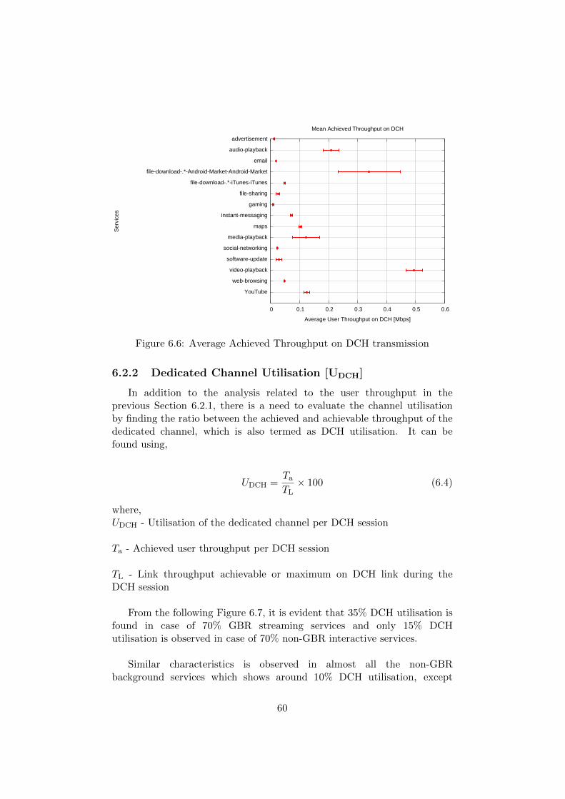
advertisement
audio-playback
file-download-.*-Android-Market-Android-Market
file-download-.*-iTunes-iTunes
file-sharing
gaming
instant-messaging
maps
media-playback
social-networking
software-update
video-playback
web-browsing
YouTube
0 0.1 0.2 0.3 0.4 0.5 0.6
Ser
vice
s
Average User Throughput on DCH [Mbps]
Mean Achieved Throughput on DCH
Figure 6.6: Average Achieved Throughput on DCH transmission
6.2.2 Dedicated Channel Utilisation [UDCH]
In addition to the analysis related to the user throughput in theprevious Section 6.2.1, there is a need to evaluate the channel utilisationby finding the ratio between the achieved and achievable throughput of thededicated channel, which is also termed as DCH utilisation. It can befound using,
UDCH =Ta
TL× 100 (6.4)
where,UDCH - Utilisation of the dedicated channel per DCH session
Ta - Achieved user throughput per DCH session
TL - Link throughput achievable or maximum on DCH link during theDCH session
From the following Figure 6.7, it is evident that 35% DCH utilisation isfound in case of 70% GBR streaming services and only 15% DCHutilisation is observed in case of 70% non-GBR interactive services.
Similar characteristics is observed in almost all the non-GBRbackground services which shows around 10% DCH utilisation, except
60

file-download Android, which shows approximately around 90% DCHutilisation in most of the cases.
Figure 6.7: Utilisation of Dedicated Channel for different services
However, in a few cases there is 100% utilisation also observed in someof the services. But comparatively the proportion is low and according tothe assumed channel bit-rate and switching conditions, poor utilisation ofthe channel is observed in most of the cases.
61

advertisement
audio-playback
file-download-.*-Android-Market-Android-Market
file-download-.*-iTunes-iTunes
file-sharing
gaming
instant-messaging
maps
media-playback
social-networking
software-update
video-playback
web-browsing
YouTube
0 20 40 60 80 100
Ser
vice
s
Average DCH Utilisation [%]
Mean Utilisation of DCH
Figure 6.8: Average Utilisation of Dedicated Channel for different services
This is a matter of concern, when it comes to resource optimisation inthe radio networks in terms of DCH channel allocation. Furthermore, theaverage utilisation levels of DCH for different services from the Figure 6.8also show that most of the services, except file-download-Android andvideo-playback show average DCH utilisation less than 20%.
6.3 Discussion of the Results
From the statistical analysis with the obtained real network traces andtheir behaviour from the buffer model, the following results are implied:
• For almost all the services, the burst size and duration depend on thetype and content abundance of the particular service. Longerdurations of bursts are seen in advertisement and software-updateservices and larger bursts are found in most of the GBR streaming,file-download and software-update services.
• Short empty buffer times are observed during DCH sessions fordifferent services and most of their values are below 500 milliseconds,but the percentage of total empty time duration to a DCH sessionduration is around 80% for most of the services.
• The user throughput values are found to have significantly lowervalues than the achievable throughput of the channel and in turn theDCH utilisation is also found to achieve lower values for most of the
62

services, which is suboptimal when it comes to effective radioresource utilisation.
6.4 Validity of the Results
As a general idea, a methodology to study the RNC buffer characteristicsand DCH channel utilisation has been proposed, which persuaded us toconclude that there exists undesirable resource utilisation with respect totransport channel allocation and overall performance of different services.
• Bit-Rate Assumptions
– It should be noted that the results are valid only for the conditionsassumed in terms of bit-rate conditions in the DCH and FACHchannels.
– In order to avoid congestion at the RAN, the mobile operatorshave to consider a fair network policy control framework. Thisdiffers from one operator to another, since the priorities mightvary for the services among different operators. In addition, itmay be the time-sensitive data getting higher priority than thenon-time-sensitive data or delivery of normal users’ data moreimportant than the heavy users’ data or the service for providingfor premium subscribers’ data might be more important than thebasic subscribers’ data.
– However, the bit-rates exhibited in the real network during packetcapturing are not known and so the RNC buffer model is studiedunder default channel assumptions as understood from [27] andthe results are observed and analysed.
– In addition, the buffer model using this assumption, analysesevery single user and his/her service access and no multiple userscenarios are considered simultaneously, since this study isaimed at providing characteristics of different services at theradio network with respect to single user traffic flow.
– The real transmission conditions were remodelled for theassumptions made for the study and this might be different inreal network scenario. However, the study is mainly aimed atanalysing the traffic data obtained and understanding the bufferfilling for that particular kind of traffic profiles, with channeltransmission assumptions.
• Channel Switching AssumptionsFurthermore, channel switching considerations in terms ofup-switching threshold (in bytes) and down-switching timer (in
63

seconds) are assumptions based on understanding related to optimalchannel switching and processing overhead under the sensitivityanalysis. The results might vary, if these values are varied.
• Dataset VariationsThe obtained real network traces are large and it is captured from asingle 3G network. Even if the dataset is varied, similarities in thetraffic characteristics for different services analysed would be observedin most of the cases, since numerous sessions of traffic are consideredfor each service from the obtained traffic.
64

Chapter 7
Conclusion and Future Work
In this thesis work, the major analysis carried out is related to thebuffer filling in the RNC for different services and in accordance with thetransport channel transitions, the performance of different services in theradio network is studied.
7.1 Conclusion
From the collective analysis of different service traffic, it is important toachieve necessary understandings from the results obtained, so as to addressthe research questions. This section compares the research questions withthe obtained outcomes as follows:
• RQ 1: What are the variations in terms of inter-arrivals, durationsand sizes of bursts of IP packets for different services?
– Most of the bursts of packets have mean inter-arrival time of lessthan 2 seconds, except file-sharing and instant-messaging, whichhave mean inter-arrival time of 5 and 10 seconds respectively.
– The mean duration of bursts is found to vary around 200milliseconds for most of the services, other than advertisementand software-update services, which have longer burst durations.
– Only some of the services such as GBR streaming, file-downloadand software-update have large burst sizes of around 50 to 200kB, which is larger than most of the other services such asnon-GBR interactive and non-GBR background servicesshowing mean burst sizes less than 50 kB.
• RQ 2: How long does the RNC buffer show empty buffer levels duringDCH transmission for different services?
65

– From the analysis made on buffer filling levels, the meanduration of empty buffer during DCH transmission is found tovary around 400 milliseconds for most of the services, except theGBR streaming services, that show shorter mean empty times.
– In case of almost all the services, the highest percentage ofempty buffer levels during DCH session is found to be around80%, during which there is no data reception or transmission atthe RAN, but the resources are still allocated to the users,incurring undesirable cost and power for the RNC.
– However, file-download-Android and video-playback are found toshow better buffer performance than other services, by achievingsmaller empty buffer percentages less than 40%.
• RQ 3: How do different services perform on dedicated channel datatransmission in terms of user throughput and channel utilisation?
– The average buffer levels observed in the RNC are less than 1 MBfor most of the services except file-download and software-updateservices.
– In addition, the average achieved user throughput show generallylow values for most of the services, which is not optimal.
– Consecutively, utilisation of dedicated channel is found to bearound 30% for most of the services, raising a question oneffective switching and state considerations in radio accessnetwork for data services.
Furthermore, these services are widely-used services and have crucialimpact on the radio network utilisation and there is a need to analysesolutions to eliminate this problem, with the perspective of radio resourceoptimisation.
In addition, the transport channel requirements for different servicesmay vary and a better solution would be to track the services and providethe channel allocation to eliminate unwanted utilisation of channels, whichwill be helpful in allocating unused channels to other users. However, thismight additionally increase the overhead and incur more delays due tochannel switching.
7.2 Future Work
The potential future work of this research can be related tounderstanding further, the cost and resource utilisation in terms of channelswitching between DCH and FACH, taking different services into
66

consideration. In addition, there is a need to deeply understand the bufferbehaviour, with the inclusion of real network cell considerations likeheavily loaded, medium loaded and lowly loaded network scenario,containing multiple users scenario and test cases and its impacts on theresource utilisation.
In order to improve the buffer model further, the capacity or bit-ratesof the channels such as DCH and FACH can be increased further until thelarge backlogs or data volumes in the buffer for some services such assoftware update vanishes. However, this may further complicate the modelwith varying bit-rates for each service according to their data volumeunderstood from the traffic data obtained.
Furthermore, the switching conditions, which have been assumed witha specific value can be varied to understand the optimum value ofswitching for each service under which there may be possibilities ofachieving fair utilization of the channel. However, the switching may haveto be compromised with the cost and delays occurred if there are frequentswitching.
From the results obtained, the study can be extended further withanalytical modelling with fluid-flow models and this will help us tounderstand the traffic parameters and their regularities or irregularities fordifferent services.
Moreover, the RRM functions such as handover and powermanagement functionalities in the buffer model would help to understandthe buffer filling for different traffic scenarios and accordingly from theseresults packet scheduling can be performed at the CN in order to increasethe channel utilisation for different services.
In fact, the same kind of real of network traces can be used for theanalysis with an enhanced buffer model consisting of different load scenarioand RRM functionalities to study the performance of different servicesaccording to different kinds of network considerations.
67

Bibliography
[1] 3GPP TS 23.107, ”Universal Mobile TelecommunicationsSystem(UMTS); Quality of Service (QoS) concept and architecture.”
[2] 3GPP TS 23.401, ”General Packet Radio Service (GPRS) Enhancementsfor Evolved Universal Terrestrial Radio Access Network (E-UTRAN)Access.”
[3] 3GPP TS 34.108, ”3rd Generation Partnership Project; TechnicalSpecification Group RAN; Delay Budget within the Access Stratum.”
[4] 3GPP TS 36.300, ”Evolved Universal Terrestrial Radio Access (E-UTRA) and Evolved Universal Terrestrial Radio Access Network (E-UTRAN):Overall Description.”
[5] 3GPP TS 36.331, ”Evolved Universal Terrestrial Radio Access Network(E-UTRAN); Radio Resource Control (RRC);Protocol Specification.”
[6] 3GPP TS 36.413, ”Evolved Universal Terrestrial Radio Access Network(E-UTRAN); S1 Application Protocol.”
[7] E. Dahlman, S. Parkvall, J. Skold and P. Beming, 3G Evolution: HSPAEvolution and LTE for Mobile Broadband, 2nd Edition, Academic Press,2008.
[8] W. L. Tan, F. Lam and W. C. Lau, ”An Empirical Study on theCapacity and Performance of 3G Networks,” IEEE Transactions onMobile Computing, vol. 7, no. 6, pp. 737-750, June 2008.
[9] Z. Zhu, G. Cao, R. Keralapura and A. Nucci, ”Characterizing DataServices in a 3G Network: Usage, Mobility and Access Issues”, IEEEInternational Conference on Communications, pp. 1-6, June 2011.
[10] F. Qian, Z. Wang, A. Gerber, Z. Morley Mao, S. Sen andO. Spatscheck, ”Characterizing Radio Resource Allocation for 3GNetworks”, International Mobile Conference, Nov 2010.
[11] R. Mayank Kumar, ”Developing a QoS Aware Framework for LTE, QoSControl and QoS Aware Scheduler”, Aricent White Paper, July 2012.
68

[12] A. Sang, X. Wang and M. Madihian, ”Differentiated TCP UserPerception over Downlink Packet Data Cellular Systems,” IEEETransactions on Mobile Computing, vol. 6, no. 3, pp. 252-263, March2007.
[13] ITU-T Y.1541, ”Network performance objectives for IP-based services”.
[14] S. Yang and Y. Lin, ”Modeling UMTS Discontinuous ReceptionMechanism”, IEEE Transactions on Wireless Communications, vol. 4,no. 1, January 2005.
[15] J. J. Alcaraz, F. Cerdan and J. Garcia-Haro, ”Optimizing TCP andRLC interaction in the UMTS radio access network,” IEEE Network,vol. 20, no. 2, pp. 56-64, March-April 2006.
[16] Y. Ohta, K. Kawahara, T. Ikenaga and Y. Oie, ”Performance evaluationof channel switching scheme for packet data transmission in RadioNetwork Controller”, IEICE Transactions on Communications, vol.E87B, No. 5, pp. 1141-1150, May 2004.
[17] A. Alexiou, C. Bouras and V. Igglesis, ”Performance Evaluation of TCPover UMTS Transport Channels”, 2008.
[18] L. Wang, A. Ukhanova and E. Belyaev, ”Power consumption analysis ofconstant bit rate data transmission over 3G mobile wireless networks”,11th International Conference on ITS Telecommunications, pp. 217 -223,August 2011.
[19] R. Bestak, P. Godlewski and P. Martins, ”RLC buffer occupancy whenusing a TCP connection over UMTS”, The 13th IEEE InternationalSymposium on Personal, Indoor and Mobile Radio Communications, vol.3, pp. 1161-1165, September 2002.
[20] J. J. Alcaraz, G. Pedreo, F. Cerdan and J. Garcia-Haro, ”Simulationof 3G DCHs supporting TCP traffic: design, experiments and insightson parameter tuning,” Proceedings of the 1st international conferenceon Simulation tools and techniques for communications, networks andsystems, Article 75, 8 pages, March 2008.
[21] P. H. J. Perala, A. Barbuzzi, G. Boggia and K. Pentikousis, ”Theoryand Practice of RRC State Transitions in UMTS Networks,” IEEEGLOBECOM Workshops, pp. 1-6, Nov-Dec 2009.
[22] F. Qian, Z. Wang, A. Gerber, Z. M. Mao, S. Sen and O.Spatscheck, ”TOP: Tail Optimization Protocol For Cellular RadioResource Allocation,” 18th IEEE International Conference on NetworkProtocols (ICNP), pp. 285-294, Oct. 2010.
69

[23] W. Featherstone, J. P. Wallington and F. Schneider, ”TCP PerformanceOver UMTS Dedicated Channels with Finite RLC Buffer Size”, 6th IEEInternational Conference on 3G and Beyond, pp. 1-5, November 2005.
[24] H. Van Peteghem and L. Schumacher, ”UMTS Non Real-Time SessionsChannel Switching Emulation”, IEEE 65th Vehicular TechnologyConference, pp. 1061-1065, April 2007.
[25] A. Larmo, ”Usability of Instant Messaging over WCDMA”, M. S.Thesis, Helsinki University of Technology, Finland, 2005.
[26] J. J. Alcaraz and F. Cerdan, ”Using buffer management in 3G radiobearers to enhance end-to-end TCP performance,” 20th InternationalConference on Advanced Information Networking and Applications, vol.2, pp. 5, April 2006.
[27] H. Holma and A. Toskala, WCDMA for UMTS - HSPA evolution andLTE, 4th Edition, John Wiley and Sons, 2002.
70

Appendix
71

Appendix A
Sub-types of Services
• unknown
• SSL
• HTTP-web-browsing
• HTTP
• maps-HTTP-Google
• file-download-HTTP-iTunes-iTunes
• video-playback-HTTP-YouTube-iPhone-Media-Player
• social-networking-HTTP-Facebook
• blackberry
• DNS-system
• web-browsing-HTTP-Google
• video-playback-HTTP-iPhone-Media-Player
• Google-SSL
• audio-playback-HTTP-Apple-iPhone-Media-Player
• email-IMAP-SSL
• email-POP3-SSL
• HTTP-audio-playback
• video-playback-HTTP-YouTube-Android-Media-Player
72

• HTTP-video-playback
• email-IMAP-SSL-Google
• POP3-email
• social-networking-HTTP-Facebook-Facebook
• FB1-AKAMAI
• HTTP-iPhone-Media-Player
• video-playback-HTTP-YouTube-Internet-Explorer
• instant-messaging-SSL-Google-GTalk
• web-browsing-HTTP-YouTube-iPhone-Media-Player
• web-browsing-HTTP-YouTube-YouTube-player
• web-browsing-HTTP-Chrome
• HTTP-Google
• web-browsing-HTTP-Mozilla-Firefox
• XMPP-instant-messaging
• video-playback-HTTP-YouTube
• web-browsing-HTTP-Internet-Explorer
• audio-playback-HTTP-iTunes-iTunes
• media-playback-RTP-Google
• audio-playback-Spotify-Spotify-Spotify
• advertisement-HTTP-Google
• audio-playback-HTTP-iPhone-Media-Player
• web-browsing-HTTP-Apple-Internet-Explorer
• HTTP-MMS
• FB2-AKAMAI
• file-download-HTTP-Android-Market-Android-Market
• HTTP-SSL
• IMAP-email
73

• web-browsing-HTTP-YouTube-Internet-Explorer
• software-update-HTTP-Microsoft-Microsoft-Windows
• ICMP-system
• web-browsing-HTTP-Apple-Mozilla-Firefox
• IPSec-NAT-traversal-IPSec-NAT-traversal
• software-update-HTTP-Symantec-Symantec
• web-browsing
• HTTP-Apple
• video-playback-HTTP-YouTube-Mozilla-Firefox
• FB3-AKAMAI
• social-networking-HTTP-Twitter-Twitter
• instant-messaging-Google-GTalk
• web-browsing-HTTP-YouTube-Android-Media-Player
• social-networking-HTTP-Twitter
• FTP-file-sharing
• RTMP-media-playback
• video-playback-HTTP-Mozilla-Firefox
• video-playback-HTTP-Internet-Explorer
• web-browsing-HTTP-iPhone-Media-Player
• maps-HTTP-Google-GoogleEarth
• advertisement-HTTP-AdMob
• web-browsing-HTTP-Google-Internet-Explorer
• email-SMTP-Google
• SMTP-email
• web-browsing-HTTP-YouTube
• web-browsing-HTTP-SSL
• social-networking-HTTP-Facebook-Chrome
74

• web-browsing-HTTP-Google-Mozilla-Firefox
• video-playback-HTTP-Chrome
• video-playback-HTTP-YouTube-Chrome
• web-browsing-HTTP-megavideo-Mozilla-Firefox
• Windows-system
• advertisement-HTTP-Flurry
• RTSP-media-playback
• web-browsing-HTTP-Google-Chrome
• web-browsing-HTTP-YouTube-Chrome
• web-browsing-HTTP-Apple
• video-playback-HTTP-Apple-iPhone-Media-Player
• UPnP-system
• HTTP-weather
• social-networking-HTTP-Facebook-Internet-Explorer
• advertisement-HTTP-Google-Internet-Explorer
• email-SMTP-SSL-Google
• social-networking-HTTP-Facebook-Mozilla-Firefox
• HTTP-maps
• advertisement-AKAMAI-Google-FB3
• instant-messaging-XMPP-Google
• web-browsing-HTTP-YouTube-Mozilla-Firefox
• HTTP-Android-Market-Android-Market
• web-browsing-HTTP-Apple-iPhone-Media-Player
• instant-messaging-HTTP-Yahoo
• audio-playback-HTTP-Internet-Explorer
• advertisement-HTTP-Google-Mozilla-Firefox
• RTP-media-playback
75

• video-playback-HTTP-Google
• email-POP3-SSL-Google
• RTP-Google
• email-HTTP-Yahoo
• gaming-HTTP-KaW
• instant-messaging-HTTP-KakaoTalk
• social-networking-HTTP-Xiaonei
• social-networking-HTTP-Weibo
• instant-messaging-XMPP-SSL
• social-networking-HTTP-Twitter-Mozilla-Firefox
• gaming-HTTP-WordsWithFriends
• web-browsing-AKAMAI
• HTTP-SSL-Apple
• web-browsing-HTTP-Tencent-QQ
• advertisement-HTTP-Google-Chrome
• instant-messaging-GTalk
• web-browsing-Opera-Mini-sockets-Opera-Mini
• email-SMTP-SSL
• social-networking-HTTP-SSL-Facebook
• photo-sharing-HTTP-Flickr
• software-update-HTTP-Flurry-Skype
• LLMNR-system
• HTTP-YouTube
• web-browsing-Mozilla-Firefox
• video-playback-HTTP-Tencent-QQ
• NTP-system
• web-browsing-AKAMAI-Apple
76

• audio-playback-HTTP-Windows-Media-Player
• HTTP-Internet-Explorer
• social-networking-HTTP-SSL-Twitter-Twitter
• web-browsing-YouTube
• social-networking-HTTP-Myspace
• web-browsing-HTTP-Baidu
• media-playback-RTSP-Google
• HTTP-iTunes-iTunes
• web-browsing-HTTP-Baidu-Chrome
• FB4-AKAMAI
• software-update-HTTP-Installous
• software-update-HTTP-Telesphoreo
• gaming-HTTP-Flurry-WordsWithFriends
• SIP
• web-browsing-Internet-Explorer
• social-networking-HTTP-Twitter-Internet-Explorer
• software-update-HTTP-Skype
• gaming-HTTP-Smurfs
• social-networking-HTTP-YouTube-Twitter
• instant-messaging-Tencent-QQ
• web-browsing-Chrome
• file-download-HTTP-SSL-iTunes-iTunes
• IGMP-system
• HTTP-AppleDaily
• web-browsing-AKAMAI-Internet-Explorer
• social-networking-HTTP-SSL-Twitter
• social-networking-HTTP-Twitter-Chrome
77

• media-playback-RTMP-HTTP
• web-browsing-AKAMAI-Chrome
• HTTP-speedtest
• instant-messaging-HTTP-Viber-Viber
• advertisement-HTTP-YouTube
• maps-HTTP-Tencent-QQ
• instant-messaging-HTTP-Fring
• web-browsing-AKAMAI-Apple-Mozilla-Firefox
• instant-messaging-XMPP-SSL-Google
• gaming-HTTP-TeamLava-Storm8
• STUN-system
• FB1-SSL-AKAMAI
• web-browsing-Apple
• web-browsing-AKAMAI-Mozilla-Firefox
• advertisement-Google
• gaming-HTTP-SSL-WordsWithFriends
• FB2-SSL-AKAMAI
• web-browsing-Google
• instant-messaging-HTTP-Google-WhatsApp
• AKAMAI-YouTube-FB1
• DHCP-system
• AKAMAI-YouTube-FB3
• social-networking-HTTP-Flurv
• instant-messaging-HTTP-WhatsApp
• email-HTTP-iPhone-Mail
• advertisement-HTTP-SSL-Google
• maps-HTTP-SSL-Apple
78

• software-update-HTTP-Apple-Installous
• email-HTTP-Yahoo-Mozilla-Firefox
• instant-messaging-HTTP-Apple-WhatsApp
• Apple-AKAMAI
• social-networking-HTTP-Facebook-Opera
• weather-HTTP-Google
• instant-messaging-HTTP-Nimbuzz-Nimbuzz
• video-playback-HTTP-YouTube-YouTube-player
• HTTP-Mozilla-Firefox
• gaming-HTTP-Facebook-WordsWithFriends
• software-update-HTTP-Adobe-Adobe-Update-Manager
• video-playback-HTTP-Tencent-QQ-iPhone-Media-Player
• advertisement-HTTP-Google-YouTube-player
• instant-messaging-SSL-Tencent-QQ
• maps-HTTP-Apple
• instant-messaging-MSN
• email-HTTP-Google
• web-browsing-HTTP-Opera
• WAP-MMS
• social-networking-Twitter-Twitter
• SSH-remote-access
• social-networking-HTTP-SSL-Facebook-Facebook
• WAP-web-browsing
• email-HTTP-SSL-Google
• gaming-HTTP-TeamLava
• advertisement-AKAMAI-Google-FB2
• video-playback-HTTP-Google-Internet-Explorer
79

• HTTP-Tencent-QQ
• web-browsing-Google-Mozilla-Firefox
• social-networking-HTTP-Facebook-iPhone-Media-Player
• instant-messaging-AOL
• web-browsing-HTTP-SSL-Apple
• weather-HTTP-Internet-Explorer
• maps-HTTP-SSL-Google
• instant-messaging-HTTP-SSL-WhatsApp
• web-browsing-AKAMAI-SSL-FB2
• web-browsing-HTTP-Apple-Chrome
• photo-sharing-HTTP-Google
• video-playback-HTTP-Google-Mozilla-Firefox
• gaming-HTTP-Storm8
• weather-HTTP-Chrome
• HTTP-social-networking
• web-browsing-HTTP-SSL-YouTube-YouTube-player
• instant-messaging-HTTP-Yahoo-Mozilla-Firefox
• maps-HTTP-Twitter-Twitter
• email-HTTP-SSL-Yahoo
• photo-sharing-HTTP-Flickr-Mozilla-Firefox
• web-browsing-HTTP-SSL-Apple-YouTube-player
• photo-sharing-HTTP-Flickr-Chrome
• web-browsing-SSL
• speedtest-HTTP-Facebook
• weather-HTTP-Mozilla-Firefox
• AKAMAI-advertisement-SSL-Google-FB2
• HTTP-Netflix
80

• email-HTTP-Google-Mozilla-Firefox
• maps-HTTP-SSL
• web-browsing-HTTP-Apple-YouTube-player
• maps-HTTP-Chrome
• social-networking-HTTP-Twitter-AppleDaily
• web-browsing-AKAMAI-FB2
• advertisement-Google-Internet-Explorer
• web-browsing-HTTP-Netflix
• advertisement-AdMob
• HTTP-Chrome
• instant-messaging-HTTP-Tencent-QQ
• gaming-HTTP-Apple-WordsWithFriends
• HTTP-Google-Internet-Explorer
• email-HTTP-Google-Internet-Explorer
• video-playback-Funshion-P2P
81