masterpact™ mp circuit breaker table of contents · masterpact™ mp circuit breaker table of...
TRANSCRIPT

Masterpact™ MP circuit breaker table of contents
MERLIN GERIN
universal power breaker introduction standard compliance other perfonnances tropicalisation interrupting ratings ratings
advantages description
control units ST 2080 for general application ST 308S - ST 318S for selective application ST 408S - ST 418S for selective application and generator protection ground fault protection load monitoring, fault and alarm indicators built-in ammeter mini test kit, portable test kLt
accessories secondary disconnects location spring charging motor operation counter "spring charged" switch closing coil shunt trip instantaneous undervoltage trip device time delayed undervoltage trip device heavy duty auxiliary switches standard auxiliary switches 24 additional auxiliary switches overcurrent trip switch "ready to close" switch connected position switches disconnected position switches test position indication operating diagrams pushbutton locking device "open" position lock door interlock racking interlock disconnected position locking summary of interlockings interlocking rods safety shutters, shutters lock rejection feature interphase barrier transparent cover
time current curves
accessory wiring diagrams
dimensions
switch
appendix
routine maintenance guidelines endurances international standards
page
2 2 2 2 2 2 2 5
6 6 7 8 9
1 0 1 1 1 1 1 2 1 2 1 2 13 13 13 13 1 4 1 4 14 15 15 1 5 15 15 16 16 16 1 7 18 18 18 18 18 18 19 20 20 20 20
21
28
30
35
36 37 38
www . El
ectric
alPar
tMan
uals
. com

Masterpact™ MP circuit breaker i ntroduction, advantages
standard compliance • UL489 : MasterpactTM MP 08 to MP 30 circuit breakers and their accessories are listed under UL file E63335, E1 1 3554 and E1 1 3555 • international standards : MasterpactTM has been designed to meet all the major standards including : o IEC 157-1 o british BS 47-52 o french NF C63-1 20 o german VDE 660 o australian AS 1 930 • marine applications : o homologated by Bureau Veritas o approved by Det Norske Veritas and Germanische Lloyd's o listed by Lloyd's Register of shipping o American Bureau of shipping application.
other performances The UL 489 standard assures that the circuit breaker has sufficient characteristics to be used in normal conditions. However, MasterpactTM exceeds without additional costs the standard 1 ,500 operations required in endurance. The heavy duty mechanism and the contact design provide a mechanical endurance of 10 ,000 operations without maintenance.
single design up to 6300A All frame sizes have been designed with the same technology featuring a single depth and door cutout, common control units and accessories.
high short time current rating: up to 100kA for 1 sec. The exceptional short time rating of 65,000A in a 3000A frame and 1 OO,OOOA in a 4000A frame and above allows MasterpactTM to be fully selective up to its interrupting rating.
100% rated MasterpactTM circuit breakers are designed for continuous operation at 1 00% of their current rating as permitted by the NEC. (UL listing applies up to 3000A)
2
interrupting ratings
type ampere 3-pole rating (A)
Interrupting ratings RMS Sym. Amps 240V 480V 600V
short time rating (A) (0.5 sec)
standard interrupting rating MP 08H1 800 MP 1 2H 1 1 200 MP 16H1 1 600 MP 20H1 2000 MP 25H1 2500 MP 30H1 3000 MP 40H1 4000 MP 50H1 5000 MP 63H1 6300
high interrupting rating MP 08H2 800 MP 1 2H2 1 200 MP 1 6H2 1 600 MP 20H2 2000 MP 25H2 2500 MP 30H2 3000 MP 40H2 4000 MP 50H2 5000 MP 63H2 6300
tropicalisation
50 000 65 000 65 000 65 000 65 000 65 000 1 00 000 1 00 000 1 00 000
1 00,000 1 00,000 1 00,000 100 000 100 000 1 00,000 1 50,000 1 50,000 1 50,000
The standard moisture and fungus protection ensure normal operation under extreme ambiant conditions. Masterpacfl"' breakers comply with T2 tropicalisation (IEC standard 62 30); relative humidity 95% and 1 1 3°F (45°C) and 80% at 13 1 °F (55°C) (hot - humid climate). Salt spray resistance as per IEC 68 2 1 1 .
MP63 MP40 • MPSO
50 000 50 000 50 000 65 000 65 000 65 000 65 000 65 000 65 000 65 000 65 000 65 000 65 000 65 000 65 000 65 000 65 000 65 000 1 00 000 1 00 000 1 00 000 100 000 1 00 000 1 00 000 100 000 1 00 000 1 00 000
1 00, 000 65,000 65,000 100,000 65,000 65,000 100,000 65, 000 65,000 100 000 65 000 65 000 100 000 65 000 65 000 1 00,000 65,000 65,000 1 50,000 1 00,000 1 00,000 1 50,000 1 00,000 1 00,000 1 50,000 1 00,000 1 00,000
ratings type
MP 08 MP 1 2 MP 1 6 MP 20 MP 25 MP 30 MP 40 MP 50 MP63
ampere sensor ratings (A) rating (A) 800 250-400-600-800 1 200 800-1 000-1 200 1 600 1 200-1600 2000 1 600-2000 2500 2000-2500 3000 2500-3000 4000 2500-3000-4000 5000 4000-5000 6300 5000-6300
MP08 to MP30
MERLIN GERIN www . El
ectric
alPar
tMan
uals
. com

Masterpact™ MP circuit breaker advantages
drawout breaker design • The drawout assembly mechanism allows the breaker to be racked in 4 positions (connected, test, disconnected and withdrawn). • The closing and opening push buttons, the racking handle and racking mechanism are accessible through the front door cutout. Disconnecting the breaker will be therefore possible without opening the door and accessing live parts. Safety shutters can be provided for protection from live parts when the breaker is removed.
connected position
test position
disconnected position
MERLIN GERIN
true 2-step stored energy mechanism The closing time is less than 5 cycles. MasterpactTM circuit breaker is operated via a stored energy mechanism which can be manually or motor charged. Closing and opening operations can be initiated either from the local pushbuttons on the circuit breaker front face, or by remote control. 0-C- 0 cycle is possible without recharging.
field installable accessories • As the installation develops and changes MasterpactTM can develop and change with it. Most accessories are field installable without loosing the listing mark, without any adjustment and with only the aid of a screwdriver. • The uniform design of the line allows these accessories to be common for the whole line.
front connection of secondary circuits All accessory terminals are located on a connecting block which is accessible from the front even with the breaker in the test or disconnected position. This is particularly useful for field inspection and modification.
designed for no maintenance ... Masterpacf'"M circuit breaker has fewer parts (by a factor of at least 5) than conventional lines while perfonning the same functions. This leads to gready enhanced reliability and reduction in maintenance. Under nonnal operating conditions, given by standards and controlled by tests, Masterpacf'"M does not require maintenance.
... but exceeds the standard provided an easy and reduced maintenance It is easy to remove the arc-chutes and visually inspect the contacts and wear indicator. The operation counter (option of the spring charging motor) can also indicate on the moment where the inspection should be done and possibly the maintenance. After operating conditions exceeding those given by standards, it is possible to extend the MasterpactTM life accordingly proceeding to a reduced maintenance : - replacement of arc chutes and spring charging motor by the user - replacement of main contacts by our after sale service man. This operation can take place on site. note: see page 37 for additional information
3 www . El
ectric
alPar
tMan
uals
. com

Masterpact™ MP circuit breaker advantages
improved safety • segregated compartment Once the front cover has been removed, leaving access to the auxiliary compartment the main contacts remain fully isolated. Furthermore, interphase partitioning allows full insulation between each pole even if the front cover has been removed. • Isolation function by positive indication of contact status The mechanical indicator is truly representative of all three main contacts status. • reinforced insulation Two insulation barriers separate the front of the circuit breaker from main ciJ:Cuits. • disconnecting thru door The racking handle and racking mechanism are accessible through the front door cutout. Disconnecting the breaker will be therefore possible without opening the door and giving access to live parts.
sol id state protection and control Masterpactm is equipped with solid state control units which provide all the traditional protection of the universal power breaker (long time, short time, instantaneous and ground fault) plus other built-in functions :
<D not available on MP 63 type. 4
basic function long time eickue
del a� short time eickue
delay instantaneous test receetacle
additional functions ground fault load monitoring fault indicators built-in ammeter
ST208D ST308S ST3 18S ST408 S<D ST 418S<D
adjustable adjustable adjustable adjustable adjustable fixed fixed fixed adjustable adjustable
adjustable adjustable adjustable a�ustable adjustable adjustable adjustable adjustable
adjustable fixed without fixed without • • • • •
• • • • • • • • • • • •
• • • • • MERLIN GERIN www .
Elec
tricalP
artM
anua
ls . c
om

Masterpact™ MP circu it breaker description
2 3
9----------------�
8------------------------
7--------------------------------
12 11
10 9 8 7
MERLIN GERIN
---- 6
description 1 control terminal covers 2 accessories and control unit front connecting block 3 position carriage switches 4 arc chute 5 opening coils 6 spring charging motor 7 front cover 8 control unit 9 racking crank 10 handling handgrip 11 retractable rails 12 pull-out handgrip 13 safety shutters
front vew 1 charging handle 2 manual opening push-button 3 manual dosing push-button 4 stored energy mechanism status indicator (charged or discharged) 5 main contact position indicator (ON or OFF) 6 disconnected position locking (Kirk key lock) 7 disconnected position padlocking 8 drawout position indicator showing that the circuit breaker is in the connected, test or disconnected position 9 racking crank housing 10 door escutcheon 11 fault indicator and reset button 12 open position locking (Kirk key lock)
5 www . El
ectric
alPar
tMan
uals
. com

MasterpactTM MP ci rcuit breaker control u nits
1 mechanical pop-ou,t type fault Indicator and reset button • indicates that a fault trip has occurred • prevents reclosure of the circuit breaker after fault until reset 2 ammeter (LED digital display) 3 ammeter selector used to : • read phase currents ( 1, 2, 3 ) • read th e phase with th e highest load current (max) 4 sensors rating 5 long time current setting 6 Instantaneous pickup 7 test receptacle
time
long time setting
instantaneous
current
<D total accuracy indudinQ current sensors:± 4,5%
6
1 ___ _,
2 __ �
3 ___ _
4 __ _
5 __ _
6 _ _ _
7 __ _
overcurrent protection long time current setting instantaneous pickup test receptacle for overcurrent testing
built-in ammeter· option I control voltage
display accuracy
fault indicators local remote
ST 2080 for general application
0.4 to 1 x sensor rating 2 to 1 0 x current setting
1 20 to 240V 50-60Hz phase 1 , phase 2, phase 3, phase max. ± 1 ,5 %CD
by mechanical pop-out type indicator by overcurrent trip switch-see page 1 5
MERLIN GERIN www . El
ectric
alPar
tMan
uals
. com

Masterpact™ MP ci rcu it breaker control u n its
ST 308S - ST 31 8S for selective application
1 mechanical pop-out type fault indicator and reset button • indicates that a fault trip has occurred • prevents reclosure of the circuit breaker after fault until reset 2 ammeter (LED digital display) 3 ammeter selector used to : • read phase currents (1, 2, 3 ) • read the phase with th e highest load current (max) 4 sensors rating 5 local (option F) or local and remote (option J) fault Indicators: they consist of built-in light emitting diode : • fault indicators differentiate the 3 causes of tripping :overload, short circuit and ground fault if any. • alarm indicator indicates before the breaker trips that the long time pickup has been exceeded. ground fault (option T) or load monitoring (option R): 6 ground fault or load monitoring pickups 7 ground fault time delay or load monitoring pickup 8 long time pickup 9 short time pickup 1 0 short time delay 11 test receptacle
time
long time setting
current
time
current
<D 0.5 to 1 x sensor rating with load nnon�oring option � Option T (ground tau� protection) and option R (load rnon�oring) cannot be combined ® Residual scheme. The maximum ground tau� pick-up meets 1984 National Electrical Code paragraph 2�·95(a) (not exceed 1200A) @ Total accuracy induding current sensors:± 4,5%
MERLIN GERIN
1
2 ___ _
3 __ _
6 ___ _
7 ___ _
a ___ _
9 ___ _
10 __ _
11 __ _
overcurrent protection long time current setting
___ 4
____ 5
0.4 to 1 x sensor rating <D 2 to 10 x current setting 0 -0. 1 -0.2 -0.3
short time .r:P;:.:ic:;::k,ur;.p-
-:---
��;:-::��:.::-==:.:..:.;z ___________ _
delay bands instantaneous ST 3088 pickup (multiple of sensor
ratings) ST3 18S
ratings (A)
standard
factory set
without
25(}1600
28 12-14·18-21
test receptacle for overcurrent and ground fault testing
ground fault protection®®
2000
21
12-14-18
pickup MP08 to MP20 0.2 to 0.6 x sensor rating
delay band zone selective
MP25 to MP30 0.2 to 0.4 x sensor rating MP40 to MP63 fixed at 1200A 0. 1-0.2-0.3-0.4 with option Z
load monitoring � inverse time pickup alarm
lc1 = 0.8 to 1 x current setting lc2 = 0.8 to 1 x current setting
2500
18
12·14
option R time delay see time-current curve page 2 7
fault indicators
�00 4000 5000 6m
14 11 11 11
12 6-8 6-8 6-8
not discriminated .::lo:..: ca:=:...l c
-------;.b�y.:.:m.:.:e:..:c::..: h=an:.::i.::.ca=l...!:p� o.!:.p....::-o:..::;u;:.t+ty ..o::p� e ..::in.:.:d:.::ica=to::..: r�-------
remote by overcurrent trip switch. See page 15 discriminated local with option F- see page 10
Tloca�T i a-
n� dTr_ e_m�o� te��w�itL h�o�p7tio�
n�J.
-- s�e� e�p� a
�g�e'1�0�----------
built-in ammeter option I control voltage 120 to 240V 50-60Hz
displa�y ____ �p�ha�
s�e�
1�· �p�h�a�se� 2 �,p� h�a=s�e�3�,p�h�a�s� e�m� ax_. ______ _
. �--·-·-···---��uracy ___ _.:±::...:. 1.:.:,5:....
0:..:Y o....:@=------------------
7 www . El
ectric
alPar
tMan
uals
. com

Masterpact™ MP ci rcu it breaker control u n its
5T 4085 - 5T 4185 for selective application and generator protection
1 mechanical pop-out type fault indicator and reset button • indicates that a fault trip has occurred • prevents reclosure of the circuit breaker after fault until reset 2 ammeter (LED digital display) 3 ammeter selector used to : • read phase currents ( 1 , 2, 3) • read the phase with the highest load current (max) 4 sensors rating 5 local fault Indicators (option F) : they consist of built-in light emitting diode : • fault indicators differentiate the 3 causes of tripping: overload, short circuit and ground fault if any. • alarm indicator indicates before the breaker trips that the long time pickup has been exceeded. ground fault (option T) or load monitoring (option R): 6 ground fault or load monitoring pickups 7 ground fault time delay or load monitoring pickup 8 long time pickup 9 short time pickup 1 0 short time delay 11 long time delay 12 test receptacle
time
long time setting
current
time
current
8
1 __ _
2 ___ _
3 __ _
6 ___ �
7 ___ _
____ 4
___ 5 a ___ _
9 ___ .....,
___ 1 1 10 __ _
12 __ _
overcurrent protection long time -=;cu,::.:rrec=n�t. ::cse::.:tti:;::
·nCOi g.__ ----:;0;;-.4'-,t;:::; oc;-;1-;.x:..:se� n;;.:so::.:r-;-ra;=;t::;.in,.,gc..:CD:::.t __________ _
delay bands G- MIN. - INT.- MAX. short time
instantaneous pickup
pickup 1 .6 to 1 0 x current setting delay bands 0 - 0.1 - 0.2 - 0.3 ST 408S ratings (A) 250-1600 2000
standard 28 21
2500 3000 18 14
(muttiple of sensor ratings)
factOrysat 12·14-18-21 12-14-18 12-14 12
ST 418S without test receptacle for overcurrent and ground fault testing
ground fault protection (2)(3) pickup MP08 to MP20 0.2 to 0.6 x sensor rating
MP25 to MP30 0.2 to 0.4 x sensor rating MP40 to MP50 fixed at 1 200A
delay band 0. 1-0.2 - 0.3 - 0.4 zone selective with optionZ
load monitoring inverse time pickup alarm option R time delay
fault Indicators
lc1 = 0.8 to 1 x current setting lc2 = 0.8 to 1 x current setting see time-current curve page 27
4000 5000 14 14
12 12
not discriminated _loca--'-'-' 1'-c-___ ---cb_._y_m_e-'c--'h=an'"" ica--"-"l.._po:-'p._ -- '-o7ut'""""'ty�pec.-=- i _nd_i_ca"'t"-or'""= ______ _
remote by overcurrent trip switch - see page 1 5 discriminated local with option F - see page 1 0
built-in ammeter option I control voltage 1 20 to 240V 50-60Hz
display phase 1 , phase 2, phase 3, phase max. accuracy ±1 ,5%®
MERLIN GERIN www . El
ectric
alPar
tMan
uals
. com

Masterpact™ MP ci rcu it breaker control units
neutral sensor Ground fault protection may be applied on 304W or 303W circuits. On 304W an external neutral sensor must be used. This neutral current sensor shall have the same ampere rating as the breaker.
location
� N
neutral
� -
main breaker
---
_.....
_.....
T1 T2 S1 ) �II
II
1 ground fault neutral CT's
ground fault protection
S1 T1 )) ) ) feeder
S�T2 �· breaker
1 external neutral sensor note : no. 18 to 14 AWG cables- max. length 60 feet
Zone Selective Interlocking Option Z provides selectivity and reduces the duration of fault compared to traditional time-delayed selectivity. By interconnecting several control units, it locates the ground fault and allows the upstream circuit breaker to trip at the minimum time regardless of the time delay setting of this breaker.
ground fault 1 Circuit breaker A will clear the fault within the minimum time delay regardless of its time delay setting.
ground fault 2 Circuit breaker 8 will inform the upstream circuit breaker A that it is clearing the fault and will prevent it from tripping instantaneously. As a safety feature, the breaker A will trip at the end of its time delay setting if the fault is not cleared during this time. note: • circuit breaker terminals are delivered with "in" terminals jumpered. Remove the jumber when interlocking with a downstream breaker. • Masterpact circuit breaker with control units ST308S- ST318S- ST408S and ST 418S with option Z and W may be also interlocked with Compact CK type molded case circuit breakers with ZSI ground fault option. • no. 18 to 14 AWG cables, twisted in pairs (approx. one turn per 4"). Max. length 60 feet Do not ground.
MERLIN GERIN 9 www . El
ectric
alPar
tMan
uals
. com

Masterpact™ MP ci rcu it breaker control u nits
load monitoring, fault and alarm indicators
;:-:-::;-::-=:;::-:;=:-:-:-:�=----;=:=======-=-=-=--=·�-=-···=·· -=···-=-::;--------·-·-.. ·--·-·-· �load monitoring (option R) The option R provides 2 independent static contacts which operate when the current exceeds adjustable pickup limits (two independent limits lc1 and lc2 adjustable from 0.8 to 1 x the long time setting. • when the current exceeds the limit lc1 (or lc2) the contact R1-R2 (or R3-R4) closes, following an inverse time characteristic a • when the current drops below the limit lc1 (or lc2) the contact R1-R2 (or R3-R4) opens with constant time delay (3 seconds) b
These contacts can be used for load shedding, alarms, indications, etc ... voltage 240V AC max outputs 0.5 A triac
fault and alarm i ndicators (option F and J) In addition to the mechanical fault indicator, long time, short time /instantaneous and ground fault trips are indicated separately. Fault Indications differentiate the 3 causes of tripping : overload, short circuit and ground fault if any. Option F provides LED's indicators located on the front face of the control unit Option J provides LED's indicators and optodecoupled outputs (terminals 612-622-632) Alarm Indication (option F only) indicates before the breaker trips that the long time pickup has been exceeded.
A separate control source is required. Fault indications are maintened as long as the control voltage is provided. When the control voltage is considered as unreliable, auxiliary power module (AD) and battery pack module (BAT) may be added to preserve memory.
input voltage option F optionJ outputs optionJ
24 to 240V AC or DC 24to 48V DC
1 A - triac - 240V AC max.
Input voltages available for the module (AD): DC : 24 - 48- 125V consumption : 1 OW 60Hz : 12 0V consumption: 1 0VA
Safeguard period of the battery pack module (BAn : approximately 12 hours.
10
time
current
configuration with reliable control voltage
1: overload 2: short circuit 3: ground fault
configuration with interuptible control voltage
rr rr I I r--lJi �;·I�::�,,. s. BAT
I I r-I I I I I I I I I I I I
,-------- 612 )-(11 I� >""-� � F-II� :>- � l___ �
_F! I Fl ------
0 0
= §��E 0 [ I rIo I Q Ql I IQIIII
MERLIN GERIN www . El
ectric
alPar
tMan
uals
. com

Masterpact™ MP ci rcu it breaker control u n its
�-· -�
�:Jcl, L_l_lU A � ammeter
2 3 Q) Q) Q)
max oJ Q)
test procedure
mini test kit Overcurrent protection test procedure 1 · operate on "OFF load" conditions 2 record the short time or instantaneous pickup setting and set the control unit to the minimum setting. 3 close the circuit breaker. 4 connect the two+ and - test leads into trip unit test receptacle, observing the "+- overcurr" markings. 5 press the test kit push button, the circuit breaker will trip. 6 return to initial setting.
Batteries The mini test kit requires five 9 Volt
batteries. Alkaline batteries are recommended. dimensions : 5 112 x 3 x 1 112
built-in ammeter This built-in ammeter avoids installation of current transformers, ammeter and selector switches. • current measurements using internal C T's • current measurements may be selected by a push-button : phase 1 , 2 or 3 or the maximum current in any phase. Lights indicate the phase selected • current indication are done on numerical display. The LED type display and the 1/2 •
high figures allows easy reading regardless of lighting conditions • this ammeter must be supplied by a 120 to 240V control voltage
portable test kit Warning Touching test plug pins may cause electrical shock when power cord is plugged and power switch should never be In the ON position unless test plug is connected.
• prior testing : 1 operate in "OFF load" conditions. 2 set control voltage selector located at the back of test kit to proper voltage. 3 switch for control power has to be in the OFF position. 4 remove the transparent trip unit cover and connect test leads according to + -5 plug in the power cord. 6 turn control power switch ON. The "power on"lamp should light. If not, check the source, then the test kit fuse ( 1 A fuse). 7 close breaker.
built-in ammeter mini test kit portable test kit
test kits Every control trip unit is equipped with a test receptacle that can be used with a test kit. This particular design allows a safe and
simple testing. Tests performed by test kits are only functional tests designed to electrically test the operating integrity of the control unit, the flux transfer device and the mechanical operation of the breaker. Tests are not designed to calibrate the break9r. Calibration can best be done at the factory.
• long time: -test leads shall be connected according to • +- overcurrenr indications (on control unit). - set current selector K of test kit at trip unit long time setting. - move lr switch. The breaker will trip (see max. tripping time in table below). caution: when breaker trips release the iest switch Immediately. Under no circumstances, should this switch be in the "ON" position for more than 120 % o f the expected maximum tripping time. • short time or Instantaneous : - tests leads shall be connected according to"+- overcurrent" indications (on control unit). -move lm switch for one second max. to trip breaker. • ground fault (residual scheme): caution : test leads shall be connected according to • + - ground" indications (on control unit). Move lh switch for one second max. to trip breaker.
control unit long time delay setting maximum tripping time
ST 2 08 0 - ST 308S - ST 318S 150sec. ST 408S - ST 418S G 2 0 sec.
MIN 40sec. IN T 180sec. MAX 5 00 sec.
MERLIN GERIN 1 1 www . El
ectric
alPar
tMan
uals
. com

Masterpact™ MP ci rcuit breaker accessories
secondary disconnects Electrical accessories are listed for field installation per UL file E 1 13554. They are provided with their terminals. They are gathered and accessible on secondary disconnecting blocks located above the circuit breaker. • fixed mounted : By one or two connecting plugs (provided).
location
disconnected position switches terminal
block connected position
secondary disconnects
switches auxiliary
• drawout mounted To a terminal block a located in the front of the stationary assembly making the connections easy. This terminal block is then wired to another connection block b that operates automatically to isolate the internal accessories when the breaker is in the disconnected position.
12
connection : accessory terminals are of scewless type and may be connected by standard copper wires 1 8 to 1 4 A WG. cable strip length : 3/8" approximate.
switches overcurrent trip switch
opening coil
closing coil heavy usage
auxiliary switches
MERLIN GERIN www . El
ectric
alPar
tMan
uals
. com

MasterpactTM accessories
MERLIN GERIN
MP ci rcu it breaker
MasiBrpactTN circuit breaker is equipped with true two step stored energy mechanism which insures fast opening and closing operations and compleiB sequence openclose-open without recharging mechanism. MasiBrpactTN always has manual actuators : charging handle, push to open and push to close buttons. In addition, remoiB operation is possible with field installable accessories: • the spring charging motor (MCH) • a closing release (XF) • an undervoltage trip device (MN) or shunt trip (MX) for opening. The manual operating mechanism can still be used in an emergency. The addition of the electrical operating mechanism does not alter circuit breaker dimensions.
spring charging motor (MCH) Added to the manual operating mechanism, a motor charges automatically the stored energy mechanism (when the breaker closes) making possible 0-C-0 cy cles
without recharging. Opening and closing operations are instantaneous.
operation counter (COM) With gear motor option only. The operation couniBr is read from the front and gives the total number of breaker operating cy cles.
"spring charged" switch Type b switch, it is closed when spring is charged. It is delivered as standard with the spring charging motor and has a common terminal with it .
closing coil (XF) This device releases the breaker closing mechanism when the spring is charged. The closing coil is rated for continuous duty. The closing release is supplied on request and can be fitted even on manual operating mechanism.
Anti-pumping function: In case of permanently energized closing coil (XF), the breaker remains in the open position after it has been opened, either by manual or electrical operation. The breaker can be re-closedonly if closing coil is momentarily de�nergized. note: this anti-pumping function can be disabled by series connecting a "ready to close" switch (P F).
spring charging motor closing coil
control voltage (V) 60Hz 120-240 DC 24-48-125
consumption AC 180VA DC 180W
inrush current 2to 3 x In for 0.1 s charging time
max. current (A) 60Hz DC
3 to 4sec.
240V 10 125V 0.5 250V 0.25
breaker closing time less than 80 ms operating voltage 0.85 to 1.1 x range rated voltage control voltage (V)
60Hz 120 -240 DC 24-48-125
consumption (inrush and sealed) :
- ... -' I
60Hz 15W DC 20VA
�l remote :£-XF
13 www . El
ectric
alPar
tMan
uals
. com

Masterpact™ MP ci rcu it breaker accessories
14
Three types of voltage release can be used for remote opening of Masterpact circuit breakers: • shunt trip (MX) • instantaneous undervoltage trip device (MN) • time deiayed undervoltage trip device (MNR)
shunt trip (MX) The release is rated for continuous duty and operates with control voltages between 85 and 110%. However, when series connected with an "a" auxiliary switch, the shunt trip can be operated with 55% or more of its rated voltage and can be used for ground fault protection when combined with a Class 1 Ground Fault Sensing Element. Field installable.
instantaneous undervoltage trip device (MN) This release instantaneously opens the breaker when its supply voltage drops below a value between 35% and 70% of its rated voltage. If the release is not energized, the breaker cannot be closed (either manually of electrically). Any attempt to close will have no effect on the main contacts. Closing is possible when the release voltage reaches 85% of its rated value. Field installable.
time delayed undervoltage trip device (MNR) To prevent the breaker from tripping in the event of transient voltage drops, this release has a buUt-in adjustable time delay. If required, this time delay can be overridden by connecting an external switch on an additional circuit (wired by the user). Field installable.
opening coils
Release combinations Each Masterpact circuit breaker can be equipped with : • 1 shunt trip (MX) + 1 undervoltage trip device (MN or MNR) • or 2 shunt trips (MX)
- -,- remote L open �
I + f =t 1c1
-4--
operating time 70 ms control voltage (V)
consumption
60Hz 120-240-4 80-600 DC 24-48-48-125
AC 20VA DC 15W
--,-remote l open �
t t =t -4-
MN MNR operating time (ms) 0,090 0.5-0.9-1.5-3 control voltage (V)
60Hz 120 120 240 480 480 600
DC 24 48 125
consumption (inrush and sealed) : AC 20VA 20VA DC 15W 15W
MERLIN GERIN www . El
ectric
alPar
tMan
uals
. com

Masterpact™ MP ci rcu it breaker accessories
auxiliary switches
:================�--------·�·-······ ··-······- ·····--;:=================; heavy usage auxiliary
24 additional auxiliary switches
MERLIN GERIN
switches (OF) 4 SPOT switches double break construction. They are directly operated by the main contacts and insure a large insulation distance in open position. They are therefore particularly adapted for insulation of auxiliary circuits or reliable interlockings. "a" contacts are open when the breaker is open and closed when the breaker is closed. "b" switches are closed when the breaker is open and open when the breaker is closed. See page 17 for operating diagrams. Field installable.
standard auxi l iary switches (0 and F) 2a + 2b switches available as standard. "a" contacts are open when the breaker is open and closed when the breaker is closed. "b" switches are closed when the breaker is open and open when the breaker is closed. See page 1 7 for operating diagrams.
24 additional auxiliary switches (OFSUP) an external plate holds a set of 24 SPOT switches. They are operated by the means of a cable. Not UL listed.
overcurrent trip switch (SDE) delivered as standard with control unit.
In addition to the fault trip indicator/reset button, one SPOT switch provides alarm/lockout information. This SPOT switch is oper .1ted only when the breaker is tripped by the control unit When the breaker is reset, the "a" switch (alarm) is open and the "b" switch (lockout) is closed).
"ready to close" switch (PF) This SPOT switch indicates that the breaker is ready to close and that the following conditions are simultaneously effective : • the breaker is open, • the stored energy mechanism is charged, • the control unit is reset, • the breaker opening pushbutton is neither locked nor padlocked, • the breaker is in the fully connected position. This contact can be series connected to the closing release (XF) to disable the antipumping function. Field installable.
-1-oo------ -- �-
� -closed . -;y1...r"\ if-� open-- 1Y I I I I I I t!ffim UUUU =-t---t=--t=-t I I I I
-- 4 -- + --._ _ _._ _
i � .... ; ¢ 1 ?'"\closed open 1 Y1 I I I =t�trt4 nn �itt
-L-.��� standard auxiliary swrtches
--- .- -
Quit
I 82_� =ti--u --t=
__ .. __
-.-¢1 ready to close
I =I:f u =---t
___ .. _
15 www . El
ectric
alPar
tMan
uals
. com

Masterpact™ MP ci rcuit breake r accessories
current ratings (A) voltage(V)
standard . 10 6 3
DC 0. 5 0.2 5
16
connected position switches (CE) A block of 4 SP OT switch� is operated close to the connected position. Field installable.
disconnected position switches (CD) A block of 2 SP OT switches is operated close to the fully disconnected position. Field installable. note: • these switches also enable the linking of the normally closed auxiliary contacts (N/C) of the circuit breaker in open position when they are used in automatisms which do not have to be interfered by the circuit breaker drawout. • see page 17 for operating diagrams
test position indication By series connection of CD and CE contacts the test position may be discriminated.
connected and disconnected position switches
-r--- ------ r---di;�.;ct'ed ¢+-connected -� �-.y i'rnrrtrrm �k-k�1: 1361 I I I I I 1 L--� ---!- __ ..___ __ ._ __ __,
connection by 1/4 male quick connect terminal
I I I I I I _._-
MERLIN GERIN www . El
ectric
alPar
tMan
uals
. com

Masterpact™ MP circuit breaker operating diagrams
accessories
auxiliary switches 0 1 2
• main contact position
• heavy usage (OF)
• standard (0)
• standard (F)
• 24 additional (OFSUP)
note: contacts are shown with the breaker in the open position
connected and disconnected position switches
_, o---ff!--0 .4
.1Q
" � 4
. 1 � 1!--o -2
I i�l� II 1111111111111111 111111111111 Jl( 0 1 2 3 4 5 IUlllllllllllllllllllllllllllllllllllllllllllllllllllllll
fully I closed ll�" -I II
fully open
T 1 1 3/e"/35mm between contacts
I closed I open 1 3/8" /9.5mm 1-....---
--
-'-.__-
---1 between contacts
t...'\:.,.�1�
---cl
_os
....,.ed ___ _._ m open pos1hon
\:: open
closed
closed
closed
tj 'T" T T
• main disconnect position
• secondary disconnect position
• connected position switches (CE)
• disconnected position switches (CD)
-<< )� Ll ___ i_�_lm-ion_d-i&-an- ce�(- 1 "- o -rm_ o�ffi)���----------�� ro- n -ne-ct�� � r isolation distance 1112" or more)
-<< >>- ' I I ronnect�
� 21 open closed
-1 �yj.!-o � 4J.-;...c..:..los-ed�------- -open---------l
note: position switches are shown with the breaker in the connected position
MERLIN GERIN 17 www . El
ectric
alPar
tMan
uals
. com

Masterpact™ MP ci rcu it breaker accessories
mechanical i nterlocks • disconnecting when breaker closed During any disconnecting attempt when the breaker is closed, an interlocking device ensures the tripping of the breaker before the real separation of the main disconnects. The breaker remains, however, operable in the other positions :test, disconnected and withdrawn. • breaker closing when Incompletely connected The same above interlocking device avoids the closing of the breaker if the connecting operation is not completely achieved. • connecting when door opened VPEC and VPOC options prevent the compartment door from being opened when the breaker is in the •connected position· and from connecting the breaker when the door fs open.
18
door interlock (VPEC) This lock prevents the compartment door from being opened when the breaker is in the 'connected' position. If the breaker is put into the 'connected' position with the door open, the latter can be closed without disconnecting the breaker. note : for more safety, this interlock may be used with racking interlock (VPOC) below.
racking interlock (VPOC) This lock prevents racking in the breaker when the door is open. (Insertion of the breaker racking crank is not possible when the compartment door is open)
electrical interlocks • priority of opening orders (standard) Opening coils (undervoltage trip devicesshunt trip) and opening push button have priority over the closing coils and closing push button. • mechanical pop-out type indicator (standard) Under overcurrent or ground fault conditions, the trip indicator located in the control unit will pop out. Reclosing of the breaker is impossible until this trip indicator is reset. This standard function can be disabled on request • anti-pumping function (standard) In case of permanently energization of the closing coil (XF), the breaker remains in the open position CD after it has been opened, either by manual or electrical operation. The breaker can be closed only if closing coil is momentarily denergized ® note : this anti-pumping function can be disabled by series connecting a •ready to close" switch (PF) with the closing coil (XF).
locking devices summary of interlockings
pushbutton locking device (VBP) This device prevents local manual operation of the circuit breaker by covering the opening and/or closing push buttons. This locking device can be locked by a padlock or a sealing lead.
"open" position lock (VSKA) A Kirk key lock that locks the breaker in the open position by holding the pushbutton in its depressed position. The Kirk key lock is provided. Factory mounted.
disconnected position locking The breaker can be locked in the 'disconnected' position by the means of 1 to 3 padlocks (padlocks not provided) or 1 Kirk key lock (option VSKC - Kirk key lock is provided -Factory mounted). Mounted on the stationary assembly and accessible with the cubicle door locked note : • key lock is of the captive key type, free when locked. • on special order, locking may be possible on disconnected - test and connected positions (VSKEC).
closing coil �-----Tlo�-�F� � shunt t;1p @ I
1 � I I I I I I I I I OFF I OFF I
breake! status I : I r-ON ...J L ON -, .-------1 I I w1thout
ant1-pump1ng I I I funct1on I I I OFF I !oFF� - ... llliio iiiil-----'""
@ same anti-pumping function with undervoltage trip device
MERLIN GERIN www . El
ectric
alPar
tMan
uals
. com

Masterpact™ MP ci rcu it breaker accessories
MERLIN GERIN
Two or three MasterpactTM can be mechanically interlocked by means of rods or cables. This accessory is mountable on the right side of the breaker. This adaptation can be made on site without modifying the breaker.
mechanical interlock between 2 or 3 stacked breakers This interlocking is obtained by the adjunction of : • one adaptation block • one or two adjustable and unadjustable rods. • maximum distance between the 2 fixing surfaces of the devices : 35" (890 mm)
mechanical interlocks between 2 side by side breakers This interlocking is obtained by the adjunction of : • one adaptation block • one set of adjustable cables with a maximum length of 78" (2 meters).
interlocking rods
Possible mounting arrangements between 3 stacked breakers
T T f )--------:)--------:) I I I l
1 use, power supplied by : • either 2 transformers N 1 and N2 which are connected in parallel • or one stand-by source G
N1 N 2 ........... c A.A.I'w
r,_ ____ --,t--�---? 2 uses independently powered supply by 2 transfonners N 1 and N2, stand-by through a circuit breaker or a connection tie switch, forbidding the connection in parallel of the 2 current transformers.
N1 N 2 N 3
T T T )-------}-------) I I I l
1 uses power supplied by 1 group of transfonners N 1, N2 or N3 or of generators, forbidding any connection in parallel.
19 www . El
ectric
alPar
tMan
uals
. com

Masterpact™ MP ci rcu it breaker accessories
20
safety shutters Comprising two independant parts, line and load side, the safety shutters automatically block access to the main disconnects when the breaker is in the disconnected, test or full withdrawn position.
rejection feature Installed as option on drawout mounting type breakers, rejection feature allows or not to connect or to disconnect a frame within a stationary assembly having similar features. They are made of 2 parts (one for the frame and one for the stationary assembly) and allows the possibil ity of 20 combinations .
stationary assembly
.... interphase barrier
frame
Mounted between terminals of the stationary assembly, it prevents arc prolongation to the breaker in the event of a line side fault and isolates the breaker connections in insulated bus bar installations.
transparent cover Hinged-mounted and locked with a milled head, this cover is designed to be installed on the door escutcheon. It provides a higher degree of protection and is suitable for fixed or drawout mounted breakers.
safety shutters fouling plate interphase barrier transparent cover
shutters lock (VVC) A mobile and lockable slide (padlock not supplied) is used to : • lock the line or load shutters in the closed position • hold the line or load shutters in the open position. A support is provided at the back of the stationary assembly to hold the slide when not in use. Factory mounted.
Possible arrangements : frame stationary frame stationary
assembl assembl A-B-C 4-5-6 B-C-D 1 -5-6 A-B-D 3-5-6 B-C-E 1 -4-6 A-B-E 3-4-6 B-C-F 1 -4-5 A-B-F 3-4-5 B-D-E 1 -3-6 A-C-D 2-5-6 B-D-F 1 -3-5 A-C-E 2-4-6 B-E-F 1-3-4 A-C-F 2-4-5 C-D-E 1 -2-6 A-D-E 2-3-6 C-D-F 1 -2-5 A-D-F 2-3-5 C-E-F 1-2-4 A-E-F 2-3-4 D-E-F 1-2-3
MERLIN GERIN www . El
ectric
alPar
tMan
uals
. com

Masterpact™ MP ci rcu it breaker time current curves
overcurrent protection ST208D
"' "0 c: a u "' "' c:
"' E
1000 5 6 7 B91 1 2 1 5 900 BOO
700 600 500
400
r-
4 - 5 6 7 B 910
current setting: lr = 0.4 . . . 1 x sensor rating (In) - - -+- -
I 300
200
100 90 BO
70 60 50
40
30
20
10 9 B
1 09 OB
07 06 05
04
03
02
.01
c-- -
\ \ \
'\ \.
f- �
T f- l
-I I
- 1----
f- j---
2
--
r-- -
I
- +-
i !
.5 .6 7 B .9 1 1.2 1.5
i I
l I
\
1\ \
\ 1\ �
\.
\.
- 10
1\.
.....
\ \ I
5 6 7 B910
- -
- - --
20 30 40 50 60�gg� 200
I � instantaneous:
lm = 2 ..
20
10 ·x current setting (lr) 1---
Jo 40 so so R ggg 2oo
type ampere sensor rating (A) rating (A)
standard interrupting rating
MPOBH1 BOO 250-800 MP12H1 1200 B00-1200 MP16H1 1600 1200-1600 MP20H1 2000 1600-2000 MP25H1 2500 2000-2500 MP30H1 3000 2500-3000 MP40H1 4000 2500-4000 MP50H1 5000 4000-5000 MP63H1 6300 5000-6300
high interrupting rating
MPOBH2 BOO 250-BOO MP12H2 1200 B00-1200 MP16H2 1600 1200-1600 MP20H2 2000 1600-2000 MP25H2 2500 2000-2500 MP30H2 3000 2500-3000 MP40H2 4000 2500-4000 MP50H2 5000 4000-5000 MP63H2 6300 5000-6300
i I I
j-
300 400
interrupting ratings
RMS Sym. Amps 240V 4BOV 600V
50,000 50,000 50,000 65,000 65,000 65,000 65,000 65,000 65,000 65,000 65,000 65,000 65,000 65,000 65,000 65,000 65,000 65,000 100,000 100,000 100,000 100,000 100,000 100,000 100,000 100,000 100,000
100,000 100,000 65,000 100,000 106,000 65,000 100,000 100,000 65,000 100,000 100,000 65,000 100,000 100,000 65,000 100,000 100,000 65,000 150,000 150,000 100,000 150,000 150,000 100,000 150,000 150,000 100,000
·-
1--- _J__ - -
!
i
I I i
g g
0 0 0 0 000 g � g g ggg «t .. , CD,...._ oocn�
•---------------------- multiple of current setting (lr) -------------------------.
MERLIN GERIN
1 0 9 B
1 9 B
1 09 OB 07 06 05
04
03
02
01
21 www . El
ectric
alPar
tMan
uals
. com

Masterpact™ MP ci rcu it breaker t ime current curves
overcurrent protection ST 3085 - ST 308ST
22
"' -o c:
8 "' "' c:
"' E
30 1---+-++-+��-+--+-� .. +-1'1\-\H-1\ +-+-+-H-+-+---+---+--i--+--___ -+-�-1' - f-+-l---1-+-1 ?0 �+-���--�����'' +-�� ' �+-+-��+--�-+-��������-' 1\ I II 1"1 I -t -- -t- -j
i � ����=t=E'tlii'=Etr'l�t��ttEE==t=�±=�lt�=EEE 1\ '
-- - I " - -+- -+-++-+-+�-+-� 2 - t -
i I I ___;__ -- --t-�1>. 1\l\ '-- short time pickup:
1 l=t=t::t=tt=+:=::::t'::$ \l�;lst=��=tt=t=t=tf10�t- lm = 2 . . . 1 0 x current setting ( l r)
I ]'.. I II'.. ....., _
f- -03 �-+��--L�-��4-�4-���-���--�-+��4-t+44 · -+--1--+-+--+-+-H+++M-H--+-'----c�+it---'H__;_+-++H-i f- .
5 6 7 8 9 1 1 2 1 5
0
5 6 7 8 9 1 0 20 Jo 40 so so R g gg m ultiple-of current setting (lr)----------•
l
--+-·
--r--
type ampere rating (A) interrupting 1atings
RMS Sym Amps 240V 480V 600V
standard interrupting rating
MP08H1 800 50,000 50,000 50,000 -- ---- - ----�:���� -"�:c::�-:c�--------:cc:"-:�c::�-=�-- :�:��� :�:��� MP20H1 2000 65. 000 65.000 65.000
MP25H1 2500 65,000 65,000 65,000
MP30H1 3000 65, 000 65.000 65,000
MP40H1 4000 1 00.000 100,000 1 00.000
MP50H1 5000 1 00,000 100,000 1 00,000
MP63H1 6300 1 00.000 100,000 100,000
high interrupting rating
MPOBH2 800 1 00.000 100,000 65.000
MP1 2H2 1200 1 00,000 1 00,000 65,000
MP1 6H2 1600 100,000 1 00.000 65,000 -- ---- ----- -MP20H2 2000 100,000 1 00.000 65,000
��io-��- ��6- --- -- - ----������.�����'---c�c;�;o�:�����:---c:�:cc;:�:;;�;;-�-- - - --- -------MP40H2 4000 1 50.000 1 50.000 100,000
MP50H2 5000 1 50.000 1 50.000 100,000
MP63H2 6300 1 50.000 1 50,000 1 00.000
type
MP08
ampere sensor rating (A) rating (A)
instantaneous pickup
multiple of (A) sensor rat1ng
800 250 28 7' 000
:�;;;��;-----c�c;;:c- -- ---��-:!-�-�- -
800 28 22 '400
;cMc;c;P-:-;12;------;-12;;;0:;cO-- --80
_0 ____
2_8
- -22.400
M P 1 6 1 600
MP20 2000
MP25 2500
MP30 3000
MP40 4000
MP50 5000
MP63 6300
---- ----- -1000 28 28.000
1200 28 33,600
1200 28 33,600
1600 28
1600 28
2000 21
2000 21
2500 1 8
2500
3000
2500
3000
4000
4000
1 8
1 4 ----- - - - -1 8
1 4
1 1
1 1
44,800
44,800
42.000
42.000
45,000
45, 000
42,000 --------45,000
42,000 44,000
44,000
5000 1 1 55.000
5000 1 1 55.000 -------- -- - ---------- -6300 1 1 69,300 t;:\::;::+:�=i=+_l_+++::=j:_ I i i ' i I I ! �h�=++ .3 ������r--H!�-H-t-t
r--Mr- 1 1 '-+��+---����+++-H .2
( --r-1---
1
' I 1-f-r-+1-l-1--+---1--�--t-l���H-t 69
�r-t-+ . 11 t-t=Ht+l=t� - 08 r- instantaneous pickup -+--+-T-T+rt-t-T�rt-i-- - 07
-+ . --f---1 +-+-+--+-+---+-r---+tt-+---'_'1,�-t----t-- [-+---
�t" ! I ��· o �rl*����+�� ��
06 05
04 03
02
L.....l...i LL.LI .L.LL..L.J-LlL I ..L-..LI __l_-'--.L....L.li' -LI L-LLL...J.....I...J 0 1
.4 .5 6 7 8 9 1 6 7 8 9 1 0
•----- multiple of instantaneous pickup ------1•
MERLIN GERIN www . El
ectric
alPar
tMan
uals
. com

Masterpact™ MP ci rcu it breaker time current curves
overcurrent protection ST 31 85 - ST 31 8ST
1000 5 6 7 8 9 1 1 2 1 5 4 - 5 6 7 8 9 1 0
900 800 700
600
500
400
300
200
1--1--
-+ -1-- f-- -f--current setting: rt lr = 0.4 . . . 1 x sensor raling (In) -
--- �-\ \
20 30 40 so so R g g§
1---- t--1--
200
---1--_L
!
I --t- �
J) " c: 0 0 "' "' .0: "' E
100 90 80 70
60
50
40
30
20
1 0 9 8
1 09 08 07
06
OS 04
03
02
01
� \ . '
I - -
1--
1-
r-
f--
I -I-
I
t---1--
i i i
5 .6 7 .8 9 1 1 2 1 5
\ --�
I' �
�
2 + -
--
j\t\ �� I'\
'\
I\, "r-.
1---
f-· -[\
" '
I'
f--
1 0 � '\
- -short time pickup:
--
lm - 2 . . . 10 x current setting (lr)
.3 . \
--
--- -f-·
' _ I ) ' .2
1_ 1 1'..
......
0 5 6 7 8 9 1 0 20
( i
[-..
i I I 30 40 so 60 R � � g 200
type ampere sensor interrupting ratings rating (A) rating (A) RMS Sym. Amps
240V 480V 600V
standard interrupting rating
MP08H1 800 250-800 50,000 50,000 50,000
MP12H1 1 200 800-1 200 65,000 65,000 65,000
MP16H1 1 600 1 200-1600 65,000 65,000 65,000
MP20H1 2000 1 600-2000 65,000 65,000 65,000
MP25H1 2500 2000-2500 65,000 65,000 65,000 j MP30H1 3000 2500-3000 65,000 65,000 65,000
MP40H1 4000 2500-4000 1 00,000 1 00,000 1 00,000
MPSOH1 5000 4000-5000 1 00,000 1 00,000 1 00,000
MP63H1 6300 5000-6300 1 00,000 1 00,000 1 00,000
' f--I . t---- -
t-r-
--
I I
I
I I
300 400 g 8 g ggg
-
--+-
0 0
I I
I
I I i
I --
I I
I I I g 0 0 0 000 o � g g ggg <t '" tO I'-- GOO)�
�---------------------- multiple of current setting (lr) --------------------------.-: 1<:
0 0 0 "' l.() t0 f'... GO Ol0
MERLIN GERIN
80 70
60
50
40
30
20
1 0 9 8
1 9 8
1 09 08 07
06
05
04
03
02
01
23 www . El
ectric
alPar
tMan
uals
. com

MasterpactTM MP ci rcu it breaker time current curves
overcurrent protection ST 4085 - ST 408ST
24
1 0000
0 -g 0 u :ll £ � E
9000 8000 7000
6000
5000
4000
3000
2000
1000 900 800 700
600
500
400
300
200
100 90 80 70
60
50
40
30
20
1 0 9 8 7
6
1 09 08 07
06
05
04
03
02
01
5 6 7 8 9 1 1 2 1 5 4 5 6 7 8 9 1 0 20 30 40 so soR ��8 -
current setting: lr 0.4 . . . 1 x sensor rating (In)
"
1\ 1\ 1\ \ 1\1\ \ \ � \ 1\�
;.• 1\. � ' /\' I ' � r\ 1\ 1\ 1\ '' 1\ �
(\�· •'-1 Q ' I' I\
\' � 1\r\ r\� � short time pickup:
lm = 2 . . . 10 x current setting (I
1'1.. ......
.3
" r\ .2 I'. I " .1
'
0
5 6 7 8 .9 1 1 2 1 5 4 5 6 7 8 9 10 20 30 40 50 BO R g�§ •-------- multiple of current aeHing (lr) ---------.
r)
..-r:: type ampere rating (A) r-f---1-f-1-f-c-r-� standard interrupting rating r-r-1- MP08H1 800 t-1- MP12H1 1200 f-1- MP16H1 1 600 t-� MP20H1 2000
f-'-- MP25H1 2500
MP30H1 3000 t-1- MP40H1 4000 MP50H1 5000 I= C::: f-t- high Interrupting rating
f-t- MP08H2 800 1-t- MP12H2 1200 f-+= MP16H2 1 600 f-2000 1-t- MP20H2
f-t- MP25H2 2500
f-t- MP30H2 3000 f-t- MP40H2 4000
f-t- MP50H2 5000
t-t- type ampere sensor rating (A) rating (A)
r-+= MP08 r- 800 250 t-1- 400 f-1- 600 f---1- 800
l= f= MP12 1200 800
f-1- 1 000 !-I- 1200 +---I- MP16 1 600 1200 !-I- 1600
t-1-. MP20 2000 1 600
2000 f-I- MP25 2500 2000
2500
!= 1- MP30 3000 2500 I- 3000 !-I-t-1- MP40 4000 2500
t-1- 3000 !-I- 4000 t-+= MP50 5000 4000 +---!-I- 5000 !-I-f--f--
h .3 .2
'. �
0
I .2 .3 .4 .5 .6 7 .8 .9 1
interrupting ratings RMS Sym. Amps 240V 480V 600V
50,000 50,000 50,000
65,000 65,000 65,000
65,000 65,000 65,000
65,000 65,000 65,000
65,000 65,000 65,000
65,000 65,000 65,000
100,000 100,000 1 00,000
100,000 100,000 100,000
100,000 100,000 65,000
100,000 100,000 65,000
100,000 100,000 65,000
100,000 100,000 65,000
100,000 100,000 65,000
100,000 100,000 65,000
150,000 150,000 100,000
150,000 150,000 1 00,000
Instantaneous pickup multiple of (A) sensor rating 28 7,000
28 1 1 ,200
28 16,800
28 22.400
28 22,400
28 28,000
28 33,600
28 33,600
28 44,800
28 44,800
21 42,000
21 42,000
18 45,000
18 45,000
1 4 42,000
18 45,000
14 42,000
14 56,000
14 56,000
1 4 70,000
instantaneous pickup
1 .9 8
1 09 08
07
06
05
04
03
02
0 1
4 5 � 7 8 9 1 0
•---- multiple of Instantaneous pickup ------1�
MERLIN GERIN www . El
ectric
alPar
tMan
uals
. com

Masterpact™ MP ci rcu it breaker time current curves
overcurrent protection ST 41 85 - ST 41 8ST
1 0000
0 .., " 8 � ,!; �
�
9000 8000 7000
6000
5000
4000
3000
2009
1000 900 BOO 700 600
500
400
300
200
100 90 BO 70 60
50
40
30
20
1 0 9 B
1 09 08 07
06
05
04
03
02
01
5 6 7 8 9 1 1 2 1 5 4 5 6 7 B 9 1 0
c�rre�t !.,�t�g� I I I I I I lr 0.4 . . . 1 x sensor raung (In)
--t ·-
I
\.
\I\ 1\ \ 1\ 1\ \ 1\ ,1\
[}._ [}._ \. \ 1\\ \ � ....,·\
'" � ---1-- • I ' \. 1\ \ 1\
1\ � 1\ �\ l\..�. �¥1 II\ (;\ �
!'( 1\r-.. 1\ �
1"-
r-.. 1'\ 1\
I"
'
20
r-
0 30 40 so so R ��o �
r----r---+--
1 -
r---·-
r-- - -1--
I
-short time pickup: lm = 1 .6 .. 10 x current sett1ng (lr)
--- --.3 \ .2 (
\ .....
0
type ampere rating (A) interrupting ratings
RMS Sym. Amps 240V 480V
standard interrupting rating
1-- MPOBH1 BOO 50,000 50,000
MP12H1 1 200 65,000 65,000
MP16H1 1 600 65,000 65,000 · --MP20H1
MP25H1
H MP30H1
MP40H1
I MP50H1
I
�-
!
- -�-
-j ' I
2000
2500
3000
4000
5000
I I I
.
65,000 65,000
65,000 65,000
65,000 65,000
100,000 100,000
100,000 100,000
I r-- t -I I
.
!
-
I
I
I
I I I
600V
50,000
65,000
65,000
65,000
65,000
65.000
1 00,000
100,000
5 6 7 .8 9 1 1 2 1 5 4 5 6 7 8 9 1 0 20 0 0 0 30 40 so sa f'- <Xl C'ls 200 300 400 0 0 0 N 0 0 0 0 0 0 0
.--------------------- multiple of current setting (lr) -----------------------1�
MERLIN GERIN
BOO 700 600
500
400
300
200
100 90 BO 70
60
50
40
30
20
10 9 B
1 9 B
1 09 OB 07
06
05
04
03
02
01
25 www . El
ectric
alPar
tMan
uals
. com

Masterpact™ MP ci rcu it breaker ti me current curves
ground fault protection ST 308ST - ST 31 8ST - ST 408ST - ST 418ST
Ll1 tO t-- CO C'l
1000° 0 0 � 0: --: 4 5 6 7 .8 . 9 1 1 2 1 .5 2 4 5 6 7 8 9 1 0 20
type ampere 900 800 rating (A)
MP08 800
M P 1 2 1 200
1--r-- M P 1 6 1 600 t -- �-i MP20 2000
t---- 1 r- - . c- Mf>25 2500
MP30 3000
f- : j --+- --MP40 4000
MP50 5000
i I MP63 6300
�j�T --- +---f-' note: overcurrent proteCtiOn
- With ST308ST see curve n ° 685 391 - With ST318ST see curve n° 685 390 - With ST408ST see curve n° 685 393
W1th ST418ST see curve n° 685 392
.2 .6 I I I I I I I I t---- pickup:
� 0.2 ... 0.6 x sensor rating for ratings BOO, 1 200, 1 600 and 2000A - --
� 0.2 . . . 0.4 x sensor rating for ratings 2500 and 3000A ----� 1 200A for ratings 4000, 5000 and 6300A
I - - - 1 '
I I
-- -i
� I -- - ----r---- -
! i I
' -
sensor rating (A)
250, 400, 600, 800
800' 1 000' 1 200
1 200, 1 600
1600, 2000
2000, 2500
2500, 3000
2500, 3000, 4000
4000, 5000
5000 , 6300
i I
j
I
----
90 80 70
60
50
40
30
20
1 0 9 8
f- - - --r- - - f-
26
1 09 08 07 06
05
04
03
02
01
t----
-
r- -
f-
.______ _ _ _
I I 1 -
./
I I I I I
I I
: I I
.4 ' _I .3 \ I I _I I .2 ) I I . 1
---
I
I l I 4 5 6 7 8 9 1 1 2 1 5 2 4 5 6 7 8 9 1 0 20
---------- multiple of sensor rating (In) --
'
-� 1 I '
t -�1 ! -I ! '
' :
! ' I
I I i
30 40 so 60 ;:: � g g 200
i
I - -
I
l
-I
I I
I
1 9 8
1 09 08 07 06
05
04
03
02
01
MERLIN GERIN www . El
ectric
alPar
tMan
uals
. com

Masterpact™ MP ci rcuit breaker time current curves
load monitoring ST 308SR - ST 31 8SR - ST 408SR - ST 41 8SR
woo · ' 2 3 4 5 .6 .7 .8 9 1 1 .2 1 5 2 3 4 5 6 7 8 9 1 0 1 5 1 2 3 .4 .5 .6 .7 .8 .9 1
900 output 1c2 output lc1 800 700
600
500
1-- c-400 current setting: -
1 .2 1 . 5 2 3 4 5 6 7 8 9 1 0 1 5
current setting: -
- ...._ - -
300 lr � 0.8 . . . 1 x sensor rating (In) - ... l r � 0.8 . . . 1 x sensor rating (In) -
200
1 00 90 80 70 60 50 40 30
?0
1 0 9 8 7 6 5 4
3
- load limit: lc2 � 0.8 .. 1 x current -II -
sett1ng (lr) --+
r -
j I
'
I I
r---
t - --
---- -
_. I T .
--
time delayed
'
, _
--- --
f--2 -- when load
decreases - -- below lc2 --
1 9 8 7 6 5 " - 1---f--- I-4
I 3
I 2 -; · I -+ I I
1 09 08 07
06
05 1---- -04 03 -l --
02
r-- I
01 i 1 2 3 4 5 6 7 .8 .9 1
·-
!\ \ '
1\ \
\ -- - 1\ 2 \
1\ '-....
� \ \1\. \.\. I " � " t-.... I
I � I time delayed when load exceeds lc2
-· · -
t - r-i i i '
I
I I
1 2 1 5 2 3 4
.__ ___ - ----- multiple of current setting (lr)
MERLIN GERIN
··-
\
\
10
-- - --
5 6 7 8 9 1 0 1 5
- load limit:
I- lc1 � 0.8 . . . 1 x current -t setting (lr)
- - f-·
r-- ---� -- - 1--
f----'-I I
, ... -r-f-- time delayed -r-1-- when load -r-r- decreases -- 1- below lc1
I -f-+-
-
[-- ---
. 1
I
1- -
2 3 4
\ \
\ \
\ - i\ 1\ 2
\ 1\ 1\
, -
.\ -' '
l.t. rT
time delayed when load exceeds lc1
5 .6 .7 .8 9 1 1 .2 1 .5 2 3 4
multiple of current setting (lr)
,----
\
\
10
---
5 6 7 8 9 1 0 1 ?
_____.
27 www . El
ectric
alPar
tMan
uals
. com

Masterpact™ MP ci rcu it breaker wiring diagrams
basic wiring diagrams for breakers and switches
28
�---
d
-ra
_
w
_
o
_u_
t
_po __
s
_
i
_
ti
_
o_n_
s
_
w
_
i
_
tc
_
h
_
e_
s __ �l �� ------
a_u_x
_il
_
�
_� __
s_w_
i_tc_
h
_e_s
______ �l �� ---
r_
e
_
m
_
o
_
t_e_
o __
pe
_r
_
a
_
t
_
io
_
n __ �
connected disconnected standard heavy duty undervoltage or shunt ready motor trip device trip to operator
close .,.- - - - - - - -r-- - - -,- - -t- - - --....,.. --r- - - - - - - -t -r - - -- - r- - ..,- - r -,- - --,- � 1 I I I I I 1 I I I 1 I I I
1 I disconnected 1 >f.- - · closed - - - ..,.-}-0 open J ! 1 charged! I I I I I rl<.__ I W remote � i L I I '>Pring I
I I I I I I
I I remote _ _ _ t_ -•� I I : 'h'. - connected -� �� � � - . open . - - - -h I close
I : r 'A' Y1 : ->r' I I I I I I I I , 'I' , ,
)
' 1 1 1 I 1 r 1 l l 1 I 1 I
I I I 1 1 1 I 1 1 I I I I
',. ,11[ 521�r nl .. !rrrrm·u�!t12 44 .��t, tiri± 31� 1�1_ 351 -,� - - - - - -1 I I I I L _ _ _._ _ _ _. _ _ _._ _ _ .__i
F F 0 0
T standard OF PF CH
1 1 - -------� ---WLtt=tJ:= -�-�JJ I 1 1 221 231 1 1 2l �1 41 --?o-1-�l- 1251 IB1 I I I I I I I I I I I I I I I I I I 1 I 1 I I I I I I I I 1 I 1 I I I 1 I I I i I I I I 1 I I
_._ _ _ - - - +-- - _j_ - - - - - _ _ _ ._ _ - - - -L � .... - - �- - --l.
MERLIN GERIN www . El
ectric
alPar
tMan
uals
. com

Masterpact™ MP ci rcu it breaker wiring diagrams
wiring diagrams for breakers only equipped with options I, F, J, T and R
I ammeter I local fault indications remote fault indications ground fault protection or load monitoring
- - - - - - - - - - - - - - - - - - - - --,- - -r- - ..,. - -r- - - - - - - - - - - - - - - - 1-- i - - - - - -* ._,, *T �T *"
d
- -rn """"'' CT �' �2
1 r ��, • lr---?52�51 1R1 lfi2 R3'R4l�- -i I I I 1
61 1 622 lfl32 601(" I I I I I I
I 1 I I I I I I
I I I 1 upstream
I I I 1 breaker 1
BFJ
I I i t t I
rt l�jtte-_ -�- -t - � ..._ _ � )--
- -,_____ _ �� � � �
-,___ � � r- -� : J\ II\ II\ II\
� f LT ST Gnd na n alarm a option I option F SDE
f option J
I I I I I I I I I I I I I I I
out
option T or Z or i n option R
I I
'II '�" 'II ,11 ! ,11 '" : '" ,II =-u--=41, --=+--=-tt---:-- JJ, �=----===:+ I I I I I I : I 1 0 1 1 f f t f l t t : f t I 1 20 to 240V 24 to 240V I 24 to 48V I downstream : 50-60Hz AC or DC 1 DC 1 breaker I I I I
_ _ _ _ _ _ _ _ _ _ _ _ _ _ _ _ _ _ .._ _ - - - - - - - - - - � - - - - - - - - - - - - - - - - - - - ...
(j) terminal 84 not available with option J (remote fault indicators) ® Zone Selective Interlocking with a downstream circuit breaker. Remove the jumper.
MERLIN GERIN 29 www . El
ectric
alPar
tMan
uals
. com

Masterpact™ MP ci rcu it breaker dimensions Inch I mm
door escutcheon (drawout mounting)
door cutout
door escutcheon (fixed mounting) door cutout
door interlock
Ol
1 .48 37,5
mounting holes
1 4.5/368 MP30 1 .69 . 1 2 -tt-oo---29.4/746 MP50 --t43tt-- 3 38.4/976 MP63 note: the door interlock can either be mounted on the right side or the left side of the breaker
external neutral sensor MP08-MP1 2-MP1 6-MP20-MP25
3.15 r 8o -.7 _ 1.75 . .56 dia .7 --; 18 44,5f '� ¢14,3 18 I ·
r:15
.39/10 MP08 to MP16 1 .73 .79/20 MP20 to MP25 -· t 44 r
30
41, 5
I r-"-------'--, 6.3o 1 190
3.94 100 L
U ... � 45, 7 74,3
.79 20
I 2.36 60 _!_
door escutcheon, door interlock, rear cutout, external neutral sensor
drilling of the door
... +
+
drilling of the door
. 1 9 dia ¢5
rear cutout
. 1 5 4
MP30-MP40 3.15
: 80 l 7 , 1 .75 .56 dia . � ,. ' "' .7 , 18 I 44,51 �14,3 18 L ·
1:75 4(�
I r-"---0----'--,oo 6.30 :n 1�0 l
0 , I I
1 175 t t ' 4��
$--- -<$-" -·7 . . 78 18 +-L-19 8
' 4.72 - 120
.79120 MP30 1 .1 8/30 MP40
3.31_1 84
.79 1 20
-=t 2.36
60
I I J . fL 4.5 45, 7 1 14,3
MERLIN GERIN www . El
ectric
alPar
tMan
uals
. com

Masterpact™ MP ci rcu it breaker dimensions Inch I mm
fixed mounting
.5 dia 012, 7 4.53�4.5313.35 I _ 1 15 1 15 85"� .63 II 16
t------ 14 88 __ __ 378 J L J
1/(4) mounting holes .44 dia � .43 (/) 1 1
·1�+ ---1�o�5-- ----�-+i+---1 1 1 1--- 16.61 ____ -11 422
drawout mounting
. 5 dia 012, 7
0 0
0 o§ ��6 [ 2.1 7 55
0 I r � l o l Q
i Ql I 12.8 325 1------ 1 7. 14 __ 435
MERLIN GERIN
IQ I �t i
(4) mounting holes .44 dia 2. 17 r/J 1 1 5 5
I I I I I I I I I
MP 08 - MP 1 2 - MP 1 6
note: suitable for continuous operation at 1 00% rating in a minimum cubicle space H 1 7112 by W21 by 016 inches. Ventilation is not required.
_L�:I:e,:---�.-1 .77 ! I 45 5.12 .,,.--------11---t- 130 mini
note: suitable for continuous operation at 1 00% rating in a minimum cubicle space H 1 ?112 by W21 by 0 1 6 inches. Ventilation is not required .
f "withdrawn" position 9 56 1 .77 . · 45 -"disconnected" position 243 116�1 d-:: insulate cell -- - - - - - - ---
I L
' ' -3.94 +--6.89 ___(-3.35 - 100 ' 1 75 85 4.21 I· 13.8o ---+-+--107 350,5
31 www . El
ectric
alPar
tMan
uals
. com

Masterpact™ MP ci rcu it breaker dimensions
MP 20
Inch I mm
fixed mounting
32
.56 dia 014,3
J
4.53-�-4.53 f-3.35r 1 15 1 I 1 15-1 85 . 79 ' 20 i 1
I
1 4 88 3l8 ---
L J l
r (4) mounting holes .44 dia ¢ 1 1 .43 ___ -t------___ 15.75 ___ --H' _.43 1 1 400 1 1 __ 16.61 ___ __, 422
0 0
J o§ ��o [ 0 I r1 1 o I Q Ql I IO I .>.'1
(4) mounting holes 2.1 7 55 .l 1 2.8 325 17.1 4 435 _i 2. 1 7 5 5
.44 dia ¢ 1 1
note: suitable for continuous operation at 1 00% rating in a minimum cubicle space H 1 71t2 by W21 by 0 1 6 inches. Ventilation is not required .
insulate cell _L ___ ,ur- - - - ----r I 45 5.1 2 130 mini
1 .69 43
note: suitable for continuous operation at 1 00% rating in a minimum cubicle space H1 71!2 by W21 by 016 inches. Ventilation is not required.
f "withdrawn" position 9.5& 1;,�7-"disconnected" position 243 14.21
I I I I I I I I I I I I I I I I I I I I L. L
r---- 361 -----1
MERLIN GERIN www . El
ectric
alPar
tMan
uals
. com

Masterpact™ MP ci rcu it breaker dimensions
MP 25 - MP 30
Inch I mm
fixed mounting
.43 1 1 '
I
1 4 88 378 I I
u� � �n 15.75 400 16.61 422 drawout mounting
0
0 o§ ��A
I
'
0
I ( I ( I O I Q Ql I IQ l .>.'1 2.17 55
MERLIN GERIN
i 12.8 i 325 17. 14 435
(4) mounting holes 43 1 1
.44 dia fJ 1 1
(4) mounting holes - 2.1 5 7 5 .44 dia fJ 1 1
note: suitable for continuous operation at 1 00% rating in a minimum cubicle space H26 by W21 by 016 inches with a ventilation of 30 sq. inches both at top and bottom.
note: suitable for continuous operation at 1 00% rating in a minimum cubicle space H26 by W21 by 0 1 6 inches with a ventilation of 30 sq. inches both at top and bottom.
r"withdrawn" position i9.56 1 ·77 "disconnected" position 243 45 361 1 4·2 1 � insulate cell
- - - - - - - - -..-It --- --------�
I lr----;I""T"--....,..-1---------.,.-
44.5 I I I I I I I I I I I I
1 .75 I =t--r 5�J ·!�ni 17.20 437 10.24 I I I I I I I I L L 260
33 www . El
ectric
alPar
tMan
uals
. com

Masterpact™ MP ci rcu it breaker dimensions
MP 40 - MP 50 - MP 63 drawout mounting
Inch I mm
MP 40
2.36 60 I
0
0 I
i i
9.94 1�252,5
13 .78 - 350 --
MP 50 - MP63
, ,
0
J I I
i ,,
: ,,
I B A
0 0
o§ ��r 0 I [L6 ) mounting holes ( l o l Q ol I 101 �1
i 1 3.78 i 350 32.08 ____ _ , 815
0 0
o§ ��a [L (d o I Q Ql I IQ]�I i I i f-- c
.44 dia ¢ 1 1 2.17 55
dia 0 14,3
6) mounting holes .44 dia ¢ 1 1 D
1--------- E - -------- - -----1
MP 50
MP 63
9.94 l 2.28 �-,-� .25 252,5 .
58 ; 6,35 1�: ��� � '
I 3.94+--6.89----1-3.35 · 100 1 1 75 85 ' _4.21 17 .66 107 448, 5
A B c 2.36 13.78 13.78 60 350 350 1 .57 18.7 18.7 40 475 475
f "withdrawn" position
D 2.17 55 2.17 55
243 14.21 -19.56 14�r-"disconnected" position 11---- 361 msulate cell
l I I I I I I I I I I L
E 32.08 815 41 1 045
34 MERLIN GERIN www . El
ectric
alPar
tMan
uals
. com

Masterpact™ MP switch
construction MasterpactTM switch is designed identically to M P circuit breaker, except that it is not equipped with a control unit.
Caution : switch does not provide overcurrent protection. Switch can be protected by a MasterpactTM circuit breaker.
<D control un� not required ® not UL listed MERLIN GERIN
ratings CD
type ampere 3-pole rating (A)
MP OSNA 800 MP 1 2NA 1 200 MP 1 6NA 1 600 MP 20NA 2000 MP 25NA 2500 MP 30NA 3000 MP 40NA<2l 4000 MP 50NA® 5000 MP 63NA® 6300
short time rating (RMS Sym. Amps) SOOV AC max. 50 000 50,000 50,000 50,000 50,000 50 000 85,000 85,000 85,000
accessories - dimensions -connections Switch accessories, dimensions and connection are identical to those of the corresponding circuit breaker. Overcurrent trip switch is not available with switch version.
page accessories 1 2 wiring diagrams 28 dimensions 30
short circuit withstand when protected by Maaterpactm circuit breaker (A) max. frame (A) SOOV AC max. 800 50.000 1 200 50.000 1 600 50.000 2000 50.000 2500 50.000 3000 50.000 4000 85.000 5000 85.000 6300 85.000
35 www . El
ectric
alPar
tMan
uals
. com

Masterpact™ MP circu it breaker appendix
recommended inspection intervals Masterpactm circuit breakers are designed to be maintenance-free (see page 37). However, all equipment with moving parts requires periodic inspection to ensure optimum performance and reliability. We recommend that the circuit breakers be routinely inspected six months after installation, followed by an annual inspection. Intervals can vary depending on your particular use and experience.
inspection of terminals Connections of circuit breaker : • terminals may be inspected. If there is discoloration due to overheating, the joint should be dissassembled and the surface cleaned before reinstallation. It is essential that electrical connections are made carefully in order to prevent overheating. • Check for terminal tightness.
inspection of main contacts The arc chutes are easily removable to allow access to the main contacts and to the wear indicator. It consists of a groove located within the contacts support (see p:3). When the breaker is closed, this groove is entirely covered up by the moving contacts. In the end, the wear of the contacts will make the groove appear. The contacts will have to be changed when the groove is fully visible.
cleaning Remove the dust and dirt that may have accumulated on the circuit breaker surface and terminals.
mechanical checks For long periods circuit breakers may not be required to operate on overload or shortcircuit conditions. Therefore it is essential to operate the breaker periodically.
36
insulation resistance tests When breakers are subjected to severe operating conditions, an insulation resistance test may be performed as indicated in NEMA standard publication no AB2-1984. An insulation resistance test is used to determine the quality of the insulation between phases and phase to ground. The resistance test is made at a DC voltage higher than the rated voltage, to determine the actual resistance of the insulation. The most common method employs a "megger" type instrument. A 1 000-volt instrument will provide a more reliable test because it is capable of detecting tracking on insulated surfaces. Resistance values below 1 megohm should be investigated. The insulation test shall be made : • between line and load terminals of individual poles with the circuit breaker contacts open. • between adjacent poles and from poles to the metallic supporting structure with the circuit breaker contacts closed. This test may be made with the circuit breaker in place after the line and load conductors have been removed, or with the circuit breaker bolted to a metallic base which simulates the in-service mounting.
electrical tests These tests require equipment for pole resistance measurement, overcurrent and instantaneous tripping, in accordance with NEMA standard publication no AB 2. They are not within the scope of normal field operation.
routine and maintenance guidelines
Important All tests shall be made on circuit breakers which have been deenergized, and disconnected so as to prevent accidental contact with live parts.
Caution Since circuit breakers contain factory-sealed and calibrated elements, It Is essential that the seal not be broken and the circuit breaker not be tampered with. In the case of malfunction, the breaker shall be replaced at the Merlin Gerln factory, or by an authorized representative.
MERLIN GERIN www . El
ectric
alPar
tMan
uals
. com

Masterpact™ MP ci rcu it breaker appendix
endurances
Importance notice : all the endurances given are based on normal operating conditions and conventional tests:
table 1 - endurance without maintenance
• closing and opening operations at rated current, · power factor : 0.75 • 0.80. As actual conditions differ, use these values only as Inspection guidelines and check periodically contacts wear.
MasterpactTM MP 08 MP 12 MP 16 MP 20 MP 25 MP 30 MP40 mechanical 1 0' 000 1 0' 000 1 0,000 1 0,000 1 0,000 1 0,000 5,000 electrical
480V 3,000 2,000 1 ,500 1 ,200 1 ,000 800 700 600V 2,500 1 ,600 1 ,200 1 ,000 800 600 600
table 2 - endurance with end user maintenance electrical ( 480 or 600V)
480V 9,000 6,000 4,500 3,600 3,000 2,400 2, 1 00 600V 7,500 4,800 3,600 3,000 2,400 1 ,800 1 ,800
MP SO MP 63 5,000 5,000
600 600 500 500
1 ,800 1 ,800 1 ,500 1 ,500
Under normal operating conditions of use, given by UL 489 or ANSI standards (see table 4) and controled by tests, MasterpactTM do not require maintenance. However, MasterpactTM exceeds without maintenance and additional costs the endurances required by standards.
table 3 - endurance with after sales service maintenance
See table 1 . It is nevertheless possible to exceed these values by an easy maintenance : • on site by end user. this maintenance consists of changing arc chutes and some visual inspections. See table 2. • on site by our after sales service. This maintenance consists of changing contacts, arc chute and some other parts. See table 3. example MP 25 at 480V : requires no maintenance below 1 0,000 cycles (mechanical) or 1 ,000 cycles (electricalat 480V). Endurance may be increased by simple maintenance (changing arc chutes and some visual inspections) every 1 ,000 operations, and on site by our after sales service every 3,000 electrical operations and at 1 0,000 mechanical operations.
MERLIN GERIN
electrical 480V 1 5,000 1 5,000
table 4 - standards frame size 800 1200 UL489 mechanical 3,500 2,000 electrical 500 500 ANSI mechanical 1 2,500 NS electrical 2,800 NS
1 5,000 1 5,000
1600 2000
2,000 2,000 500 500
4,000 4,000 800 800
1 5' 000 1 5' 000 10,000 1 0,000 1 0,000
2500 3000 4000 5000 6300
2,000 1 ,500 1 ,500 1 ,500 1 ,500 500 400 400 400 400
NS 1 ,500 1 ,500 NS NS NS 400 400 NS NS
37 www . El
ectric
alPar
tMan
uals
. com

Masterpact™ MP ci rcu it breaker appendix
molded case circuit breaker In addition to UL 489, MasterpactTM circuit breakers comply with IEC 157-1 standard as per table below:
A 4-pole version complements the product line. For further information, please contact your Merlin Gerin representative.
type ampere 3-pole rating (A)
' interrupting ratings '1 UL489 I RMS Sym. Amps 240V 480V 600V
I I
standard interrupting rating MP 08H 1 800 1 50,000 50,000 50,000 MP 1 2H1 1 200 , 65,000 65,000 65,000 MP 1 6H 1 1 600 1 65,000 65,000 65,000 MP 20H 1 2000 1 65,000 65,000 65,000 MP 25H 1 2500 ! 65,000 65,000 65,000 MP 30H 1 3000 65,000 65,000 65,000 MP 40H 1 4000 1 00,000 1 00,000 1 00,000
IEC 1 57·1
, 4 1 5V 660V I P1 P2 P1 P2
50,000 50,000 50,000 50,000 65,000 65,000 65,000 65,000 65,000 65,000 65,000 65,000 65,000 65,000 65,000 65,000 65,000 65,000 65,000 65,000 65,000 65,000 65,000 65,000 1 00,000 100,000 75,000 75,000
MP 50H 1 5000 1 00,000 1 00,000 1 00,000 1 1 00,000 100,000 75,000 75,000 MP 63H1 6300 i 1 00,000 1 00,000 1 00,000 I 1 00,000 1 00,000 75,000 75,000
high interrupting rating MP 08H2 800 1 100,000 100,000 65,000 1 00,000 80,000 85,000 65,000 MP 1 2H2 1 200 i 1 00,000 1 00,000 65,000 1 00,000 80,000 85,000 65,000 MP 1 6H2 1 600 1 1 00,000 1 00,000 65,000 1 00,000 80,000 85,000 65,000 MP 20H2 2000 1 00,000 1 00,000 65,000 1 00,000 80,000 85,000 65,000 MP 25H2 2500 1 00,000 1 00,000 65,000 1 00,000 80,000 85,000 65,000 MP 30H2 3000 i 1 00,000 1 00,000 65,000 1 00,000 80,000 85,000 65,000 MP 40H2 4000 1 1 50,000 150,000 100,000 1 50,000 1 20,000 85,000 85,000 MP 50H2 5000 1 1 50,000 150,000 1 00,000 1 50,000 1 20,000 85,000 85,000 MP 63H2 6300 1 150,000 1 50,000 1 00,000 1 50,000 1 20,000 85,000 85,000
auxi l iary and pOSitiOn SWitcheS ( IEC 1 57-1 ratings)
voltage (V) auxiliary switch overcurrent ready to position switch OF 0 OFSUP trip switch close switch CE CD
50/60Hz 1 1 0 1 5 240 1 0 1 0 1 0 1 0 1 0 10 10 380 1 0 6 6 5 5 6 6 480 1 0 6 6 6 6 600 6 3 3 3 3
DC 48 5 3 3 3 3 3 3 1 25 3 0.5 0.5 0.3 0.3 0.5 0.5 250 3 0.25 0.25 0. 1 5 0 . 1 5 0.25 0.25 500 0.5
OF: heavy duty - 0: standard - OFSUP: 24 additional - CE: connected - CD: disconnected
38
international standards
spring charging motor rated voltage (V) UL 489 listed IEC 1 57-1 60Hz
.;;.1 2
�0;.-_--'5::...::0.c...:/6::...::0.c...:H=.z_--;;.;
1 0�0.--;-1�2"-7_
240 200-240 DC 24 DC 24-30
48 48-60 1 25 1 00-1 25
closing coil rated voltage (V) UL 489 1 isted IEC 1 57-1 60Hz 1 20 50/60Hz
240 DC 24 DC
48 1 25
shunt trip rated voltage (V) UL 489 1isted IEC 157-1 60Hz 1 20 50/60Hz
240 480 600
DC 24 DC 48 1 25
undervoltage trip rated voltage (V) UL 489 Iisted IEC 1 57-1 60Hz 1 20 50/60Hz
240 480 600
DC 24 DC 48 1 25
1 10- 1 27 220-250 24 48 1 25
1 10-1 27 220-250 440-480 600 24 48 1 25
1 1 0- 127 220-250 440-480 600 24 48 1 25
MERLIN GERIN www . El
ectric
alPar
tMan
uals
. com

www . El
ectric
alPar
tMan
uals
. com

www . El
ectric
alPar
tMan
uals
. com

Masterpact ® circuit breaker table of contents
universal power circuit breaker
introduction interrupting ratings ratings tropicalization standard compliance other performances
advantages
description
control units STR 280 for general application STR 38S for selective application STR 58U for universal application neutral protection, zone-selective interlocking fault and alarm indicators load monitoring mini test kit, portable test kit
accessories secondary disconnects spring-charging motor operation counter "spring charged" switch closing coil shunt trip instantaneous undervoltage trip device time delayed undervoltage trip device heavy duty auxiliary switches standard auxiliary switches 24 additional auxiliary switches "ready to close" switch connected position switches disconnected position switches test position indication auxiliary switches operating diagrams push button locking device open position lock door interlock racking interlock disconnected position locking summary of interlockings interlocking rods safety shutters, shutters lock rejection feature interphase barrier transparent cover
switch
time current curves
accessory wiring diagrams
dimensions
appendix
routine maintenance guidelines endurances international standards thermal memory
page
2 2 2 2 2 2
3 5 6 6 7 8
1 0 1 1 1 2 1 2 1 3 1 3 1 4 1 4 1 4 1 4 1 5 1 5 1 5 1 6 1 6 1 6 1 6 1 7 1 7 1 7 1 8 1 9 1 9 1 9 1 9 1 9 1 9 20 21 21 21 21
22
23
28
30
37 38 39 40
www . El
ectric
alPar
tMan
uals
. com

Masterpact® c ircuit breaker i ntroduction
interrupting ratings UL489/NEMA AB1 type rating 480V
(A)
--���pt�ln!QM; ···· ·. · ·· MP08 H 1 800 65kA MP12 H 1 1 200 65kA MP1 6 H 1 1 600 65kA MP20 H 1 2000 75kA MP25 H 1 2500 75kA MP30 H 1 3000 75kA MP40 H 1 4000 1 00kA MP50 H 1 5000 1 00kA MP63 H 1
1 200 1 00kA MP16 H2 1 600 1 00kA MP20 H2 2000 1 00kA MP25 H2 2500 1 00kA MP30 H2 3000 1 00kA MP40 H2 4000 1 25kA MP50 H2 5000 1 25kA MP63 H2 6300 (j) 1 50kA CD not UL listed
ratings
tropical ization The standard moisture and fungus protection ensure normal operation under extreme ambient conditions. MasterpacfiDcircuit breakers comply with T2 tropicalization ( IEC standard 68-2-30); relative humidity 95% at 1 1 3°F (45°C) and 80% at 1 3 1 °F (55°C) (hot, humid climate). Salt spray resistance as per I EC 68-2-1 1 .
standard compliance • UL489: MP08 to MP50 circuit breakers and their accessories are listed under UL files E63335, E1 03955 and E1 1 3555 • UL 1 066/ANSI : MC08 to MC50 circuit breakers are UL Listed according to UL 1 066 (ANSI C37-1 3) under file E 1 6 1 835 • international standards: the MasterpacfiD circuit breaker has been designed to meet all the major standards including:
IEC 947-2 and related standards such as VDE, BS, etc.
2
600V short time
·N� 65kA 50kA 65kA 50kA 65kA 50kA 75kA 75kA 75kA 75kA 75kA 75kA 1 00kA 1 00kA 1 00kA 1 00kA
65kA 50kA 65kA 50kA 75kA 75kA 75kA 75kA 75kA 75kA 1 00kA 1 00kA 1 00kA 1 00kA 1 00kA 1 00kA
JEC, JIS • marine applications:
homologated by Bureau Veritas approved by Det Norske Veritas
and Germanische Lloyd's listed by Lloyd's Register of Shipping American Bureau of Shipping application UL marine
other performances The UL 489 and UL 1 066 (ANSI C37-1 3) standard performance assure that the circuit breaker has sufficient characteristics to be used in normal conditions. However,
UL1 066/ANSI C37-1 3/NEMA SG3 C2J type rating 480V 600V short
(A) time
MC08 N1 800 50kA 50kA 42kA MC1 6 N1 1 600 50kA 50kA 50kA
MC08 H1 800 65kA 65kA 50kA MC16 H1 1 600 65kA 65kA 50kA MC20 H1 2000 65kA 65kA 65kA MC32 H 1 3200 65kA 65kA 65kA MC40 H 1 4000 1 00kA 1 00kA 1 00kA MC50 H1 5000 1 00kA 1 00kA 1 00kA
C2l drawout only
the circuit breaker exceeds, without additional costs, the UL standard 1 ,500 operations required in endurance. The heavy duty mechanism and the contact design provide a mechanical endurance of 1 0,000 operations (approx. ) without maintenance (see page 38).
single design up to 6300A All frame sizes have been designed with the same technology featuring identical depth and door cutouts, and common control units and accessories.
high short-time current rating: up to 1 00kA for 1 sec. The exceptional short-time rating of 75,000A in a 3000A frame and 1 00,000A in a 4000A frame and above allows the circuit breakers to be fully selective up to their interrupting ratings.
1 00% rated The circuit breakers are designed for continuous operation at 1 00% of their current rating.
MP1 024A.O www . El
ectric
alPar
tMan
uals
. com

Masterpact ® circuit breaker advantages
drawout circuit breaker design • the drawout assembly mechanism allows the circuit breaker to be racked in 4 positions (connected, test, disconnected and withdrawn). • the closing and opening push buttons, the racking handle and racking mechanism are accessible through the front door cutout. Disconnecting the circuit breaker will be therefore possible without opening the door and accessing live parts. Safety shutters can be provided for protection from live parts when the circuit breaker is removed.
connected position
test position
disconnected position
MP1 025A.O
true 2-step stored energy mechanism The closing time is less than 5 cycles. The circuit breaker is operated via a stored energy mechanism which can be manually or motor charged. Closing and opening operations can be initiated either from the local push buttons on the circuit breaker front face, or by remote control. 0-C-0 cycle is possible without recharging.
field-instal lable accessories • as the installation develops and changes the circuit breaker can develop and change with it. Most accessories are field-installable, without losing the UL Listing mark, without any adjustment and with only the aid of a screwdriver. • the uniform design of the circuit breaker line allows these accessories to be common for the whole line.
front connection of secondary circuits All accessory terminals are located on a connecting block which is accessible from the front even with the circuit breaker in the test or disconnected position. This is particularly useful for field inspection and modification.
designed for no maintenance ... The circuit breaker has fewer parts (by a factor of at least 5) than conventional circuit breakers while performing the same functions. This leads to greatly enhanced reliability and reduction in maintenance. Under normal operating conditions, given by standards and controlled by tests, the circuit breaker does not require maintenance.
. . . but exceeds the standard with an easy and reduced maintenance It is easy to remove the arc chutes and visually inspect the contacts and wear indicator. The operation counter (spring charging motor option) can also indicate when inspections and possible maintenance should be done. After operating conditions exceeding those given by standards, it is possible to extend the circuit breaker life by: • replacement of arc chutes and spring charging motor by the user. • replacement of main contacts by an after sale service team. Note: see page 37 for additional information.
MP1 028A.O
3 www . El
ectric
alPar
tMan
uals
. com

Masterpact® circuit breaker advantages
improved features • segregated compartment Once the front cover has been removed, giving access to the auxiliary compartment, the main contacts remain fully isolated. Furthermore, interphase partitioning allows full insulation between each pole even if the front cover has been removed. • isolation function by positive indication of contact status The mechanical indicator is truly representative of the status of all three main contacts. • reinforced insulation Two insulation barriers separate the front of the circuit breaker from main circuits. • disconnecting through door The racking handle and racking mechanism are accessible through the front door cutout. Disconnecting the circuit breaker will therefore be possible without opening the door and giving access to live parts.
MP1 029A.O
state of the art protection and control The circuit breaker can be equipped with a microprocessor-based, electronic control unit which provides all the traditional protection of the universal power circuit breaker (long-time, short-time, instantaneous and ground-fault) ® plus other built-in functions: • rms sensing (standard) • alarm switch (standard) • overcurrent trip switch (standard) • interchangeable rating plugs (standard) • thermal memory and Ft ramp (standard on STR 38-58 control unit) • defeatable instantaneous (standard on STR 38-58 control unit) • zone-selective interlocking for ground fault and short time (option) • current and load meter (option) • load monitoring outputs (option) • fault indicators (option) • communication ability (option)
4
D D
MP1 030A.O
control units STR 280 STR 38S STR 58U
long-time CD _se_t_ti_ng"-______ a_d:._ju-,.s_ta_b_le ___ ---..,.
ad_,j_u_st_a_b_le ____ ad_,j_u_st_a.,--b.,--le __ _
delay fixed fixed adjustable short-time pickup adjustable adjustable
���--------------'--.,------'--.,-.,----delay adjustable adjustable
•
segregated alarm switch zone-selective interlocking load monitoring communication outputs
CD long-time pickup at 1 . 1 current setting @ defeatable on N1 and H1 types ® two types: residual sensing (T) or residual source ground return (W)
fixed cv adjustable cv
• • •
• • • •
www . El
ectric
alPar
tMan
uals
. com

Masterpact ® circu it breaker description
2 3
7 ------------------------------�
1 1 1 2
1 0 9 8 7
2
3
4
5
6
MP1031 P.O
MP1 009A.O
description 1 control terminal covers 2 accessories and control unit front connecting block 3 position carriage switches 4 arc chute 5 opening coils 6 spring charging motor 7 front cover 8 control unit 9 racking crank 1 0 handling handgrip 1 1 retractable rails 12 pull-out handgrip 13 safety shutters
front view 1 charging handle 2 manual opening push button 3 manual closing push button 4 stored energy mechanism status indicator (charged or discharged) 5 main contact position indicator (open or closed) 6 disconnected position locking
(key interlock) 7 disconnected position padlocking 8 drawout position indicator showing that
the circuit breaker is in the connected, test or disconnected position 9 racking crank housing
1 0 door escutcheon 1 1 fault indicator and reset button 1 2 open position locking (key interlock)
5 www . El
ectric
alPar
tMan
uals
. com

Masterpact ® c ircuit breaker control u nits
1 mechanical pop-out type fault indicator and reset button • indicates that a fault trip has occurred • prevents reclosure of the circuit breaker after fault until reset 2 ammeter (LCD digital display) 3 ammeter selector used to read: • phase currents (1 , 2, 3, N) • or the phase with the highest load current (max.) 4 load indication (bar graph - % of current setting) 5 sensor rating 6 rating plug 7 long-time current setting 8 instantaneous pickup 9 local and remote pre-trip alarm: • LED on at 90% of current setting • LED flashing on overload G) • remote indication by static contact 1 0 available spaces for setting identification 1 1 test receptacle
time long-time setting
instantaneous
current
MP1 008A.O
G) according to time current curves: between 1 05% and 1 20% of current setting � total accuracy including current sensors: ± 4.5% ® control power not required for loads greater than 20% of current sensors. Required for load less than 20% of current sensors if maximum demand memory requested. (see diagram p. 29)
6
long-time
STR 280 for general appl ication
400A 400-300-250-200A 600A 600-500-400-300A 800A 800-600-500-400A 1 200A 1 200-1 000-800-600A 1 600A 1 600-1 200-1 000-800A 2000A 2000-1 600-1 200-1 OOOA 2500A 2500-2000-1 600-1 200A 3000A 3000-2500-2000-1 600A 3200A 3200-3000-2500-2000-1 600A 4000A 4000-3200-3000-2500-2000A 5000A 5000-4000-3200-3000-2500A 6300A 6300-6000-5000-4000-3200-3000A current setting 0.8 to 1 x rating plug (pick up at 1 .1 x setting)
www . El
ectric
alPar
tMan
uals
. com

Masterpact ® circuit breaker control u n its
1 mechanical pop-out type fault indicator and reset button • indicates that a fault trip has occurred • prevents reclosure of the circuit breaker after fault until reset 2 ammeter (LCD digital display) 3 ammeter selector used to read: • phase currents (1 , 2, 3, N, ground) • or the phase with the highest load current (max.) 4 load indication (bar graph - % of current setting) 5 sensor rating 6 local and remote pre-trip alarm: • LED on at 90% of current setting • LED flashing on overload CD • remote indication by static contact 7 rating plug 8 long-time current setting 9 short-time pick-up 1 0 short-time delay 1 1 instantaneous ON/OFF selector 1 2 available space for setting identification 1 3 ground-fault (option T) pick-up 1 4 ground-fault (option T) time delay 15 local (option F) fault indicators: consisting of built-in light emitting diodes: fault indicators differentiate the three causes of tripping: overload, short circuit and ground fault, if any 1 6 test receptacle 1 7 fault indicator saving battery (option PIL) 18 fault indicator reset or battery test button 19 fault indicator re-activating button (option PIL) �
current
MP1008A.O
CD according to time current curves: 1 05% to 1 20% of current setting � with PIL option, fault indicator lights ( 1 5) will only light up when this button is pushed in @ see values on pp. 24 to 26 ® residual scheme. The maximum ground-fault pickup meets 1 991 National Electrical Code paragraph 230-95 (a) (not exceeding 1 200A) Source Ground Return scheme on request ® 0.1 minimum pickup only with external power ® total accuracy including current sensors: ± 4.5% 0 control power not required for loads greater than 20% of current sensors. Required for loads less than 20% of current sensors if maximum demand memory requested. (see diagram p. 29)
long-time
short-time
STR 385 for selective appl ication
current setting 0.8 to 1 x rating plug (pick up at 1 . 1 x setting) delay fixed: 7.5 s at 6 x current setting thermal memory as standard pickup 1 .5 to 1 0 x current setting delay bands 0 - 0.1 - 0.2 - 0.3 - 0.4 with l2t OFF
0 . 1 - 0.2 - 0.3 with l2t ON
control power not required 0
7 www . El
ectric
alPar
tMan
uals
. com

Masterpact® circuit breaker control u n its
1 mechanical pop-out type fault indicator and reset button • indicates that a fault trip has occurred • prevents reclosure of the circuit breaker after fault until reset 2 switch selector for the type of fault to be remotely indicated and reset flat push button (option V, p. 1 1 ) 3 ammeter (LCD digital display) 4 ammeter selector used to read: • phase currents (1 , 2, 3, N, ground) • or the phase with the highest load current (max.) 5 load indication (bar graph - % or current setting) 6 sensor rating 7 local and remote pre-trip alarm: • LED on at 90% of current setting • LED flashing on overload CD • remote indication by static contact 8 rating plug 9 long-time current setting 10 long-time delay setting 1 1 short-time pick-up 12 short-time delay 13 thermal memory min./max. selector (see p. 40) 1 4 instantaneous pickup 15 ground-fault (option T) pickup 16 ground-fault (option T) time delay 17 available space for setting identification 1 8 load monitoring (option A) pickups 19 test receptacle 20 fault indicator saving battery (option PIL) 21 local (option F) fault indicators: consist of built-in light emitting diodes which differentiate the three causes of tripping: overload, short circuit and ground fault, if any 22 fault indicator reset or battery test button 23 fault indicator re-activating button (option PIL) (ZJ
time long-time pick-up
current
MP1 008A.O
CD according to time current curves: 1 05% to 1 20% of current setting (ZJ with PIL option, fault indicator lights (21 ) will only light up when this button is pushed in
8
STR 58U for u niversal appl ication
www . El
ectric
alPar
tMan
uals
. com

Masterpact ® circuit breaker control u nits
rating plug
long-time
short-time
discriminated
bl.lilt�l�--option I
inverse time alarm
transmitted values
4 to 6 rating plugs available per sensor rating: see STR 280 control unit current setting 0.8 to 1 x rating plug (pick up at 1 . 1 x current setting) delay bands 0.94 - 1 .88 - 3.75 - 7.50 - 1 5 - 30s at 6 x current setting thermal memory as standard with min./max. selector pickup 1 .5 to 1 0 x current setting delay bands 0 - 0 . 1 - 0.2 - 0.3 - 0.4 with l2t OFF
0.1 - 0.2 - 0.3 with l2t ON
pickups lc2 = 0.5 to 1 x current setting
circuit breaker status: open, tripped, closed alarms: overload, type of fault, internal watchdog ®
C]) see values on pp. 24 to 26 @ control power not required for loads greater than 20% of current sensors. Required for load less than 20% of current sensors if maximum demand memory requested. (See diagram p. 29)
121 residual scheme. The maximum ground-fault pickup meets 1 993 National Electrical Code paragraph 230-95 (a) (not exceeding 1 200A) Source Ground Return scheme on request @ 0.1 minimum pickup only with external power ® total accuracy including current sensors: ± 4.5%
® internal watchdog: control unit internal temperature and microprocessor proper operation monitoring
STR 58U for universal appl ication
9 www . El
ectric
alPar
tMan
uals
. com

Masterpact ® ci rcuit breaker control u n its
neutral sensor Ground-fault protection may be applied on 304W or 303W circuits. On 304W circuits an external neutral sensor must be used. This neutral current sensor must have the same ampere rating as the circuit breaker.
neutral
main circuit breaker
neutral sensor zone-selective interlocking
feeder circuit
breaker
external neutral sensor MP1001A.O Note: #1 8 to #1 4 AWG cables - max. length 60 ft./18.3 m MP1 002A.O
Zone-selective Interlocking (ZSI) Option Z on the STR 58U trip unit provides selective interlocking on short time or ground fault. A pilot wire links several trip units in the distribution network, as shown in the opposite figure. In the event of a fault, the trip unit will obey the pre-set delay only if receiving a signal from the downstream unit. If not receiving a signal, the tripping will be instantaneous. Therefore, the fault is cleared instantaneously by the nearest circuit breaker: the thermal stresses ( l"t) in the network are minimized, without any effect on the correct time delay coordination in the installation.
fault 1 Circuit breaker A will clear the fault instantaneously, regardless of its time delay setting.
fault 2 Circuit breaker B will inform upstream circuit breaker A that it is clearing the fault and will prevent it from tripping instantaneously. Circuit breaker A will trip at the end of its time delay setting if the fault is not cleared during this time.
Note: • circuit breaker terminals are delivered with "in" terminals jumpered. Remove the jumper when interlocking with a downstream circuit breaker. • the Masterpact circuit breaker may also be interlocked with Compact CK type molded case circuit breakers with ZSI option. • do not ground.
1 0
cable size max. length wiring no. of circuit breakers
MP1 003A.O
# 1 8-#1 4 AWG/1 .5mm'
60 11./1 8.3 m
twisted in pairs
one turn per 4 in./1 0 em
upstream: 2
downstream: no limit www . El
ectric
alPar
tMan
uals
. com

Masterpact ® circuit breaker control u nits
fau lt indicator (option F) In addition to the mechanical fault indicator, this indicator differentiates the three causes of tripping: overload, short circuit or ground fault if any.
configuration with reliable control voltage
24 Vdc 1 W .., ..,
" " : : 1--jl·
fau lt and alarm indicators
configuration with interruptible control voltage
" " I I I I I 111'
Three light-emitting diodes indicate separately long-time, short-time/ instantaneous and ground-fault trip. A flat push button allows resetting of the indicator after tripping.
8 1 I ® I I I I I I I I
� AC 1 20V, 60 Hz �DC 24·48·1 25 Vdc
8 1 1 ® I I
� AC : 120V, 60 Hz L;;J DC : 24·48·125 Vdc
A separate power supply is required to maintain the indication after tripping of the circuit breaker. Two different possibilities are offered: • connecting a reliable 24 Vdc control voltage on F1 - F2. Auxiliary power module (AD) is used for other voltages. When the control source is considered as unreliable, a battery pack (BAT) is to be added to an AD power module. • from a built-in battery module. When no external control source is available, a built-in battery module may be ordered (option PIL) . This module integrates battery testing and indicator re-activating buttons.
alarm indicator pre-trip alarm switch Delivered as standard with control unit. The alarm indicator is a fixed, front face l ight-emitting diode which operates as follows: • fixed when the current exceeds 90% of the current setting • flashing on overload: according to time current curves, 1 05% to 1 20% of current setting. The pre-trip alarm switch is a static contact which closes when in the overload zone, up to the tripping of the circuit breaker. This contact can be used for ultimate load shedding, alarm before tripping, etc.
output char. 0. 1 A/240 Vac (optical triac) power supply not required
segregated trip switch (option V) This switch works exactly as the standard overcurrent trip switch (SDE) except that a commutator on the front face is used to choose the type of fault which will operate the contact: overload, short-circuit, groundfault, or any combination of these types. This option can be used in addition to the SDE switch for remote signalization of particular types of faults. A flat push button allows resetting of the indicator after tripping.
output char. 5A/240 Vac power supply required
I I I I I I I I I I
I I I I I I I
overcurrent trip switch (SDE) Delivered as standard with control unit. In addition to the fault trip indicator/reset button, one SPOT switch provides alarm/ lockout information. This SPOT switch is operated only when the circuit breaker is tripped by the control unit. When the circuit breaker is reset, the "a" switch (alarm) is open and the "b" switch (lockout) is closed.
output char. SPOT 1 OA/240 Vac power supply not required
_ _ _ _ T _ _ _ _
I fault :t)_
I l v2
=:=t::= :=: I IV =�=��=: - - - - ---- - - - - MP101 5A.O
Wired in parallel with the remote opening button which operates the shunt trip, the option V contact provides an electrical
§)
MP1 004A.O
_ _ _ _ T _ _ _ _
I fault :t)_
I 82 1 84 =�tt=�=: s4
=�=t=�=: - - - - ---- - - - - MP101 5A.O
interlock which prevents the circuit breaker from being reclosed after the pre-selected type of faults: for example the circuit breaker will be able to be remotely reclosed after overload, but not after short circuit.
- - -., - - - - - - - --,- -
! I t h remote � au M open I I V2 �CC2 =�+�=� =� -= tv �
- --Y- -- ----?61 - - --- - -
MP101 5A.O
1 1 www . El
ectric
alPar
tMan
uals
. com

Masterpact ® circuit breaker control u n its
load monitoring min i test kit portable test kit
load monitoring (option R) The option R provides two independent static contacts which operate when the current exceeds adjustable pickup limits. • when the current exceeds the l imit lc1 (or lc2) the contact C-R1 (or C-R2) closes, following an inverse time characteristic a. • when the current drops below the limit lc1 (or lc2) the contact C-R1 (or C-R2) opens with constant time delay (1 0 seconds) b. These contacts can be used for load shedding, alarms, indications, etc.
voltage 240 Vac max. outputs 0 . 1 A triac
test kits Every control trip unit is equipped with a test receptacle that can be used with a test kit.
Tests performed by test kits are only functional tests designed to electrically test the operating integrity of the control unit, the flux transfer device and the mechanical operation of the circuit breaker. Tests are not designed to calibrate the circuit breaker. Calibration can best be done at the factory.
mini test kit test procedure Overcurrent protection test procedure 1 operate on "OFF load" conditions. 2 record the short-time or instantaneous pickup setting and set the control unit to the minimum setting. 3 close the circuit breaker. 4 connect the two + and - test leads into trip unit test receptacle, observing the "+ - overcurr" markings. 5 press the test kit push button, the circuit breaker wil l trip. 6 return to initial setting.
Batteries The mini test kit requires five 9-volt batteries. Alkaline batteries are recommended. Dimensions: 5-1/2 x 3 x 1 -1 /2 in. ( 1 40 x 76 x 38 mm)
portable test kit test procedure A DANGER
HAZARD OF ELECTRICAL SHOCK, BURN OR EXPLOSION. Do not touch test plug pins when power cord is plugged in and power switch is ON. The power switch should never be in the ON position unless test plug is connected. Failure to do so will cause death, personal injury or electrical shock.
1 2
time
MP1 008A.O current
MP1 032P.O
• prior to testing: 1 operate in "OFF load" conditions. 2 set control voltage selector located at the back of test kit to proper voltage. 3 switch for control power must be OFF. 4 connect test leads according to "+ - overcurrent" marking. 5 plug in the power cord. 6 turn control power switch ON. The "power on" lamp should light. I f not, check the source, then the test kit fuse ( 1 A fuse). 7 close circuit breaker. • long time:
connect test leads according to "+ overcurrent" indications (on control unit).
set current selector K of test kit at control unit long-time setting.
push lr switch. The circuit breaker will trip (see max. tripping time in table below).
MP1 033P.O
.A, CAUTION
Hazard of Equipment Damage When circuit breaker trips, release the test switch immediately. Under no circumstances should this switch be in the ON position for more than 1 20% of the expected maximum tripping time. Failure to follow this precaution can result in equipment damage.
• short time or instantaneous:
Connect test leads according to the control unit "+ - overcurrent" indications.
push lm switch for one second max. to trip circuit breaker. • ground fault (residual scheme):
.A, CAUTION
Hazard of Equipment Damage Connect test leads according to the control unit "+ - ground" indications. Failure to follow this precaution can result in equipment damage.
Push lh switch for one second max. to trip circuit breaker.
STR 280 - STR 388 NA 75 sec.
STR 58U 1 5 sec. 8 sec.
30 sec. 18 sec.
60 sec. 35 sec.
1 20 sec. 70 sec.
240 sec. 1 80 sec.
480 sec. 300 sec. www . El
ectric
alPar
tMan
uals
. com

Masterpact ® circuit breaker accessories
secondary disconnects Electrical accessories are UL Listed for field installation per UL file E1 1 3554. They are provided with terminals. They are located on secondary disconnecting blocks above the circuit breaker. • fixed-mounted: By one or two connecting plugs (provided).
MP1035P.O
• drawout-mounted:
To a terminal block a located in the front of the stationary assembly making the connections easy. This terminal block is then wired to another connection block b that operates automatically to isolate the internal accessories when the circuit breaker is in the disconnected position.
location
disconnected position switches terminal
connection: Accessory terminals are of screwless type (maintenance-free) and may be connected by standard copper wires #18 to # 1 4 AWG. Cable strip length: 3/8 in . ( 1 0 mm)
secondary disconnects
spring charging
motor
MP1034A.O
additional connections (BS): Single connection only is allowed in the terminal block. Multiple connections have to be made by adding extra terminals in the block located on the stationary assembly. BS option consists of five additional terminals.
1 3 www . El
ectric
alPar
tMan
uals
. com

Masterpact® circu it breaker accessories
MP1 037P.O
1 4
The Masterpact circuit breaker i s equipped with a true two-step stored energy mechanism which insures fast opening and closing operations and complete open-closeopen sequence without recharging the mechanism. The Masterpact circuit breaker has manual actuators: charging handle, push-to-open and push-to-close buttons. In addition, remote operation is possible with field-installable accessories: • spring charging motor (MCH) • closing release (XF) • undeNoltage trip device (MN) or shunt trip (MX) for opening The manual operating mechanism can still be used in an emergency. The addition of the electrical operating mechanism does not alter circuit breaker dimensions.
spring charging motor (MCH) The spring charging motor automatically charges the stored energy mechanism (when the circuit breaker closes) making 0-C-0 cycles possible without recharging. Opening and closing operations are instantaneous.
operation counter (COM) With gear motor option only. The operation counter is read from the front and gives the total number of circuit breaker operating cycles.
"spring-charged " switch This type "b" switch is closed when the spring is charged. It comes standard with the spring charging motor and is provided with a common terminal.
closing coil (XF) This device releases the circuit breaker closing mechanism when the spring is charged. The closing coil is rated for continuous duty. The closing release is supplied on request and can be fitted even on a manual operating mechanism.
Anti-pumping function: When the permanently energized closing coil (XF) is installed, the circuit breaker remains in the open position after it has been opened, either by manual or electrical operation. The circuit breaker can be reclosed only if the closing coil is momentarily de-energized. Note: this anti-pumping function can be disabled by series connecting a " ready to close" switch (PF).
spring charging motor closing coil
-----r----,--------1 I spring :0: I charged I
I I 1 262 1 84 - - - � -<("-'- - - - -
- - - -� -� - - - -
u _ _ _ _ _ _ t _ _ _ _
- - - - - - - - - -81
- - - - - - - + - - - - -MP1015A.O
control voltage (V) 60 Hz 1 20-240 DC 24-48-1 25
consumption AC 1 80 VA DC 1 80 W
inrush current 2 to 3 x In for 0.1 sec. charging time 3 to 4 sec.
dllrlllllll��'uilf!i'lati ,,,���it"�; m'�ilt'lii�l��i11':'i''�' ·�,,�,;,':'· 60 Hz 240V 1 0 DC 1 25V 0.5
250V 0.25
breaker closing time
operating voltage
60 Hz 1 20-240 DC 24-48-1 25
60 Hz 20 VA DC 1 5 W
-----,----remote 'L close {
IM - - - y-'-'- - - -- - - k- - - -
f _ _ _ t= _ _ _
- - - - - -A1
_ _ _ _ __..._ _ _ _ _
M P 1 0 1 5A.O www . El
ectric
alPar
tMan
uals
. com

Masterpact ® circuit breaker accessories
MP1 038P.O
CD not UL l isted
Three types of voltage releases can be used for remote opening of the circuit breakers: • shunt trip (MX) • instantaneous undervoltage trip device (MN) • t ime-delayed undervoltage trip device (MNR)
shunt trip (MX) This release is rated for continuous duty and operates with control voltages between 85 and 1 1 0% of its rating. However, when series connected with an "a" auxiliary switch, the shunt trip can be operated with 55% or more of its rated voltage and can be used for ground-fault protection when combined with a Class 1 ground-fault sensing element. The shunt trip is field-installable.
instantaneous undervoltage trip device (MN) This release instantaneously opens the circuit breaker when supply voltage drops below a value between 35% and 70% of rated voltage. If the release is not energized, the circuit breaker cannot be closed (either manually or electrically). Any attempt to close it will have no effect on the main contacts. Closing is possible when the release voltage reaches 85% of its rated value. The instantaneous undervoltage trip device is field-installable.
time-delayed undervoltage trip device (MNR)CD To prevent the circuit breaker from tripping in the event of transient voltage drops, this release has a built-in adjustable time delay. If required, this time delay can be overridden by connecting an external switch on an additional circuit (wired by the user). The undervoltage trip device is field-installable.
opening coils
Release combinations Each Masterpact circuit breaker can be equipped with: • 1 shunt trip (MX) + 1 undervoltage trip device (MN or MNR) • or 2 shunt trips (MX)
- - - - -,- - - - -
remote � open fT
l c2 - - - -y- - - -- - - -k- - - -
f ---t;·--_ _ _ -- -C1 _ _ _ _ _...... _ _ _ _
MP101 5A.O
DC
DC
60 Hz 1 20-240-480 DC 24-48-1 25-250
AC 20 VA DC 1 5 W
- - - - -,- - - - -
remote � open 1
1 04 - - - -y- - - -- - - k- - - -
f ---�---_ _ _ - - -01 _ _ _ _ _...... _ _ _ _
1 20 1 20 240 480 480 24 48 1 25 250
MP101 5A.O
20 VA 20 VA 1 5 W 1 5 W
1 5 www . El
ectric
alPar
tMan
uals
. com

Masterpact® circuit breaker accessories
MP1 039P.O
24 additional auxiliary switches MP1040P.O
1 6
heavy usage auxiliary switches (OF) 4 SPOT switches with double break construction. They are directly operated by the main contacts and insure a large insulation distance in open position. They are therefore particularly suitable for insulation of auxil iary circuits or reliable interlockings. - "a" contacts are open when the circuit breaker is open and closed when the circuit breaker is closed. - "b" switches are closed when the circuit breaker is open and open when the circuit breaker is closed. See page 1 8 for operating diagrams. Auxiliary switches are field-installable.
standard auxil iary switches (0 and F) 2a + 2b switches available as standard. - "a" contacts are open when the circuit breaker is open and closed when the circuit breaker is closed. - "b" switches are closed when the circuit breaker is open and open when the circuit breaker is closed. See page 18 for operating diagrams.
24 additional auxil iary switches (OFSUP) An external plate holds a set of 24 SPOT switches. They are operated by the means of a cable. Only available for drawout circuit breakers.
" ready to close" switch (PF) This SPDT switch indicates that the circuit breaker is ready to close and that the following conditions exist: • the circuit breaker is open • the stored energy mechanism is charged • the control unit is reset • the circuit breaker opening push button is neither locked nor padlocked • the circuit breaker is in the fully connected or test position The switch is field-installable.
auxil iary switches
-��-------��: M-- closed --r:CZ tH-- open --� I
l 12 l 14 22 24 32 34 I 42 l 44
=r=A��P+��Y=
4 Y Y Y =��1�1=t �+s�=� _ _ _ _._ _ _ __ _ _ _ ._ _ _ _._ _ _
standard auxil iary switches
- - - - -,- - - - - - - ·
I ready 'f< to close M
I 1 252 254
- - - - <;r -F - - ·
- - - - -k- -� - - -
y - - - - - ·t · - ·
- - --
- - - - · 251
_ _ _ _ _ _ _ ....._ _ _ _ _
M P 1 0 1 5A.O
MP101 5A.O
MP101 5A.O
www . El
ectric
alPar
tMan
uals
. com

Masterpact ® circu it breaker accessories
- - - - -�- --------------�------�----� - - - - � - - - - -1 I I I I I I disconnected I I I Y-<. I .Y-< I :t;):---- connected ---� � M test ----t·rrr "l"t�·r ''1'' 3?21'' e'i"�--
- - - - -� - -� -II - -� _IJJJ_]J _ _ _ _
1 31 1 1 321 1 321 1 321 1 351 1 361 1 371 I I I I I I 11 I I I I I I - - - - - · - - - - · - - - - �- - - - � - - - -� - - - - J
- - - - - - - - - - - - - - - - - - - - - - - - - - - - - - - - - -� - - - - - - - - - -
connection b y 1 /4 male quick connect terminal
DC
see p. 39 for IEC ratings
Gl 8A for MC08
MP1016A.O
connected and disconnected position switches
connected position switches (CE) A block of four SPOT switches operated close to the connected position. The switch block is field-installable.
disconnected position switches (CD) A block of two SPOT switches operated close to the fully-disconnected position. The block is field-installable. See page 18 for operating diagrams.
test position switch (CT) One SPOT switch is operated only in the test position. The switch is field-installable.
1 7 www . El
ectric
alPar
tMan
uals
. com

Masterpact® circu it breaker accessories
operating diagrams
auxil iary switches
main contact position
heavy usage (OF)
standard (0)
standard (F)
24 additional (OFSUP)
note: contacts are shown with the circuit breaker in the open position
position switches
main disconnect position
secondary disconnect position
connected position switches (CE)
disconnected position switches (CD)
test position switches (CT)
note: position switches are shown with the circuit breaker in the connected position
1 8
o--G:a .4 . 1
.2
0 1 2 Llnl�l l l l / 1 1 1 1 1 1 1 1 1 1 1 1 1 1 1 1 1 1 1 1 1 1 1 1 1 1 1 f
0 1 2 3 4 5 llll�lllllll1 1p11111 1 1 1p111j1111p111111 1 1p11 1111111�
tully I tully closed open
closed 13/s in. (35 mm) between contacts
3/8 in. (9.5 mm) between contacts in open position
. 1 o---! � .4 closed -��
. 1
I - closed
I o--G:b .4
r-o .2
disconnected test t T
MP1 005A.O
connected * -<< >>- I , I I connected I -<< >>--
o-C:b .4 . 1
F--0 .2
o-C:b .2 . 1
F--0 .4 o-C:b .4 . 1
F--0 . 2
\::: isolation distance (1 in. [25.4 mm] or more)
' I connected
\::: isolation distance (1/2 in. [ 13 mm] or more)
MP1 006A.O www . El
ectric
alPar
tMan
uals
. com

Masterpact ® circu it breaker accessories
mechanical interlocks • disconnecting when circuit breaker is closed During any disconnecting attempt when the circuit breaker is closed, an interlocking device ensures the tripping of the circuit breaker before the actual separation of the main disconnects. The circuit breaker remains, however, operable in the other positions: test, disconnected and withdrawn. • circuit breaker closing when not completely connected The interlocking device mentioned above prevents closing of the circuit breaker if the connecting operation is not completely achieved. • connecting circuit breaker when door opened VPEC and VPOC options prevent the compartment door from being opened when the circuit breaker is in the connected position and from connecting the circuit breaker when the door is open.
door interlock (VPEC) This lock prevents the compartment door from being opened when the circuit breaker is in the connected position. If the circuit breaker is put into the "connected" position with the door open, the door can be closed without disconnecting the circuit breaker. Note: for greater protection, this interlock can be used with racking interlock (VPOC) below.
racking interlock (VPOC) This lock prevents racking in the circuit breaker when the door is open. (Insertion of the circuit breaker racking crank is not possible when the compartment door is open.)
electrical interlocks • priority of opening orders (standard) Opening coils (undervoltage trip devices, shunt trip) and opening push button have priority over the closing coils and closing push button. • mechanical pop-out type indicator (standard) Under overcurrent or ground-fault conditions, the trip indicator located in the control unit will pop out. Reclosing of the circuit breaker is impossible until this trip indicator is reset. This standard function can be disabled on request. • anti-pumping function (standard) In case of permanent energization of the closing coil (XF), the circuit breaker remains in the open position G) after it has been opened, either by manual or electrical operation. The circuit breaker can be closed only if the closing coil is momentarily de-energized. @ Note: this anti-pumping function can be disabled by series connecting a "ready to close" (NC contact) switch (PF) with the closing coil (XF).
locking devices summary of interlockings
push button locking device (VBP) This device prevents local manual operation of the circuit breaker by covering the opening and/or closing the push buttons. This locking device can be locked by a padlock or a sealing lead.
open position lock (VSKA) A key interlock that locks the circuit breaker in the open position by holding the push button in its depressed position. The key interlock is provided.
disconnected position locking The circuit breaker can b e locked in the disconnected position by means of 1 to 3 padlocks (padlocks not provided) or 1 key interlock (factory-mounted option VSKC). The key interlock is on the stationary assembly and accessible with the cubicle door locked. Note: • key interlock is of the captive key type, free when locked. • by special order, locking may be possible on disconnected, test and connected positions (VSKEC).
closing coil
ON ON
_ _r - - - - - - u - -OFF : OFF :@
shunt trip @
OFF i I I
circuit i 1 breaker status l
OFF
I I I I I I I I I I
[ON I I
ON
r - I ��- - - - - P- -without I I 1 anti-pumping
I 1 I function
I I
-
J.__ __ ____. OFF OFF CD
MP1017A.O
® same anti-pumping function with undervoltage trip device
1 9 www . El
ectric
alPar
tMan
uals
. com

Masterpact ® circuit breaker accessories
20
Two or three Masterpact circuit breakers can be mechanically interlocked by means of rods or cables. This accessory is mountable on the right side of the circuit breaker. This adaptation can be made on-site without modifying the circuit breaker.
mechanical interlock between two or three stacked circuit breakers This interlocking is obtained by the joining of: • one adaptation block • one or two adjustable and unadjustable rods Maximum distance between the two fixing surfaces of the devices: 35 in. (0.89 m)
mechanical interlocks between two side-by-side circuit breakers This interlocking is obtained by the joining of: • one adaptation block • one set of adjustable cables with a maximum length of 78 in. (2 m)
interlocking rods
possible mounting arrangements between three stacked circuit breakers
N1 N2 � T T !. y>--------1)--------y� MP1018A.O
One use, power supplied by: • either two transformers N1 and N2 which are connected in parallel • or one standby source G
N1 N2 vo..AJV c vo..AJV �------ --)------� Lt,, Two uses, independently powered supply by two transformers N1 and N2, standby through a circuit breaker or a connection tie switch, preventing the connection in parallel of the two current transformers
N1 N2 N3 vo..AJV vo..AJV vo..AJV �------�------� y
1 M " O� O
One use, power supplied by one group of transformers N 1 , N2 or N3 or of generators, preventing any connection in parallel
www . El
ectric
alPar
tMan
uals
. com

Masterpact ® circuit breaker accessories
j . I ..
MP1 050P.O
safety shutters Comprising two independent parts, line and load side, the safety shutters automatically block access to the main disconnects when the circuit breaker is in the disconnected, test or fully withdrawn position.
rejection feature The rejection feature ensures that only the properly designated circuit breaker is matched with the selected cradle assembly. It is made of two parts (one for the frame and one for the stationary assembly), and allows 20 different combinations.
stationary assembly
interphase barrier
frame
MP1 007A.O
Mounted between terminals of the stationary assembly, the interphase barrier prevents arc prolongation to the circuit breaker in the event of a line side fault and isolates the circuit breaker connections in insulated bus bar installations .
transparent cover Hinged-mounted and locked with a milled head, this cover is designed to be installed on the door escutcheon. It provides a higher degree of protection and is suitable for drawout or fixed-mounted circuit breakers.
safety shutters rejection feature interphase barrier transparent cover
shutters lock (VVC) A movable and lockable slide (padlock not supplied) is used to: • lock the line or load shutters in the closed position • hold the line or load shutters in the open position A support is provided at the back of the stationary assembly to hold the slide when not in use. Factory-mounted.
possible arrangements:
21 www . El
ectric
alPar
tMan
uals
. com

Masterpact ® switch
MP1 200A.O
construction The Masterpact switch is designed identically to the MP circuit breaker, except that it is not equipped with a control unit and current transformers, but with an STR 08 dummy unit.
ffi CAUTION
Hazard of equipment damage.
This switch contains no overcurrent protection. It is suitable for use at its ampere rating when protected by a Masterpact circuit breaker of the same ampere rating.
Failure to observe this precaution can cause equipment damage.
G) control unit not required CV not UL listed
22
ratings CD
MP08 NA 800 50,000 MP12 NA 1 200 50,000 MP16 NA 1 600 50,000 MP20 NA 2000 50,000 MP25 NA 2500 50,000 MP30 NA 3000 50,000 MP40 NA 4000 85,000 MP50 NA 5000 85,000 MP63 NA CV 6300 85,000
accessories, dimensions and connections Switch accessories, dimensions and connections are identical to those of the corresponding circuit breaker. The overcurrent trip switch is not available with switch version.
page accessories 1 3 wiring diagrams 28 dimensions 30
800 50,000 1 200 50,000 1 600 50,000 2000 50,000 2500 50,000 3000 50,000 4000 85,000 5000 85,000 6300 85,000
www . El
ectric
alPar
tMan
uals
. com

Masterpact ® circuit breaker t ime current curves
overcurrent protection STR 280
1 000 900 BOO 7000 6000 500 400
0 0 0
0 0
300 0
5 6 7 8 9 1 1 2 1 5 2 4 5 6 7 8 9 10
current setting
0 20 30 40 50 eo \2 /6 °0 m �
2000 lr = 0.8 . . . 1 x plug rating
0 0 0 0
100 90 80 70 60 50
0 0
40 0 300
20 0
0 0 0
100 9 8 7 0 0 0 0
0
0 9 8 7 6 5 4 3
2
1 9 8 7 6 5 4 .3
2
1 09 .08 07 06 05 04 . 03
.02
.01
\ ,\
l'\
�
5 .6 .7 .8 9 1 1.2 1.5 2
�
� f- instantaneous pickup 1 - 1 .5 . . . 10 x lr
'
..... ( I
4 5 6 7 8 9 10 20 30 40 50 60 ;2 a5 :§:;§
0
N g 8 § 8 8 888 � CD r- co OJ � N § § § § § §§§ � � I.D <D r- co m �
'
'
0 0 §
.... '--------------------- multiple of current setting {lr) -------------------JI•
9000 8000 7000 6000 5000 4000 3000
2000
1 9 8 7
000 00 00 00 00 00
6 5 4 00 3 00
2 00
1 9 00 0 0 0 0
8 7 6 5 4 3
2
1 9 8 7 6 5 4 3
2
1 .9 8 .7 .6 5 .4 .3
.2
1 0 0 0
0
7 06
5 0
.0
0
.0
MP1010A.O
23 www . El
ectric
alPar
tMan
uals
. com

Masterpact® circuit breaker t ime current curves
overcurrent protection STR 38S
5 .6 .7 .8 .9 1 1 2 1 .5 2 3 4 5 6 7 8 9 10 20 30
''�qqq ���� 6000
5000
4000
3000 current setting 2000
lr = 0.8 .. . 1 x plug rating
1 1000 900 800 700
600
500
400
300
200 \ ,\
100 90 80 70
60
50 �\ 40
30
20
10 9 8 1\' 7
6
5
4
3
' 40 so so re an�� ;
2
�h I\ I � short-time pickup
1 .9 .8 7 .6
5
.4
3
2
.1 09 .08 .07
.06
05
.04
.03
02
.01
Ins! (*) rating fixed threshold
24
12t ON \ � l 1\
I ._ 1-
.5 .6 .7 .8 .9 1 1 .2 1 .5
-----
ln (A) I = In x . . .
I I
( 121 OFF
2 3 4
630 28
-lm = 1 .5 ... 10 x (lr)
0.3 J 0.2 I � 0.1 J
5 6 7 8 9 1 0 20 30 40 so so ,e g g� x lr
800/1000 1 200/1600 28 24
2 3 4 5 6 7 8 910 20 30 40 so so R &lg� 9000 8000 7000 6000
5000
4000
3000
2000
1000 900 800 700
600
500
400
300
200
100 90 80 70 60
50
40
30
20
10 9 8 7
6
5
4
� 3
2 \ ' 1\ I� r- Ins! (*)
\" 1 9
.8 7
.6
5 .4 .4
0.3 3
0.2 2
6�1 .1 09 .08 07 0- 06
.05
.04
.03
.02
.01 ' 3 4 5 6 7 8 9 1 0 20 30 40 so so ,e ggg X In
MP101 1 A.O 2000 2500 3000/3200 4000/5000/6300 20 14 12 1 0 www . El
ectric
alPar
tMan
uals
. com

Masterpact ® circuit breaker t ime cu rrent curves
overcurrent protection STR 58U
1 0000.5 .6 .7 .8 .9 1 1 .2 1 .5 2 3 4 5 6 7 8 9 1 0 20 30 40 9000 8000 7000 6000 5000 4000 ' 3000 --
current setting -r-2000 -- lr = 0.8 . . . 1 x plug rating
I ! i 1000 i 900 BOO 700 600 \.\. 500 400 �\ 300 _\\ \.' 200 � � � '\ � i
100 90 BO _\\ 70 60 �\. 50 40 _\\ 30 1\\ �\.
\\ I� 20 � � ' � � 10 9 B 7 6 1.\ I \.� 5
0 so so R: g g�
4 � = short-time pickup r-- lm = 1 .5 ... 10 x (lr)
3
2 \. I i \ 12t
\f! i 1
�� .9 ' B 7 I' .6
5 -·-4
.3 \ .... r-M 2 I I I 12t OFF � / 1
09 OB 07 .06 ' .05 instantaneous pickup · .04 �- 1 I = 2 x ln . . . Max (*) .03 I
I '
� 02 II .01
5 6 .7 .8.9 1 1 2 1 5 2 3 4 5 6 7 8 9 10 20 30 40 so so R ii: g §
�-- x lr .. Max (*) rating In (A) 630 800/1 000 1 200/1600 fixed threshold I = In x . . . 28 28 24
' 3 4 5 6 7 8 9 1 0 20 30 0
40 so so f2 �gs 9000 8000 7000 6000 5000 4000
3000
2000
1000 900 BOO 700 600 500 400
300 ' 200
' ' 100 90 BO 70 60 50 40
30
I 20 I
10 9 B ' 7 6 5 4
\ ' 3
\ \ 2 I
,� 1
�� � 9 B .7
� .6 .5 =t I ' .4 .4
- 1\ \ .3
" 2
I' . 1 .09 .OB .07 .06
)I= 05 .04
03
J 02
.01 2 3 4 5 6 7 8 9 10 20 30 40 50 60 f2 ggg
X In
MP101 2A.O
2000 2500 3000/3200 4000/5000/6300 20 1 4 1 2 1 0
25 www . El
ectric
alPar
tMan
uals
. com

Masterpact® circuit breaker t ime current curves
ground-fault protection STR 38S - STR 58U
o.n 0:0 1'-- c:o 0) 1 12 15 2 0 0 0 0 0 0
. . . . 100 90 80 70
60
50
40
0 0 0
0
0
0
30 0
200
10 9 8 7
0 0 0 0
0
50
40
0
0
10 9 8 7 6
5
4
3
2
1 9 8 7
6
5
.4
2
1 .09 08 07
06
.0 5
04
.03
02
1 9 8 7
0 .00 .00 00
.006
.005
.004
.003
002
.00 1
I l't�ON\
' �
L
I .. I
12t OFF
4 5 6 7 8 9 1 1 2 1 5 2 3 4 5 6 7 8 9 1 0
ground-fault pickup lh - 0.1 x In ... 1 200 A Max
\
1\.
'
4 .5 .6 .7 .8 .9 1 1.5 2
0.4 0.3 0.2
I 0.1
3 4 5 6 7 8 9 1 0
0 20 30 40 50 60 ° 000 1'-- <:0 ()) .-
20 30 40 50 6D R g gg
g 8 8 g g g g g § N M ., 1.1) (0 1'- <Xl o:> .....
...... '------------------- multiple of current seHing (ln) ----------------1�
26
1 000 900 BOO 700
600
500
400
300
200
1 00 90 80 70 60
50
40
30
20
10 9 8 7
.1 09 08 07
06
05
04
03
02
01 009 008 007
006
005
004
003
002
001
MP101 3A.O www . El
ectric
alPar
tMan
uals
. com

Masterpact ® circuit breaker
load monitoring STR 58U
1000 900 BOO 700 600 500 400 300
200
100 90 BO 70 60 50 40 30
20
10 9 B 7 6
.0 .0
.0
.0
.0
.0
Ill <0 r--, CO Ol 1 12 15 2 o � � q q q. 0 0 0 0 0 0 0
0
0 0 0 0 0 0 0 0
0
0 0 0 0 0 0 0 0
0
0 9 B 7 6 5 4 3
2
1 9 B 7 6 5 4 3
2
1 9 B 7 6 5 4 3
2
1
4 5 6 7 8 9 1 1 2 1 5 2
a ' "'
I' �I" ' ��
�
.4 .5 .6 .7 8.9 1
., �
1 .5 2
'
4 5 6 7 8 9 10
current setting
0 20 30 40 50 60 ° 0 0 0 r-- co en �
lr = 0.8 ... 1 x plug rating
I I I I I I .1 ! 1 1 J I l l lc1 - 0.8 ... 1 x lr
/ck 1 b.� ! .. 111 x lr
tr1 - tr / 2
tr, tr / 4
4 5 6 7 8 9 10 20 30 40 50 60 [:? g g§
g N g 8 g g g gg§ M '<t i() <D f'-. <:0 0) ..-10000 9000 8000 7000 6000 5000 4000 3000
2000
1000 900 BOO 700 600 500 400 300
200
100 90 BO 70 60 50 40 30
20
10 9 B 7 6
1
1 09 OB 07 06 05 04 03
02
....,.!------------------ multipleof current setting (lr) ------------------1�
MP1014A.O
27 www . El
ectric
alPar
tMan
uals
. com

Masterpact® circuit breaker wiring d iagrams
diagram no. 689 889
connected disconnected test standard heavy undervoltage shunt ready motor duty trip device or trip to close operator
,--1--, ,----t----, r, ,--1--, - ,- - - - - - - - - - t - - - - �- - -t - - � - - , - - -t- - - - - - - - - - ��- - - - - - � - - · - - r - -� - - - , - t - -1 I I I I I I I I l l I I I I
I I I I I I � 1 ¢ 1 I I I I I I I I ---- - - closed - - - -:. I I 1 ' spnng I I I disconnected I test I I remote � . L 1 I chargedl I I 1 1 I I I I I open � I 1 , 1 I n-- connected ---tZ � :(): n--+-- open -----.rz l 1 j I :0: n l I I I I I I I I I I I l ·1 I I I I I I I I I I I I I 1 I I I I I I I I I I I I I 1 , I I
J J J J J J J J J remote I I • L I J J i�
1rnl�ft1�[35frl�ft374 l
l l l close -�-----,, i l l
__ 1{��-��--kf{-!=!_ 1� 21_2 222r:,. � , ,. 22 �32� 42 44_1: D4_1:"+-+Y1�1� B4
_
- - �� - +� -+� - ��- -+�-� -: 361 -+�1- I llTIIuil · - __ J_J_J_ - -
J i ___ j___L_l_j __ � __ j )
I I I I I _
_ _ _ _ _ _ _ _ _ _ _ _ _ _ _ _ l _ _ _ _ 11ll _1 _ _ [1-=t-11l-1--1-- - - -- - - - - - - - - --- - · 1 211 221 1 231 241 11 21 1 31 41 I
Dt I Ct
I At 251 Bt
I I I I I I I
I I I I I I I I I I I - ---�------�--�------------�------�--�-�----------
MP1019AO
note: circuit breaker shown in connected, charged, and open position, undervoltage releases energized
28 www . El
ectric
alPar
tMan
uals
. com

Masterpact ® circuit breaker wiring d iagrams
diagram no. 689 889
-�----�--------------------------------�------------1-1 _ _ _ _ _ _ _ _ _ _ _ _ _ _ _
I I I I I lc2 I I I 1 ¢
fault I I overload selected I I alarm I I alarm fault I I
I I I lc1 1 I 5? Y Y �fr��i�am Y l I I I breaker I I communication @
network I I � I 1 1 I I
82 8 1 I I I
i i • I i • • i i t t I I I I I I I I I I I ]8_?r: 84_G2_ _]: LR2 __ _______ �!: +n- __ _____ ---r� V _j: Z_!_!_ _ j: �-1� f=!1r: R2 __ _ -r� e + _ _ -r� e -
- -- - - - - - - - - - - - - - --1 - - - - - - - - - - - - - - - - - - - - - -- -- - - - -
=-L:=:�R, T;=l=-=-=-=-=:=-= = =r4cd= -=:r=-=-=-=-= I I 1 8 1 G I I f'D I I I I I I I I � I I I I I I I I I I I I f f I t f I I I I I I I I I I I 24 Vdc I downstream I I I I circuit I I I I breaker I
- - � - - - - - � - - - - - - - - - - - - - - - - - - - - - - - - - - - - - - - - � - - - - - - - - - - - - - - �- - - - - - - - - - - - -
CD 84 terminal not available with Z o r C option @ zone-selective interlocking with downstream circuit breaker: remove the jumper @ communication output through Dialpact module ® use 24 Vdc supply for loads less less than 20% of current sensor rating @ use 24 Vdc supply for lower setting ® use 24 Vdc supply for F option if not supplied with PIL (battery) option;
use 24 Vdc supply (mandatory) for FV option
MP1 020A.O
29 www . El
ectric
alPar
tMan
uals
. com

Masterpact® circuit breaker d i mensions in./mm
door escutcheon (drawout mounting) door cutout
door escutcheon (fixed mounting) door cutout
refer to shop drawings for verification
door interlock
mounting 1.48 holes 38
14.5/368 MP30 1 sdl o 12 29.4/748 MP50/MC50 -143-+i---' .3 38.4/978 MP63
basis: MP08 to MP30 MC08 to MC32 � ________, MP40 to MP63 MC40/MC50
door escutcheon door interlock rear cutout external neutral sensor
drilling of the door
- -... 6
153
- - -� 5.83 0.73 149 19 __i - -� 2.72 -�f mounting -+l �oles
7.1 -J '\ 180 0.691 1 8
dril l ing of the door
- - -r 6
153 �-��t 15 149 t -:-_!_ 2.72 69 - - ..,..
0.19 dia. 05
0.1 5 4
rear cutout
note: the door interlock can either be mounted on the right side or the left side of the circuit breaker
circuit breaker base
30
external neutral sensor MPOB to MP20, MCOB to MC20
0.56 dia. 0 14 0.39/10 MP08 to MP1611:14.74�._ MC08 to MC16 1 1 0.79/20 MP20/MC20 0.79 20
MP25/MP30/MP40, MC32/MC40
dia. 0.79/20 MP25/MP30/MC 1 .18/30 MP40/MC40 r
3 31 32fl M •
9 0 0.7 �-.. I I 26� 3.94 6 100 ' '
LUI�:·. J 46 114
___!_
www . El
ectric
alPar
tMan
uals
. com

Masterpact ® circuit breaker d i mensions
MP08 - MP1 2 - MP1 6 MC08 - MC1 6
in./mm
fixed mounting (MP on ly) 0.5 dia.
0 13
(4) mounting holes 0.44 dia./0 1 1 0.43 1 1
note: vertical terminals are optional for MPOB - M P 1 2
drawout mounting 0.5 dia. 0 13
note: vertical terminals are optional for MPOB - MP12 - MCOB
4 53t4.53t3.35� 5 tt5 85 I sa I I I
16
5 115 48 4 53t4.53tt 1 .87
sa I I I
16
r withdrawn position
Note: suitable for continuous operation at 1 00% rating in a minimum cubicle space 1 7.5 in. (445 mm) h. by 21 in. (533 mm) w. by 1 6 in. (406 mm) d. Ventilation is not required. Refer to shop drawings for verification.
Note: suitable for continuous operation at 1 00% rating in a minimum cubicle space 1 7.5 in. (445 mm) h. by 21 in. (533 mm) w. by 16 in. (406 mm) d. Ventilation is not required. Refer to shop drawings for verification.
��g 1Jitdisconnected position 14.21 I - - - 361
' ' ' ' ' '
' '
cell (insulation not required) I
T';:' ] 25 1 7.32 =-± 440 min.
-t r 5.98 -'- 152 3.15-l 80 3.23 82
31 www . El
ectric
alPar
tMan
uals
. com

Masterpact® c ircuit breaker d i mensions in./mm
fixed mounting (MP only) 0.56
0 14
32
0.43 1 1
(4) mounting holes 0.44 dia./0 1 1 0.43 1 1
(4) mounting holes
2.17 ' 1 2.8 •I , 2.17 t= I 0.44 dia./0 1 1
55 325 55 --- 17.14 ------1• 435
' ' ' ' ' ' '
MP20 - MC20
Note: suitable for continuous operation at 1 00% rating in a minimum cubicle space 1 7.5 (445 mm) h. by 21 in. (533 mm) w. by 16 in. (406 mm) d. Ventilation is not required. Refer to shop drawings for verification.
( cell (insulation required}
- - - - - - - - - - - - - - - 1.i7 _ _ _
Note: suitable for continuous operation at 1 00%
rating in a minimum cubicle space 1 7.5 (445 mm)
h. by 21 in. (533 mm) w. by 1 6 in. (406 mm) d. Ventilation is not required. Refer to shop drawings for verification.
- 3.98 r' 6.89�3.3s�l ' ' l- 101 175 85
4.21 17.64 .75 107 448 45 www .
Elec
tricalP
artM
anua
ls . c
om

Masterpact ® circuit breaker d imensions in./mm
fixed mounting (MP only)
0.43 11 -
(4) mounting holes 0.44 dia./0 11
------.+f.oe- 0.43 1 1
(4) mounting holes 0.44 dia./0 11
MP25 - MP30
Note: suitable for continuous operation at 1 00% rating in a minimum cubicle space 26 in. (660 mm) h. by 21 in. (533 mm) w. by 1 6 in. (406 mm) d. with a ventilation of 30 sq. in. (0.02 sq. m) both at top and bottom. Refer to shop drawings for verification.
( cell (insulation required) - - - - - - - - - - - - - - - 1 2.28 � 58 9.45 1.75 240 min
45 .
�o-------.; ---trl=t::::;:;;;;;- � I • I 1 1 2.24
311 10.24 260
Note: suitable for continuous operation at 1 00% rating in a minimum cubicle space 26 in. (660 mm) h. by 21 in. (533 mm) w. by 1 6 in. (406 mm) d. with a ventilation of 30 sq. in. (0.02 sq. m) both at top and bottom. Refer to shop drawings for any verification.
33 www . El
ectric
alPar
tMan
uals
. com

Masterpact® circuit breaker d imensions in./mm
drawout mounting
34
(4) mounting holes 0.44 dia./0 11
MC32
Note: suitable for continuous operation at 1 00% rating in a minimum cubicle space 22 in. (559 mm) by 25 in. (635 mm) w. by 16 in. (406 mm) d. with a ventilation of 30 sq. in. (0.02 sq. m) at bottom. Refer to shop drawings for verification.
rwithdrawn position
��� 147J�disconnected position 14.21 - - 361 ______ 1
/ cell {lnsulati�n not required) ------�----------� 2.28� 58 I
I 1 .75 45
r- �41 1 7.32
3.98 __.__ 6.89 __,_ 3.35 L
;.---....1 440 min. 10.24 260
- , - 101 1 175 . 85 -J-_4.21 , 17.64 ___ ---.j 107 448
www . El
ectric
alPar
tMan
uals
. com

Masterpact ® circuit breaker d imensions
MP40 - MP50 MC40 - MC50
in./mm
fixed mounting (MP only) MP40 1-- _ 9.76 _ -1--9.76_ ---l--5.59_�
1 .1 4 248 248 m142 1 � -
29.88 759
1 . 1 4 29 I I
MP40
MP50
Note: suitable for continuous operation at 1 00% rating in a minimum cubicle space 26 in. (660 mm) h. by 34.25 in. (870 mm) w. by 16 in. (406 mm) d. with a ventilation of 30 sq. in. (0.02 sq. m) at bottom. Refer to shop drawings for verification.
1 cell (insulation requin>d)
- - - - - - - - - - - - :-• . --- 2fa8
0.44 dia./0 1 1 ·- - . _ _ 30
.
. 7 1 ---- -- j-780 -· I 31 .57 0.43 ----- - 802 -- -- -- 1 1
drawout mounting MP40/MC40
2.36 -� � - 1 3.78 - __L - - 13.78 -60 ' 350 350 L _ _ __ 32.08
815
0.25_ -:r 6 \,
0.56dia. 0 14
(6) mounting holes 0.44 dia./0 1 1
2.17 55
M P40/MC40 9.94 - �- 9.94 -�3.94 253 , 253 i2.DO T 1--lj - 13�6
r withdrawn position
� discornected position
I
Note: suitable for continuous operation at 1 00% rating in a minimum cubicle space 26 in. (660 mm) h. by 34.25 in. (870 mm) w. by 16 in. (406 mm) d. with a ventilation of 30 sq. in. (0.02 sq. m) at bottom. Refer to shop drawings for verification.
M P50/MC50
�9.56 � 1.77 _j 1 243 ' 1 45
� ' '
14.21 1 c - 361 - 0.56 dia. 0 14
r ' '
r cell (insulation not required) ,'/ / I ! 11.----''-------.;- - - -r- - ·-· 2.28 -r -r1 1 .75 I 58 ! 41
c-::ro-__J .:.T I 19.1 485min. 10.
124 I :-::-Jr---,--, 260 1
±: �f� - � I - - -rl--1 J_ L /' I 1 .06 ·
I 27 - 3.08 -'-I �-�� -"-----1J4�4--i1Ji L, 1a 1.14 29
35 www . El
ectric
alPar
tMan
uals
. com

Masterpact ® circuit breaker d imensions
MP63
in./mm
drawout mounting
36
Refer to shop drawings for verification.
r withdrawn position
__.(_ 9.56 1 .77 d" t d . . - 1 243�45r--- 1sconnec e pos1t1on
I 1 1 14.21 _ __. , _ _ _ 361 I I
/ cell (insulati�n not required)
----------------�t 1 .75 ' 45 I - t I - 1 1 9.1 1485 min. 1 0.24 I (6) mounting :
holes ' -----, 260
� � 4.72_j -� 120 3.08 0.44 dia./0 1 1
- 101 ' 175 85 27 3.98-1--6.89-+ 3.35 � r· ll. . 1 06
--4-4.21 _j._ ___ _ 1 7.64 ___ �1.75 1 .1 4 107 448 45 29
78
www . El
ectric
alPar
tMan
uals
. com

Masterpact ® circuit breaker appendix
A DANGER HAZARD OF ELECTRICAL SHOCK, BURN OR EXPLOSION Turn OFF all power supplying the equipment before installing or removing circuit breaker. Failure to observe these precautions will cause death, personal injury or electrical shock.
recommended inspection intervals MasterpacfiD circuit breakers are designed to be maintenance-free (see page 38). However, all equipment with moving parts requires periodic inspection to ensure optimum performance and reliability. We recommend that the circuit breakers be routinely inspected six months after installation, followed by an annual inspection. Intervals can vary depending on your particular use and experience.
inspection of terminals Connections of circuit breaker: • inspect terminals. If there is discoloration due to overheating, the joint should be dissassembled and the surface cleaned before reinstallation. It is essential that electrical connections are made carefully in order to prevent overheating. • check for terminal tightness.
i nspection of main contacts The arc chutes are easily removable to allow access to the main contacts and to the wear indicator. The wear indicator consists of a groove located within the contacts support (see page 3). When the circuit breaker is closed, this groove is entirely covered up by the moving contacts. Over time, the wear of the contacts will make the groove appear. The contacts will have to be changed when the groove is fully visible.
i nspection of clusters Placed in the cradle, and not on the moving portion, the clusters are protected against damage due to handling during servicing. Totally maintenance-free, they have to be replaced only after overheating due to a defective connection or after a major fault. Inspection is advised when checking the terminal connections.
cleaning Remove the dust and dirt that may have accumulated on the circuit breaker surface and terminals.
mechanical checks For long periods circuit breakers may not be required to operate on overload or shortcircuit conditions. Therefore it is essential to operate the circuit breaker periodically to avoid mechanical gumming.
insulation resistance tests When circuit breakers are subjected to severe operating conditions, an insulation resistance test may be performed as indicated in NEMA standard publication No. AB4- 1 991 . An insulation resistance test is used to determine the quality of the insulation between phases and phase-to-ground. The resistance test is made at a de voltage higher than the rated voltage to determine the actual resistance of the insulation. The most common method employs a "megger" type instrument. A 1 000-volt instrument will provide a more reliable test because it is capable of detecting tracking on insulated surfaces. Resistance values below 1 megohm should be investigated. The insulation test shall be made:
routine maintenance guidelines
• between line and load terminals of individual poles with the circuit breaker contacts open. • between adjacent poles and from poles to the metallic supporting structure with the circuit breaker contacts closed. This test may be made with the circuit breaker in place after the line and load conductors have been removed, or with the circuit breaker bolted to a metallic base which simulates the in-service mounting.
electrical tests These tests require equipment for pole resistance measurement and for overcurrent and instantaneous tripping in accordance with NEMA standard publication No. AB4. They are not within the scope of normal field operation.
CAUTION
HAZARD OF EQUIPMENT DAMAGE
Since circuit breakers contain factory-sealed and calibrated elements. Do not break seal. In case of malfunction, repairs must be made at a Merlin Gerin factory or by an authorized representative.
Failure to observe this precaution may cause equipment damage.
37 www . El
ectric
alPar
tMan
uals
. com
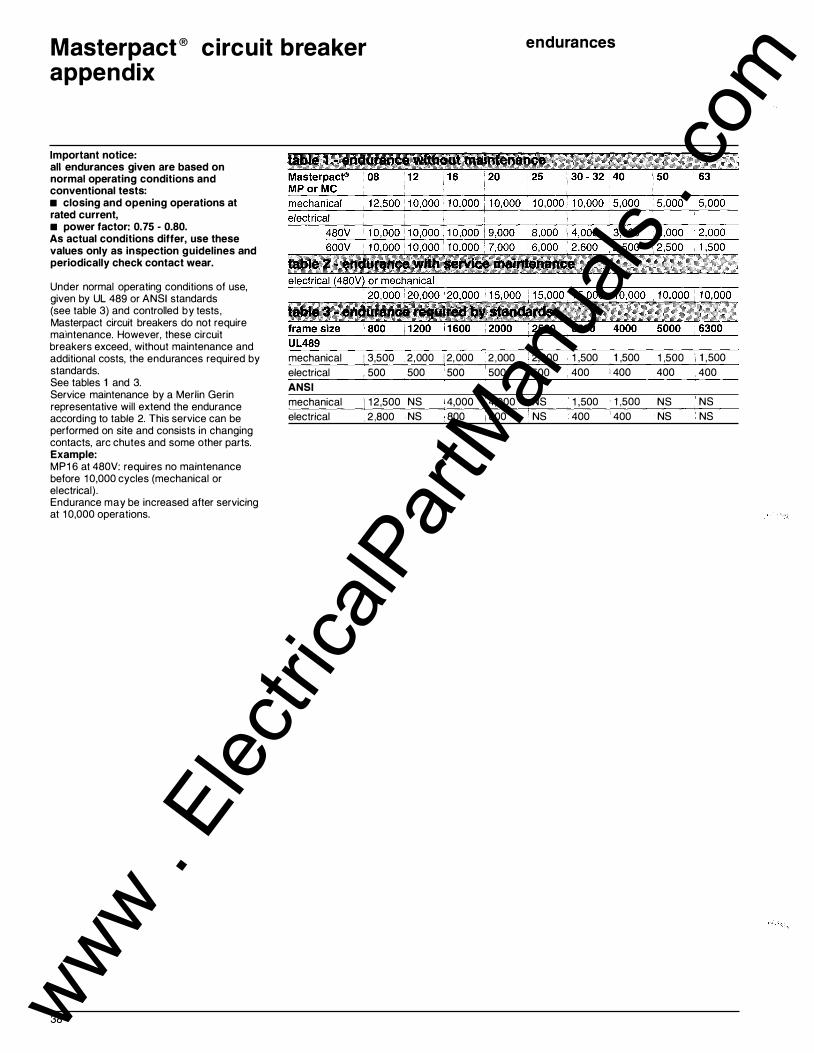
Masterpact ® circuit breaker appendix
Important notice: all endurances given are based on normal operating conditions and conventional tests: • closing and opening operations at rated current, • power factor: 0. 75 - 0.80. As actual conditions differ, use these values only as inspection guidelines and periodically check contact wear.
Under normal operating conditions of use, given by UL 489 or ANSI standards (see table 3) and controlled by tests , Masterpact circuit breakers do not require maintenance. However, these circuit breakers exceed, without maintenance and additional costs, the endurances required by standards. See tables 1 and 3. Service maintenance by a Merlin Gerin representative will extend the endurance according to table 2. This service can be performed on site and consists in changing contacts, arc chutes and some other parts. Example: MP1 6 at 480V: requires no maintenance before 1 0,000 cycles (mechanical or electrical) . Endurance may be increased after servicing at 1 0,000 operations.
38
mechanical : 3,500 electrical . 500 ANSI
mechanical 1 1 2 ,500 electrical 2 ,800
2,000 1 2, 000 500 ' 500
NS 4,000 NS 800
endurances
2 ,000 : 2,000 1 ,500 . 1 ,500 1 ,500 • 1 ,500 500 > 5oo 400 1 400 400 , 400
. 4,000 ; NS 1 ,500 · 1 ,500 NS NS 800 ' NS 400 ' 400 NS NS
www . El
ectric
alPar
tMan
uals
. com

Masterpact ® circuit breaker appendix
molded case circuit breaker In addition to UL 489 and ANSI C37-1 3 Masterpact circuit breakers comply with IEC 947-2 standard as per the table below:
type 3-pole
ampere interrupting ratings rating (A) UL489
A 4-pole version complements the product line. For further information, please contact a sales representative.
IEC 947-2 --------------------------------------------
rms sym. amps ' 480V 600V short
time
MP08 H1 800 : 65kA 65kA 50kA MP12 H1 1 200 MP1 6 H1 1 600 MP20 H1 2000 MP25 H1 2500 M P30 H1 3000 MP40 H1 4000 MP50 H1 5000 MP63 H 1
MP08 H2 800 MP1 2 H2 1 200 MP16 H2 1 600 MP20 H2 2000 M P25 H2 2500 MP30 H2 3000 MP40 H2 4000 M P50 H2 5000
. 65kA 65kA 65kA 65kA 75kA 75kA 75kA 75kA 75kA 75kA 1 00kA 1 00kA
· 1 OOkA 1 OOkA
50kA 50kA 75kA 75kA 75kA 1 00kA 1 00kA
1 OOkA 65kA 50kA I 1 OOkA 75kA 75kA 1 OOkA 75kA 75kA 1 00kA 75kA 75kA
: 1 25kA 1 OOkA 1 OOkA " 1 25kA 1 00kA 1 00kA
MP63 H2 6300 CD 1 50kA 1 00kA 1 00kA CD not U L listed
auxil iary and position switches
DC 48 i S 1. 3 3 '• 3 1 2s i 3 o.s I o.s o.3 250 ' 3 0.25 0.25 : 0. 1 5 500 0.5
440V 690V leu lcs leu lcs
65kA 65kA 65kA 75kA 75kA 75kA 1 00kA 1 00kA 1 00kA
65kA 65kA 65kA 65kA 65kA 65kA 65kA 65kA 65kA 75kA 75kA 75kA 75kA 75kA 75kA 75kA 75kA 75kA 1 OOkA 85kA 85kA 1 00kA 85kA 85kA 1 OOkA 85kA 85kA
1 OOkA 1 OOkA 85kA 85kA 1 OOkA 1 OOkA 85kA 85kA 1 OOkA 1 OOkA 85kA 85kA 1 OOkA 1 OOkA 85kA 85kA 1 OOkA 1 OOkA 85kA 85kA 1 OOkA 1 OOkA 85kA 85kA 1 50kA 1 25kA 85kA 85kA 1 50kA 1 25kA 85kA 85kA 1 50kA 1 25kA 85kA 85kA
3 3 0.3 : 0.5 0. 1 5 ' 0.25
OF: heavy duty 0: standard OFSUP: 24 additional CE: connected CD: disconnected CT: test
international standards
DC 24 DC 24-30 48 48-60 1 25 1 00-1 25
closing coil
UL 489 Listed IEC 947-2 60 Hz 1 20 50/60 Hz
240 1 1 0- 1 27 220-250
DC 24 DC 24 48 48 1 25 1 25 250 250
60 Hz 1 20 50/60 Hz 1 1 0- 1 27 �24
�0�--���---
2�
2�0--2
�5�0
--
480 440-480 DC _24 ______ D_C _______ 2_4 ____ __
48 48 1 25 1 25 250 250
undervoltage trip -�����.,..,....,.
60 Hz 1 20 50/60 Hz 1 1 0- 1 27
DC
----------------------
240 220-250 480 440-480 24 DC 24 48 48 1 25 1 25 250 250
39 www . El
ectric
alPar
tMan
uals
. com

Masterpact® circuit breaker appendix
MP1 008A.O
pickup setting
MP1 008A.O
trip level - - - - - - - - - - - -
trip unit without thermal memory
MP1 008A.O
trip level
STR trip unit with thermal memory
40
purpose The thermal memory function allows an optimization of cables or bus bar protection in case of low amplitude repetitive faults. Such faults can be due to repetitive motor starlings, fluctuating load or subsequent reclosing after a fault.
Traditional electronic protection has no effect when facing such repetitive faults because the duration of each overload above the pickup setting is too short to achieve effective tripping. Nevertheless, each overload involves a temperature rise in the installation, the cumulative effect of which could lead to overheating of the system.
principle The thermal memory function remembers and integrates the thermal heating caused by each pickup setting overrun. Before tripping, the integrated heating value will reduce the associated time delay and therefore, the reaction of the trip unit will be closer to the real heating of the power network system. After tripping, the memory will also reduce the time delay when reclosing the circuit breaker on fault.
STR trip units The STR 38S and STR 58U trip units incorporate the thermal memory as standard: • before tripping on long-time and groundfault protection (if provided) • after tripping on long-time protection only, adjustable min./max. position for the STR 58U trip unit is standard The trip unit measures the internal temperature rise of the circuit breaker by thermal resistors. The cooling time constant of the memory is not fixed, but depends on the over-temperature condition.
thermal memory
MP1 008A.O
temp.
,1\ WARNING
HAZARD OF EQUIPMENT DAMAGE
"min" position must be used only for emergency, when reclosing on fault is absolutely necessary.
Failure to observe this precaution can cause death, severe personal injury or equipment damage.
www . El
ectric
alPar
tMan
uals
. com