mchxxx control handle technical information manual€¦ · the mchxxx single axis control handle...
TRANSCRIPT

Technical Information
MCHXXXControl Handle
powersolutions.danfoss.com

Revision history Table of revisions
Date Changed Rev
February 2017 MCHXXX Potentiometer Models with 1K Ohm table updated 0601
October 2016 Minor updates 0502
August 2016 Updated to Engineering Tomorrow design 0501
September 2013 Rebranded to Danfoss layout FA
January 2011 Various updates EA
May 2010 MCHXXX Potentiometer Models with 1K Ohm table updated DA
February 2010 MCHXXX Potentiometer Models with 1K Ohm table updated CA
August 2009 MCHXXX Potentiometer Models with 1K Ohm table updated BA
January 2009 Corrected operation and storage temperature AB
December 2008 First edition AA
Technical InformationMCHXXX
2 | © Danfoss | February 2017 11022667 | BC00000033en-US0601

OverviewDescription..........................................................................................................................................................................................4Features................................................................................................................................................................................................4
Ordering informationOrdering specification chart.........................................................................................................................................................5
Technical dataSpecifications.....................................................................................................................................................................................8Environmental testing.................................................................................................................................................................... 9
InstallationDimensions.......................................................................................................................................................................................10Connectors....................................................................................................................................................................................... 10Wiring................................................................................................................................................................................................. 11
Connection diagramsPotentiometer option ..................................................................................................................................................................14Potentiometer option with 1K Ohm potentiometer ........................................................................................................14PWM Option (primarily)...............................................................................................................................................................15
PWM option performance.....................................................................................................................................................16
Device repairReturn to............................................................................................................................................................................................17
Technical InformationMCHXXX
Contents
© Danfoss | February 2017 11022667 | BC00000033en-US0601 | 3

Description
The MCHXXX Single Axis Control Handle provides remote electrical actuation of Danfoss pumps/motors,and or other electrically-actuated pump strokers for open loop control systems. The MCHXXX canfunction as a setpoint for analog or microprocessor-controlled systems for controlling position, speed,pressure, horsepower or other dynamic parameters.
Features
• Shock and vibration resistant
• Choice of three mounting styles, with or without watertight case
• Rugged components designed for the construction environment
• High-torque handle actuation gives sure feel
• Simple to install
• Mechanical options include center-lock, spring-return, friction drag, uni/bi-directionality and optionalwire harness with a variety of electrical connectors
• Electrical characteristics customized to the application
Technical InformationMCHXXX
Overview
4 | © Danfoss | February 2017 11022667 | BC00000033en-US0601

Ordering specification chart
A wide range of options to the basic control handle allow custom-tailoring to each application. Thefollowing ordering specification chart is provided for assistance in determining model number. Otheroptions are possible, consult Danfoss with further questions.
Ordering specification chart
MCH X X X X X XXX
Mounting option Control knob type Handle actuation Electricalcharacteristics
Connector Factory assigned
Mounting option
Code Description Detail
1 Base (surface) mount aluminum case Four screws connect to the flanges on the bottom of the metal case.
2 Top mount (drop in) with plastic case Two screws connect to an enlarged mounting plate.Top mounting allows the entire handle to be removed from above the panel.The case is made of black nylon plastic.
3 Top mount (drop in) without case Two screws connect to an enlarged mounting plate.Top mounting allows the entire handle to be removed from above the panel.
4 Panel mount with plastic case Four screws connect to the top plate that holds the boot in place.The case is made of black nylon plastic.
5 Panel mount without case Four screws connect to the top plate that holds the boot in place.
Control knob option
Code Description Detail
1 Non-locking The friction-held handle detents with a springloaded ball to indicate null, whilethe spring-return handle has a spring preload indicating null.The non-lockinghandle has a standard ball knob.
2 Center lock The non-locking handle has a standard ballThe center lock handle has acylindrical knob and provides a positive center lock that unlatches when theoperator pulls up on the knob.
3 Non-locking, auxiliary push button switch This knob is teardrop shaped, with an auxiliary momentary push-button switch ontop.The switch is wired through the handle shaft to the body with three wires(common, normally open, and normally closed).
5 Non-locking, no knob The customer provides customized knob.
6 Three position maintained rocker switch The cylindrical knob has a boot covering the three-position switch in the knob.The switch, wired through the handle, is used for auxiliary functions.
8* Special (no handle or knob)
9 Three position momentary rocker switch This is the same as option 6, but the switch returns to the center position whenreleased.
* Unique configuration, for details contact your Danfoss representative.
Reference Dimensions.
Handle actuation option
Code Description Detail
A Spring return, bi-directional This handle uses a torsion spring to return to the mechanical center position andhas 30 degrees of handle throw on either side of center.
B Friction held, bi-directional This handle has an adjustable drag, set with a clamp-type brake that holds thehandle at the set position and has 30 degrees of handle throw on either side ofthe center detent.
Technical InformationMCHXXX
Ordering information
© Danfoss | February 2017 11022667 | BC00000033en-US0601 | 5

Handle actuation option (continued)
Code Description Detail
C Friction held, uni-directional This handle has 60 degrees of high-resolution of handle throw, rotating on onlyone side of mechanical null, which is at full stroke.It has no detent mechanism.
D Special (friction held, center detent only, no brake)
Electrical characteristics option
Code Description Detail
A Proportional, no switches, 12 VDC This handle’s output curve is fairly linear, with output voltage as a function ofhandle stroke.The supply voltage is 12 Volts, and there are no auxiliary function switches.
B Proportional, center off switch, 12 VDC, This handle has a center-off switch that ensures zero output voltage within ±3degrees of handle center position.
C Proportional, center off switch, 24 VDC Same as option B except this handle runs on a supply voltage of 24 Volts.
D Proportional, center off and auxiliary switch, 12 VDC Same as option B except this handle has a second switch that actuates at +2 or -2degrees.
E Proportional, set-point potentiometer, 12 VDC Same as option B except this handle maintains the same polarity of signal inforward or reverse.
F Step-plus-proportional, 12 VDC This handle uses two switches to give the step-plus-proportional output currenton either side of null.This overcomes deadbands in spool valves (see Specifications on page 8, Step-Plus-Proportional-Control-Handle PWM option illustration).Current beyond this step output is proportional through the rest of the handlethrow.Full current output at 30 degrees handle stroke is maximum of 250 mA.Step current is a maximum of 50% of full current output.
G Step-plus-proportional, 24 VDC Same as option F, except this handle runs on a supply voltage of 24 Vdc.
H Switching This handle is non-proportional. Moving the handle off null activates switchesthat power ON/OFF devices (for example, solenoid valves).
J Step-plus-proportional, full auxiliary switching, 12VDC
This handle uses the step switches for additional secondary functions.Full current output at 30 degrees handle stroke is a maximum of 250 mA.Step current is a maximum of 50% of full current output.
K Proportional, unwired switch The customer uses the unwired center switch to operate an auxiliary function,such as neutral start interlock.
L* Electronic PWM auxiliary switching, 12 Vdc This handle uses a printed circuit board that makes the step height and outputcurrent fully adjustable, accommodating high current applications. It also haspulse width modulation, that dithers the output to overcome hydraulic valvestiction. Full current output at 30 degrees handle stroke is a maximum of 2 Ampsinto a 5 Ohm load. Step current is a maximum 50% of full current output. Typicaldither frequencies (dependent on resistance of the load, specified in the suffixnumber) are: 60 Hz for the HPI solenoid actuator, approximately 400 Hz for theV7058 Hydrotransmission Valve and approximately 1000 Hz for the MCV101A/MCV116A Pressure Control Pilot Valve.
M Proportional, three switches The three switches are: a wired center switch; one unwired switch in forward; andone unwired switch in reverse.
X† Special (no handle or knob)
Y† Special
Z† Special* Option L, Electronic PWM auxiliary switching, 12 Vdc reached its end of life cycle in 2008 and is no longer available.† Unique configuration, for details contact your Danfoss representative.
Technical InformationMCHXXX
Ordering information
6 | © Danfoss | February 2017 11022667 | BC00000033en-US0601

Connector option
Code Description Detail
1 Terminal strip Electrical connections are made to a set of four internal or more screw terminalsdepending on the specific model.
2 Pigtail 1524 mm [60 in] without connector Four wires extend from the handle case.Reference Potentiometer option on page 14 for lengths.
3 Pigtail with unsealed Delphi connector The wires from the case terminate in a Delphi environmental connector.Reference Potentiometer option on page 14.
6 Pigtail with sealed Delphi connector, 4 pin male andfemale
There are two separate connectors, each connects to a separate potentiometer.
7 Pigtail sealed Delphi connector The wires from the case terminate in a sealed Delphi connector.
8 Pigtail sealed DEUTSCH connector The wires from the case terminate in a sealed DEUTSCH connector.
Pigtail (or leadwire) is routed from the control handle to a Delphi environmental connector. Pigtailminimum length is 381 mm [15 in].
For optional connectors, contact your Danfoss representative.
Suffix number
The factory generates these final three numbers. To create the suffix number, supply the followinginformation:• Supply voltage• Number of additional switches needed and actuation angle of each with respect to null• Full current output• Resistance of the driven load• Step current needed (if necessary)
For details regarding unique configurations, contact your Danfoss representative.
Technical InformationMCHXXX
Ordering information
© Danfoss | February 2017 11022667 | BC00000033en-US0601 | 7
Specifications
Electrical
Operating voltage 11 to 15 Vdc (12 Volt models)
22 to 30 Vdc (24 Volt models)
Power*
Load resistance*
Switch current capability 3 Amps inductive at 28 Vdc* Customer specified. Reference Ordering specification chart on page 5.
Mechanical
Handle stroke ± 30º
Spring torque 1.2±.4 N•m [11±4 lbf•in] at center breakaway
2.0±.7 N•m [18±6 lbf•in] at full stroke
Detent torque (over and above friction drag) 1.1 N•m [10 lbf•in]
Friction drag 1.5±.3 N•m [13.5±3 lbf•in]Friction is adjusted at the brake with a 5/32 inch internal hexwrench and 3/8 inch open-end hex wrench.
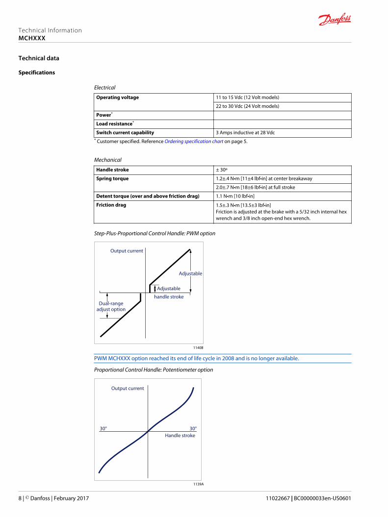
Step-Plus-Proportional Control Handle: PWM option
Output current
Adjustable
Adjustable
handle strokeDual-range
adjust option
1140B
PWM MCHXXX option reached its end of life cycle in 2008 and is no longer available.
Proportional Control Handle: Potentiometer option
30° 30°
Output current
Handle stroke
1139A
Technical InformationMCHXXX
Technical data
8 | © Danfoss | February 2017 11022667 | BC00000033en-US0601

Environmental testing
Temperature
Operating -34º to 66ºC [-30º to 150ºF]
Storage -40º to 77ºC [-40º to 170ºF]
Humidity
After being placed in a controlled atmosphere of 95% humidity at 38ºC [100ºF] for 10 days, the control handle performs normally.
Rain
After being showered from all directions by a high pressure hose, the control handle performs normally (applied to cased models only). This test fulfillsNEMA 4 specifications (IP 65 equivalent).
Vibration
Withstands a vibration test designed for mobile equipment controls consisting of two parts:1. Cycling from 5 to 2000 Hz in each of the 3 axes.2. Resonance dwell for one million cycles for each resonance point in each of the 3 axes.
NEMA (National Electrical Manufacturer Association) NEMA 4 = Intended for indoor or outdoor useprimarily to provide a degree of protection against windblown dust and rain, splashing water, hose-directed water and external ice formation.
Technical InformationMCHXXX
Technical data
© Danfoss | February 2017 11022667 | BC00000033en-US0601 | 9

Dimensions
MCHXXX Control Handle mounting dimensions in mm [in]
149.1 max. [5.87]136.4 ± 0.4 [5.37]
31.75[1.25]
50.8 ± 0.4[2.0]
63.76 max.[2.51]
6.35[0.25]
6.35[0.25] 7.1 (4)
[0.279]
Panel cutout andmounting plate
138.0[5.43] 7.0
[0.275]
33.3[1.31]
66.6[2.62]
124.0 [4.88]150.5 max. [5.93]
85.5 max.[3.37]
4.5 ± 0.008 [2.0]Mounting plate
Mounting plate
50.8[2.0]
50.8[2.0]
25.4[1.0]
25.4[1.0]
54.0[2.12]
Remove burrsfrom both sides of panelto avoid damaging boot
6.2 (4)[0.245]
Customerpanel
Customerpanel
251.5 max.[9.9]
113 max.[4.45]
29.5 [1.16]60.4
[2.38]60.4
[2.38]
121.3 max. [4.78] 121.3 max. [4.78]
Top (drop in)mount
Customerpanel
Tappingscrews
(2)
30º ref. 30º ref. 30º ref. 30º ref. 30º ref. 30º ref. 30º ref. 30º ref.
302.0 max.[11.88]
121.0 max. [4.76] 121.0 max. [4.76]
120.0 max.[4.72]
14.2[0.56]
27.0[1.06]
269.2 max.[10.6]
29.5 max.[1.16]
Surface mount
96.0 max.[3.78]
97.6 max.[3.84]
120.0 max.[4.72]
149.9 max.[5.9]
114.6max.[4.51]
44.4[1.75]
64.1 max.[2.52]
Panel mount Side viewof all
panel mount
Remove collarthat retains boot
and discard
29.5 [1.16]
1135D
Connectors
3 or 4 pin Delphi Connector
Power +
Speed
Ground
Direction
A
B
C
D3524A
4 pin Deutsch Plug DT Series Connector
APower +
CGround
BSpeed
DDirection 3525
Technical InformationMCHXXX
Installation
10 | © Danfoss | February 2017 11022667 | BC00000033en-US0601
For optional connectors, contact your Danfoss representative.
Wiring
A barrier terminal strip inside the handle’s case provides connections to power, ground, andpotentiometers when no external cable is ordered. Run a cable from the strip through the strain reliefprovided on the side or bottom of the case. Reference Potentiometer option on page 14. A clockwisehandle movement causes a current flow from terminal B to A when the terminal strip is facing you.
W Warning
An unforeseen failure may cause an output which could activate a valve or pump. Unexpected vehicle ormechanism movement can endanger people or damage equipment. Handles equipped with a center-offswitch will mitigate this condition. When an active neutral is necessary, provide an operator-presenceinterlock and/or braking system sufficient to stop and hold the system or vehicle.
In most applications, auxiliary switches must be customer-wired, as shown in Potentiometer option onpage 14. When the switch is used as a center-off, power is connected from the external 12 Volt supplyto the terminal labeled common. The switch terminals are 3/16 inch quick-connect. PWM Option(primarily) on page 15 shows a pre-wired control handle with center-off switch and Delphi connector,exhibiting the handle phasing and color coding of the wires.
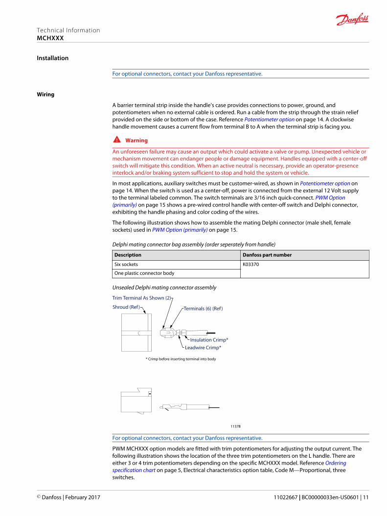
The following illustration shows how to assemble the mating Delphi connector (male shell, femalesockets) used in PWM Option (primarily) on page 15.
Delphi mating connector bag assembly (order seperately from handle)
Description Danfoss part number
Six sockets K03370
One plastic connector body
Unsealed Delphi mating connector assembly
Trim Terminal As Shown (2)
Shroud (Ref ) Terminals (6) (Ref )
Insulation Crimp*Leadwire Crimp*
* Crimp before inserting terminal into body
1137B
For optional connectors, contact your Danfoss representative.
PWM MCHXXX option models are fitted with trim potentiometers for adjusting the output current. Thefollowing illustration shows the location of the three trim potentiometers on the L handle. There areeither 3 or 4 trim potentiometers depending on the specific MCHXXX model. Reference Orderingspecification chart on page 5, Electrical characteristics option table, Code M—Proportional, threeswitches.
Technical InformationMCHXXX
Installation
© Danfoss | February 2017 11022667 | BC00000033en-US0601 | 11

C Caution
Overcurrent could damage the control handle. Use a 1 Amp fuse in series for applications with lowcurrent requirements to avoid damaging the control handle.
MCHXXX PWM option with trim potentiometer configurations
T
F
R
Step Current AdjustForward*Reverse*
* Span adjust or full current output1138B
Handle adjustments
Reverse threshold*
Forward full stroke*
Reverse full stroke*
Forward threshold*
2382
* Clockwise increases output
PWM MCHXXX option reached its end of life cycle in 2008 and is no longer available.
L control handles
Standard L Threshold adjustmentCounter clockwise increases output
Forward full strokeClockwise increases output
Reverse full strokeClockwise increases output
L with (2) threshold adjustments Forward thresholdCounter clockwise increases output
Reverse thresholdClockwise increases output
Forward full strokeClockwise increases output
Reverse full strokeClockwise increases output
Technical InformationMCHXXX
Installation
12 | © Danfoss | February 2017 11022667 | BC00000033en-US0601
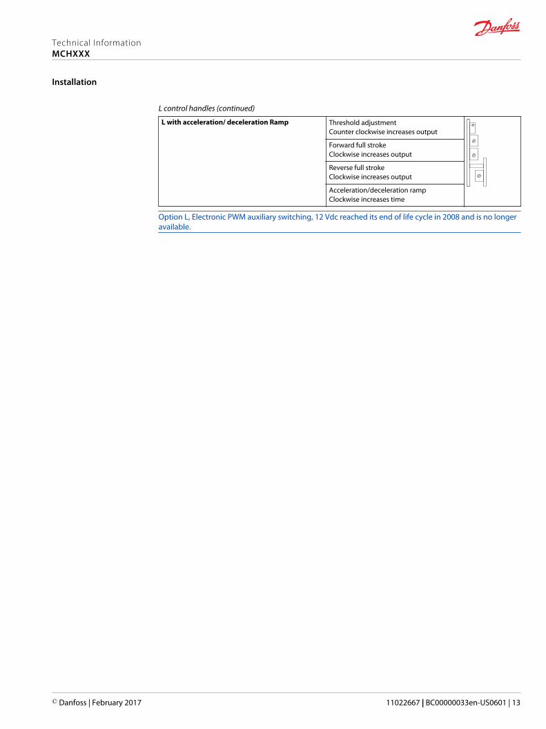
L control handles (continued)
L with acceleration/ deceleration Ramp Threshold adjustmentCounter clockwise increases output
Forward full strokeClockwise increases output
Reverse full strokeClockwise increases output
Acceleration/deceleration rampClockwise increases time
Option L, Electronic PWM auxiliary switching, 12 Vdc reached its end of life cycle in 2008 and is no longeravailable.
Technical InformationMCHXXX
Installation
© Danfoss | February 2017 11022667 | BC00000033en-US0601 | 13
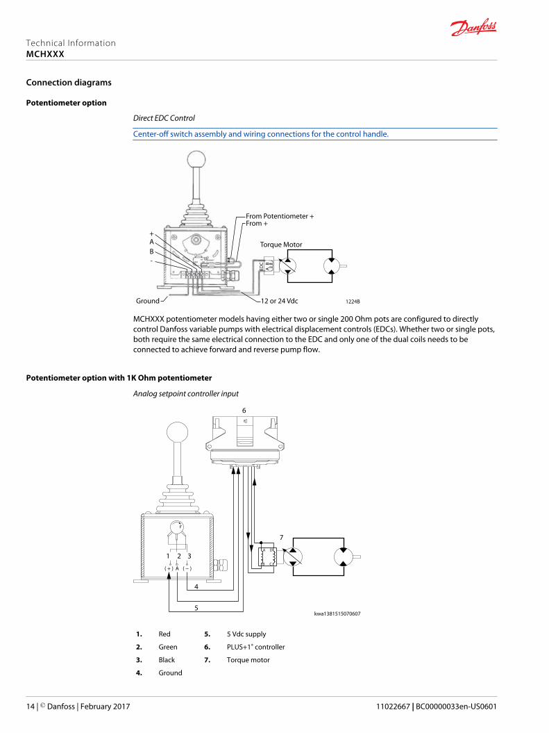
Potentiometer option
Direct EDC Control
Center-off switch assembly and wiring connections for the control handle.
1224B
From Potentiometer +From +
Torque Motor
12 or 24 VdcGround
-BA+
NCCOM NO
EDC
AB
MCHXXX potentiometer models having either two or single 200 Ohm pots are configured to directlycontrol Danfoss variable pumps with electrical displacement controls (EDCs). Whether two or single pots,both require the same electrical connection to the EDC and only one of the dual coils needs to beconnected to achieve forward and reverse pump flow.
Potentiometer option with 1K Ohm potentiometer
Analog setpoint controller input
( + ) (A ) −
A D
B C
6
1 2 3
4
5
7
kwa1381515070607
1. Red 5. 5 Vdc supply
2. Green 6. PLUS+1® controller
3. Black 7. Torque motor
4. Ground
Technical InformationMCHXXX
Connection diagrams
14 | © Danfoss | February 2017 11022667 | BC00000033en-US0601
MCHXXX potentiometer models having a 1K Ohm pot are commonly used as analog input to a controller(for example, SX or PLUS+1® MC200 Controllers). The supply voltage (5 VDC sensor supply) is usuallysupplied from the controller.
MCHXXX potentiometer models typically used for a PLUS+1® input
Materialnumber
Model code Centerlock Springreturn
Frictionhold
5 Vdcsupply
Terminalstrip
Microswitches
Forward Neutral Reverse
11090431 MCH19AM1649Rocker 3-posmomentary
X X X X X X
MCH11CB1510 X X X X
11046484 MCH12AR1642 X X X X X X
10106017 MCH21CB1510 X X X X
11048497 MCH22AA1644 X X X X
11147104 MCH22AB1648 X X X X X
11068164 MCH22BB1648 X X X X X
11181083 MCH41BB1648 X X X X
MCH41BM1504 X X X X X X
MCH41AB1648 X X X X
11068165 MCH42BB1644 X X X X X
MCH51AM1497 X X X X X X
11017769 MCH51BB1535 X X X X
MCH51BD1517 X X X X
MCH52BM1497 X X X X X X
PWM Option (primarily)
PWM MCHXXX option reached its end of life cycle in 2008 and is no longer available.
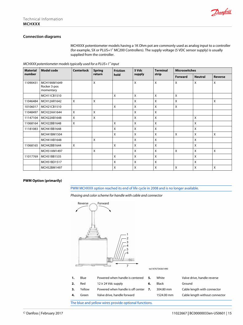
Phasing and color scheme for handle with cable and connector
Reverse Forward
123456
7toi1476734361490
1. Blue Powered when handle is centered 5. White Valve drive, handle reverse
2. Red 12 ir 24 Vdc supply 6. Black Ground
3. Yellow Powered when handle is off center 7. 304.80 mm Cable length with connector
4. Green Valve drive, handle forward 1524.00 mm Cable length without connector
The blue and yellow wires provide optional functions.
Technical InformationMCHXXX
Connection diagrams
© Danfoss | February 2017 11022667 | BC00000033en-US0601 | 15
PWM option performance
Null current ±5 mA maximum if not switched (12 Vdc models)
±8 mA maximum if not switched (24 Vdc models)
Center deadband (optional) ±3º nominal
Full stroke current capability*
Step current Step current occurs at end of deadband.* Customer specified. Reference Ordering Information.
Technical InformationMCHXXX
Connection diagrams
16 | © Danfoss | February 2017 11022667 | BC00000033en-US0601

Return to
Danfoss
Return Goods Department
3500 Annapolis Lane North
Minneapolis, Minnesota 55447
For devices in need of repair or evaluation, include a description of the problem and what work you believe needs to be done, along with your name, address and telephone number.
Technical InformationMCHXXX
Device repair
© Danfoss | February 2017 11022667 | BC00000033en-US0601 | 17

Technical InformationMCHXXX
18 | © Danfoss | February 2017 11022667 | BC00000033en-US0601

Technical InformationMCHXXX
© Danfoss | February 2017 11022667 | BC00000033en-US0601 | 19

Danfoss Power Solutions is a global manufacturer and supplier of high-quality hydraulic andelectronic components. We specialize in providing state-of-the-art technology and solutionsthat excel in the harsh operating conditions of the mobile off-highway market. Building onour extensive applications expertise, we work closely with our customers to ensureexceptional performance for a broad range of off-highway vehicles.
We help OEMs around the world speed up system development, reduce costs and bringvehicles to market faster.
Danfoss – Your Strongest Partner in Mobile Hydraulics.
Go to www.powersolutions.danfoss.com for further product information.
Wherever off-highway vehicles are at work, so is Danfoss. We offer expert worldwide supportfor our customers, ensuring the best possible solutions for outstanding performance. Andwith an extensive network of Global Service Partners, we also provide comprehensive globalservice for all of our components.
Please contact the Danfoss Power Solution representative nearest you.
Local address:
Danfoss Power Solutions GmbH & Co. OHGKrokamp 35D-24539 Neumünster, GermanyPhone: +49 4321 871 0
Danfoss Power Solutions ApSNordborgvej 81DK-6430 Nordborg, DenmarkPhone: +45 7488 2222
Danfoss Power Solutions (US) Company2800 East 13th StreetAmes, IA 50010, USAPhone: +1 515 239 6000
Danfoss Power Solutions Trading(Shanghai) Co., Ltd.Building #22, No. 1000 Jin Hai RdJin Qiao, Pudong New DistrictShanghai, China 201206Phone: +86 21 3418 5200
Danfoss can accept no responsibility for possible errors in catalogues, brochures and other printed material. Danfoss reserves the right to alter its products without notice. This also applies to productsalready on order provided that such alterations can be made without changes being necessary in specifications already agreed.All trademarks in this material are property of the respective companies. Danfoss and the Danfoss logotype are trademarks of Danfoss A/S. All rights reserved.
© Danfoss | February 2017 11022667 | BC00000033en-US0601
Products we offer:
• Bent Axis Motors
• Closed Circuit Axial PistonPumps and Motors
• Displays
• Electrohydraulic PowerSteering
• Electrohydraulics
• Hydraulic Power Steering
• Integrated Systems
• Joysticks and ControlHandles
• Microcontrollers andSoftware
• Open Circuit Axial PistonPumps
• Orbital Motors
• PLUS+1® GUIDE
• Proportional Valves
• Sensors
• Steering
• Transit Mixer Drives
Comatrolwww.comatrol.com
Turolla www.turollaocg.com
Hydro-Gearwww.hydro-gear.com
Daikin-Sauer-Danfosswww.daikin-sauer-danfoss.com