mclane time series sediment trap user manualmclanelabs.com/wp-content/uploads/sediment trap... ·...
TRANSCRIPT
User Manual McLane Time Series Sediment Trap
McLane Time Series Sediment Trap
How to contact us: • E-mail: [email protected] • Fax: 508-495-3333 • Phone: 508-495-4000 • Internet: http://www.mclanelabs.com
Sediment Trap User Manual Revision History:
January 2006 Rev E
December 2004 Rev D
November 2002 Rev C
May 1999 Rev B
January 1992 Rev A
Sediment Trap User Manual Table of Contents
Chapter 1 Introduction.................................................................................................. 1-1 Mark78H-21 and Mark78HW-13 Sediment Trap........................................................ 1-1 Using this Manual ........................................................................................................ 1-1 Sediment Trap Overview ............................................................................................. 1-1
Integrating the Optional Compass/Tilt Sensor......................................................... 1-2 Sediment Trap Line Drawing................................................................................... 1-2 Sediment Trap Components..................................................................................... 1-3 Sediment Trap Specifications .................................................................................. 1-5 Specifications that Differ by Trap Model ................................................................ 1-6
Sediment Trap Toolkit ................................................................................................. 1-7 Contacting McLane Research Laboratories................................................................. 1-8
Chapter 2 Mechanical Description............................................................................... 2-1 Frame ........................................................................................................................... 2-2 Controller Housing....................................................................................................... 2-2
End Cap Bulkhead Connectors, Plastic Inserts and Bolts........................................ 2-3 Funnel .......................................................................................................................... 2-5 Rotator Assembly......................................................................................................... 2-7
Gear Plate Assembly................................................................................................ 2-8 Plastic Ball Bearings ................................................................................................ 2-8 Variseals®................................................................................................................. 2-9
Drive Motor ............................................................................................................... 2-10 Serial Number ............................................................................................................ 2-11
Chapter 3 Electronic Description................................................................................. 3-1 Controller Electronics Stack ........................................................................................ 3-1
TT8V2 Microcontroller Board................................................................................. 3-2 AUX Stepper Motor Circuit Board.......................................................................... 3-3
Battery Connection/Powering on the Trap .................................................................. 3-3
Chapter 4 Maintenance and Storage............................................................................ 4-1 Cleaning and Inspecting the Controller Housing......................................................... 4-2
O-Rings .................................................................................................................... 4-2 Inspecting the Drive Motor Assembly......................................................................... 4-2
Adding Oil to the Drive Motor ................................................................................ 4-4 Aligning the Fixed and Gear Plates and Reattaching the Drive Motor ................... 4-6
Replacing Batteries ...................................................................................................... 4-7 Battery Installation................................................................................................... 4-7 Backup Battery....................................................................................................... 4-10
Storing the Sediment Trap ......................................................................................... 4-10
TOC-1
Chapter 5 Operations .................................................................................................... 5-1 Preparing and Attaching Sample Bottles ..................................................................... 5-1 Instrument Current Consumption ................................................................................ 5-2
Battery Duration Example Calculation.................................................................... 5-2
Chapter 6 Launch and Recovery.................................................................................. 6-1 Attaching to a Mooring................................................................................................ 6-1 Recovery Procedure ..................................................................................................... 6-2
Removing the Sample Bottles.................................................................................. 6-2
Chapter 7 Sediment Trap User Interface .................................................................... 7-1 Power-Up Sequence..................................................................................................... 7-1 Main Menu – Operating the Sediment Trap ................................................................ 7-1 <1> Set Time ............................................................................................................... 7-2 <2> Diagnostics ........................................................................................................... 7-3
Low Battery Messages............................................................................................. 7-3 <3> Fill Bottles ............................................................................................................ 7-4 <4> Sleep ..................................................................................................................... 7-4 <5> Create Schedule.................................................................................................... 7-5
Sampling Schedule Options..................................................................................... 7-5 <1> Enter each event time ....................................................................................... 7-5 <2> Enter start date & interval ................................................................................ 7-5 <3> Enter start date & end date ............................................................................... 7-6
<6> Deploy System ..................................................................................................... 7-6 <7> Offload Data ......................................................................................................... 7-7
Display Backup EEPROM....................................................................................... 7-7 Contacting McLane...................................................................................................... 7-9 Programming for Deployment ................................................................................... 7-10
Chapter 8 Data Offload and Processing ...................................................................... 8-1 Recovering the Data File ............................................................................................. 8-1
Appendix A Operating Crosscut and Crosscut for Windows................................... A-1 Using Crosscut ............................................................................................................ A-1
First Time Crosscut Use.......................................................................................... A-1 Editing the Registry to Enable Crosscut ................................................................. A-2 Capturing Data Files Using Crosscut...................................................................... A-2
Using Crosscut for Win .............................................................................................. A-3 First-Time Crosscut for Win Use............................................................................ A-4 Capturing Data Files with Crosscut for Win........................................................... A-4
Connecting the Sediment Trap to a PC....................................................................... A-5 Additional Documentation.......................................................................................... A-5
TOC-2
Appendix B Optional Compass/Tilt Sensor.................................................................B-1 Compass/Tilt Sensor Firmware Options......................................................................B-2
Diagnostics Display with Compass/Tilt Sensor.......................................................B-2 Setting Tilt Data Frequency .....................................................................................B-3 Offloading Data with the Compass/Tilt Installed ....................................................B-3
Calibrating the Compass ..............................................................................................B-5 Tilt Data and Alignment ..............................................................................................B-5
Tilt Alignment..........................................................................................................B-6 Degaussing the Batteries..............................................................................................B-8 Battery Duration when using Compass/Tilt Sensor.....................................................B-9
Appendix C Rotator Assembly Variseals® and Bearings.......................................... C-1 Overview......................................................................................................................C-1 Step 1 − Remove Components From the Frame..........................................................C-2 Step 2 − Clean and Replace Variseals® .......................................................................C-5 Step 3 − Clean and Replace Ball Bearings ..................................................................C-7 Step 4 − Reassemble Rotator Assembly ......................................................................C-8 Step 5 − Perform a Leak Test ......................................................................................C-9 Step 6 − Reinstall Components onto the Frame.........................................................C-10
Appendix D PARFLUX Wet Sample Particle Divider (WSD-10)............................ D-1 Setting Up the Wet Sample Divider............................................................................ D-2 Using the Wet Sample Divider ................................................................................... D-3 WSD-10 Specifications............................................................................................... D-4
Appendix E PARFLUX Mark 8 Sediment Trap.........................................................E-1 Mark 8 Sediment Trap Specifications..........................................................................E-2
TOC-3

TOC-4

Sediment Trap User Manual List of Figures
Figure 1-1: Sediment Trap Line Drawing.................................................................... 1-2 Figure 1-2: Sediment Trap Toolkit .............................................................................. 1-7 Figure 2-1: Sediment Trap Full View......................................................................... 2-1 Figure 2-2: Controller Housing End Cap Bulkhead Connectors ................................ 2-3 Figure 2-3: Aligning Cable Connector with Thumb Bump........................................ 2-4 Figure 2-4: Funnel and Sample Bottle Side View ...................................................... 2-5 Figure 2-5: Honeycomb Baffle ................................................................................... 2-6 Figure 2-6: Rotator Assembly with Sample Bottles Installed .................................... 2-7 Figure 2-7: Gear Ring Alignment Hole and Sample Bottle Hole #1.......................... 2-8 Figure 2-8: Bottom Fixed Plate and Gear Ring .......................................................... 2-8 Figure 2-9: Plastic Ball Bearings ................................................................................. 2-8 Figure 2-10: Gear Ring with Variseals® ..................................................................... 2-9 Figure 2-11: Variseal® Installation .............................................................................. 2-9 Figure 2-12: Drive Motor Housing ........................................................................... 2-10 Figure 2-13: Serial Number Label ............................................................................. 2-11 Figure 3-1: Sediment Trap Controller Stack................................................................ 3-1 Figure 3-2: Microcontroller and Stepper Motor Boards ............................................. 3-2 Figure 3-3: Sediment Trap Main Battery Pack ........................................................... 3-3 Figure 3-4: Connecting the Battery ............................................................................ 3-4 Figure 4-1: Controller and Drive Motor Housings ...................................................... 4-1 Figure 4-2: More Silicone Oil Needed......................................................................... 4-3 Figure 4-3: Correct Silicone Oil Level ........................................................................ 4-3 Figure 4-4: Adding Silicone Oil .................................................................................. 4-4 Figure 4-5: Back Off Fill Hole Screw and Press Up on Bladder................................. 4-5 Figure 4-6: Oil Around Fill Hole Screw...................................................................... 4-5 Figure 4-7: Cleaning Excess Oil from Fill Plug .......................................................... 4-6 Figure 4-8: Battery End Cap ........................................................................................ 4-8 Figure 4-9: Empty Battery Holder (End Cap Removed) ............................................. 4-8 Figure 4-10: Correct Battery Direction....................................................................... 4-9 Figure 4-11: Battery End Cap ..................................................................................... 4-9 Figure 6-1: Sediment Trap Mooring Array.................................................................. 6-1 Figure 7-1: Set Time display........................................................................................ 7-1 Figure 7-2: Main Menu display ................................................................................... 7-2 Figure 7-3: Diagnostics display ................................................................................... 7-3 Figure 7-4: Low Battery Voltage display .................................................................... 7-3 Figure 7-5: Critically Low Battery Voltage display .................................................... 7-4 Figure 7-6: Critically Low Battery Voltage – Offload Data display ........................... 7-4 Figure 7-7: Fill Bottles display .................................................................................... 7-4
LOF-1
Figure 7-8: Schedule Menu display ............................................................................ 7-5 Figure 7-9: Enter Start Date and End Date display..................................................... 7-6 Figure 7-10: Display Backup EEPROM display ........................................................ 7-8 Figure 7-11: McLane Contact Information display .................................................... 7-9 Figure 7-12: Previous Deployment Records will be Erased display ......................... 7-10 Figure 7-13: Enter Number of Events to Program display ........................................ 7-11 Figure 7-14: Schedule Menu display ........................................................................ 7-11 Figure 7-15: Enter Start Date and Time display ....................................................... 7-11 Figure 7-16: Deploy System display......................................................................... 7-12 Figure 7-17: Modify an Event display ...................................................................... 7-12 Figure 7-18: Change Time & Date display............................................................... 7-13 Figure 7-19: Header Information display ................................................................. 7-13 Figure 7-20: Header Information display ................................................................. 7-14 Figure 8-1: Offload/Display All Data File display ..................................................... 8-2 Figure B-1: Compass/Tilt Sensor Board.....................................................................B-1 Figure B-2: Diagnostics with Compass/Tilt Sensor display .......................................B-2 Figure B-3: Tilt Sample Interval display ....................................................................B-3 Figure B-4: EEPROM Including Compass and Tilt display.......................................B-4 Figure B-5: Correct End Cap Orientation in Controller Housing...............................B-6 Figure B-6: Incorrect End Cap Orientation in Controller Housing ............................B-6 Figure B-7: Check for Level Trap ..............................................................................B-7 Figure B-8: Secure U-Bolts Around the Controller Housing .....................................B-8 Figure C-1: Remove Drive Motor from Top Fixed Plate ............................................C-2 Figure C-2: Remove Controller Housing from the Cross Channel..............................C-3 Figure C-3: Remove Cross Channel From Frame .......................................................C-3 Figure C-4: Gear Plate Assembly Under the Top Fixed Plate.....................................C-4 Figure C-5: Variseals® in Gear Ring Grooves.............................................................C-5 Figure C-6: Installing Variseal® Thin Side Down ......................................................C-6 Figure C-7: Removing Bottom Fixed Plate ................................................................C-7 Figure C-8: Fill Plug on Rotator Assembly ................................................................C-9 Figure C-9: Performing Leak Test............................................................................C-10 Figure D-1: WSD-10 Wet Sample Divider................................................................ D-1 Figure D-2: WSD Rotary Head Controls................................................................... D-1 Figure D-3: WSD-10 Tower Controls ....................................................................... D-1 Figure D-4: Installing Sample Tray Back.................................................................. D-2 Figure D-5: Installing Sample Tray Front ................................................................. D-3 Figure E-1: Mark 78H and Mark 8 Traps ...................................................................E-1
LOF-2
Chapter 1 Introduction
Mark78H-21 and Mark78HW-13 Sediment Trap This manual describes the operation and maintenance of the PARFLUX Mark 78H
Sediment Trap, a time-series instrument that uses 21 or 13 cup sample bottles to collect settling
particles in situ and measure sample export flux and seasonal variability. Before a deployment,
the following must be completed:
• Connect the battery
• Fill, attach and align the sample bottles
• Program the deployment
• Attach the Trap to the mooring
NOTE
The descriptions and photographs in this User Manual feature Mark78H 21 and 13 cup
Sediment Traps. Refer to Appendix E in this User Manual for information about the Mark 8, a
smaller 13 cup Trap that uses the same mechancial components as the Mark78H.
Using this Manual First-time operators should read this Chapter and chapters 2 through 5 in this User
Manual to learn about Sediment Trap operation and maintenance. Chapter 2, “Mechanical
Description” and Chapter 3, “Electronic Description” detail the Sediment Trap mechanical and
electrical components. Chapter 4, “Maintenance and Storage” describes cleaning, maintaining,
and storing the Sediment Trap. Chapter 5, “Operations” and Chapter 6, “Launch and Recovery”
describe pre-deployment, launch and recovery procedures. Chapter 7, “Sediment Trap User
Interface” and Chapter 8, “Data Offload and Processing” explain programming the Sediment
Trap for deployment and recovering data. Appendices in this User Manual describe using
Crosscut to create permanent log files and using the optional Tilt/Compass sensor to gather
additional deployment data.
Sediment Trap Overview The Mark 78H Sediment Trap is a time-series instrument that collects settling particles.
Collection options are a 21 cup trap that holds 250 ml or 500 ml in each sample bottle or a 13 cup
trap with larger, wider sample bottles that hold 250 ml or 500 ml each. The Trap can be deployed
1-1
to depths up to 10,000 meters with a stand-alone mooring or as a large high-tension vertical array.
Deployment duration can be short, such as days and weeks, or as long as 18 months.
The Trap firmware records operational conditions during the deployment including the
sample collection date/time, an electronics self-diagnostic report before and after each sampling
event, battery voltage and temperature information.
Integrating the Optional Compass/Tilt Sensor An optional Compass/Tilt sensor can be installed on the Sediment Trap to record a time
history of tilt magnitude and direction. Other sensors, such as transmissometers, scatterometers,
and high accuracy pressure transducers can also interface with the Sediment Trap as either
passive data sources, or active event triggers.
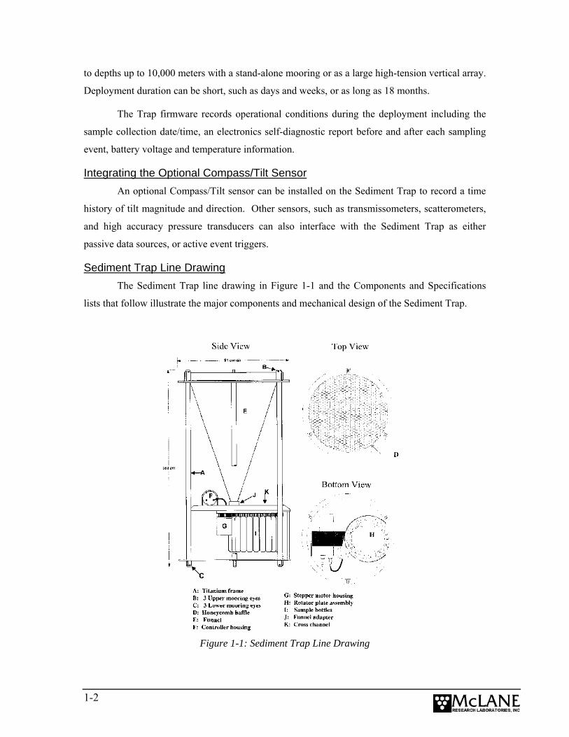
Sediment Trap Line Drawing The Sediment Trap line drawing in Figure 1-1 and the Components and Specifications
lists that follow illustrate the major components and mechanical design of the Sediment Trap.
Figure 1-1: Sediment Trap Line Drawing
1-2
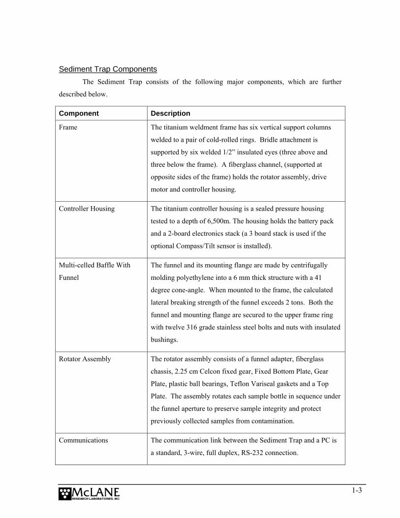
Sediment Trap Components
The Sediment Trap consists of the following major components, which are further
described below.
Component Description
Frame The titanium weldment frame has six vertical support columns
welded to a pair of cold-rolled rings. Bridle attachment is
supported by six welded 1/2” insulated eyes (three above and
three below the frame). A fiberglass channel, (supported at
opposite sides of the frame) holds the rotator assembly, drive
motor and controller housing.
Controller Housing The titanium controller housing is a sealed pressure housing
tested to a depth of 6,500m. The housing holds the battery pack
and a 2-board electronics stack (a 3 board stack is used if the
optional Compass/Tilt sensor is installed).
Multi-celled Baffle With
Funnel
The funnel and its mounting flange are made by centrifugally
molding polyethylene into a 6 mm thick structure with a 41
degree cone-angle. When mounted to the frame, the calculated
lateral breaking strength of the funnel exceeds 2 tons. Both the
funnel and mounting flange are secured to the upper frame ring
with twelve 316 grade stainless steel bolts and nuts with insulated
bushings.
Rotator Assembly The rotator assembly consists of a funnel adapter, fiberglass
chassis, 2.25 cm Celcon fixed gear, Fixed Bottom Plate, Gear
Plate, plastic ball bearings, Teflon Variseal gaskets and a Top
Plate. The assembly rotates each sample bottle in sequence under
the funnel aperture to preserve sample integrity and protect
previously collected samples from contamination.
Communications The communication link between the Sediment Trap and a PC is
a standard, 3-wire, full duplex, RS-232 connection.
1-3
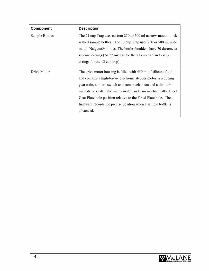
Component Description
Sample Bottles The 21 cup Trap uses custom 250 or 500 ml narrow-mouth, thick-
walled sample bottles. The 13 cup Trap uses 250 or 500 ml wide
mouth Nalgene® bottles. The bottle shoulders have 70 durometer
silicone o-rings (2-027 o-rings for the 21 cup trap and 2-132
o-rings for the 13 cup trap).
Drive Motor The drive motor housing is filled with 450 ml of silicone fluid
and contains a high-torque electronic stepper motor, a reducing
gear train, a micro switch and cam mechanism and a titanium
main drive shaft. The micro switch and cam mechanically detect
Gear Plate hole position relative to the Fixed Plate hole. The
firmware records the precise position when a sample bottle is
advanced.
1-4
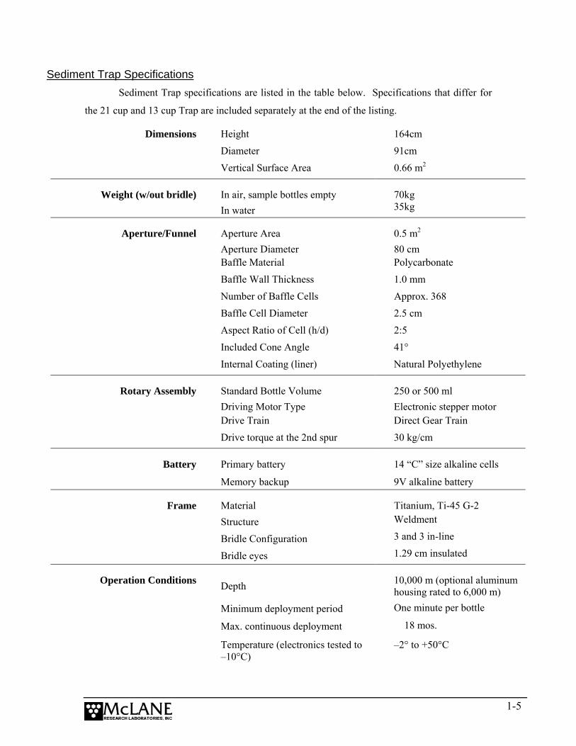
Sediment Trap Specifications Sediment Trap specifications are listed in the table below. Specifications that differ for
the 21 cup and 13 cup Trap are included separately at the end of the listing.
Dimensions Height 164cm Diameter 91cm
Vertical Surface Area 0.66 m2
Weight (w/out bridle) In air, sample bottles empty 70kg In water 35kg
Aperture/Funnel Aperture Area 0.5 m2 Aperture Diameter 80 cm Baffle Material Polycarbonate
Baffle Wall Thickness 1.0 mm
Number of Baffle Cells Approx. 368
Baffle Cell Diameter 2.5 cm
Aspect Ratio of Cell (h/d) 2:5
Included Cone Angle 41°
Internal Coating (liner) Natural Polyethylene
Rotary Assembly Standard Bottle Volume 250 or 500 ml Driving Motor Type Electronic stepper motor Drive Train Direct Gear Train
Drive torque at the 2nd spur 30 kg/cm
Battery Primary battery 14 “C” size alkaline cells
Memory backup 9V alkaline battery
Frame Material Titanium, Ti-45 G-2 Structure Weldment
Bridle Configuration 3 and 3 in-line
Bridle eyes 1.29 cm insulated
Operation Conditions Depth 10,000 m (optional aluminum housing rated to 6,000 m)
Minimum deployment period One minute per bottle
Max. continuous deployment 18 mos.
Temperature (electronics tested to –10°C)
–2° to +50°C
1-5
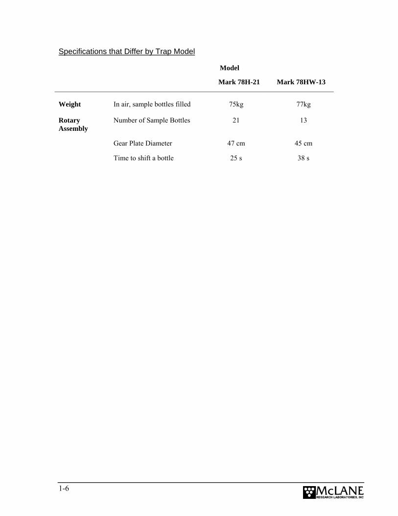
Specifications that Differ by Trap Model
Model
Mark 78H-21 Mark 78HW-13
Weight In air, sample bottles filled 75kg 77kg
Rotary Assembly
Number of Sample Bottles 21 13
Gear Plate Diameter 47 cm 45 cm
Time to shift a bottle 25 s 38 s
1-6
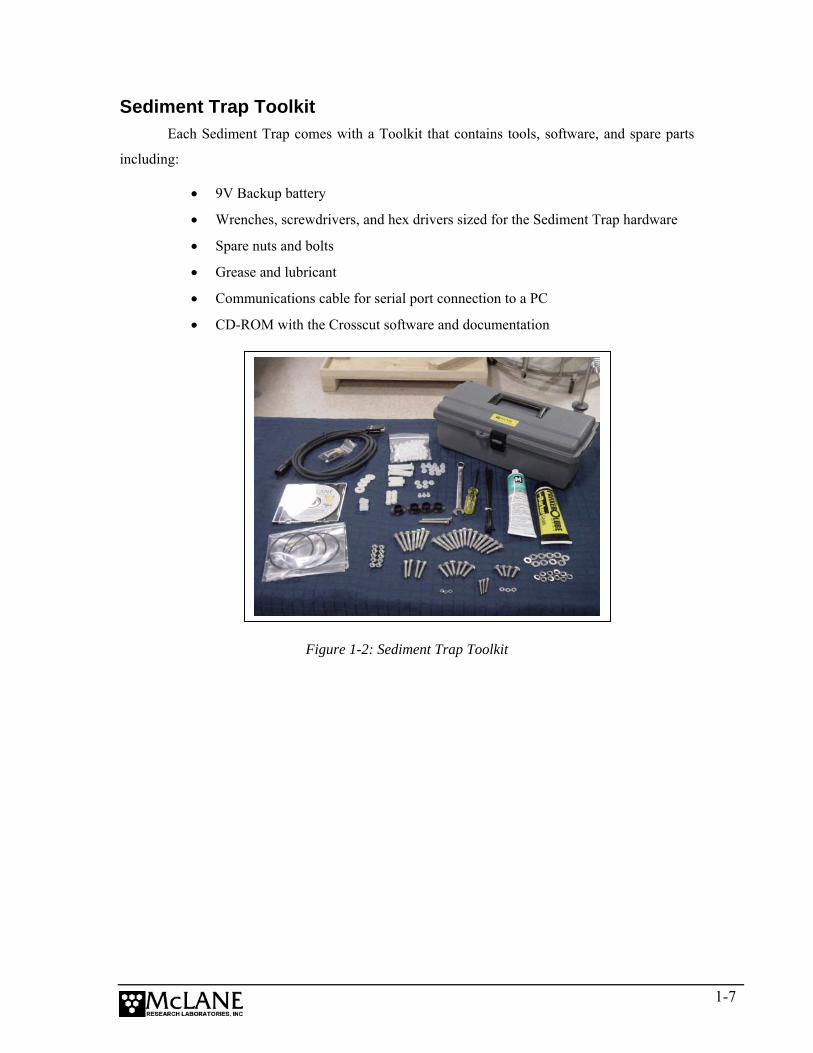
Sediment Trap Toolkit Each Sediment Trap comes with a Toolkit that contains tools, software, and spare parts
including:
• 9V Backup battery
• Wrenches, screwdrivers, and hex drivers sized for the Sediment Trap hardware
• Spare nuts and bolts
• Grease and lubricant
• Communications cable for serial port connection to a PC
• CD-ROM with the Crosscut software and documentation
Figure 1-2: Sediment Trap Toolkit
1-7

Contacting McLane Research Laboratories McLane Research Laboratories can be accessed via the Web at www.mclanelabs.com or
reached by email at [email protected]. The Sediment Trap user interface software also
displays McLane contact information.
Engineers are available by phone at +1 508 495-4000 from 1300 to 2200 (GMT), 0800 to
1700 (Eastern Standard Time). McLane Research Laboratories, Inc. Falmouth Technology Park 121 Bernard E. Saint Jean Drive East Falmouth, MA 02536, USA Tel: (508) 495-4000 Fax: (508) 495-3333 Email: [email protected] WWW: http://www.mclanelabs.com Software version: pst-21_0.c Compiled: Jun 01 2004 20:25:22 Electronics S/N: S/N ML00000-00 Press any key to continue
1-8

Chapter 2 Mechanical Description
This chapter describes each of the following Sediment Trap components in detail:
• Frame
• Controller Housing
• Funnel
• Rotator Assembly
• Drive Motor
Information about the serial number is also included in this Chapter.
Figure 2-1: Sediment Trap Full View
Mooring Eye
Rotator Assembly
Fill PlugController Housing
Drive Motor
Sample Bottles
2-1
Frame The titanium weldment frame protects the samples and mechanical components of the Sediment
Trap with six vertical support columns welded to a pair of cold-rolled rings. An epoxy fiberglass channel
(supported by two pieces of straight angle) holds the rotator assembly, controller housing, and drive
motor. The drive motor housing is mounted directly on the rotator assembly Top Plate by three stainless
steel bolts and nylon spacers. Six welded 1/2” insulated eyes (three above and three below the frame) are
used as bridle attachment points. Insulating bushings are inserted at the attaching points where the bridles
shackle onto the frame.
Controller Housing The titanium controller housing is pressure resistant to depths of 6,500 m. The chamber is
mounted on the frame chassis and secured by two latex rubber-insulated, 316 stainless steel
u-bolts. The top end cap connects to the electronics and batteries.
NOTE
Use only 316 stainless steel hardware on the controller housing. The controller housing titanium
exterior provides corrosion resistance, making it unecessary to install zinc anodes on the end
cap.
2-2
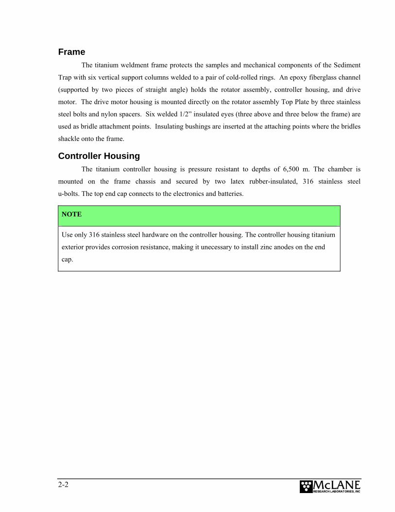
End Cap Bulkhead Connectors, Plastic Inserts and Bolts Three bolt/washer assemblies hold the controller housing end cap in place. A white plastic insert
fits into the screw hole followed by a flat washer, a spring (lock) washer, and lastly the bolt. The
hardware is 316 stainless steel.
Figure 2-2: Controller Housing End Cap Bulkhead Connectors
NOTE
A 9/64” Allen driver is included in the Toolkit. Tighten the end cap bolts only until the lock
washers are flat (20-25 in/lbs). Do not overtighten.
2-3
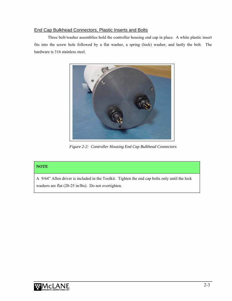
When properly oriented, the “thumb bump” on the cable connector is aligned with the large pin
on the bulkhead connector.
Figure 2-3: Aligning Cable Connector with Thumb Bump
Thumb Bump
Large Pin
IMPORTANT
Boot the PC and start Crosscut before connecting the COM cable to the PC.
2-4
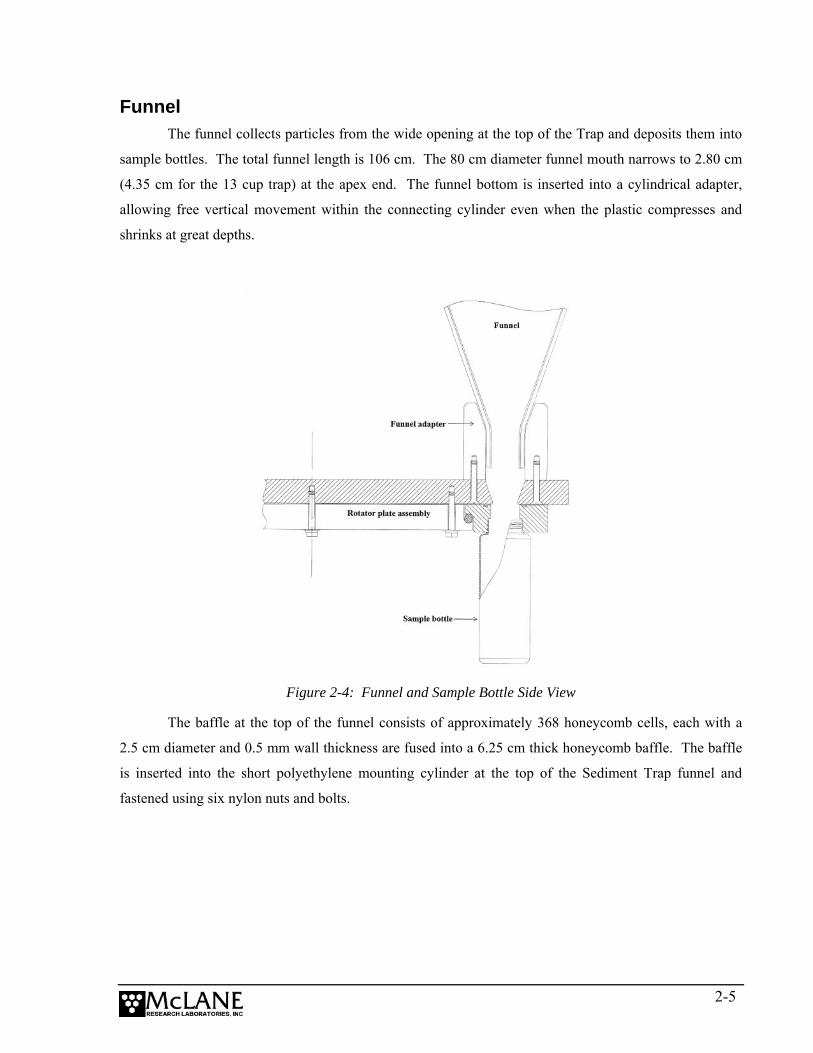
Funnel The funnel collects particles from the wide opening at the top of the Trap and deposits them into
sample bottles. The total funnel length is 106 cm. The 80 cm diameter funnel mouth narrows to 2.80 cm
(4.35 cm for the 13 cup trap) at the apex end. The funnel bottom is inserted into a cylindrical adapter,
allowing free vertical movement within the connecting cylinder even when the plastic compresses and
shrinks at great depths.
Figure 2-4: Funnel and Sample Bottle Side View
The baffle at the top of the funnel consists of approximately 368 honeycomb cells, each with a
2.5 cm diameter and 0.5 mm wall thickness are fused into a 6.25 cm thick honeycomb baffle. The baffle
is inserted into the short polyethylene mounting cylinder at the top of the Sediment Trap funnel and
fastened using six nylon nuts and bolts.
2-5
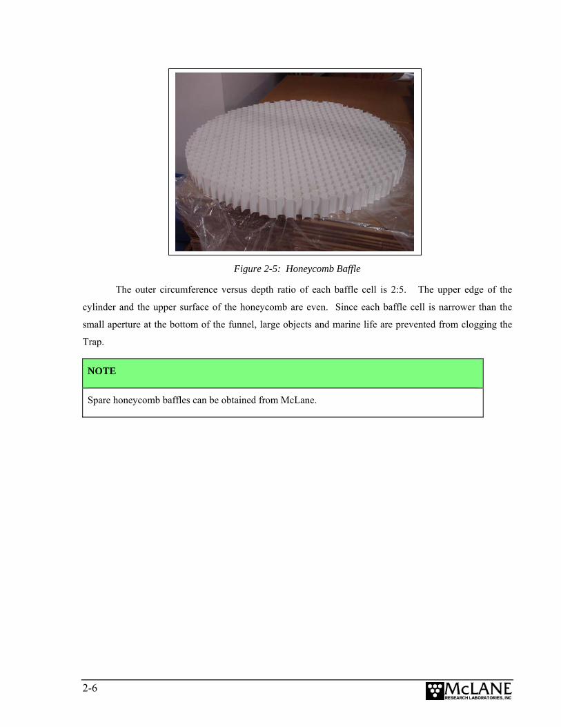
Figure 2-5: Honeycomb Baffle
The outer circumference versus depth ratio of each baffle cell is 2:5. The upper edge of the
cylinder and the upper surface of the honeycomb are even. Since each baffle cell is narrower than the
small aperture at the bottom of the funnel, large objects and marine life are prevented from clogging the
Trap.
NOTE
Spare honeycomb baffles can be obtained from McLane.
2-6
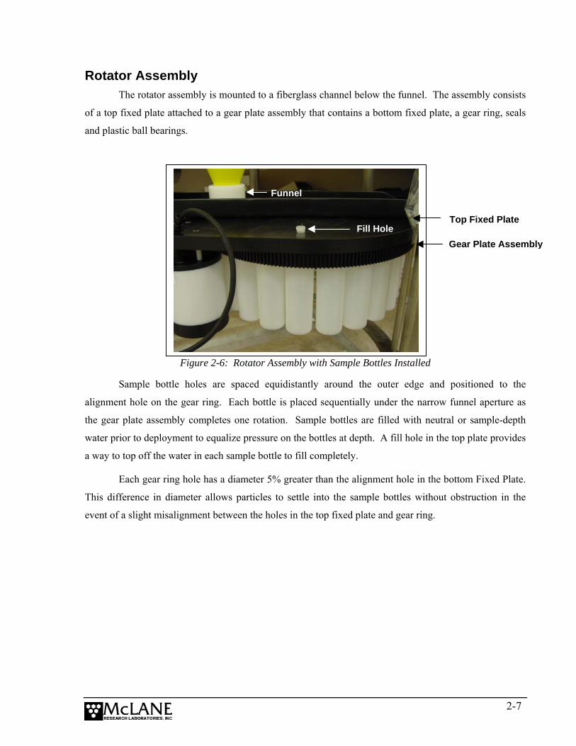
Rotator Assembly The rotator assembly is mounted to a fiberglass channel below the funnel. The assembly consists
of a top fixed plate attached to a gear plate assembly that contains a bottom fixed plate, a gear ring, seals
and plastic ball bearings.
Figure 2-6: Rotator Assembly with Sample Bottles Installed
Funnel
Fill Hole Top Fixed Plate
Gear Plate Assembly
Sample bottle holes are spaced equidistantly around the outer edge and positioned to the
alignment hole on the gear ring. Each bottle is placed sequentially under the narrow funnel aperture as
the gear plate assembly completes one rotation. Sample bottles are filled with neutral or sample-depth
water prior to deployment to equalize pressure on the bottles at depth. A fill hole in the top plate provides
a way to top off the water in each sample bottle to fill completely.
Each gear ring hole has a diameter 5% greater than the alignment hole in the bottom Fixed Plate.
This difference in diameter allows particles to settle into the sample bottles without obstruction in the
event of a slight misalignment between the holes in the top fixed plate and gear ring.
2-7
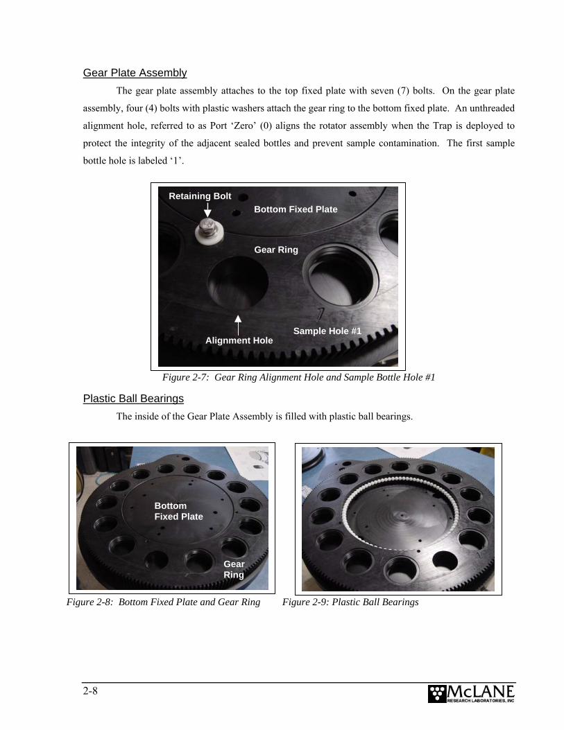
Gear Plate Assembly The gear plate assembly attaches to the top fixed plate with seven (7) bolts. On the gear plate
assembly, four (4) bolts with plastic washers attach the gear ring to the bottom fixed plate. An unthreaded
alignment hole, referred to as Port ‘Zero’ (0) aligns the rotator assembly when the Trap is deployed to
protect the integrity of the adjacent sealed bottles and prevent sample contamination. The first sample
bottle hole is labeled ‘1’.
Figure 2-7: Gear Ring Alignment Hole and Sample Bottle Hole #1
Retaining Bolt
Sample Hole #1
Bottom Fixed Plate
Alignment Hole
Gear Ring
Plastic Ball Bearings The inside of the Gear Plate Assembly is filled with plastic ball bearings.
Figure 2-8: Bottom Fixed Plate and Gear Ring Figure 2-9: Plastic Ball Bearings
Gear Ring
Bottom Fixed Plate
2-8
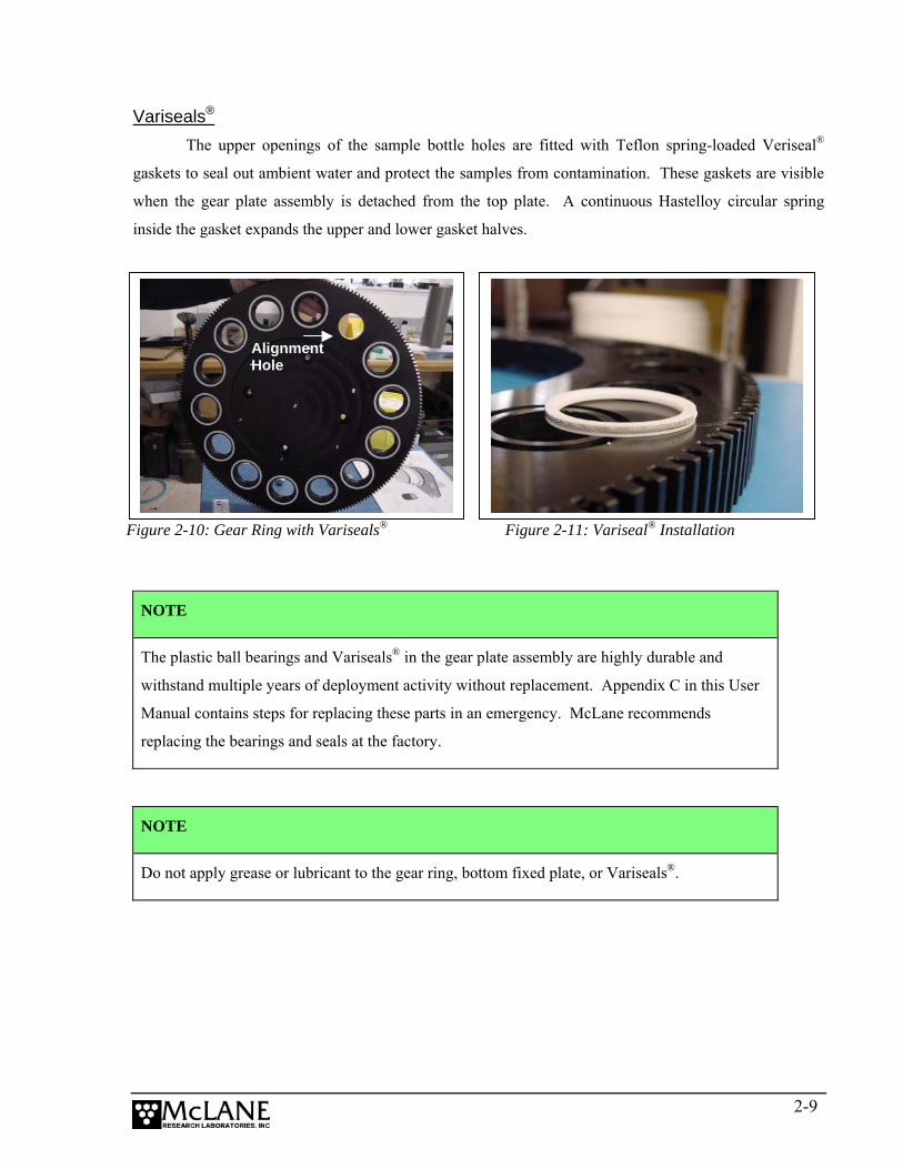
Variseals® The upper openings of the sample bottle holes are fitted with Teflon spring-loaded Veriseal®
gaskets to seal out ambient water and protect the samples from contamination. These gaskets are visible
when the gear plate assembly is detached from the top plate. A continuous Hastelloy circular spring
inside the gasket expands the upper and lower gasket halves.
Figure 2-10: Gear Ring with Variseals® Figure 2-11: Variseal® Installation
Alignment Hole
NOTE
The plastic ball bearings and Variseals® in the gear plate assembly are highly durable and
withstand multiple years of deployment activity without replacement. Appendix C in this User
Manual contains steps for replacing these parts in an emergency. McLane recommends
replacing the bearings and seals at the factory.
NOTE
Do not apply grease or lubricant to the gear ring, bottom fixed plate, or Variseals®.
2-9
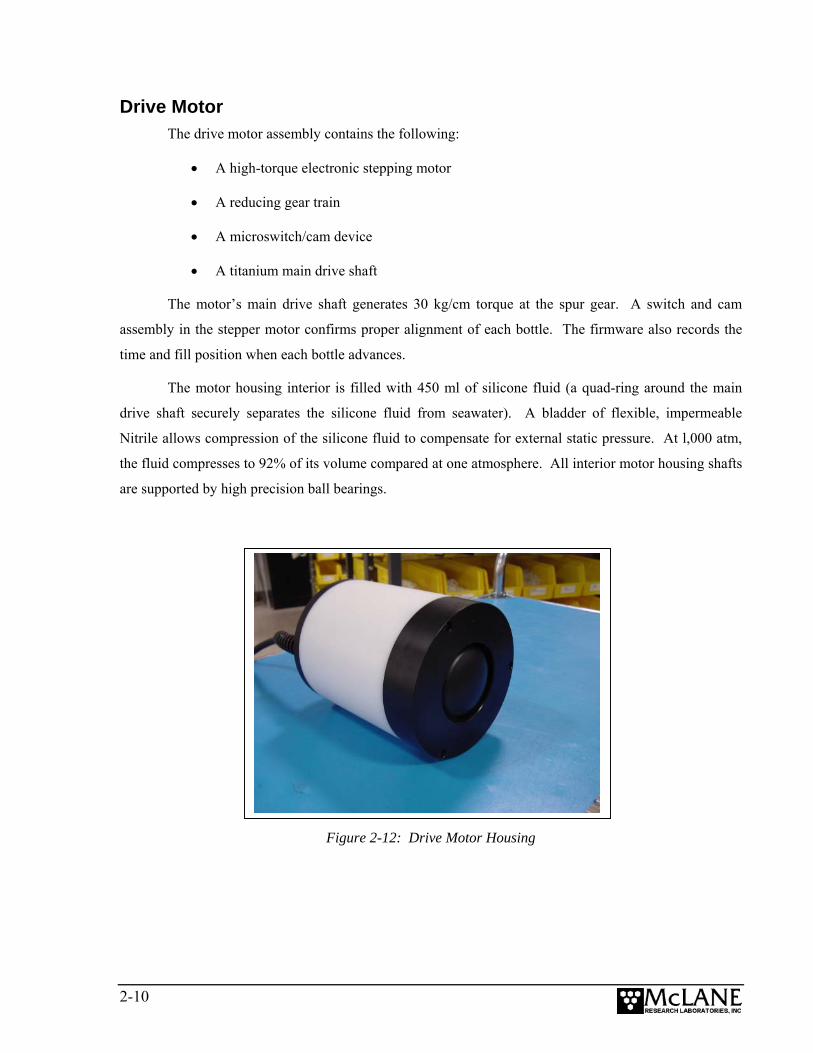
Drive Motor The drive motor assembly contains the following:
• A high-torque electronic stepping motor
• A reducing gear train
• A microswitch/cam device
• A titanium main drive shaft
The motor’s main drive shaft generates 30 kg/cm torque at the spur gear. A switch and cam
assembly in the stepper motor confirms proper alignment of each bottle. The firmware also records the
time and fill position when each bottle advances.
The motor housing interior is filled with 450 ml of silicone fluid (a quad-ring around the main
drive shaft securely separates the silicone fluid from seawater). A bladder of flexible, impermeable
Nitrile allows compression of the silicone fluid to compensate for external static pressure. At l,000 atm,
the fluid compresses to 92% of its volume compared at one atmosphere. All interior motor housing shafts
are supported by high precision ball bearings.
Figure 2-12: Drive Motor Housing
2-10
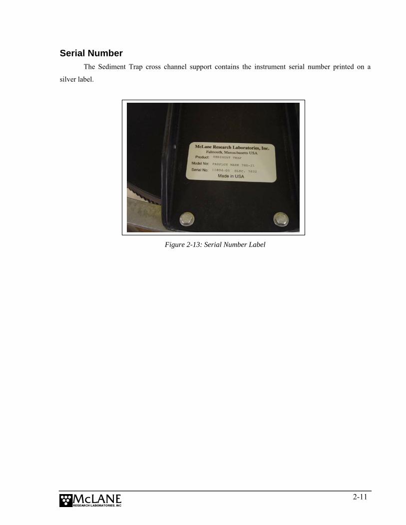
Serial Number The Sediment Trap cross channel support contains the instrument serial number printed on a
silver label.
Figure 2-13: Serial Number Label
2-11

Notes
2-12

Chapter 3 Electronic Description Controller Electronics Stack
The Trap controller is a two board electronics stack mounted on the chassis plate between
the controller housing end cap and the battery holder. The electronics boards contain a low
power data logger and a stepper motor driver. To operate, connect the micro-controller to an
external PC with a communications protocol set to 9600 baud, 8 data bits, 1 stop bit, and no
parity. The micro-controller automatically starts when the batteries are connected.
Figure 3-1: Sediment Trap Controller Stack
NOTE
An optional Compass/Tilt Sensor can be installed to provide a time history of tilt magnitude and
direction. If this option is used, the electronics is a three board stack (a sensor board is added).
For more information, see Appendix B, “Optional Compass/Tilt Sensor” in this User Manual.
IMPORTANT
McLane recommends following standard electrostatic discharge (ESD) precautions when
handling the electronics.
3-1
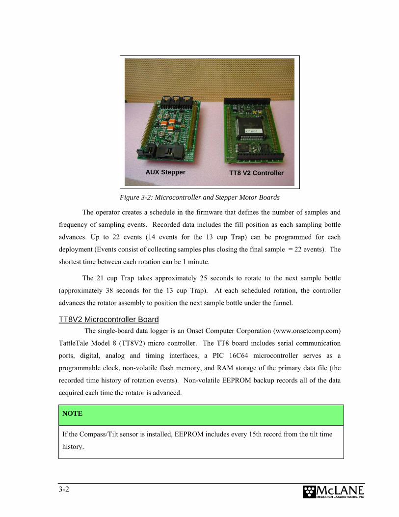
TT8 V2 Controller AUX Stepper
Figure 3-2: Microcontroller and Stepper Motor Boards
The operator creates a schedule in the firmware that defines the number of samples and
frequency of sampling events. Recorded data includes the fill position as each sampling bottle
advances. Up to 22 events (14 events for the 13 cup Trap) can be programmed for each
deployment (Events consist of collecting samples plus closing the final sample = 22 events). The
shortest time between each rotation can be 1 minute.
The 21 cup Trap takes approximately 25 seconds to rotate to the next sample bottle
(approximately 38 seconds for the 13 cup Trap). At each scheduled rotation, the controller
advances the rotator assembly to position the next sample bottle under the funnel.
TT8V2 Microcontroller Board The single-board data logger is an Onset Computer Corporation (www.onsetcomp.com)
TattleTale Model 8 (TT8V2) micro controller. The TT8 board includes serial communication
ports, digital, analog and timing interfaces, a PIC 16C64 microcontroller serves as a
programmable clock, non-volatile flash memory, and RAM storage of the primary data file (the
recorded time history of rotation events). Non-volatile EEPROM backup records all of the data
acquired each time the rotator is advanced.
NOTE
If the Compass/Tilt sensor is installed, EEPROM includes every 15th record from the tilt time
history.
3-2

AUX Stepper Motor Circuit Board The AUX Stepper motor circuit board controls power, communications, and the stepper
motor. There are four connectors on the top of the stepper driver board:
• Amp MTE 2-pin for the main battery
• Amp MTE 8-pin for the stepper motor
• Amp MTE 4-pin for the communications
• Molex 2-pin for the 9 Volt battery backup
Battery Connection/Powering on the Trap Connecting and disconnecting the battery is the only way to power the Sediment Trap on
and off. The firmware starts automatically when either the main or backup battery is connected.
The main battery pack is a white, PVC plastic cylinder that holds 14 “C” cell alkaline
batteries. A new set of batteries provides at least 21 volts with 5Ah capacity. The main batteries
are connected to each other in series via two circuit boards internal to the battery housing. The
positive and negative terminators of the main battery assembly are fed through the top cap of the
assembly for connection to the electronics assembly.
Figure 3-3: Sediment Trap Main Battery Pack
3-3
To power on the Sediment Trap and connect to a PC, complete the following steps:
1. Boot the operator PC and start the communications software.
2. Place the Trap in a dry area and open the controller housing by unscrewing the
three (3) bolts from the end cap (the cap with the connectors mounted to it).
3. Pull the end cap straight out from the cylinder. The controller, computer, and
batteries are mounted to this end cap.
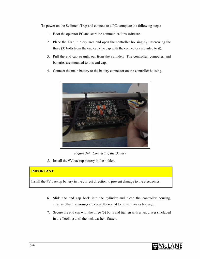
4. Connect the main battery to the battery connector on the controller housing.
Figure 3-4: Connecting the Battery
5. Install the 9V backup battery in the holder.
IMPORTANT
Install the 9V backup battery in the correct direction to prevent damage to the electroincs.
6. Slide the end cap back into the cylinder and close the controller housing,
ensuring that the o-rings are correctly seated to prevent water leakage.
7. Secure the end cap with the three (3) bolts and tighten with a hex driver (included
in the Toolkit) until the lock washers flatten.
3-4
NOTE
Do not overtighten bolts.
8. Remove the dummy plug from the COM connector on the controller housing end
cap.
9. Attach the communication cable (supplied in the Toolkit) to the PC serial port
first and then to the COM connector.
IMPORTANT
Always make and break the COM connection at the controller housing rather than the PC serial
port to avoid crashing the TT8 controller.
10. Press [CTRL]-[C] three times to display the Main Menu.
NOTE
If the Main Menu does not display, check the COM port connection and confirm the
communication protocol settings (9600 baud, 8 data bits, 1 stop bit, and no parity).
11. Before disconnecting power, press [CTRL]-[C] to return to the Main Menu and
select Sleep.
3-5

Notes
3-6
Chapter 4 Maintenance and Storage
Rinsing the entire Sediment Trap thoroughly with clean, fresh water before and after
every deployment helps prevent corrosion. Maintenance before and after each deployment also
includes:
• Cleaning and Inspecting the Controller Housing
• Inspecting the Drive Motor Assembly
• Cleaning and Inspecting the O-rings
• Tightening Bolts
• Inspecting the Drive Motor
• Inspecting the Rotator Plate
• Replacing Batteries
Steps for preparing the Sediment Trap for storage are also included in this Chapter.
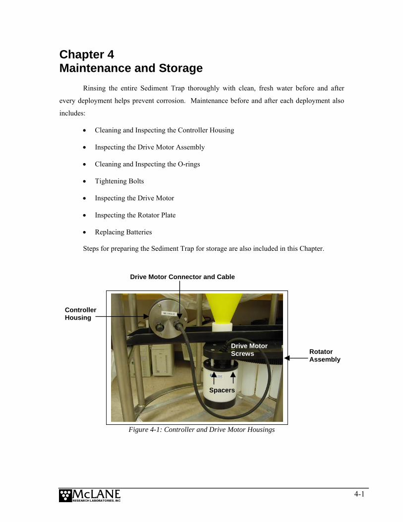
Figure 4-1: Controller and Drive Motor Housings
Drive Motor Screws
Drive Motor Connector and Cable
Controller Housing
Rotator Assembly
Spacers
4-1
Cleaning and Inspecting the Controller Housing Visually inspect the controller housing before deployment. Confirm that the securing
loops (u-bolts) on the rotator plate assembly are tightened and the drive motor cable is connected
to the controller housing. Secure the drive motor connector by screwing the connector locking
sleeve on.
Tighten the securing loops (u-bolts) onto the controller housing chassis, confirming that
the rubber insulation is properly positioned to keep the controller housing from contacting the
metal on the securing loops. Secure the lock-washers but do not overtighten.
O-Rings The end cap is sealed with a set of Buna N o-rings, two 70 durometer o-rings (3-612 and
2-152), and one 90 durometer backup ring (8-152). To prevent leaks, these o-rings must be
exceptionally clean, installed properly, and kept in place at all times. Inspect the o-rings for signs
of wear such as cracks and the presence of foreign material that could affect the seal (such as hair
or grit).
When positioning o-rings, the backup o-ring should be on the low pressure side of the
radial groove, toward the interior of the controller housing. The backup o-ring concave side faces
toward the round o-ring. Apply o-ring grease prior to installing o-rings.
Inspecting the Drive Motor Assembly Visually inspect the drive motor cable and housing assembly before deployment.
Confirm that the compensating oil bladder has sufficient silicone oil (the oil can be topped off if
necessary).
To inspect the drive motor oil bladder, complete the following steps:
1. With the drive motor still connected to the rotator assembly, place an index
finger on the oil bladder located at the bottom of the drive motor housing and
press gently.
4-2
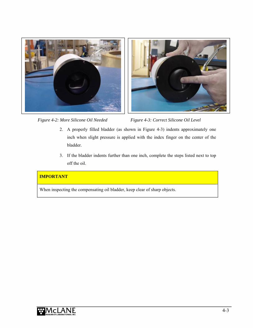
Figure 4-2: More Silicone Oil Needed Figure 4-3: Correct Silicone Oil Level
2. A properly filled bladder (as shown in Figure 4-3) indents approximately one
inch when slight pressure is applied with the index finger on the center of the
bladder.
3. If the bladder indents further than one inch, complete the steps listed next to top
off the oil.
IMPORTANT
When inspecting the compensating oil bladder, keep clear of sharp objects.
4-3

Adding Oil to the Drive Motor To top off the oil in the compensating bladder, complete the following steps:
1. Unplug the drive motor cable from the controller housing.
2. Remove and set aside the three (3) screws and spacers that secure the drive motor
to the rotator assembly.
3. Place the drive motor housing upright on a dry surface.
4. Hold the drive motor housing firmly at the bottom and side and slowly unscrew
the fill plug at the top of the drive motor housing.
5. Insert a funnel or syringe into the fill hole (as shown in Figure 4-4) and slowly
pour in silicone oil while gently pressing up on the bladder to ‘burp’ out air
bubbles. (The oil will be drawn into the fill hole as the air bubbles are released).
Figure 4-4: Adding Silicone Oil
4-4
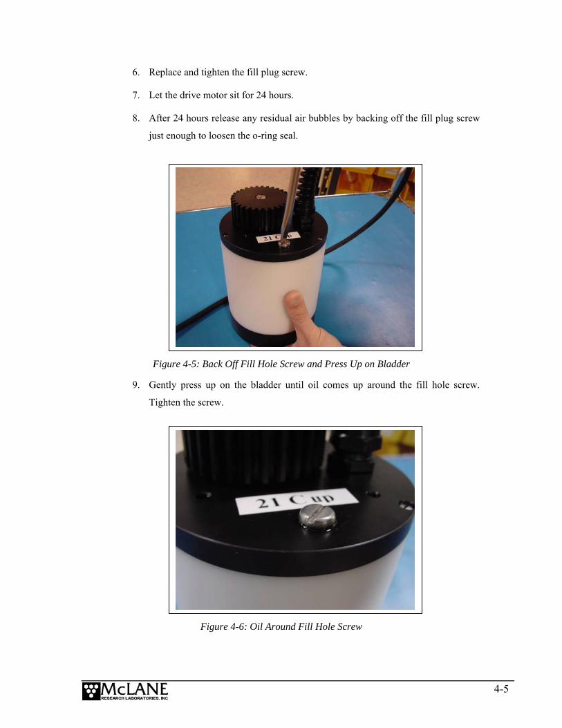
6. Replace and tighten the fill plug screw.
7. Let the drive motor sit for 24 hours.
8. After 24 hours release any residual air bubbles by backing off the fill plug screw
just enough to loosen the o-ring seal.
Figure 4-5: Back Off Fill Hole Screw and Press Up on Bladder
9. Gently press up on the bladder until oil comes up around the fill hole screw.
Tighten the screw.
Figure 4-6: Oil Around Fill Hole Screw
4-5
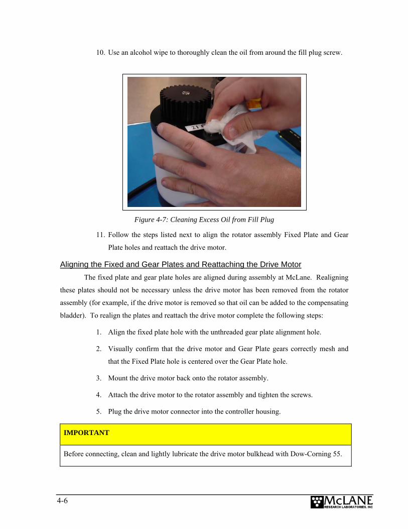
10. Use an alcohol wipe to thoroughly clean the oil from around the fill plug screw.
Figure 4-7: Cleaning Excess Oil from Fill Plug
11. Follow the steps listed next to align the rotator assembly Fixed Plate and Gear
Plate holes and reattach the drive motor.
Aligning the Fixed and Gear Plates and Reattaching the Drive Motor The fixed plate and gear plate holes are aligned during assembly at McLane. Realigning
these plates should not be necessary unless the drive motor has been removed from the rotator
assembly (for example, if the drive motor is removed so that oil can be added to the compensating
bladder). To realign the plates and reattach the drive motor complete the following steps:
1. Align the fixed plate hole with the unthreaded gear plate alignment hole.
2. Visually confirm that the drive motor and Gear Plate gears correctly mesh and
that the Fixed Plate hole is centered over the Gear Plate hole.
3. Mount the drive motor back onto the rotator assembly.
4. Attach the drive motor to the rotator assembly and tighten the screws.
5. Plug the drive motor connector into the controller housing.
IMPORTANT
Before connecting, clean and lightly lubricate the drive motor bulkhead with Dow-Corning 55.
4-6
Replacing Batteries Using fresh Duracell batteries for each deployment is strongly recommended (a new
battery pack has a 5,000 mAhr capacity).
IMPORTANT
Installing the “C” cell batteries with the correct polarity is essential.
Battery Installation Selecting <2> Diagnostics from the Main Menu displays battery voltage. Batteries with
less than 18 V should be replaced before the next deployment (battery packs below 18 V trigger a
warning message and voltage below 12 V triggers a critically low battery voltage message). For
details about diagnostics and battery voltage messages, see Chapter 7 in this User Manual.
IMPORTANT
When the Compass/Tilt sensor is installed, degausse new batteries before placing in the battery
holder. See Appendix B, “Optional Compass/Tilt Sensor” in this User Manual for more detail.
To change the batteries, complete the following steps:
1. Place the Trap in a dry area.
2. Open the controller housing and disconnect the main battery from the electronics
assembly. Move the electronics assembly end cap to a grounded electronics bench.
IMPORTANT
Offload all deployment data before removing the main battery. All data except the non-volatile
backup cache is lost when the battery is disconnected (unless the backup battery is in place).
4-7
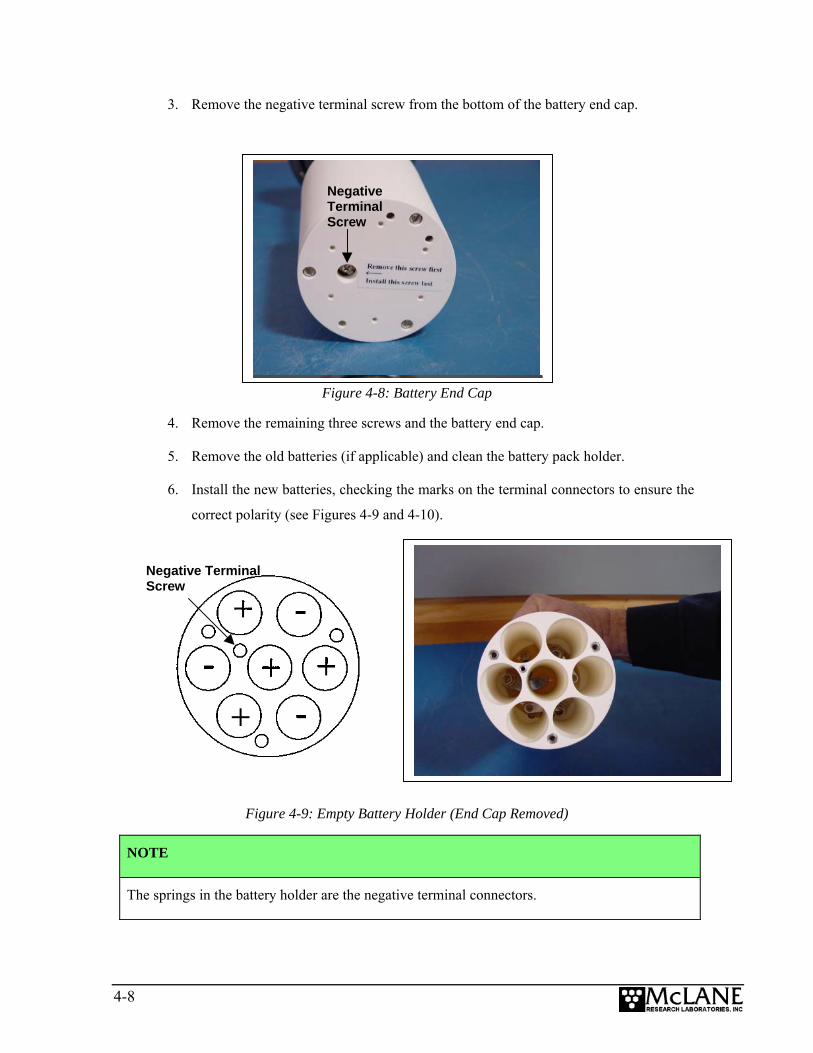
3. Remove the negative terminal screw from the bottom of the battery end cap.
Figure 4-8: Battery End Cap
4. Remove the remaining three screws and the battery end cap.
5. Remove the old batteries (if applicable) and clean the battery pack holder.
6. Install the new batteries, checking the marks on the terminal connectors to ensure the
correct polarity (see Figures 4-9 and 4-10).
Negative Terminal Screw
Negative Terminal Screw
Figure 4-9: Empty Battery Holder (End Cap Removed)
NOTE
The springs in the battery holder are the negative terminal connectors.
4-8
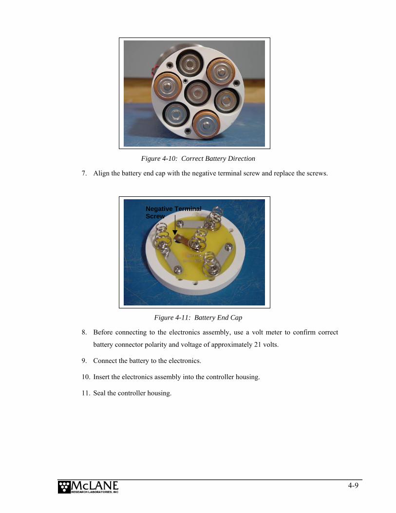
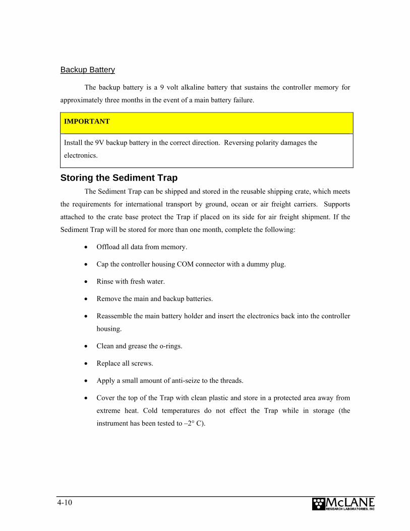
Figure 4-10: Correct Battery Direction
7. Align the battery end cap with the negative terminal screw and replace the screws.
Negative Terminal Screw
Figure 4-11: Battery End Cap
8. Before connecting to the electronics assembly, use a volt meter to confirm correct
battery connector polarity and voltage of approximately 21 volts.
9. Connect the battery to the electronics.
10. Insert the electronics assembly into the controller housing.
11. Seal the controller housing.
4-9
Backup Battery
The backup battery is a 9 volt alkaline battery that sustains the controller memory for
approximately three months in the event of a main battery failure.
IMPORTANT
Install the 9V backup battery in the correct direction. Reversing polarity damages the
electronics.
Storing the Sediment Trap The Sediment Trap can be shipped and stored in the reusable shipping crate, which meets
the requirements for international transport by ground, ocean or air freight carriers. Supports
attached to the crate base protect the Trap if placed on its side for air freight shipment. If the
Sediment Trap will be stored for more than one month, complete the following:
• Offload all data from memory.
• Cap the controller housing COM connector with a dummy plug.
• Rinse with fresh water.
• Remove the main and backup batteries.
• Reassemble the main battery holder and insert the electronics back into the controller
housing.
• Clean and grease the o-rings.
• Replace all screws.
• Apply a small amount of anti-seize to the threads.
• Cover the top of the Trap with clean plastic and store in a protected area away from
extreme heat. Cold temperatures do not effect the Trap while in storage (the
instrument has been tested to –2° C).
4-10
Chapter 5 Operations
Each sample bottle must be rinsed, filled, and attached to the rotator assembly prior to
deployment. Deploying the Trap with full sample bottles prevents the bottles from crushing at
depth. The rotator must also be aligned to the open hole (‘zero’ port). Steps for completing these
pre-deployment processes and examples for calculating estimated deployment battery duration
are included in this Chapter.
Preparing and Attaching Sample Bottles Before filling bottles, wash and rinse them with neutral/distilled water. After bottles are
thoroughly dried, number them on the outside with a permanent marker.
To attach the sample bottles to the rotator assembly, complete the following steps:
1. Slide one silicone o-ring to the shoulder of each sample bottle.
2. Fill each sample bottle approximately 7/8 full with neutral water, or water
collected from the deployment depth.
3. Screw the sample bottles in order (as numbered on the outside of each bottle) into
the holes on the Gear Plate and hand-tighten.
4. Looking up at the Gear Plate, confirm that the numbered bottles are in the proper
order.
5. Remove the fill plug on the rotator assembly.
6. Boot the PC and plug the COM cable into the PC serial port.
7. Connect the COM cable to the Sediment Trap controller housing.
8. From the Sediment Trap Main Menu select <3> Fill Bottles.
9. Confirm the Bottom Fixed Plate and Gear Plate holes are aligned.
10. Using a squirt bottle full of neutral water, top off each bottle until completely
full.
11. When prompted, type ‘Y’ to move to the next bottle. Repeat this step until all
sample bottles are filled.
12. Replace the fill plug.
5-1
13. Advance the rotator assembly until the alignment hole (the open hole without
threads) is underneath the funnel. This is referred to as setting the rotator
assembly to ‘zero’.
14. Type ‘N’ when prompted to move to the next bottle.
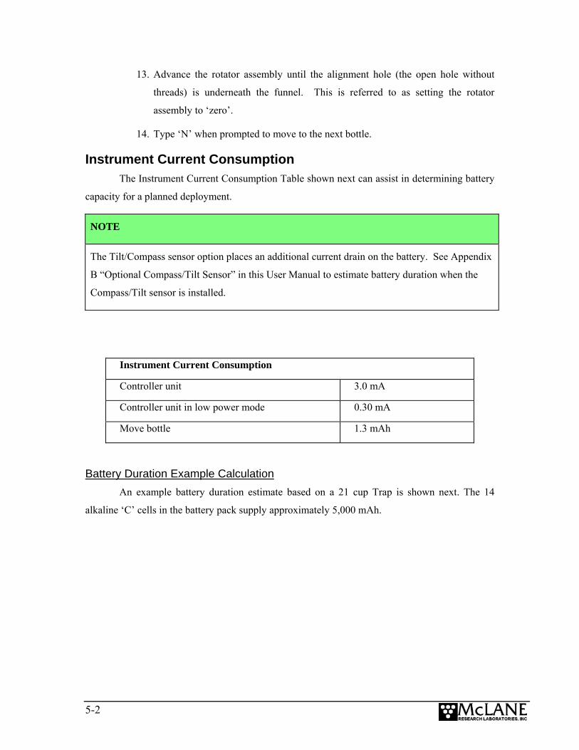
Instrument Current Consumption The Instrument Current Consumption Table shown next can assist in determining battery
capacity for a planned deployment.
NOTE
The Tilt/Compass sensor option places an additional current drain on the battery. See Appendix
B “Optional Compass/Tilt Sensor” in this User Manual to estimate battery duration when the
Compass/Tilt sensor is installed.
Instrument Current Consumption
Controller unit 3.0 mA
Controller unit in low power mode 0.30 mA
Move bottle 1.3 mAh
Battery Duration Example Calculation An example battery duration estimate based on a 21 cup Trap is shown next. The 14
alkaline ‘C’ cells in the battery pack supply approximately 5,000 mAh.
5-2
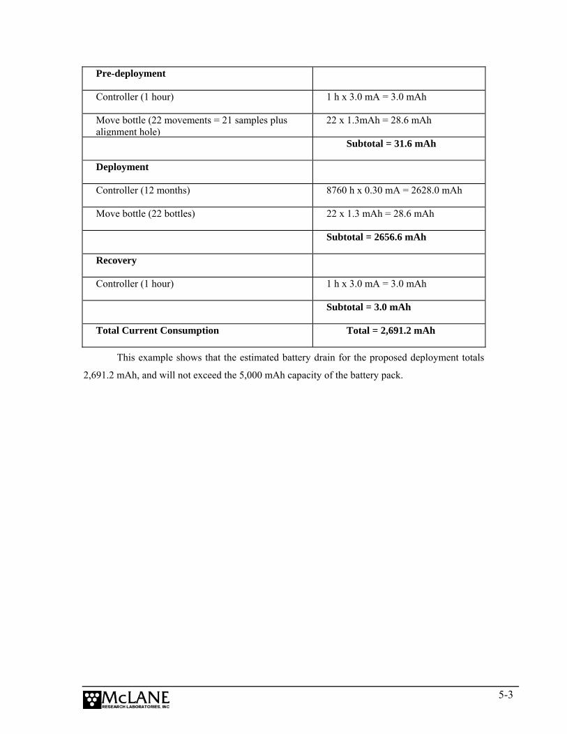
Pre-deployment
Controller (1 hour) 1 h x 3.0 mA = 3.0 mAh
Move bottle (22 movements = 21 samples plus alignment hole)
22 x 1.3mAh = 28.6 mAh
Subtotal = 31.6 mAh
Deployment
Controller (12 months) 8760 h x 0.30 mA = 2628.0 mAh
Move bottle (22 bottles) 22 x 1.3 mAh = 28.6 mAh
Subtotal = 2656.6 mAh
Recovery
Controller (1 hour) 1 h x 3.0 mA = 3.0 mAh
Subtotal = 3.0 mAh
Total Current Consumption Total = 2,691.2 mAh
This example shows that the estimated battery drain for the proposed deployment totals
2,691.2 mAh, and will not exceed the 5,000 mAh capacity of the battery pack.
5-3

Notes
5-4
Chapter 6 Launch and Recovery
Prior to launching the Sediment Trap, the following is required (in order of completion):
1 − Connect the battery (Chapter 4)
2 − Close the end cap
3 − Connect the Sediment Trap COM cable and program the deployment
4 − Disconnect COM cable and attach the dummy plug
5 − Attach to a mooring
This Chapter provides steps for connecting to a mooring and draining the trap to remove
the sample bottles when the Trap is recovered.
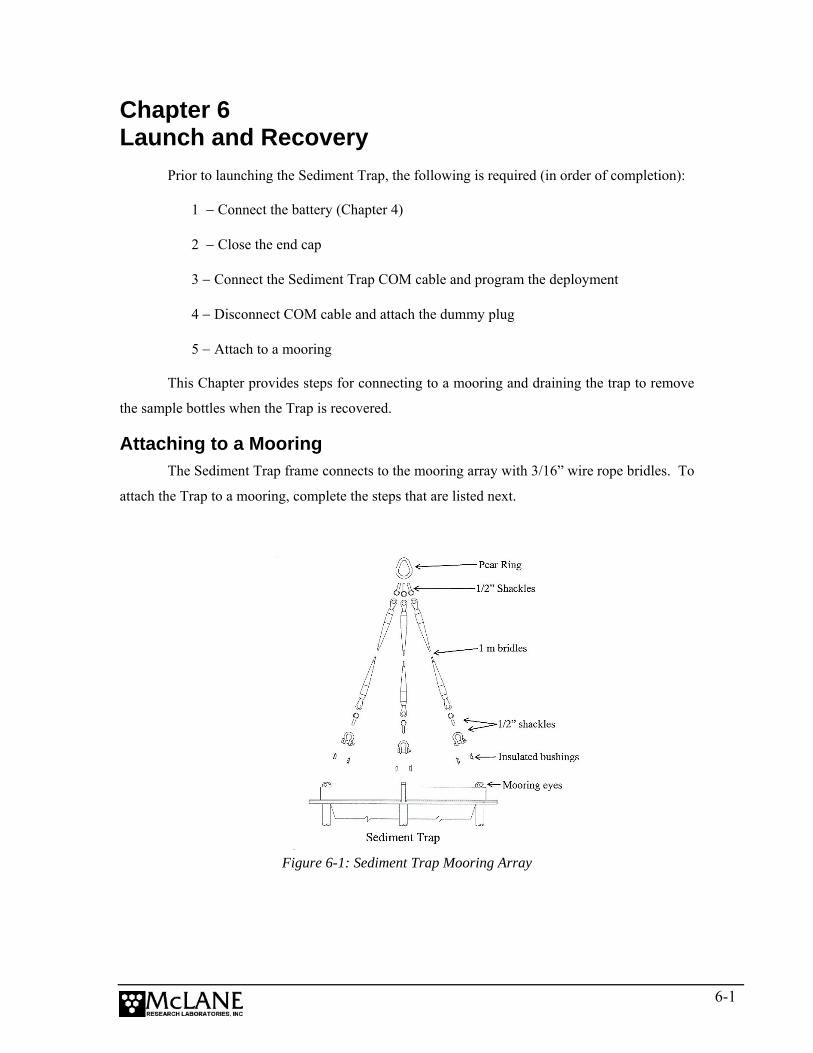
Attaching to a Mooring The Sediment Trap frame connects to the mooring array with 3/16” wire rope bridles. To
attach the Trap to a mooring, complete the steps that are listed next.
Figure 6-1: Sediment Trap Mooring Array
6-1
1. Place the insulating (black) Acetel bushings into each side of the Sediment
Trap’s top mooring eyes.
2. Install a 1/2” shackle through the insulated mooring eye.
3. Loop another shackle through the first shackle and connect it to the 1m bridle.
4. Repeat Steps 1 through 3 for the rest of the mooring eyes.
5. Loop three shackles around the pear ring (weldless sling link) and connect it to
the ends of the three 1m lengths of wire (a single pear ring should be connected
to three 1m lengths of wire which are connected to the Sediment Trap).
6. Repeat the previous steps for the bottom mooring eyes (using 3/8” chain instead
of wire).
7. Connect the pear-rings to the rest of the mooring system.
Recovery Procedure • After the deployment is completed and the funnel is drained the sample bottles
must be removed.
• Remove the sample bottles.
NOTE
Steps for offloading the data are included in Chapter 8, “Data Offload and Processing” in this
User Manual.
Removing the Sample Bottles After the deployment is completed, the firmware positions the alignment hole under the
funnel to seal the samples from ambient water. To remove the sample bottles, complete the
following steps:
1. Confirm that the funnel is drained (water in the funnel should drain quickly while
the Trap is lifted to the deck).
2. If drainage is restricted by incomplete rotation, unscrew the sample bottle that is
directly under the collecting hole. All the samples will be protected except for
this last sample.
6-2
3. Disconnect the Trap from the mooring through the pear-ring and secure in a
protected area.
NOTE
Use caution when handling the disconnected bridles. Dropping bridles onto the top of the Trap
cone can damage the honeycomb baffle.
4. Remove the sample bottles and cover securely with the screw-on lids.
5. Store the samples in a clean refrigerated area.
6. Perform any necessary maintenance on the trap (see Chapter 4 “Maintenance and
Storage” in this User Manual for maintenance procedures).
6-3

Notes
6-4

Chapter 7 Sediment Trap User Interface
This chapter describes the Sediment Trap firmware including menus, commands, screens
and deployment programming.
NOTE
Additional menu options and commands display in the Trap firmware version that supports the
Compass/Tilt sensor option. For more information, see Appendix B in this User Manual,
“Optional Compass/Tilt Sensor”.
Power-Up Sequence Connecting the Trap battery automatically loads the TT8 RAM (and is the only way to
power on the system). When the power-up sequence begins, a screen prompt displays to set the
time and date.
Clock reads 01/01/70 00:05:26 Change time & date (Yes/No) [N] ? y (Note: Year 2000=100, 2001=101, etc.) Enter correct time [01/01/70 00:00:51] ? 08-29-102 9-59-40 Clock reads 08/29/02 09:59:40 Change time & date (Yes/No) [N] ? n
Figure 7-1: Set Time display
NOTE
If the time and date screens do not display and the battery has been connected for some time, the
firmware may be in Low Power Sleep (LPS). Press [CTRL]-[C] three times to wake the system.
If the screens still do not display, confirm the COM port connection and communication
protocol settings (9600 baud, 8 data bits, 1 stop bit, and no parity).
Main Menu – Operating the Sediment Trap The Sediment Trap Main Menu provides the selections for all system control operations
and displays the instrument serial number and firmware version. To select an option, type an
alphanumeric character and press [ENTER].
7-1

NOTE
Pressing [ENTER] accepts the default for most prompts in the firmware.
McLane Research Laboratories, USA Paraflux 21-cup Sediment Trap
Version: pst-21_0.c S/N ML11838-01
Main Menu
Thu Jan 1 02:00:33 2001
<1> Set Time <5> Create Schedule <2> Diagnostics <6> Deploy System
<3> Fill Bottles <7> Offload Data <4> Sleep.... <8> Contacting MRL
Selection ?
Figure 7-2: Main Menu display
<1> Set Time This option sets or adjusts the real time clock (RTC). See Figure 7-1 for the Set Time
display. Until it is set, the RTC defaults to January 1, 1970, 00:00:00. Clock settings are:
MM:DD:YYYY. Time settings are: HH:MM:SS.
IMPORTANT
Since McLane recommends that the RTC initially be set during the power-up sequence. Hence,
the Set Time option should be necessary only to adjust the date and/or time. The RTC can be
set to any date and time in the allowed range and the count will continue from the new value.
NOTE
Spaces or colons can be used as separators. Leading zeros (01 rather than 1) are optional. The
Year (for example, 2004) can be entered as ‘4’, ‘104’, or ‘2004’.
7-2
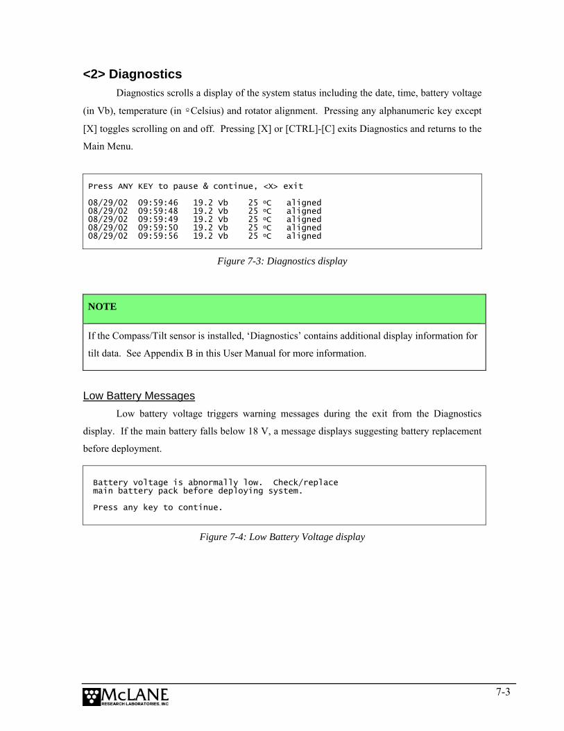
<2> Diagnostics Diagnostics scrolls a display of the system status including the date, time, battery voltage
(in Vb), temperature (in ºCelsius) and rotator alignment. Pressing any alphanumeric key except
[X] toggles scrolling on and off. Pressing [X] or [CTRL]-[C] exits Diagnostics and returns to the
Main Menu.
Press ANY KEY to pause & continue, <X> exit 08/29/02 09:59:46 19.2 Vb 25 oC aligned 08/29/02 09:59:48 19.2 Vb 25 oC aligned 08/29/02 09:59:49 19.2 Vb 25 oC aligned 08/29/02 09:59:50 19.2 Vb 25 oC aligned 08/29/02 09:59:56 19.2 Vb 25 oC aligned
Figure 7-3: Diagnostics display
NOTE
If the Compass/Tilt sensor is installed, ‘Diagnostics’ contains additional display information for
tilt data. See Appendix B in this User Manual for more information.
Low Battery Messages
Low battery voltage triggers warning messages during the exit from the Diagnostics
display. If the main battery falls below 18 V, a message displays suggesting battery replacement
before deployment.
Battery voltage is abnormally low. Check/replace main battery pack before deploying system. Press any key to continue.
Figure 7-4: Low Battery Voltage display
7-3
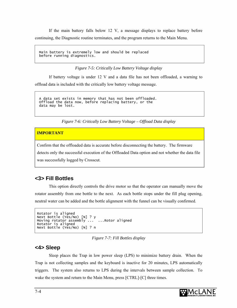
If the main battery falls below 12 V, a message displays to replace battery before
continuing, the Diagnostic routine terminates, and the program returns to the Main Menu.
Main battery is extremely low and should be replaced before running diagnostics.
Figure 7-5: Critically Low Battery Voltage display
If battery voltage is under 12 V and a data file has not been offloaded, a warning to
offload data is included with the critically low battery voltage message.
A data set exists in memory that has not been offloaded. Offload the data now, before replacing battery, or the data may be lost.
Figure 7-6: Critically Low Battery Voltage – Offload Data display
IMPORTANT
Confirm that the offloaded data is accurate before disconnecting the battery. The firmware
detects only the successful execution of the Offloaded Data option and not whether the data file
was successfully logged by Crosscut.
<3> Fill Bottles This option directly controls the drive motor so that the operator can manually move the
rotator assembly from one bottle to the next. As each bottle stops under the fill plug opening,
neutral water can be added and the bottle alignment with the funnel can be visually confirmed.
Rotator is aligned Next Bottle (Yes/No) [N] ? y Moving rotator assembly ... ...Rotor aligned Rotator is aligned Next Bottle (Yes/No) [N] ? n
Figure 7-7: Fill Bottles display
<4> Sleep Sleep places the Trap in low power sleep (LPS) to minimize battery drain. When the
Trap is not collecting samples and the keyboard is inactive for 20 minutes, LPS automatically
triggers. The system also returns to LPS during the intervals between sample collection. To
wake the system and return to the Main Menu, press [CTRL]-[C] three times.
7-4

<5> Create Schedule Create Schedule defines the number of samples and frequency of rotation events. A
maximum of 22 possible events (21 samples and the closing of the last sample) or 14 possible
events (13 samples and the closing of the last sample) can be scheduled. The schedule re-
displays for verification when <6> Deploy is selected.
Scheduling options are described below. Specific steps for creating the schedule are
provided in the “Programming for Deployment” section at the end of this Chapter.
Sampling Schedule Options
When <5> is selected, a warning message displays if data exists that has not been
offloaded (data that has not been offloaded is erased). Once a new schedule is entered and
confirmed, and the number of events to program is selected, the Schedule Menu displays.
SCHEDULE MENU
<1> Enter each event time <2> Enter start date & interval <3> Enter start date & end date <M> Main Menu
Selection? 3
Figure 7-8: Schedule Menu display A description of each schedule option is provided next.
<1> Enter each event time This option specifies the date and time for each rotation event and allows a unique
sampling period for each bottle. By entering each event time individually the scientist can
analyze the sediment from variable intervals.
<2> Enter start date & interval This option specifies a start date and a fixed time interval between each event.
Scheduling in this manner is beneficial for a deployment with a fixed start date and a consistent
sample period.
7-5
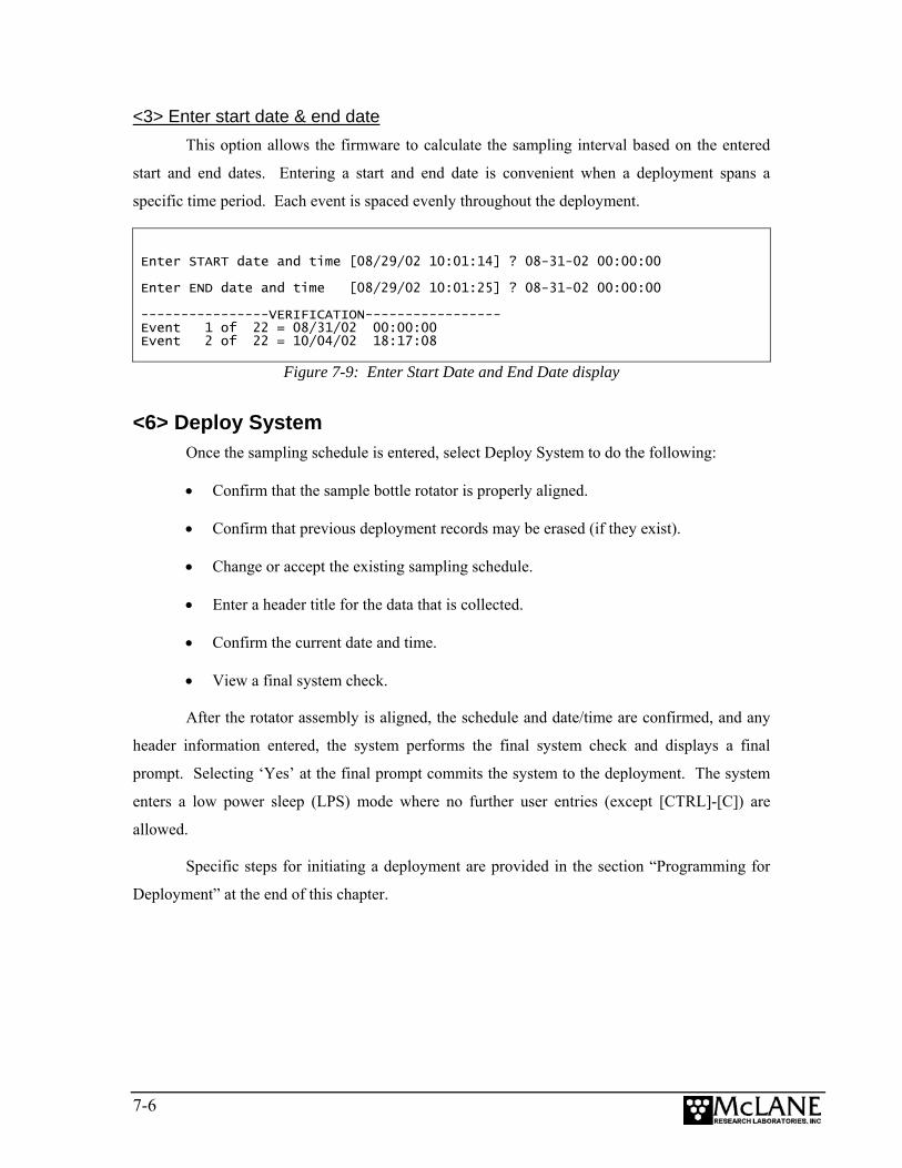
<3> Enter start date & end date This option allows the firmware to calculate the sampling interval based on the entered
start and end dates. Entering a start and end date is convenient when a deployment spans a
specific time period. Each event is spaced evenly throughout the deployment.
Enter START date and time [08/29/02 10:01:14] ? 08-31-02 00:00:00 Enter END date and time [08/29/02 10:01:25] ? 08-31-02 00:00:00 ----------------VERIFICATION----------------- Event 1 of 22 = 08/31/02 00:00:00 Event 2 of 22 = 10/04/02 18:17:08
Figure 7-9: Enter Start Date and End Date display
<6> Deploy System Once the sampling schedule is entered, select Deploy System to do the following:
• Confirm that the sample bottle rotator is properly aligned.
• Confirm that previous deployment records may be erased (if they exist).
• Change or accept the existing sampling schedule.
• Enter a header title for the data that is collected.
• Confirm the current date and time.
• View a final system check.
After the rotator assembly is aligned, the schedule and date/time are confirmed, and any
header information entered, the system performs the final system check and displays a final
prompt. Selecting ‘Yes’ at the final prompt commits the system to the deployment. The system
enters a low power sleep (LPS) mode where no further user entries (except [CTRL]-[C]) are
allowed.
Specific steps for initiating a deployment are provided in the section “Programming for
Deployment” at the end of this chapter.
7-6
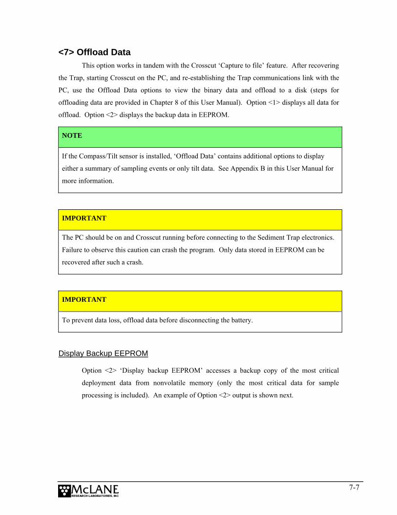
<7> Offload Data This option works in tandem with the Crosscut ‘Capture to file’ feature. After recovering
the Trap, starting Crosscut on the PC, and re-establishing the Trap communications link with the
PC, use the Offload Data options to view the binary data and offload to a disk (steps for
offloading data are provided in Chapter 8 of this User Manual). Option <1> displays all data for
offload. Option <2> displays the backup data in EEPROM.
NOTE
If the Compass/Tilt sensor is installed, ‘Offload Data’ contains additional options to display
either a summary of sampling events or only tilt data. See Appendix B in this User Manual for
more information.
IMPORTANT
The PC should be on and Crosscut running before connecting to the Sediment Trap electronics.
Failure to observe this caution can crash the program. Only data stored in EEPROM can be
recovered after such a crash.
IMPORTANT
To prevent data loss, offload data before disconnecting the battery.
Display Backup EEPROM
Option <2> ‘Display backup EEPROM’ accesses a backup copy of the most critical
deployment data from nonvolatile memory (only the most critical data for sample
processing is included). An example of Option <2> output is shown next.
7-7

Thu Jan 1 02:15:50 1970
<1> Display all data <2> Display backup EEPROM <M> Main Menu
Selection ? 2
During deployments a backup copy of the instrument data file is written to non-volatile EEPROM storage. This allows for data recovery in the unlikely event the instrument data file is no longer resident in active memory. To copy the EEPROM cache file to a disk file, initiate your communication program’s file logging command now and then press any key to start the transfer. The cache file remains resident in the EEPROM until overwritten during the next deployment. Event 01 Scheduled start time: 01/01/01 00:40:00 Event start time: 01/01/01 00:40:00 Event stop time: 01/01/01 00:42:00 Aligned Battery Temperature Start: Y 20.1 23 ºC Stop: Y 20.1 23 ºC Event 02 ...................... End of EEPROM data backup cache. Terminate file logging operation now and press any key to continue.
Offload/Display Data File
Figure 7-10: Display Backup EEPROM display
7-8
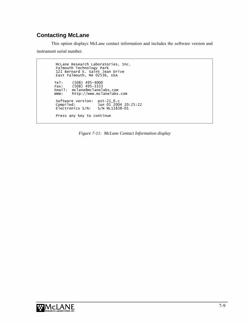
Contacting McLane This option displays McLane contact information and includes the software version and
instrument serial number.
McLane Research Laboratories, Inc. Falmouth Technology Park 121 Bernard E. Saint Jean Drive East Falmouth, MA 02536, USA Tel: (508) 495-4000 Fax: (508) 495-3333 Email: [email protected] WWW: http://www.mclanelabs.com Software version: pst-21_0.c Compiled: Jun 01 2004 20:25:22 Electronics S/N: S/N ML11838-01 Press any key to continue
Figure 7-11: McLane Contact Information display
7-9
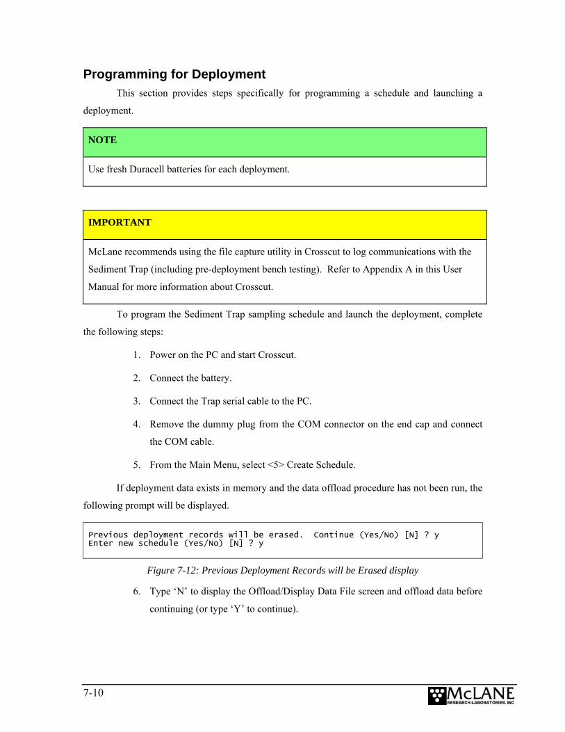
Programming for Deployment This section provides steps specifically for programming a schedule and launching a
deployment.
NOTE
Use fresh Duracell batteries for each deployment.
IMPORTANT
McLane recommends using the file capture utility in Crosscut to log communications with the
Sediment Trap (including pre-deployment bench testing). Refer to Appendix A in this User
Manual for more information about Crosscut.
To program the Sediment Trap sampling schedule and launch the deployment, complete
the following steps:
1. Power on the PC and start Crosscut.
2. Connect the battery.
3. Connect the Trap serial cable to the PC.
4. Remove the dummy plug from the COM connector on the end cap and connect
the COM cable.
5. From the Main Menu, select <5> Create Schedule.
If deployment data exists in memory and the data offload procedure has not been run, the
following prompt will be displayed.
Previous deployment records will be erased. Continue (Yes/No) [N] ? y Enter new schedule (Yes/No) [N] ? y
Figure 7-12: Previous Deployment Records will be Erased display
6. Type ‘N’ to display the Offload/Display Data File screen and offload data before
continuing (or type ‘Y’ to continue).
7-10
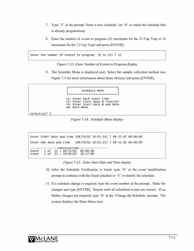
7. Type ‘Y’ at the prompt ‘Enter a new schedule’ (or ‘N’ to retain the schedule that
is already programmed).
8. Enter the number of events to program (22 maximum for the 21 Cup Trap or 14
maximum for the 13 Cup Trap) and press [ENTER].
Enter the number of events to program (0 to 22) ? 22
Figure 7-13: Enter Number of Events to Program display
9. The Schedule Menu is displayed next. Select the sample collection method (see
Figure 7-5 for more information about these choices) and press [ENTER].
SCHEDULE MENU
<1> Enter each event time <2> Enter start date & interval <3> Enter start date & end date <M> Main Menu
Selection? 3
Figure 7-14: Schedule Menu display
Enter START date and time [08/29/02 10:01:14] ? 08-31-02 00:00:00 Enter END date and time [08/29/02 10:01:25] ? 08-31-02 00:00:00 ----------------VERIFICATION----------------- Event 1 of 22 = 08/31/02 00:00:00 Event 2 of 22 = 10/04/02 18:17:08
Figure 7-15: Enter Start Date and Time display 10. After the Schedule Verification is listed, type ‘N’ at the event modification
prompt to continue with the listed schedule or ‘Y’ to modify the schedule.
11. If a schedule change is required, type the event number at the prompt. Make the
changes and type [ENTER]. Repeat until all scheduled events are correct. If no
further changes are required, type ‘N’ at the ‘Change the Schedule’ prompt. The
system displays the Main Menu next.
7-11
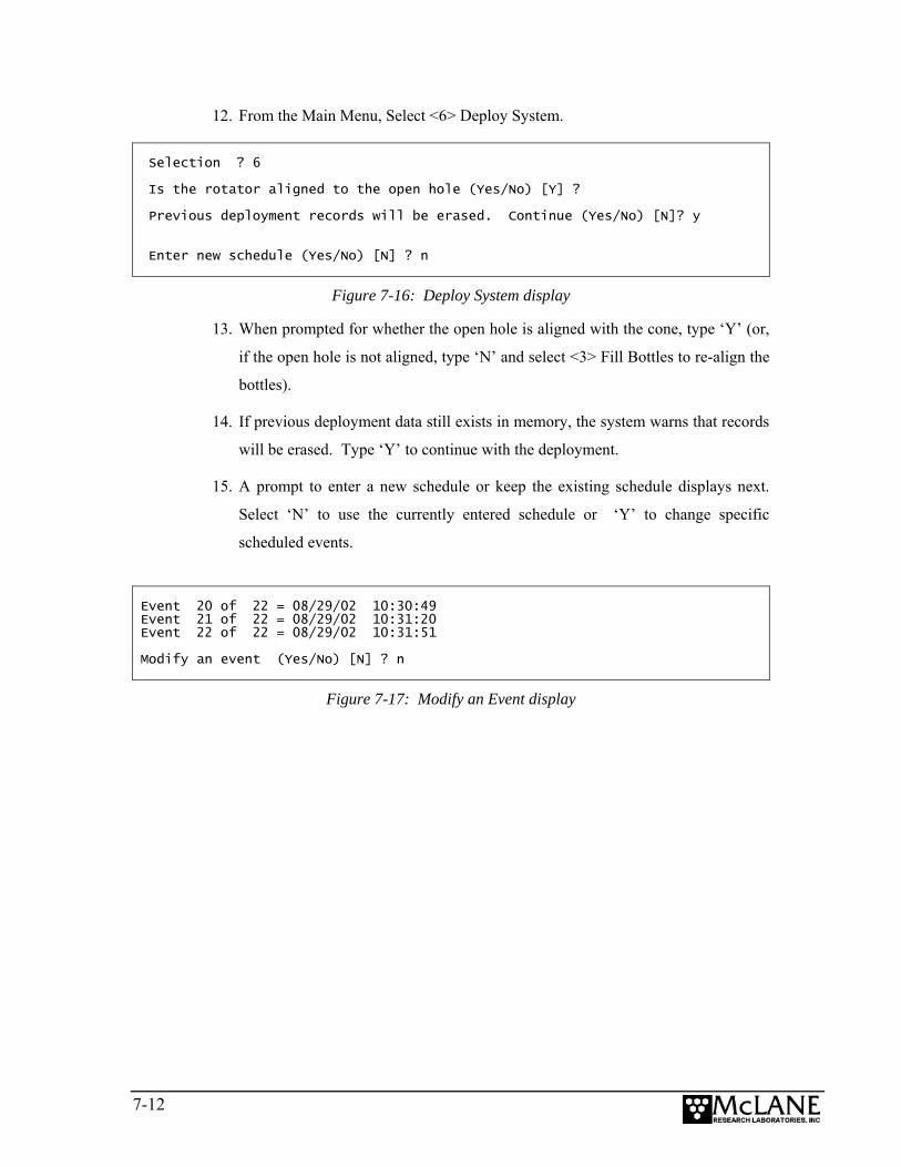
12. From the Main Menu, Select <6> Deploy System.
Selection ? 6 Is the rotator aligned to the open hole (Yes/No) [Y] ? Previous deployment records will be erased. Continue (Yes/No) [N]? y Enter new schedule (Yes/No) [N] ? n
Figure 7-16: Deploy System display
13. When prompted for whether the open hole is aligned with the cone, type ‘Y’ (or,
if the open hole is not aligned, type ‘N’ and select <3> Fill Bottles to re-align the
bottles).
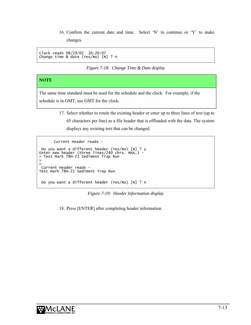
14. If previous deployment data still exists in memory, the system warns that records
will be erased. Type ‘Y’ to continue with the deployment.
15. A prompt to enter a new schedule or keep the existing schedule displays next.
Select ‘N’ to use the currently entered schedule or ‘Y’ to change specific
scheduled events.
Event 20 of 22 = 08/29/02 10:30:49 Event 21 of 22 = 08/29/02 10:31:20 Event 22 of 22 = 08/29/02 10:31:51 Modify an event (Yes/No) [N] ? n
Figure 7-17: Modify an Event display
7-12
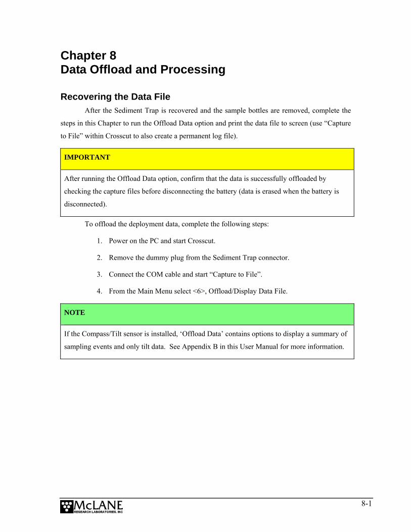
16. Confirm the current date and time. Select ‘N’ to continue or ‘Y’ to make
changes.
Clock reads 08/29/02 10:20:07 Change time & date (Yes/No) [N] ? n
Figure 7-18: Change Time & Date display
NOTE
The same time standard must be used for the schedule and the clock. For example, if the
schedule is in GMT, use GMT for the clock.
17. Select whether to retain the existing header or enter up to three lines of text (up to
65 characters per line) as a file header that is offloaded with the data. The system
displays any existing text that can be changed.
Current Header reads - Do you want a different header (Yes/No) [N] ? y Enter new header (three lines/240 chrs. MAX.) - > Test Mark 78H-21 Sediment Trap Run > > Current Header reads - Test Mark 78H-21 Sediment Trap Run Do you want a different header (Yes/No) [N] ? n
Figure 7-19: Header Information display
18. Press [ENTER] after completing header information.
7-13

19. A final system check is performed and a prompt displays to confirm deployment.
Typing ‘Y’ places the system in low power sleep (LPS) and redies the system for
deployment.
System shows the following - 08/29/02 10:20:41 18.9 Vb 31 ºC aligned Are you ready to deploy (Yes/No) [N] ? y System is ready. Remove communication cable & deploy
Figure 7-20: Deployment Confirmation display
7-14
Chapter 8 Data Offload and Processing
Recovering the Data File After the Sediment Trap is recovered and the sample bottles are removed, complete the
steps in this Chapter to run the Offload Data option and print the data file to screen (use “Capture
to File” within Crosscut to also create a permanent log file).
IMPORTANT
After running the Offload Data option, confirm that the data is successfully offloaded by
checking the capture files before disconnecting the battery (data is erased when the battery is
disconnected).
To offload the deployment data, complete the following steps:
1. Power on the PC and start Crosscut.
2. Remove the dummy plug from the Sediment Trap connector.
3. Connect the COM cable and start “Capture to File”.
4. From the Main Menu select <6>, Offload/Display Data File.
NOTE
If the Compass/Tilt sensor is installed, ‘Offload Data’ contains options to display a summary of
sampling events and only tilt data. See Appendix B in this User Manual for more information.
8-1

5. From the Offload/Display Data File menu, select <1> Display all data file. The
screen shown next displays.
<1> Display all data file <2> Display backup EEPROM <M> Main Menu Selection? 1 Software version: pst-21_0.c Compiled: Jun 11 2001 10:20:42 Electronics S/N: ML00000-00 Data recording start time = 01/01/01 00:34:16 Data recording stop time = 01/01/01 01:22:11 HEADER 21 bottle test SCHEDULE Event 01 of 22 @ 01/01/01 00:40:00 Event 02 of 22 @ 01/01/01 00:42:00 Event........... DEPLOYMENT DATA Event 01 Scheduled start time: 01/01/01 00:40:00 Event start time: 01/01/01 00:40:00 Event stop time: 01/01/01 00:40:28 Aligned Battery Temperature Start: Y 20.1 23 ºC Stop: Y 20.1 23 ºC Event............. End of instrument data file. Normal shutdown. Terminate file logging operation now and press any key to continue.
Offload/Display Data File
Figure 8-1: Offload/Display All Data File display
8-2
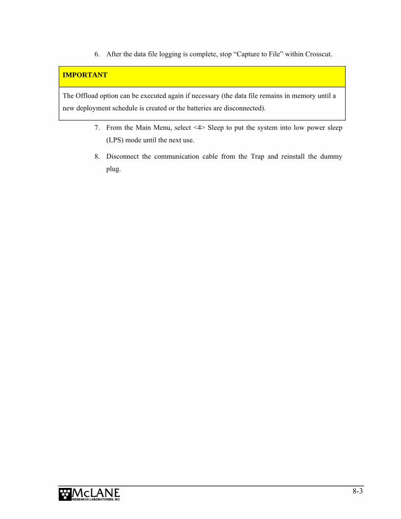
6. After the data file logging is complete, stop “Capture to File” within Crosscut.
IMPORTANT
The Offload option can be executed again if necessary (the data file remains in memory until a
new deployment schedule is created or the batteries are disconnected).
7. From the Main Menu, select <4> Sleep to put the system into low power sleep
(LPS) mode until the next use.
8. Disconnect the communication cable from the Trap and reinstall the dummy
plug.
8-3

Notes
8-4

Appendix A Operating Crosscut and Crosscut for Windows
You can use file logging during all of your interactions with the Sediment Trap to create
a log of operations, deployment settings, and recovery procedures. There are two standard file
capture programs that McLane recommends. Both programs are freely distributed by Onset
Computer (www.onsetcomp.com) for TT8 communication. Crosscut is a DOS-based program
that runs on a PC, and Crosscut for Win is Windows-based. McLane recommends using file
capture for all deployments.
To download compressed archives of Crosscut and Crosscut for Win software, go to:
www.mclanelabs.com/downloads/crosscut.zip
www.mclanelabs.com/downloads/crosscut-win.zip
Using Crosscut Crosscut is a DOS-based program that runs on a PC. Crosscut will run without
modification or difficulty under DOS, Windows (up to Windows 98, 1st edition), and Windows
NT (up to Version 4.0, Service Pack 5). Later releases of these operating systems commonly
require a change to the PC registry to disable power management of the serial port.
Modifications may also be required to enable the mouse. Detailed instructions for the registry
change can be found below and at www.mclanelabs.com/laptops_and_crosscut.html. Contact
McLane or Onset Computer (www.onsetcomp.com) for additional information.
First Time Crosscut Use To use Crosscut for the first time, complete the following steps:
1. Place the six Crosscut files from the disk provided in the Toolkit into a directory
on the PC (or create a new directory). Alternatively, create a Crosscut directory
and place the six Crosscut files there. If you operate Crosscut from the directory
that contains the files, changes to the path are unnecessary.
2. Type crosscut at the DOS prompt or click on the Crosscut icon to run the
program (a short cut can also be created from the desktop). Do not connect the
PC to the TT8 yet.
Appendix A-1

3. Select ‘CommPort’ from the menu bar at the top of the Crosscut window and
then select ‘Port setup’ from the submenu (use a mouse or the keyboard
combination [ALT]-[P]).
4. Use the mouse or [TAB] and arrow keys to set the COM port being used to 9600
baud, 8 data bits, 1 stop bit, no handshaking, and no parity (9600, 8, N, 1). The
copy of Crosscut on the floppy disk should have these values preset.
5. Click ‘OK’ to store these values in the configuration files and they will be used
whenever Crosscut is started again.
6. Connect the Sediment Trap serial cable to the PC.
Editing the Registry to Enable Crosscut 1. On the desktop of a PC running a recent version of Windows, click START and
select RUN from the pop up menu.
2. In the prompt box type regedit and click ‘OK’ to start the registry editor window.
3. The editor will display a Windows directory tree in the left half of the window
and a folder contents display in the right half of the window. Click through the
directory tree following this path:
HKEY_LOCAL_MACHINE / SYSTEM / CurrentControlSet / Services / VxD / VCOMM
4. Click on the VCOMM folder and its contents will be displayed in the right half
of the window.
5. Double-click ‘ENABLE POWER MANAGEMENT’ in the right half of the
window and change its value from 01 00 00 00 to 00 00 00 00 using the editing
tool that pops up.
6. After the value has been changed, go back through the directory tree and exit the
registry editor.
7. Exit all programs, restart the PC, and try Crosscut again.
Capturing Data Files Using Crosscut Once the steps for first-time Crosscut use are complete, use the steps provided next to
capture data files.
1. To start Crosscut type crosscut at a DOS prompt or click on the Crosscut icon
(the Crosscut directory must be in the directory path for this step).
Appendix A-2

2. To capture a data file after a deployment, select ‘CommPort’ from the menu bar
and ‘Capture to File’ from the submenu.
3. Select a directory and a name for the file.
4. The ‘Open file’ window will appear in the Crosscut window. [ALT]-[Z] brings
up the ‘Open file’ window from the keyboard.
5. Type the path and name of the file in the Name field or use the [TAB] and
[ENTER] keys to select the directory and enter the name in the Name field.
6. Once the capture is started, everything that appears in the Crosscut window,
whether from the instrument or the keyboard, is written to the file. Run the
offload utility and the data unpacked from the flash card will be captured in the
named log file. Note that Crosscut always overwrites the information in an
existing log file.
7. Terminate file logging by selecting ‘CommPort’ and ‘Capture to File’ again or by
typing [ALT]-[Z].
8. To exit Crosscut select ‘File’ from the menu bar and ‘Quit’ from the submenu or
type [ALT]-[Q].
The format of the captured data file is ASCII text (use the extension .TXT for the file
name). ASCII text files can be loaded and edited by all of the common word and text processors.
Crosscut assigns a default file name of CAPTURE.TXT to log files. The operator can, as
described above, change the name before logging begins. That name becomes the default during
that Crosscut session. Alternatively, the file can be renamed once captured to the hard disk of the
PC. In either case, Crosscut does not append (each log file must eventually have a unique name
and path or it will be overwritten).
Using Crosscut for Win Crosscut for Win is a Windows-based program that runs on a PC. Crosscut for Win will
run without modification or difficulty under all currently available versions of Windows,
including 95, 98, Me, NT, 2000 and XP. Contact McLane or Onset Computer
(www.onsetcomp.com) for additional information.
Appendix A-3

First-Time Crosscut for Win Use To use Crosscut for Win for the first time, complete the following steps:
1. Create a Crosscut for Win directory and copy into it the two Crosscut for Win
files from the disk provided in the Toolkit.
2. Click on the Crosscut for Win icon to run the program (or establish a short cut
from the desktop). Do not connect the COM cable to the Sediment Trap yet.
3. Select ‘CommPort’ from the menu bar at the top of the Crosscut for Win window
and then ‘Setup’ from the submenu.
4. Select the COM port and set the port parameters to 9600 baud, 8 data bits, 1 stop
bit, and no parity (9600, 8, N, 1).
5. Click ‘OK’. The system stores these values and they will be used whenever
Crosscut for Win is started in the future.
6. Connect the COM cable from the PC to the Sediment Trap serial port.
Capturing Data Files with Crosscut for Win 1. Start Crosscut for Win.
2. To capture a data file after a deployment select ‘Terminal’ from the menu bar and
‘Capture Setup’ from the submenu.
3. Enter a Capture file name in the box and select Overwrite or Append. Overwrite
replaces any information in an existing log file. Append adds new information to
an existing file (select carefully)!
4. Click ‘OK’.
5. Start ‘File → Capture’. Everything that appears in the Crosscut for Win window
is written to the file.
6. Toggle file logging by selecting ‘File’ and ‘Capture’ again.
7. To exit Crosscut for Win select ‘File’ from the menu bar and ‘Exit’ from the
submenu.
The format of the captured data file is ASCII text (you should use the extension .TXT for
the file name). ASCII text files can be read by word processors and text editors.
Appendix A-4

Crosscut for Win requires a name for the log file the first time the capture utility is called
during a Crosscut for Win session. That name then becomes the default for the remainder of the
session. The file can be renamed after capture on the hard disk of the PC.
Connecting the Sediment Trap to a PC Connecting a DB-9 or DB-25 connector to a PC serial port by rocking the connector back
and forth can cause a Com Port Crash in the TT8. If a crash occurs, remove the connector and
then restore power to recover control of the Sediment Trap. The crash is caused by signals or
apparent signals on the receive pin of the communications port if they arrive when the TT8 is in
low power sleep and if the ground connection between the TT8 and the PC is intermittent.
To connect and disconnect the communications cable complete the following steps:
1. Always boot the PC and start Crosscut before connecting the communications
cable to the Sediment Trap.
2. Connect the communications cable first to the PC and then to the Sediment Trap.
3. Disconnect the communications cable first from the Sediment Trap and then
from the PC.
4. Connect to and disconnect from the Sediment Trap as smoothly as possible. Try
to prevent repeated intermittent contacts.
5. Leave the PC and Crosscut running until the COM cable is disconnected from the
Sediment Trap.
Additional Documentation A more detailed and complete description of Crosscut operations can be found in the file
crosscut.doc, which is included with the Crosscut program. Crosscut for Win also has a help
utility which can be viewed by selecting ‘Help’ from the menu bar.
Appendix A-5

Notes
Appendix A-6
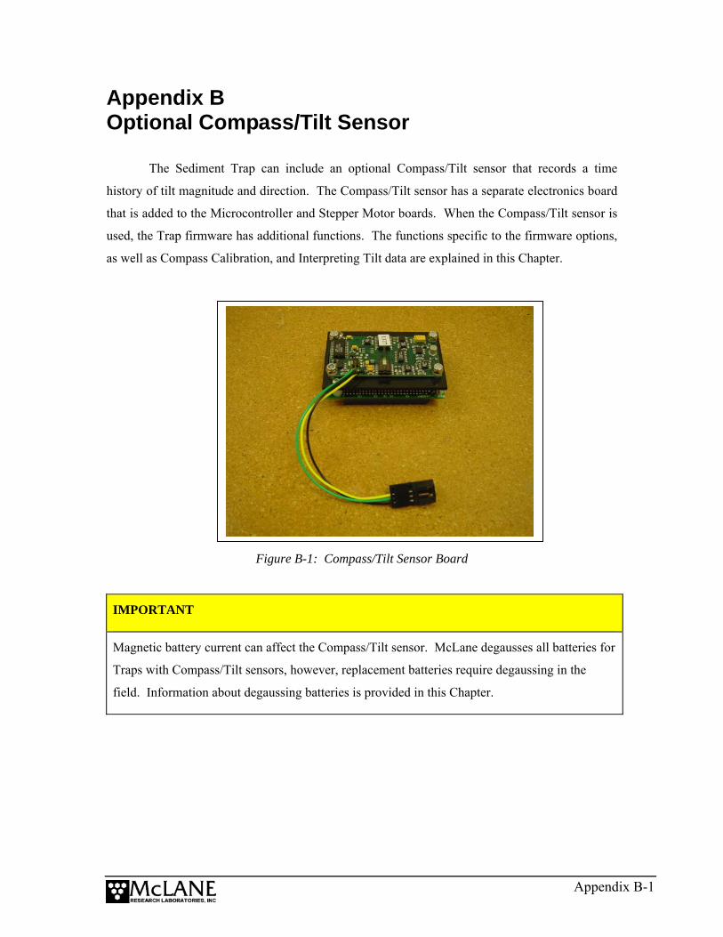
Appendix B Optional Compass/Tilt Sensor
The Sediment Trap can include an optional Compass/Tilt sensor that records a time
history of tilt magnitude and direction. The Compass/Tilt sensor has a separate electronics board
that is added to the Microcontroller and Stepper Motor boards. When the Compass/Tilt sensor is
used, the Trap firmware has additional functions. The functions specific to the firmware options,
as well as Compass Calibration, and Interpreting Tilt data are explained in this Chapter.
Figure B-1: Compass/Tilt Sensor Board
IMPORTANT
Magnetic battery current can affect the Compass/Tilt sensor. McLane degausses all batteries for
Traps with Compass/Tilt sensors, however, replacement batteries require degaussing in the
field. Information about degaussing batteries is provided in this Chapter.
Appendix B-1

Compass/Tilt Sensor Firmware Options If the Compass/Tilt sensor is installed, the Trap firmware user interface contains these
options:
• The Diagnostics display shows tilt magnitude.
• A prompt to enter the tilt sample interval displays when the deployment is initiated.
• The Offload Data option has a selection to display tilt data separately.
• EEPROM stores every 15th record from the tilt time history.
Each option is explained in detail below.
Diagnostics Display with Compass/Tilt Sensor
Selecting <2> Diagnostics displays a scrolling status that includes tilt magnitude in
degrees of tilt (ºT) and compass heading (ºH). The date and time, battery voltage, ambient
temperature, and rotator status are also displayed. In the Diagnostics display example shown
next, the system is initially tilted 11º from the vertical, towards the NNW, (~345º magnetic). The
system is then rotated and leveled, finishing with a 4º tilt to the NE, (~46º magnetic).
╔═════════════════════════════════╗ ║ Main Menu ║ ╚═════════════════════════════════╝
Thu Jan 1 02:15:47 1970 <1> Set Time <5> Create Schedule <2> Diagnostics <6> Deploy System <3> Fill Containers <7> Offload Data <4> Sleep <8> Contacting McLane Selection ? 2 05/24/01 13:08:57 21.0 Vb 21ºC 11ºT 347ºH aligned 05/24/01 13:08:59 21.0 Vb 21ºC 11ºT 345ºH aligned 05/24/01 13:09:00 21.0 Vb 21ºC 11ºT 345ºH aligned 05/24/01 13:09:01 21.0 Vb 21ºC 14ºT 344ºH aligned 05/24/01 13:09:02 21.0 Vb 21ºC 19ºT 11ºH aligned 05/24/01 13:09:04 21.0 Vb 21ºC 9ºT 26ºH aligned 05/24/01 13:09:05 21.0 Vb 21ºC 7ºT 36ºH aligned 05/24/01 13:09:06 21.0 Vb 21ºC 4ºT 42ºH aligned 05/24/01 13:09:07 21.0 Vb 21ºC 4ºT 46ºH aligned
Figure B-2: Diagnostics with Compass/Tilt Sensor display
Appendix B-2

Setting Tilt Data Frequency When <6> Deploy System is selected, a prompt displays to enter the time interval (in
minutes) for recording tilt data.
╔═════════════════════════════════╗ ║ Main Menu ║ ╚═════════════════════════════════╝
Thu Jan 1 02:15:47 1970 <1> Set Time <5> Create Schedule <2> Diagnostics <6> Deploy System <3> Fill Containers <7> Offload Data <4> Sleep <8> Contacting McLane
Selection ? 6 Enter tilt sample interval [minutes] (4 to 1440) ? 10
Figure B-3: Tilt Sample Interval display
NOTE
Recording Compass/Tilt data contributes to battery drain. Setting the tilt recording interval less
frequently (such as only when each sample event occurs) will conserve the battery.
Offloading Data with the Compass/Tilt Installed
When <7> Offload Data is selected, all data or specific data (an event summary or tilt
readings) can be displayed. Compass/Tilt data is also stored in EEPROM.
NOTE
EEPROM stores only every 15th tilt time history record to maximize storage space.
Appendix B-3
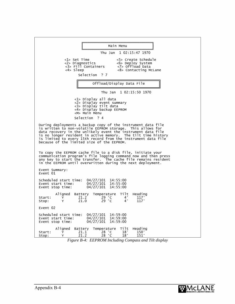
╔═════════════════════════════════╗ ║ Main Menu ║ ╚═════════════════════════════════╝
Thu Jan 1 02:15:47 1970 <1> Set Time <5> Create Schedule <2> Diagnostics <6> Deploy System <3> Fill Containers <7> Offload Data <4> Sleep <8> Contacting McLane
Selection ? 7
Thu Jan 1 02:15:50 1970
<1> Display all data <2> Display event summary <3> Display tilt data <4> Display backup EEPROM <M> Main Menu
Selection ? 4 During deployments a backup copy of the instrument data file is written to non-volatile EEPROM storage. This allows for data recovery in the unlikely event the instrument data file is no longer resident in active memory. The tilt time history is limited to every 15th record from the instrument data file because of the limited size of the EEPROM. To copy the EEPROM cache file to a disk file, initiate your communication program's file logging command now and then press any key to start the transfer. The cache file remains resident in the EEPROM until overwritten during the next deployment. Event Summary: Event 01 Scheduled start time: 04/27/101 14:55:00 Event start time: 04/27/101 14:55:00 Event stop time: 04/27/101 14:55:00 Aligned Battery Temperature Tilt Heading Start: Y 21.2 29 °C 4° 117° Stop: Y 21.0 29 °C 4° 117° Event 02 Scheduled start time: 04/27/101 14:59:00 Event start time: 04/27/101 14:59:00 Event stop time: 04/27/101 14:59:00 Aligned Battery Temperature Tilt Heading Start: Y 21.1 28 °C 18° 150° Stop: Y 21.2 28 °C 18° 151°
Offload/Display Data File
Figure B-4: EEPROM Including Compass and Tilt display
Appendix B-4
Calibrating the Compass McLane performs a “hard iron” calibration (with degaussed batteries) for each Trap that
includes a Compass/Tilt sensor. This procedure removes the effects of weak local magnetic
fields that rotate with the instrument. Re-calibration is generally not required if the “C” cells in
the main battery pack and the 9V backup battery are degaussed before use.
NOTE
McLane can assist with calibration in the field if necessary. Software tools are provided on a
CD-ROM in the Toolkit and the required interface is built into the firmware and electronics.
IMPORTANT
A stable, flat platform free of strong magnetic fields is essential for re-calibrating the compass.
Tilt Data and Alignment The compass collects data on tilt magnitude and direction, displayed and recorded in
degrees from the vertical. Tilt direction, the heading toward which the top of the trap is tipped, is
displayed and recorded in degrees measured clockwise from north: north = 0º, east = 90º, south =
180º, and west = 270º.
During deployment scheduling, the operator may set the frequency (in minutes) of tilt
data acquisition. The tilt and tilt heading are also recorded at the beginning and end of each
rotator movement. A time history of tilt and tilt heading during the periods between rotator
movements is also recorded. Non-volatile memory stores all of the data associated with rotator
movements and every 15th tilt value from the time history (limited by EEPROM storage space).
NOTE
Tilt accuracy is approximately ±1º (heading accuracy is 5º-10º, limited by the compass which
can be strongly affected by local magnetic fields).
Appendix B-5

Tilt Alignment The Compass/Tilt sensor must be level within the controller housing. If the end cap is
removed from the controller housing, reinstall as shown in Figure B-5, by sliding the end cap into
the controller housing with bulkhead connectors parallel.
Figure B-5: Correct End Cap Orientation in Controller Housing
Figure B-6: Incorrect End Cap Orientation in Controller Housing
Appendix B-6
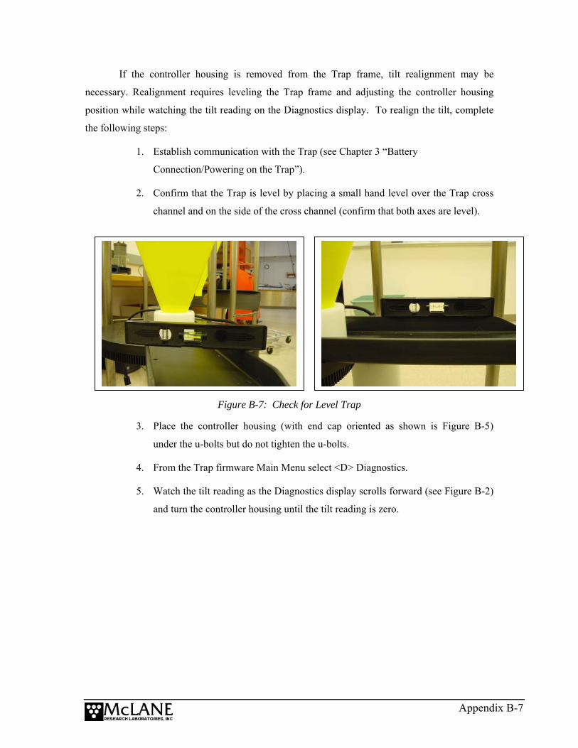
If the controller housing is removed from the Trap frame, tilt realignment may be
necessary. Realignment requires leveling the Trap frame and adjusting the controller housing
position while watching the tilt reading on the Diagnostics display. To realign the tilt, complete
the following steps:
1. Establish communication with the Trap (see Chapter 3 “Battery
Connection/Powering on the Trap”).
2. Confirm that the Trap is level by placing a small hand level over the Trap cross
channel and on the side of the cross channel (confirm that both axes are level).
Figure B-7: Check for Level Trap
3. Place the controller housing (with end cap oriented as shown is Figure B-5)
under the u-bolts but do not tighten the u-bolts.
4. From the Trap firmware Main Menu select <D> Diagnostics.
5. Watch the tilt reading as the Diagnostics display scrolls forward (see Figure B-2)
and turn the controller housing until the tilt reading is zero.
Appendix B-7
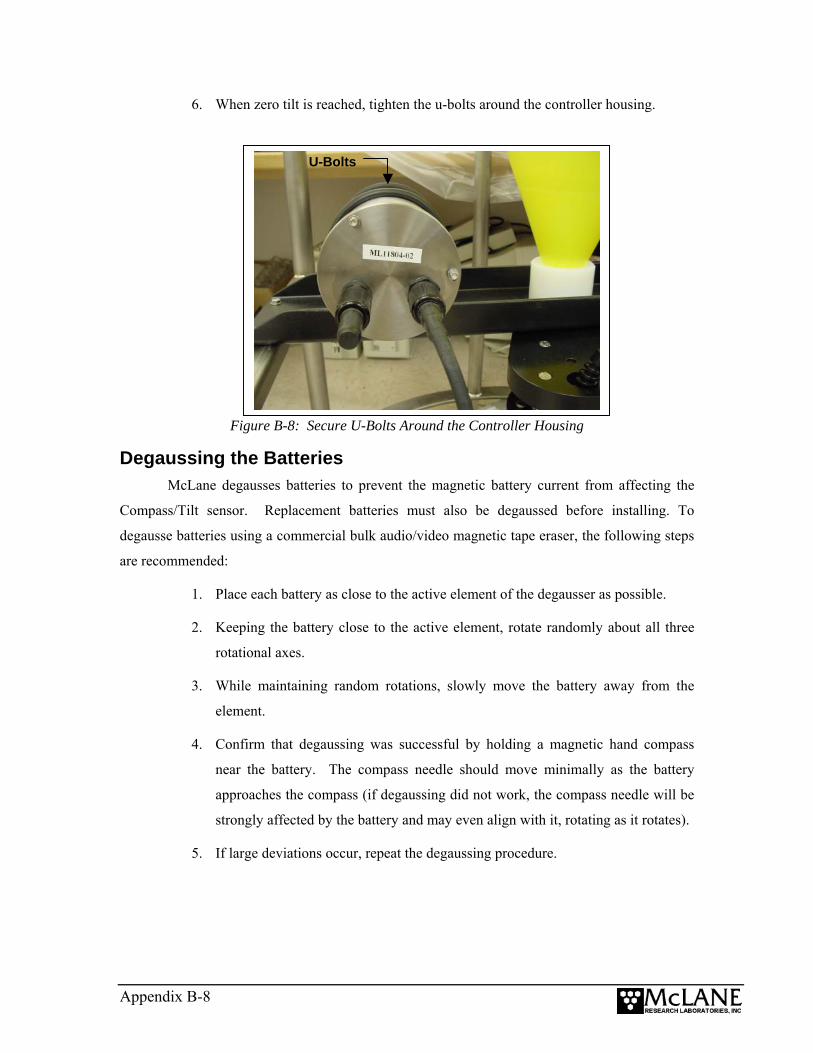
6. When zero tilt is reached, tighten the u-bolts around the controller housing.
Figure B-8: Secure U-Bolts Around the Controller Housing
U-Bolts
Degaussing the Batteries McLane degausses batteries to prevent the magnetic battery current from affecting the
Compass/Tilt sensor. Replacement batteries must also be degaussed before installing. To
degausse batteries using a commercial bulk audio/video magnetic tape eraser, the following steps
are recommended:
1. Place each battery as close to the active element of the degausser as possible.
2. Keeping the battery close to the active element, rotate randomly about all three
rotational axes.
3. While maintaining random rotations, slowly move the battery away from the
element.
4. Confirm that degaussing was successful by holding a magnetic hand compass
near the battery. The compass needle should move minimally as the battery
approaches the compass (if degaussing did not work, the compass needle will be
strongly affected by the battery and may even align with it, rotating as it rotates).
5. If large deviations occur, repeat the degaussing procedure.
Appendix B-8

Battery Duration when using Compass/Tilt Sensor The Compass/Tilt sensor affects battery life (the 14 alkaline “C” cells in the battery pack
deliver approximately 5,000 mAh). Use the information in this section to estimate battery
duration for deployments when the Compass/Tilt sensor is used.
NOTE
Tilt reading frequency can be lowered to conserve battery life (see Figure B-3).
Instrument Current Consumption Controller unit 3.0 mA
Controller unit in low power mode 0.30 mA
Move bottle 1.3 mAh
Tilt reading 21.0 µAh
An example battery duration estimate with the Tilt/Compass set for readings at 30 minute
intervals is shown next.
Appendix B-9

Example Deployment Battery Estimate Pre-deployment Controller (1 hour) 1 h x 3.0 mA = 3.0 mAh
Move bottle (22 bottles) 22 x 1.3mAh = 28.6 mAh
Subtotal = 31.6 mAh
Deployment
Controller (12 months) 8760 h x 0.30 mA = 2628 mAh
Move bottle (22 bottles) 22 x 1.3 mAh = 28.6 mAh
Tilt readings (30 minute intervals) 17520 x 21.0 µAh = 368 mAh
Subtotal = 3025 mAh
Recovery
Controller (1 hour) 1 h x 3.0 mA = 3.0 mAh
Subtotal = 3.0 mAh
Total Current Consumption Total = 3,060 mAh
This example shows that the estimated battery drain for the proposed deployment totals
3,060 mAh, and will not exceed the 5,000 mAh capacity of the battery pack.
Appendix B-10
Appendix C Rotator Assembly Variseals® and Bearings
Rinsing before and after each deployment keeps the rotator assembly in optimal working
condition for many deployments and/or years. The plastic ball bearings inside the gear plate
assembly and the Variseals® in the gear ring holes are durable and long-lasting. This Appendix
contains steps that can be used (only if necessary) to replace these parts.
IMPORTANT
Contact McLane before replacing Variseals® or ball bearings. The rotator assembly must be
handled with care to prevent damage.
Overview Replacing Varisals® and/or ball bearings is a multi-step process that consists of the
following:
• Step 1 − Remove Components From the Frame
• Step 2 − Clean and Replace Variseals®
• Step 3 − Clean and Replace Ball Bearings
• Step 4 − Reassemble Rotator Plates
• Step 5 − Perform a Leak Test
• Step 6 − Reinstall Components Onto the Frame
NOTE
Spare ball bearings are included in the Sediment Trap Toolkit and Variseals® can be obtained
from McLane.
Appendix C-1
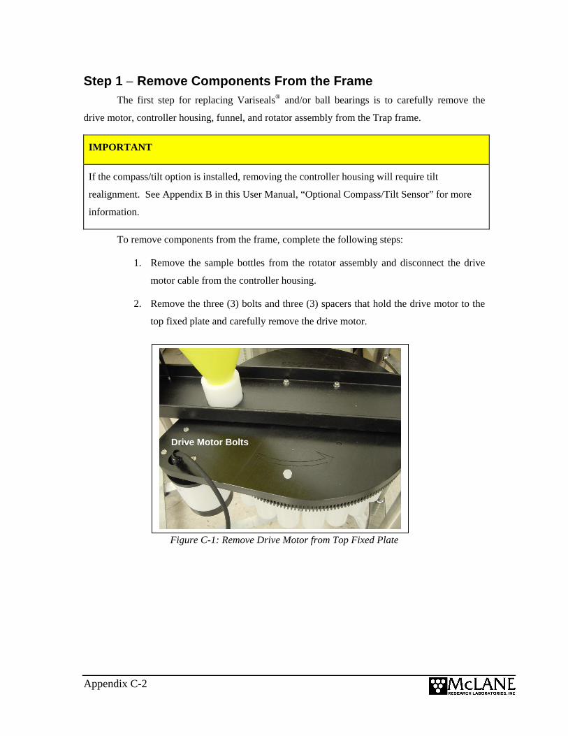
Step 1 − Remove Components From the Frame The first step for replacing Variseals® and/or ball bearings is to carefully remove the
drive motor, controller housing, funnel, and rotator assembly from the Trap frame.
IMPORTANT
If the compass/tilt option is installed, removing the controller housing will require tilt
realignment. See Appendix B in this User Manual, “Optional Compass/Tilt Sensor” for more
information.
To remove components from the frame, complete the following steps:
1. Remove the sample bottles from the rotator assembly and disconnect the drive
motor cable from the controller housing.
2. Remove the three (3) bolts and three (3) spacers that hold the drive motor to the
top fixed plate and carefully remove the drive motor.
Figure C-1: Remove Drive Motor from Top Fixed Plate
Drive Motor Bolts
Appendix C-2
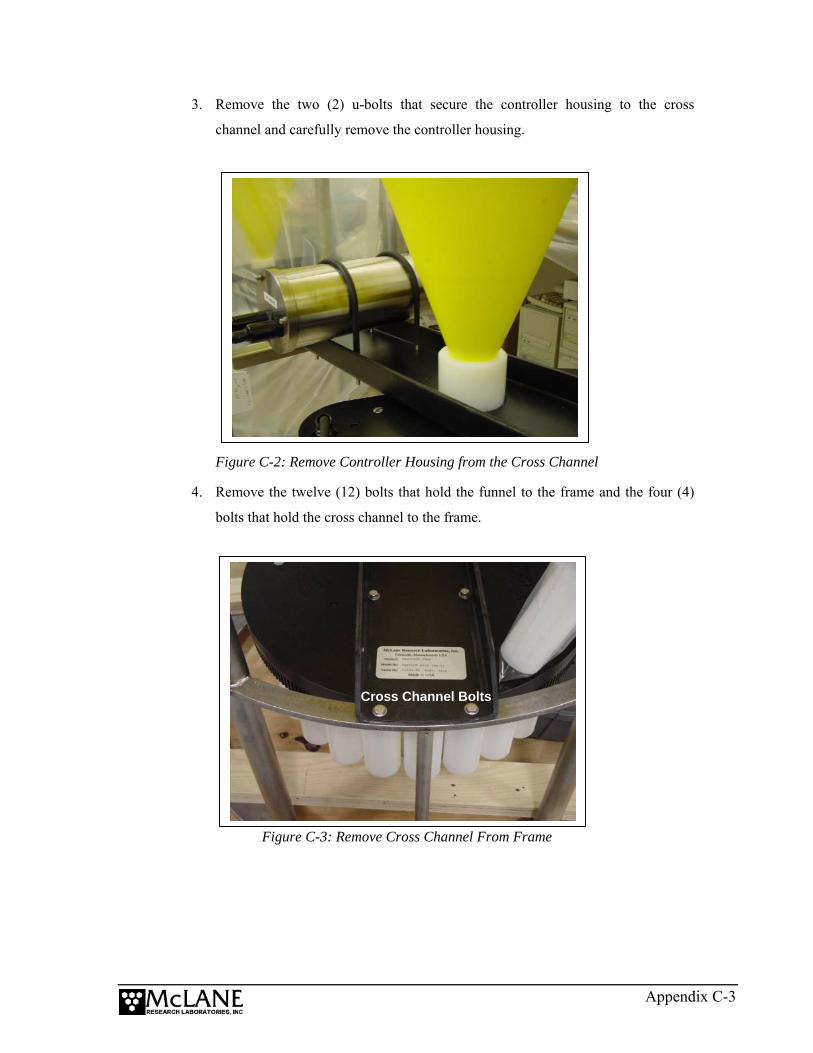
3. Remove the two (2) u-bolts that secure the controller housing to the cross
channel and carefully remove the controller housing.
Figure C-2: Remove Controller Housing from the Cross Channel
4. Remove the twelve (12) bolts that hold the funnel to the frame and the four (4)
bolts that hold the cross channel to the frame.
Figure C-3: Remove Cross Channel From Frame
Cross Channel Bolts
Appendix C-3
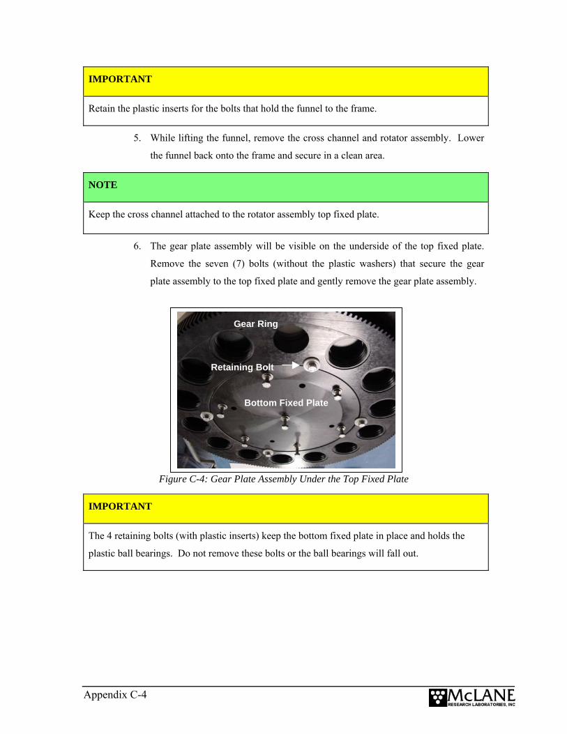
IMPORTANT
Retain the plastic inserts for the bolts that hold the funnel to the frame.
5. While lifting the funnel, remove the cross channel and rotator assembly. Lower
the funnel back onto the frame and secure in a clean area.
NOTE
Keep the cross channel attached to the rotator assembly top fixed plate.
6. The gear plate assembly will be visible on the underside of the top fixed plate.
Remove the seven (7) bolts (without the plastic washers) that secure the gear
plate assembly to the top fixed plate and gently remove the gear plate assembly.
Figure C-4: Gear Plate Assembly Under the Top Fixed Plate
Retaining Bolt
Gear Ring
Bottom Fixed Plate
IMPORTANT
The 4 retaining bolts (with plastic inserts) keep the bottom fixed plate in place and holds the
plastic ball bearings. Do not remove these bolts or the ball bearings will fall out.
Appendix C-4
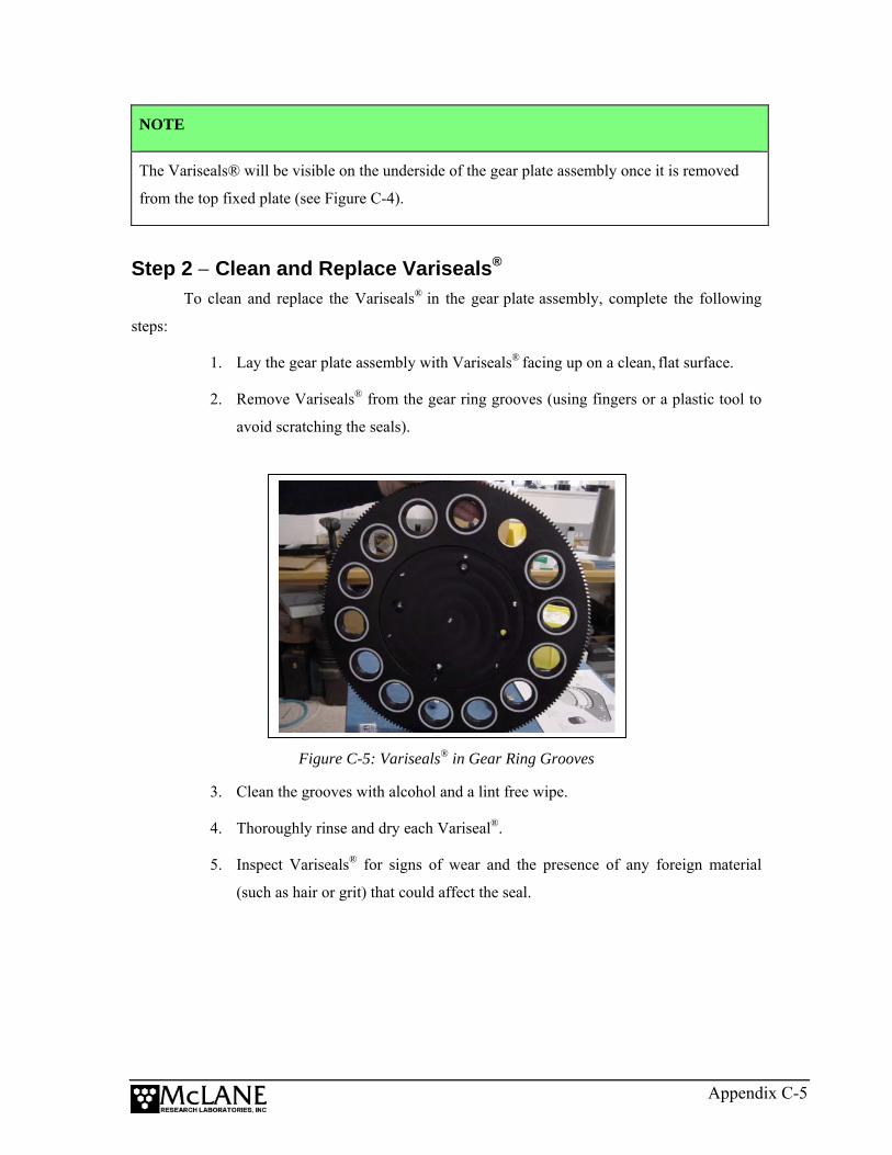
NOTE
The Variseals® will be visible on the underside of the gear plate assembly once it is removed
from the top fixed plate (see Figure C-4).
Step 2 − Clean and Replace Variseals®
To clean and replace the Variseals® in the gear plate assembly, complete the following
steps:
1. Lay the gear plate assembly with Variseals® facing up on a clean, flat surface.
2. Remove Variseals® from the gear ring grooves (using fingers or a plastic tool to
avoid scratching the seals).
Figure C-5: Variseals® in Gear Ring Grooves
3. Clean the grooves with alcohol and a lint free wipe.
4. Thoroughly rinse and dry each Variseal®.
5. Inspect Variseals® for signs of wear and the presence of any foreign material
(such as hair or grit) that could affect the seal.
Appendix C-5
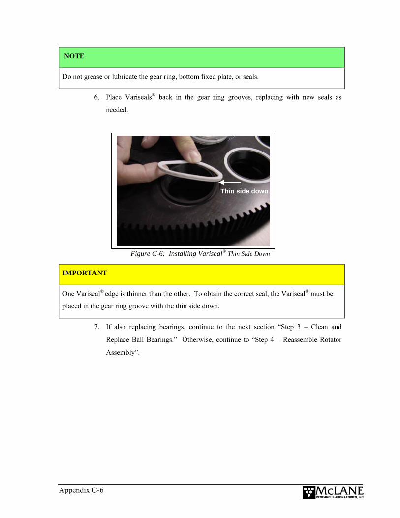
NOTE
Do not grease or lubricate the gear ring, bottom fixed plate, or seals.
6. Place Variseals® back in the gear ring grooves, replacing with new seals as
needed.
Figure C-6: Installing Variseal® Thin Side Down
Thin side down
IMPORTANT
One Variseal® edge is thinner than the other. To obtain the correct seal, the Variseal® must be
placed in the gear ring groove with the thin side down.
7. If also replacing bearings, continue to the next section “Step 3 – Clean and
Replace Ball Bearings.” Otherwise, continue to “Step 4 − Reassemble Rotator
Assembly”.
Appendix C-6

Step 3 − Clean and Replace Ball Bearings Complete the steps in this section to clean and replace ball bearings.
NOTE
Complete Step 1 “Remove Components from the Frame” before beginning this step.
1. If not already done, the gear plate assembly should be removed from the top
fixed plate (see Figure C-6).
2. Place the gear plate assembly with Variseals® facing up on a clean, flat surface
and remove the bottom fixed plate.
3. Remove the four (4) retaining bolts (with plastic washers) that secure the bottom
fixed plate to the gear ring and remove the bottom fixed plate.
Figure C-7: Removing Bottom Fixed Plate
Bottom Fixed Plate
4. Remove the bearings and rinse and dry thoroughly to remove salt or other foreign
matter.
5. Clean the bearing groove with alcohol and a lint free wipe.
6. Inspect bearings and confirm that there are no chips or other damage. Damaged
bearings should be replaced with spares from the Toolkit.
7. Fill the bearing groove with bearings.
Appendix C-7
NOTE
The bearing groove for the 21 cup Trap holds approximately 99 bearings (approximately 78
bearings for the 13 cup Trap). A fast method for filling the groove in either size Trap is to add
bearings until no more will fit and then remove four (4) bearings.
8. Reinstall the bottom fixed plate and tighten the 4 retaining bolts.
9. Tighten the 7 securing bolts only until the lock washers become flat.
10. Proceed to “Step 4 − Reassemble Rotator Assembly”.
Step 4 − Reassemble Rotator Assembly 1. Rinse the top fixed plate and gear plate assembly with fresh water.
IMPORTANT
Do not clean the plates with an abrasive cleaner. The surface of the top fixed plate must remain
smooth to correctly seal.
2. Reattach the gear plate assembly to the top fixed plate by aligning the center
holes and tightening the bolts (position the bolts in the threaded holes and tighten
only until the lock washer is flat).
3. Manually rotate the gear plate assembly so that the unthreaded alignment hole
matches up with the hole in the top fixed plate.
Appendix C-8

Step 5 − Perform a Leak Test After parts are replaced and the rotator is reassembled, a leak test should be performed to
ensure that the rotator assembly is properly sealed. To perform a leak test, complete the steps
shown next.
1. Confirm that the rotator assembly fill plug is in place before beginning the leak
test.
2. Place the rotator assembly in a sink or wet area.
Figure C-8: Fill Plug on Rotator Assembly
Appendix C-9
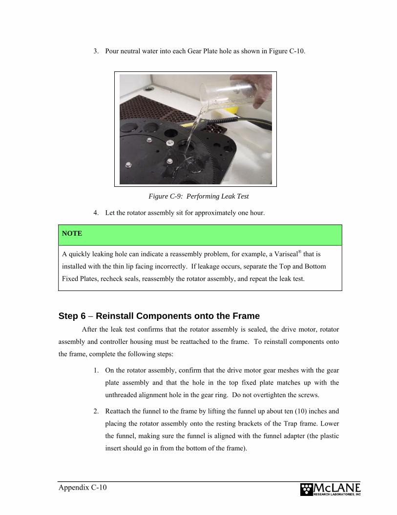
3. Pour neutral water into each Gear Plate hole as shown in Figure C-10.
Figure C-9: Performing Leak Test
4. Let the rotator assembly sit for approximately one hour.
NOTE
A quickly leaking hole can indicate a reassembly problem, for example, a Variseal® that is
installed with the thin lip facing incorrectly. If leakage occurs, separate the Top and Bottom
Fixed Plates, recheck seals, reassembly the rotator assembly, and repeat the leak test.
Step 6 − Reinstall Components onto the Frame After the leak test confirms that the rotator assembly is sealed, the drive motor, rotator
assembly and controller housing must be reattached to the frame. To reinstall components onto
the frame, complete the following steps:
1. On the rotator assembly, confirm that the drive motor gear meshes with the gear
plate assembly and that the hole in the top fixed plate matches up with the
unthreaded alignment hole in the gear ring. Do not overtighten the screws.
2. Reattach the funnel to the frame by lifting the funnel up about ten (10) inches and
placing the rotator assembly onto the resting brackets of the Trap frame. Lower
the funnel, making sure the funnel is aligned with the funnel adapter (the plastic
insert should go in from the bottom of the frame).
Appendix C-10
3. Secure the funnel to the Trap frame with the twelve (12) sets of nuts and bolts.
When attaching the funnel, confirm that the plastic inserts are correctly placed in
the holes on the frame.
IMPORTANT
The mounting holes in the funnel are not spaced symmetrically. The funnel lip and the frame
were marked with black ink prior to shipment to help align the bolt holes during re-assembly.
4. Secure the four (4) sets of nuts and bolts to reattach the cross channel to the
frame.
5. Carefully re-install the drive motor by reattaching the three (3) bolts and three (3)
spacers that hold the drive motor to the rotator assembly top fixed plate.
6. Carefully reattach the controller housing to the cross channel by re-securing the
two (2) u-bolts.
IMPORTANT
Re-check gear ring alignment prior to deployment.
Appendix C-11

Notes
Appendix C-12
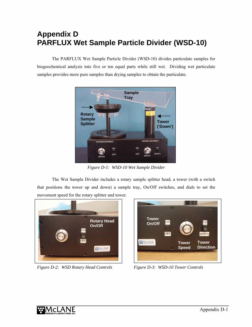
Appendix D PARFLUX Wet Sample Particle Divider (WSD-10)
The PARFLUX Wet Sample Particle Divider (WSD-10) divides particulate samples for
biogeochemical analysis into five or ten equal parts while still wet. Dividing wet particulate
samples provides more pure samples than drying samples to obtain the particulate.
Tower (‘Down’)
Rotary Sample Splitter
Sample Tray
Figure D-1: WSD-10 Wet Sample Divider
The Wet Sample Divider includes a rotary sample splitter head, a tower (with a switch
that positions the tower up and down) a sample tray, On/Off switches, and dials to set the
movement speed for the rotary splitter and tower.
Tower Direction
Tower Speed
Tower On/Off
Rotary Head Speed
Rotary Head On/Off
Figure D-2: WSD Rotary Head Controls Figure D-3: WSD-10 Tower Controls
Appendix D-1
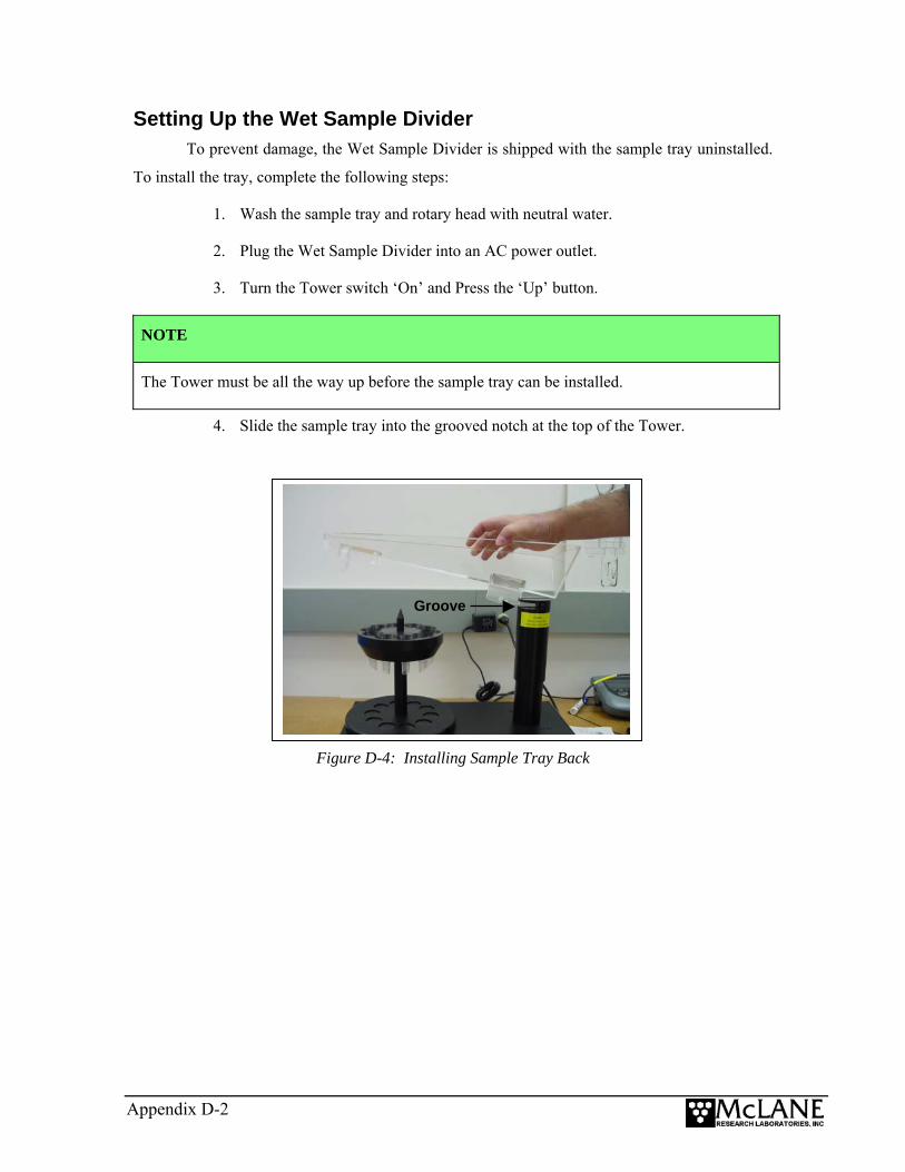
Setting Up the Wet Sample Divider To prevent damage, the Wet Sample Divider is shipped with the sample tray uninstalled.
To install the tray, complete the following steps:
1. Wash the sample tray and rotary head with neutral water.
2. Plug the Wet Sample Divider into an AC power outlet.
3. Turn the Tower switch ‘On’ and Press the ‘Up’ button.
NOTE
The Tower must be all the way up before the sample tray can be installed.
4. Slide the sample tray into the grooved notch at the top of the Tower.
Figure D-4: Installing Sample Tray Back
Groove
Appendix D-2
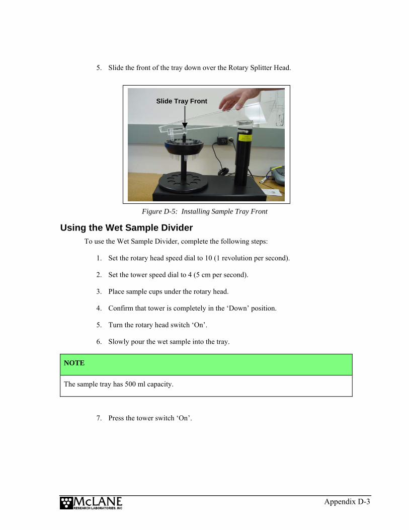
5. Slide the front of the tray down over the Rotary Splitter Head.
Figure D-5: Installing Sample Tray Front
Slide Tray Front
Using the Wet Sample Divider To use the Wet Sample Divider, complete the following steps:
1. Set the rotary head speed dial to 10 (1 revolution per second).
2. Set the tower speed dial to 4 (5 cm per second).
3. Place sample cups under the rotary head.
4. Confirm that tower is completely in the ‘Down’ position.
5. Turn the rotary head switch ‘On’.
6. Slowly pour the wet sample into the tray.
NOTE
The sample tray has 500 ml capacity.
7. Press the tower switch ‘On’.
Appendix D-3

8. When the sample begins to drain from the tray, use a squirt bottle to pour a
constant stream of neutral water into the tray and move the sample down into the
sample bottles.
9. After the tower stops in the upward position, rinse the sides of the tray with water
from the squirt bottle.
10. Press the rotary head switch ‘Off’.
11. Remove the sample tray.
12. Rinse the side walls of the rotary head.
WSD-10 Specifications The table shown next lists the Wet Sample Divider specifications.
Dimensions Length 41 cm Width 22 cm
Height 45 cm
Weight 8 kg
Materials Construction materials Acetal & acrylic
Sample containers 40 ml vials or 250 ml bottles
Power Required 15 VDC
Features Number of aliquots 5 or 10 Sample tray volume 500 ml Maximum size of particles <10 mm
Deviation between aliquots < 5.0%
Approx. time for sample division 10 minutes
Maximum divider speed 1 rev/sec
Maximum tower speed 2.3 mm/sec
Supplies Standard supplies 100 Glass vials with caps AC power supply
Extra sample containers
Appendix D-4
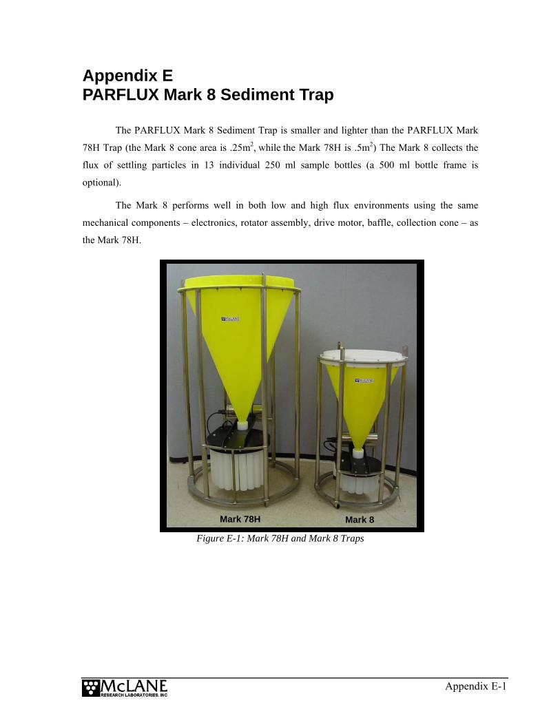
Appendix E PARFLUX Mark 8 Sediment Trap
The PARFLUX Mark 8 Sediment Trap is smaller and lighter than the PARFLUX Mark
78H Trap (the Mark 8 cone area is .25m2, while the Mark 78H is .5m2) The Mark 8 collects the
flux of settling particles in 13 individual 250 ml sample bottles (a 500 ml bottle frame is
optional).
The Mark 8 performs well in both low and high flux environments using the same
mechanical components – electronics, rotator assembly, drive motor, baffle, collection cone – as
the Mark 78H.
Figure E-1: Mark 78H and Mark 8 Traps
Mark 8 Mark 78H
Appendix E-1

Appendix E-2
Mark 8 Sediment Trap Specifications Mark 8 Sediment Trap specifications are listed in the table below.
Dimensions Height 116 cm Diameter 66 cm Vertical Surface Area 0.66 m2
Weight (w/out bridle) In air, sample bottles empty 38.8 kg In air, sample bottles full 42 kg
In water 18 kg
Aperture/Funnel Aperture Area 0.25 m2 Aperture Diameter 53.7 cm Baffle Material Polycarbonate Baffle Wall Thickness 1.0 mm Number of Baffle Cells Approx. 368 Baffle Cell Diameter 2.5 cm Aspect Ratio of Cell (h/d) 2:5 Included Cone Angle 41° Internal Coating (liner) Natural Polyethylene
Rotary Assembly Standard Bottle Volume 250 (500 ml optonal) Driving Motor Type Electronic stepper motor Drive Train Direct Gear Train
Battery Primary battery 14 “C” size alkaline cells
Memory backup 9V alkaline battery
Frame Material Titanium, Ti-45 G-2 Structure Weldment Bridle Configuration 3 and 3 in-line Bridle eyes 1.29 cm insulated
Operation Conditions Depth 10,000 m (optional aluminum housing rated to 6,000 m)
Minimum deployment period One minute per bottle
Max. continuous deployment 18 mos.
Temperature
(electronics tested to –10°C)
–2° to +50°C