measuring electronic latencies in minos with auxiliary detector
TRANSCRIPT

Measuring electronic latencies in MINOS with Auxiliary Detector
Son V. Cao University of Texas at Aus@n
(on behalf of the MINOS collabora@on) June 14th 2012
MINOS overview TOF principle AD setup Measurement Summary
FNAL2012 New Perspec@ves

2
MINOS overview TOF principle AD setup Measurement Summary
Main Injector Neutrino Oscilla@on Search (MINOS)
734 km
Near det. 1.0 kton
Far det. 5.4 kton
ü High intensity muon neutrino beam produced at Fermilab ü Two detectors: reduce systema@c errors, magne@zed to dis@nguish interac@ons
ü Near Detector to measure ini@al beam composi@on, predict no-‐oscilla@on spectrum at Far Detector ü Long baseline (734km) Time of
Flight (TOF) (1st measurement in 2007)
We revisit TOF with more staDsDcs and refined understanding of system
⌫µ and ⌫̄µ

3
MINOS overview TOF principle AD setup Measurement Summary
v =d21
(t2 � t1)
Basic principle:
Real measurement:
P1(t1) P2(t2)
Distance d21
t1 t2
Find to minimize the likelihood between and
In 2007, used 473 FD events:
2. Time of Flight (TOF) principle
�t21P2(t2)P1(t1)
Need to understand the Dming system beNer!!!
Time shiP by TOFv
Baseline à TOFc
�t = �126± 32(stat.)± 64(syst.) ns (68% C.L. )
(v/c� 1) = 5.1± 2.9⇥ 10�5(68% C.L.)
Source of latency Uncertainty 2007
ND electronic latencies 32ns
FD electronic latencies 3ns
F/N detector rela@ve latencies 9ns

4
3. Auxiliary Detector (AD) MINOS overview TOF principle AD setup Measurement Summary
Auxiliary Detector at the back end of Near Detector
Auxiliary Detector in the middle of two Super-‐Modules at Far Detector
⌫ beam
Auxiliary Detector Dmestamps muon, resultant parDcle of neutrino interacDon, and matches with events recorded in real detector

ü Readout system has complicated latency, not easy to measure
ü Two readout systems of MINOS detector are not the same systema@c error
ü Using two iden@cal readout systems, Auxiliary Detector (AD), can cancel out this error
5
Goal: measure the latencies and miDgate the systemaDc error using a simple auxiliary system
Near Far
UTC Dme
⌫ beam
AD AD
3. AD setup: mo@va@on MINOS overview TOF principle AD setup Measurement Summary

5. Event @mestamp with AD 3. AD setup: event @mestamp MINOS overview TOF principle AD setup Measurement Summary
6
ü Passage of muon produces blue scin@lla@on light
ü Wavelength-‐shi`ing fiber absorbs and shi`s scin@lla@on light
ü Signals are mul@plied by photomul@plier (PMT) and used as “STOP” signal
ü Timestamp “STOP” signal with a “START” reference signal in each detector
RelaDve electronic latency between ADs and real detectors is calculated by event matching
ScinDllator paddle
PMT

7
Timing diagram
Timing system overview MINOS overview TOF principle AD setup Measurement Summary
Beam structure ( 53MHz unit)
~10 us
ü Accelerator generates signal, named $74, tell kicker magnet to prepare extrac@ng the proton beam
ü Each spill lasts about 10us ü At ND, Front-‐End boards start
window, labeled SGATE, to collect data
ü At FD, another window, labeled
SS Window, is opened to capture data at the @me spill arrives
8
5. Matching AD and ND
Ending edge
Matching AD and ND time distribution (ns) 11100 11150 11200 11250
Num
ber o
f eve
nts/
2ns
0
500
1000
1500
2000
Auxiliary Detector
Near Detector
MINOS Preliminary
Dip Dip
Matching AD and ND time distribution (ns) 4650 4700 4750 4800
Num
ber o
f eve
nts/
2ns
0
1000
2000Auxiliary Detector
Near Detector
MINOS Preliminary
Matching AD and ND time distribution (ns) 1450 1500 1550 1600
Num
ber o
f eve
nts/
2ns
0
1000
2000
3000
Auxiliary Detector
Near Detector
MINOS Preliminary
Leading edge Ending edge Dip
Time relative to spill (18.83ns bins)200 400 600
Num
ber o
f eve
nts
/ 18.
83ns
0
100
200
300
400MINOS Preliminary
MINOS overview TOF principle AD setup Measurement Summary
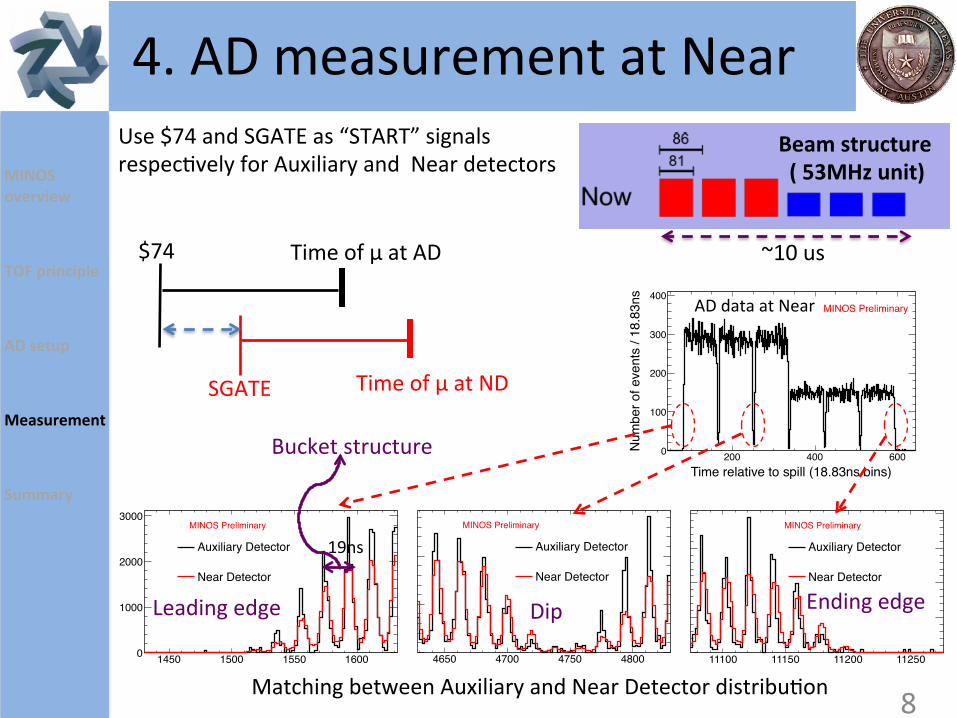
Matching between Auxiliary and Near Detector distribu@on
4. AD measurement at Near Beam structure ( 53MHz unit)
~10 us $74
SGATE
Time of μ at AD
Time of μ at ND
Use $74 and SGATE as “START” signals respec@vely for Auxiliary and Near detectors
8
AD data at Near
19ns
Bucket structure

9
Offset between SGATE and $74 at AD(ns)212850 212900 212950
Log
likeh
ood
0
2000
4000
6000
8000
MINOS PreliminaryDistribu@on comparison
MINOS overview TOF principle AD setup Measurement Summary
4. AD measurement at Near
19ns
ü Calculate likelihood of AD-‐ND distribu@on comparison as a func@on of SGATE-‐$74 “offset”
ü Likelihood reflects very well the
bucket structure but the true peak is not clear.
ü SGATE-‐$74 @me interval is not true
offset. SGATE is programmably lined up with 53.1MHz clock @ck.
ü The direct measurement of SGATE-‐$74 @me interval also shows two peaks separated by 19ns.
SGATE -‐ $74 @me interval
Num
ber o
f events

10
Offset between SGATE and $74 at AD(ns)212850 212900 212950
Log
likeh
ood
0
2000
4000
6000
8000
MINOS Preliminary
Entries 5121
Mean 212908.120
RMS 16.877
Offset between SGATE and $74 at AD (ns)212850 212900 212950 213000
Num
ber o
f eve
nts
/ 2ns
0
50
100
150 Entries 5121
Mean 212908.120
RMS 16.877
MINOS Preliminary
Distribu@on comparison
MINOS overview TOF principle AD setup Measurement Summary
4. AD measurement at Near
19ns
Event-‐by-‐event matching
No latency included
ND -‐ AD latencies = 36 +/-‐ 4ns
ü AD is synchronized to ND DAQ, permined to match in event-‐by-‐event basis.
ü These peaks agrees with those from
distribu@on comparison
ü “Offset” measured by AD includes the electronic latencies of AD and ND
ü Calculate AD-‐ND electronic latency by
comparing with @me interval from direct measurement (mean of the peak is used)
AD-‐ND latencies included
4ns

11
5. Matching AD and ND MINOS overview TOF principle AD setup Measurement Summary
4. AD measurement at Far
FD -‐ AD latencies = 12 +/-‐ 2ns
Entries 81Mean 98.602RMS 8.083
/ ndf 2r 57.218 / 47Constant 1.028± 23.342 Mean 0.102± 96.579 Sigma 0.123± 2.145
Offset between AD and FD (ns)60 80 100 120 140
Num
ber o
f eve
nts
/ 2ns
0
10
20
Entries 81Mean 98.602RMS 8.083
/ ndf 2r 57.218 / 47Constant 1.028± 23.342 Mean 0.102± 96.579 Sigma 0.123± 2.145
MINOS Preliminary
ü Use cosmic ray events for matching
ü Use PPS signals from Cs Clock and GPS as “START” signals respec@vely for Auxiliary and Far detectors
Cs PPS
GPS PPS
Time of μ at AD
Time of μ at FD
Monitored by Agilent 53230A

ü The ADs are necessary for mi@ga@ng the electronic readout latencies
ü The ADs has already installed and first results are used for TOF retrospec@ve analysis in 2012
ü The AD will be used in the next phase of Time Of Flight measurement
12
Summary Summary
Source of latency Uncertainty 2007 Uncertainty 2012
ND electronic latencies 32ns 4ns
FD electronic latencies 3ns 2ns
F/N detector rela@ve latencies 9ns 1ns
MINOS overview TOF principle AD setup Measurement Summary
Full Spill approach: TOFv – TOFc = -‐18 ± 11 (stat.) ± 29 (syst.) ns Wrapped Spill approach: TOFv – TOFc = -‐11 ± 11 (stat.) ± 29 (syst.) ns

13
5. 4. MINOS plans
13
Backup: Fit at peaks MINOS overview TOF principle AD setup Measurement Summary
Entries 5121Mean 212908.120RMS 16.877
/ ndf 2r 28.844 / 13Constant 7.354± 155.895 Mean 0.159± 212892.656 Sigma 0.105± 3.404
Offset between SGATE and $74 at AD (ns)212850 212900 212950 213000
Num
ber o
f eve
nts
/ 2ns
0
50
100
150Entries 5121Mean 212908.120RMS 16.877
/ ndf 2r 28.844 / 13Constant 7.354± 155.895 Mean 0.159± 212892.656 Sigma 0.105± 3.404
MINOS Preliminary
Entries 5121Mean 212908.120RMS 16.877
/ ndf 2r 125.557 / 12Constant 7.629± 141.745 Mean 0.198± 212911.391 Sigma 0.267± 5.596
Offset between SGATE and $74 at AD (ns)212850 212900 212950 213000
Num
ber o
f eve
nts
/ 2ns
0
50
100
150Entries 5121Mean 212908.120RMS 16.877
/ ndf 2r 125.557 / 12Constant 7.629± 141.745 Mean 0.198± 212911.391 Sigma 0.267± 5.596
MINOS Preliminary

14
5. 4. MINOS plans
2007 Analysis
Phase I (6 months)
Phase II (9-‐12 months)
Phase III (2013 and on MINOS+ era)
Re-‐analysis exis@ng data, reduce dominant systema@c errors
Hardware improvement
More hardware improvement , update beam energy
64 ns 18-‐33 ns 11-‐18 ns 2-‐7 ns
• (A) Resurvey the distance between two detectors
• (B,D) Re-‐es@mate the length of cables
• (F) Bener synchroniza@on systems
• (C,E,G) Auxiliary detector to measure delays of readout system
14
Backup: Systema@c revisit MINOS overview TOF principle AD setup Measurement Summary

15
5. Backup: two TOF approaches MINOS overview TOF principle AD setup Measurement Summary
• NuMI neutrinos spill lasts about 10us • Spill subdivided into 1.619 us batches (5 or 6 batches) • 95ns gap between batches
Full Spill approach: ü ND event @me within spill
predicts FD @ming distribu@on ü Find best value of Time of Flight
to match data
Wrapped Spill approach: ü Wrap events within batch in each
detector ü Fit two gaps in two detector and
subtract them

16
5. Backup: update @ming system
Use TWSTT* or PPP
*TWSTT: Two-‐Way Satellite Time Transfer PPS: Point Posi@on System
Near Far
Rb clock
• Current GPS has 100ns jiNer • Update precise and monitored sync
btw Near and Far det
MINOS overview TOF principle Recent TOF results MINOS plans AD setup Summary

From PMT to Amplifier to discriminator to Logic Unit
NIM 715: five-‐channel constant fracDon Dming
discriminator
NIM Model 612A: 12-‐Channel PhotomulDplier Amplifie
PMT 1
2 ns
2 ns
2 ns
2 ns
Model 364AL: Dual 4-‐Fold Majority Logic Units
1 ns
1 ns
1 ns
1 ns
8 ns
8 ns
8 ns
TDC TDC TDC
PMT 2
Model 1880B: Dual Visual Scaler
Design slightly different 17