mech2502 final project proposal winter 2019 self ... · mech2502 proposal 28 february 2019 webcam a...
TRANSCRIPT

MECH2502 Final Project Proposal Winter 2019
Self Sufficient Disposal System
Group number: G2
Group Members: Dhruvikumari Desai 215871239 JiaChao Zhou 215655046 Daniel Jaam Shahriari 215518996 Julia DeLongis 215024524

MECH2502 Proposal 28 February 2019
Table of Contents
Summary of Proposed Project 2 Goal of the proposed system 2 Rationale for the sensor selected as well as an explanation of the underlying physics of the proposed sensor 2
The Hall-Effect Sensor 2 Force Sensing Resistor 3 Webcam 4
System Design 4 Component’s Roles 4
The Conveyer Belt 5 NI-USB-6001 DAQ 5 Calibration 5 LabVIEW Program 5 NI-IMAQ Vision Acquisition Software 5
Design Specification 6 Detailed Specification of Each Component 6
Detailed Characteristics of Signals 9 Hall sensor 9 Force sensing resistor 9
Expected Measurement Characteristic 10 Force sensing resistor 10 Webcam 10 Hall Sensor 10
Bill of Materials 11
Logitech C270 HD Webcam, 720p Widescreen Video Calling and Recording 11
(960-000694) 11
Project Planning and Management 12
Appendix 14 Logitech C270 HD Webcam Specifications [3] 15
References 16
1

MECH2502 Proposal 28 February 2019
Summary of Proposed Project
Goal of the proposed system The main goal of the proposed project is to design, develop and calibrate a “Self-Sufficient Disposal System”, which will sort material into distinct categories of compost, metals and other. To achieve this, our objectives are to find the mass, volume and magnetic field of the object. We will be calculating the mass by using a force sensor to measure the force the object exerts on the plate. We will be measuring the volume using two digital camera and seeing how many pixels the objects takes up on the screen. Lastly, we will be detecting the presence of a magnetic field with a hall sensor and if a magnetic field is present, the object will be metal. All of these sensors will contribute to finding the density, if the density is less than 1 g/cm^3, the object will be plastic and if the density is between 1 and 8, it will be organic material. Once the system knows what the object is, the conveyor belt will be used to transport sort one material at a time.
Rationale for the sensor selected as well as an explanation of the underlying physics of the proposed sensor To achieve the goal of the project mentioned above, two sensors will be implemented; a hall effect-sensor and a force sensing resistor.
The Hall-Effect Sensor The hall-effect is a principle in physics, which involves generating a noticeable voltage
by using a magnetic field from a metal. The hall-effect sensor being used within this system makes use of the same principle.
The sensor is constructed using a semiconductor material which is passed with a continuous current through it. When a magnetic field is generated, the semiconductor passes through charge and a voltage is generated. The voltage generated is called the Hall-voltage and is very low compared to the voltage, therefore built in with an amplifier to detect and amplify this voltage.
2

MECH2502 Proposal 28 February 2019
1
The hall effect sensor we will be using is a 620-1433-ND. Has 3 terminals. This sensor switches on in the presence of magnetic field density or a flux density.
Within this system, we will use the hall sensor to identify if the object placed in the Garbage Sorter will be a metal or non-metal.
Force Sensing Resistor The Force sensing resistor is a sensor that varies its resistance as force/pressure applied to it varies. The sensor consists of a conductive polymer which enables the sensor to change its resistance based on the force applied to its surface. The sensor is arranged as below with the first layer being the active area, the second being the plastic spacer or the air vent and third being the conductive film.
Once force is applied at the active layer (first level), then the particle touches the conducting electrode and the resistance of the film changes [2]. Within our system, this sensor is required to measure the weight of the object that is placed on the Garbage Sorter. This weight will then be converted into mass, to further calculate the density.
1 http://hades.mech.northwestern.edu/index.php/Hall_Effect_Sensor
3

MECH2502 Proposal 28 February 2019
Webcam A webcam is a camera which is attached to a computer via a USB cable. It takes a picture, then that image is recorded by the image sensor as pixels and digitally transmitted to LabView for processing. Using Vision Acquisition Software such as NI-IMAQ device which allows programming of the webcam where we can take a screenshot of the image we want.
System Design
Component’s Roles Our system consists of sensors such as hall sensor, force sensor, digital camera; an actuator (DC motor); computer that has LabVIEW, Data and Vision Acquisition software, amplifier and the USB multifunction DAQ. When an object is placed on the sectioned spot on the conveyor belt, the force resistive sensor will sense the applied force and convert the signal into a voltage. Then the amplification unit will amplify the signal and send it to the DAQ. Once sent to the DAQ, the data will be processed in VI in LabVIEW where after proper calibration of the force resistive sensor, the force will be related to mass and mass of the object can be approximated.
4

MECH2502 Proposal 28 February 2019
Simultaneously, once the object is placed, and the applied force is detected, two digital cameras will take screenshots. The image sensor in the camera will send the image to the computer via a USB cable and the NI-IMAQ device will process the data in LabVIEW. After proper calibration, the software will be programmed to read each row of pixels in the screenshot and based on grayscale image processing, and then use that to calculate the volume of all the black pixels. Once the total volume is found from both images (front and side view), the density can be found by the density equals mass divided by volume formula. At the same time, the hall sensor will detect the presence of a magnetic field, which is proportional to the voltage output. The signal is increased with an amplifier and sent to the NI-USB-6001 DAQ. If the voltage output is large (determined through calibration) the VI in LabVIEW will turn the DC motor on, which moves the conveyor belt to sort the object as a metal. If the hall sensor doesn’t detect a large voltage (small than the nominal voltage), the density that was calculated simultaneously will sort the object as either compost or plastic material based on a comparison algorithm.
The Conveyer Belt This is a moving mechanism which will allow the system to transfer the object from where the human places it, to where all the sensors are, which will enable it to inspect the device.
NI-USB-6001 DAQ The DAQ is the stage where data is acquired. The signals outputted by the amplifier is inputted into the analog input of the DAQ where it gets converted to digital signals and sent to the LabVIEW program to be processed.
Calibration In order to categorize the unknown material, a baseline for the categories of materials are required. The baseline of values will be obtained by placing known objects into the system and recording their outputs. This baseline will then be used to categorize unknown objects through comparison.
LabVIEW Program The LabVIEW program acts to process information and interpret this information for the user. The program will compare the digital signals with the calibrated values to sort the unknown material to its specified category.
NI-IMAQ Vision Acquisition Software The NI-IMAQ software will enable the system to upload the image captured onto LabView to carry out further image processing.
5

MECH2502 Proposal 28 February 2019
Design Specification
Detailed Specification of Each Component Hall Sensor The hall effect sensor uses magnetic field to detect the presence of metal. When a magnetic metal is brought within proximity, the magnetic field will increase causing the output voltage to increase meaning the object is metal. The Hall element contains a small-signal high gain amplifier, dynamic offset, and a low noise output so a filter is not needed. The A1326 sensor has a sensitivity of 2.5 mV/G. The supply voltage needs to be 5 V and the output voltage is 2.5 V. Force Sensing Resistor The force sensing resistor exhibits a decrease in resistance, as the force applied on the sensor increase. The largest applied force will create the least resistance which means that the object has a large mass and will be a metal. To enable the sensor to carry out force-to-voltage conversions, the FSR is linked with a voltage divider, and the output is displayed as below:
Where RM= Is the measuring resistor that we chose R(FSR)= The resistor that changes based on the force applied The force sensing resistor has the following specifications as listed;
- Actuation force (force required for the sensor to operate): 0.2 N min - Force sensitivity range: 0.2N - 20N - Force Resolution: Continuous (analog)
6

MECH2502 Proposal 28 February 2019
Webcam We will be using two Logitech C270 HD Webcams in our system to capture the approximate size of the object being placed into the system. According to the manufacturer’s specification data [3] the webcams can capture images with a max resolution of 720p at 30 frames per second which allows for accurate measurement of the object. The two webcams will be mounted on two perpendicular edges of the system to allow for a full coverage of the object being measured.
[3]
Conveyer belt The system involves a 1 m long conveyor belt, with a DC motor attached on the side that will power it. The conveyor will be designed with cardboard, lightweight rods and a rubber mat that will pull the objects along. An example of this mechanical component is shown below.
2
2 https://www.youtube.com/watch?v=UsF5Isjdgw4
7

MECH2502 Proposal 28 February 2019
NI USB-6001 DAQ The DAQ facilitates data processing that transfer the signals from the various sensors to the computer so LabVIEW can interpret the data. 8 analog inputs (14-bit resolution, 20 kS/s) 2 analog outputs (14-bit, 5 kS/s/ch); 13 digital I/O lines; one 32-bit counter Lightweight and bus powered for easy portability Instrumentation Amplifier The AD620 amplifier will amplify the signal coming from the force sensing resistor so that it can be properly read by the DAQ. The gain range is 1 to 10,000 with one external resistor. The power supply ranges from ±2.3 V to ±18V. Specifications: 50 μV max, input offset voltage 0.6 μV/°C max, input offset drift 1.0 nA max, input bias current 100 dB min common-mode rejection ratio (G = 10) Low noise 9 nV/√Hz @ 1 kHz, input voltage noise 0.28 μV p-p noise (0.1 Hz to 10 Hz)
8

MECH2502 Proposal 28 February 2019
Detailed Characteristics of Signals
Hall sensor The hall sensor will be used to sense the magnetic field produced when an objective is brought towards it. The change in the magnetic field will produce a hall voltage within the system, which will output a change in voltage. The voltage output from the hall sensor will be in analog form and be read by the DAQ and converted into digital signals which can be read by a computer. The computer will read this signal in boolean form; true for voltage detected and false for no voltage detected. The true/false values will enable the waste system to check for metal or non-metal and sort the object correctly.
Force sensing resistor The force sensing resistor will measure the mass of an object put in the waste sorter based on the force it applies and the changes in resistance that follow. The output signal which will be produced will vary in terms of the voltage intensity. As shown by the graph below:
The range of the voltage achieved will have a small range of 0V to 1V with a 3k resistor, therefore it will require amplification. The voltage intensity signal will be produced in an analog form and will enter and leave the amplifier in analog form too. After being amplified through the amplifier, the signal will go through the DAQ and converted to digital signals which can be read by the computer and enable the system to measure the mass accurately.
9

MECH2502 Proposal 28 February 2019
Expected Measurement Characteristic
Force sensing resistor The force sensor measures the change in voltage, expected to be from 0V to 1V, which correlates to resolution between 0.2N-20N. Any force below 0.2N is not measured. This voltage value will be converted to digital data, and be calibrated to show the force equivalent as a visible output.
Webcam The Logitech C270 HD Webcam will be calibrated using a known measurement (such as a ruler) to determine the ratio of how many pixels equates to 1 mm. After this calibration is used, the Webcam will detect the full pixel height, length, and width, which are converted to height, length and width in mm. The estimate volume is then calculated with these values. Thus, from the estimated volume and mass, the approximate density can be found. The selected webcam has a high resolution meaning more pixels in one frame which increases the accuracy of the volume approximation.
Hall Sensor As previously mentioned, the A1326 sensor has a sensitivity of 2.5 mV/G. The supply voltage needs to be 5 V and the output voltage is 2.5 V. The expected measurements of the hall sensor simply consist of a true or false value based on a set voltage, to check for a change in voltage when the object passes through. This boolean value will be the measurement output of the sub-system. The hall sensor uses the equation below illustrates the sensitivity of the sensor that results from the output voltage and applied magnetic field.
10
MECH2502 Proposal 28 February 2019
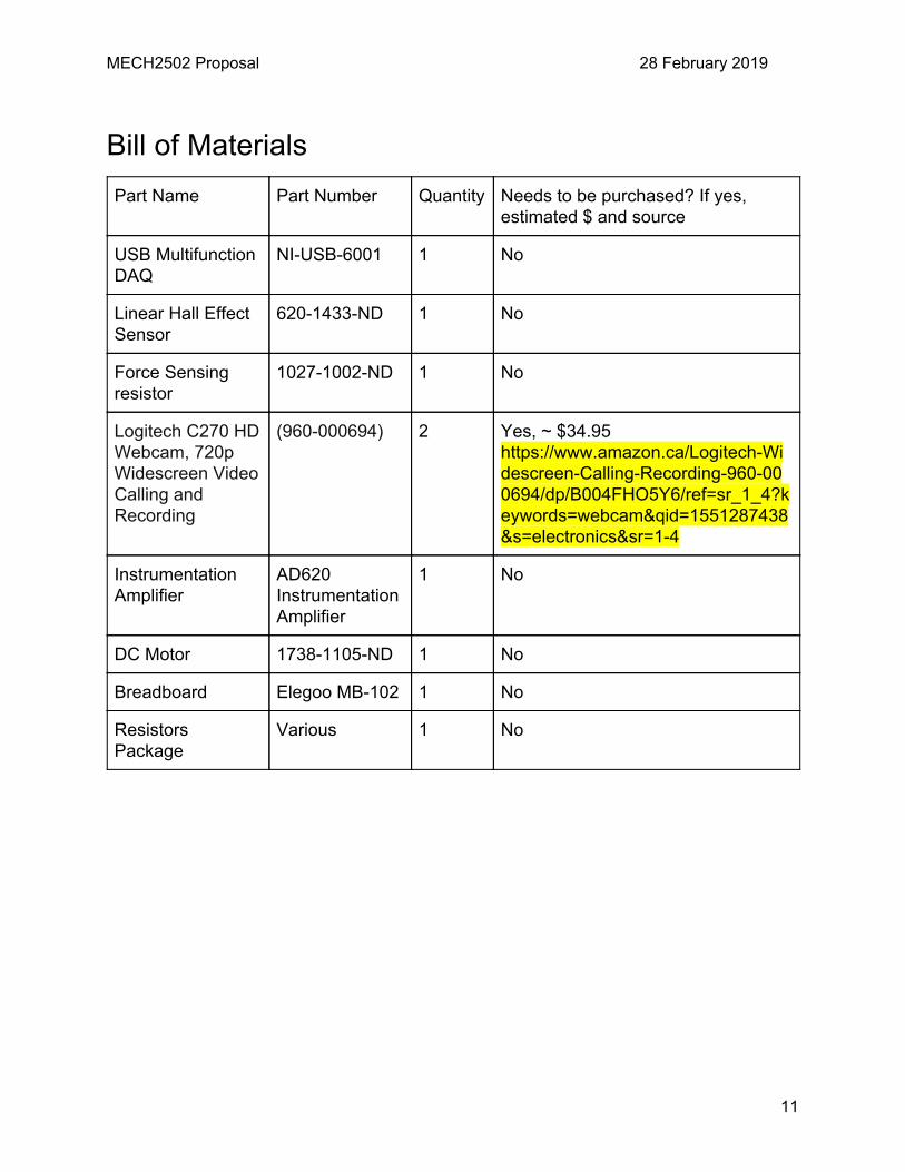
Bill of Materials
Part Name Part Number Quantity Needs to be purchased? If yes, estimated $ and source
USB Multifunction DAQ
NI-USB-6001 1 No
Linear Hall Effect Sensor
620-1433-ND 1 No
Force Sensing resistor
1027-1002-ND 1 No
Logitech C270 HD Webcam, 720p Widescreen Video Calling and Recording
(960-000694)
2 Yes, ~ $34.95 https://www.amazon.ca/Logitech-Widescreen-Calling-Recording-960-000694/dp/B004FHO5Y6/ref=sr_1_4?keywords=webcam&qid=1551287438&s=electronics&sr=1-4
Instrumentation Amplifier
AD620 Instrumentation Amplifier
1 No
DC Motor 1738-1105-ND 1 No
Breadboard Elegoo MB-102 1 No
Resistors Package
Various 1 No
11

MECH2502 Proposal 28 February 2019
Project Planning and Management
Task Name Start Date End Date Assigned To Duration
Idea Generation 11/02/19 22/02/19 12d
In-lecture workshop session 11/02/19 11/02/19 All Members 1d
Offline Idea Development 11/02/19 18/02/19 All Members 8d
Video Pitch 18/02/19 20/02/19 All Members 3d
Review of other groups videos and finalizing project idea
20/02/19 22/02/19 All Members 3d
System Design 22/02/19 08/03/19 15d
Conceptual Design 22/02/19 24/02/19 All Members 3d
Detailed design of sensor/transducer stage
24/02/19 27/02/19 4d
Detailed design of signal conditioning stage
24/02/19 27/02/19 4d
Detailed design of readout/DAQ stage
24/02/19 27/02/19 4d
Proposal write up and submission
27/02/19 28/02/19 All Members 2d
In-lecture feedback session on proposal
04/03/19 04/03/19 All Members 1d
Improving and finalizing the design based on feedback
04/03/19 08/03/19 All Members 5d
System Development 08/03/19 01/04/19 25d
Development of hall-effect sensor and conveyer sub-system
08/03/19 18/03/19 All Members 11d
Development of Webcam and Force resisting sensor sub-system
08/03/19 18/03/19 All Members 11d
12

MECH2502 Proposal 28 February 2019
Development of wheatstone bridge and amplification circuits
08/03/19 18/03/19 All Members 11d
System assembly and calibration
18/03/19 01/04/19 All Members 14d
System Presentation 04/04/19 05/04/19 2d
Presentation of the system in a conference/fair style to a judge panel
04/04/19 05/04/19 All Members 2d
Prepare and submit final group report through Moodle
05/04/19 05/04/19 All Members 1d
Submit peer evaluation of group members performance
05/04/19 05/04/19 All Members 1d
Gantt Chart
13

MECH2502 Proposal 28 February 2019
Appendix (Specifications for needed parts) https://www.digikey.ca/product-detail/en/allegro-microsystems-llc/A1326LUA-T/620-1433-ND/2728148 Linear Hall Effect Sensor: https://www.digikey.ca/en/datasheets/allegromicrosystemsllc/allegro-microsystems-llca132456datasheetashx Force Sensing Resistor: https://cdn2.hubspot.net/hubfs/3899023/Interlinkelectronics%20November2017/Docs/Datasheet_FSR.pdf DC Motor: https://datasheets.globalspec.com/ds/2353/DigiKey/3285C1D2-B3B3-47BC-B8E2-A6A9665B1744 Instrumentation Amplifier: https://www.analog.com/media/en/technical-documentation/data-sheets/AD620.pdf NI USB-6001: http://www.ni.com/pdf/manuals/374369a.pdf Breadboard: https://www.elegoo.com/product/elegoo-3pcs-mb-102-breadboard-830-point-solderless-prototype-pcb-board-kit/
14

MECH2502 Proposal 28 February 2019
Logitech C270 HD Webcam Specifications [3]
Max Resolution 720p/30fps
Focus type Fixed focus
Lens technology standard
Built-in mic mono
FoV 60 degrees
Cable length 1.5 m
15

MECH2502 Proposal 28 February 2019
References [1] MECH2502 Final Project Guidelines [2] https://www.elprocus.com/force-sensing-resistor-technology/ [3] https://www.logitech.com/en-ca/product/hd-webcam-c270#specification-tabular
16