mechanical reverse engineering - philadelphia university€¦ · · 2013-11-06mechanical reverse...
TRANSCRIPT
Dr.-Ing. Mohammed Bani Younis
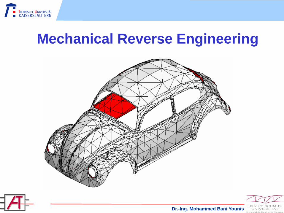
Mechanical Reverse Engineering
Dr.-Ing. Mohammed Bani Younis2
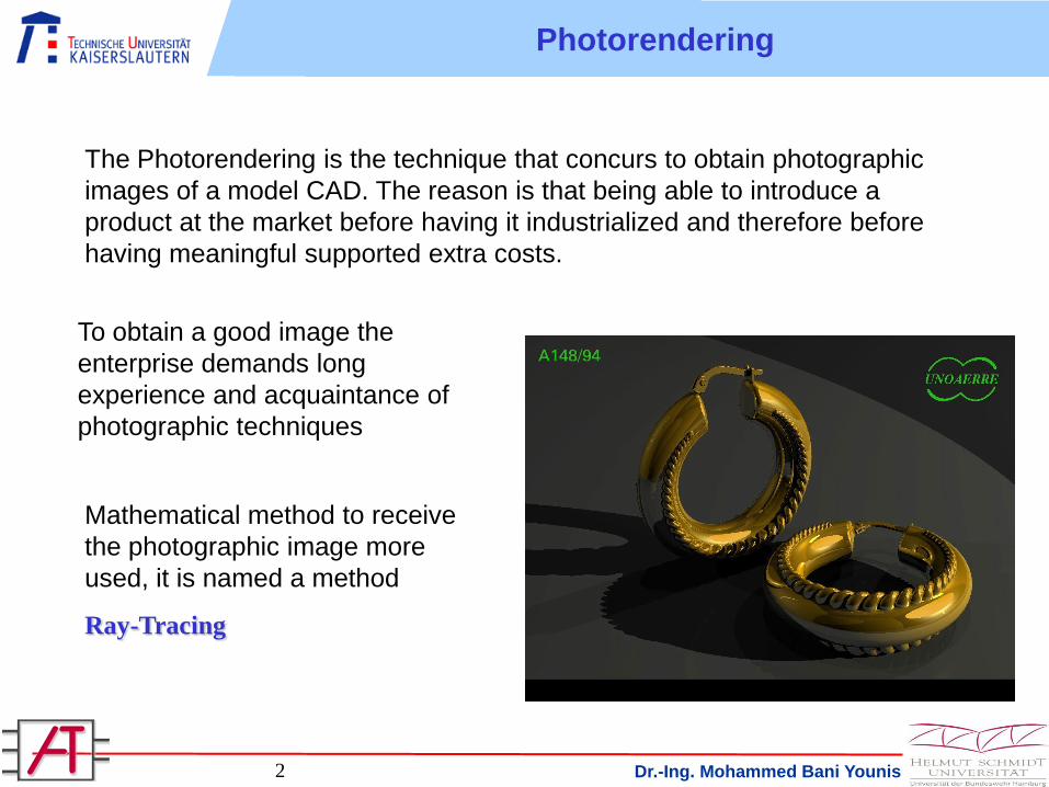
The Photorendering is the technique that concurs to obtain photographic
images of a model CAD. The reason is that being able to introduce a
product at the market before having it industrialized and therefore before
having meaningful supported extra costs.
To obtain a good image the
enterprise demands long
experience and acquaintance of
photographic techniques
Mathematical method to receive
the photographic image more
used, it is named a method
Ray-Tracing
Photorendering
Dr.-Ing. Mohammed Bani Younis3
Every algorithm of photorendering has the need of some information for
being able to calculate a photographic image:
1) Characteristics of the material of the object in terms of:
- Color
- Diffusivity of a particular color
- Superficial finish
- Reflection
- Refraction
- Transparency
- Eventual pattern of covering of the object
Photorendering
Dr.-Ing. Mohammed Bani Younis4
2) Characteristics of the atmosphere in which the object is dipped in
terms of:
- Surrounding objects each one with characteristic detailed lists in
terms of already seen object to be photographed
- Lights that illuminate the atmosphere in diffused way, concentrated,
spot, defined in terms of geometry than of intensity and color
3) Characteristic position of the camera and of the objective
4) Activation of eventual filters actions to improve the image
5) Definition of the “depth of the reflections”
Photorendering
Dr.-Ing. Mohammed Bani Younis6
Rapid Prototyping
Analysis und
DefinitionCreating
prototypes
Design
Implementation
Integration,
test and
acceptance
Application and
maintenance
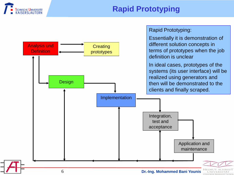
Rapid Prototyping:
Essentially it is demonstration of
different solution concepts in
terms of prototypes when the job
definition is unclear
In ideal cases, prototypes of the
systems (its user interface) will be
realized using generators and
then will be demonstrated to the
clients and finally scraped.
Dr.-Ing. Mohammed Bani Younis7
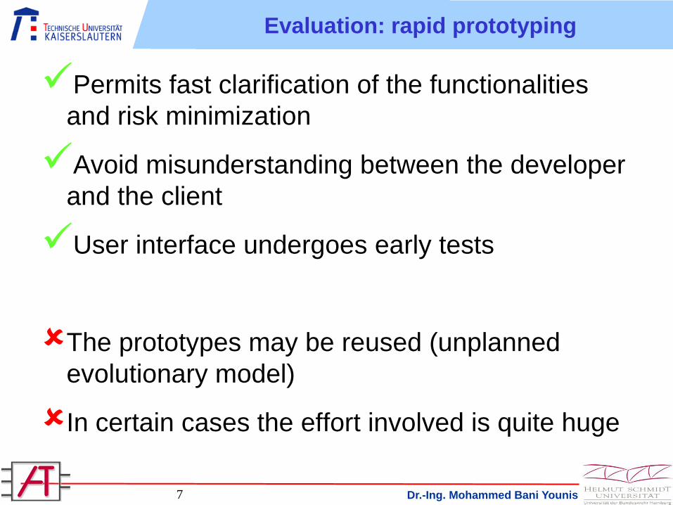
Evaluation: rapid prototyping
Permits fast clarification of the functionalities
and risk minimization
Avoid misunderstanding between the developer
and the client
User interface undergoes early tests
The prototypes may be reused (unplanned
evolutionary model)
In certain cases the effort involved is quite huge
Dr.-Ing. Mohammed Bani Younis8
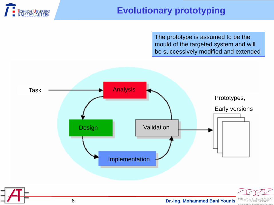
Evolutionary prototyping
The prototype is assumed to be the
mould of the targeted system and will
be successively modified and extended
Task
Prototypes,
Early versions
Analysis
Design
Implementation
Validation
Dr.-Ing. Mohammed Bani Younis9
Evaluation: evolutionary prototyping
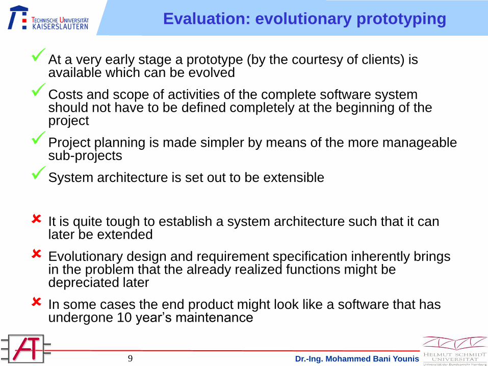
At a very early stage a prototype (by the courtesy of clients) is available which can be evolved
Costs and scope of activities of the complete software system should not have to be defined completely at the beginning of the project
Project planning is made simpler by means of the more manageable sub-projects
System architecture is set out to be extensible
It is quite tough to establish a system architecture such that it can later be extended
Evolutionary design and requirement specification inherently brings in the problem that the already realized functions might be depreciated later
In some cases the end product might look like a software that has undergone 10 year’s maintenance
Dr.-Ing. Mohammed Bani Younis10
Not always it is possible to take decisions on the base of a photographic
image, often it is indispensable to have a model in scale, more or less, of
the object even if a various material from the definitive one.
These cases the Photorendering yields the step to
RAPID PROTOTYPING
With the technique of RAPID PROTOTYPING physical copies can be
obtained of the virtual model in a few hours and with an almost
completely automatic progress.
Many techniques of Rapid Prototyping exist, but all are based on the
SLICING concept:
1) The model is "sliced" by parallel plans and the external outline of
each section is noticed
2) The physical model is built through solidifying a liquid or sintering a
powder section for section
Rapid Prototyping

Dr.-Ing. Mohammed Bani Younis11
RAPID PROTOTYPING
1) Model to be realized
2) Model “Sliced”
3) Construction of the first layer
4) Construction of the successive layers
Rapid Prototyping
Dr.-Ing. Mohammed Bani Younis12
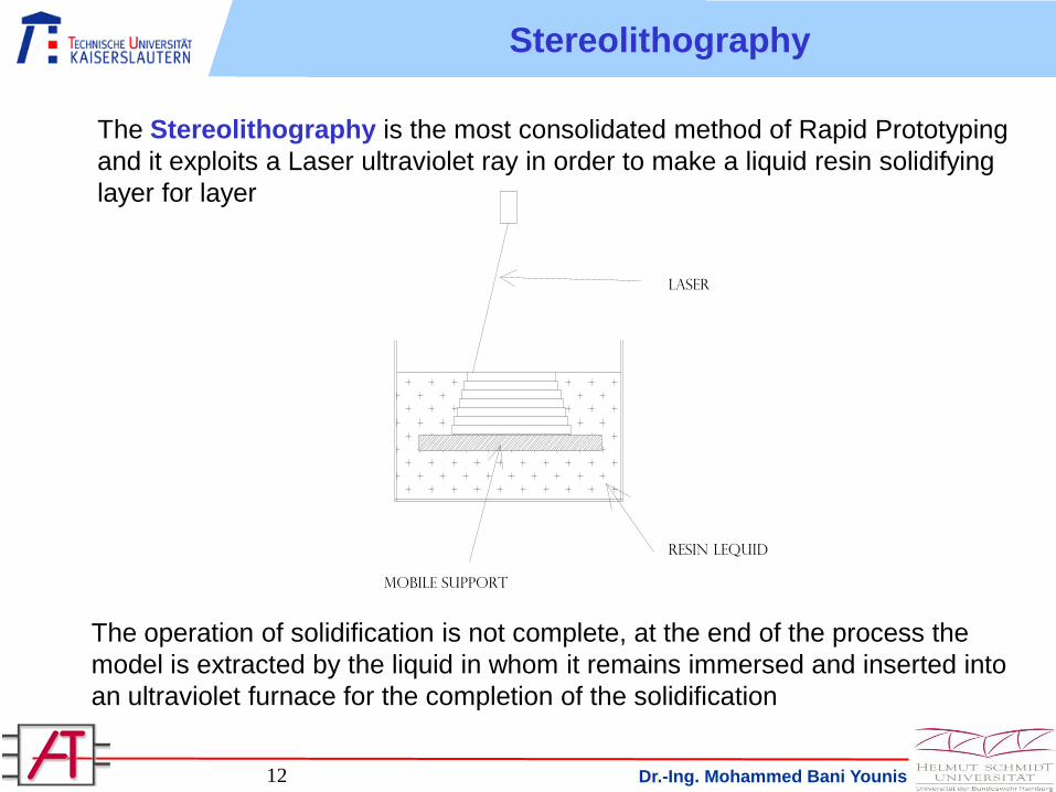
The Stereolithography is the most consolidated method of Rapid Prototyping
and it exploits a Laser ultraviolet ray in order to make a liquid resin solidifying
layer for layer
The operation of solidification is not complete, at the end of the process the
model is extracted by the liquid in whom it remains immersed and inserted into
an ultraviolet furnace for the completion of the solidification
Stereolithography
Resin Lequid
Mobile support
Laser
Dr.-Ing. Mohammed Bani Younis14
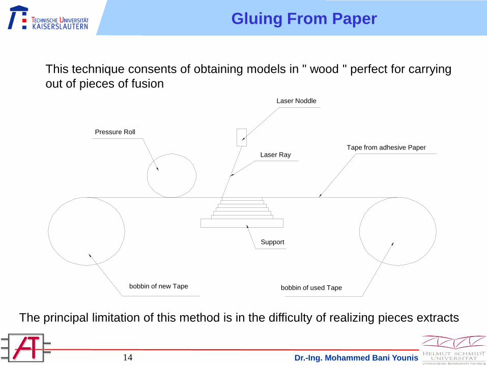
This technique consents of obtaining models in " wood " perfect for carrying
out of pieces of fusion
The principal limitation of this method is in the difficulty of realizing pieces extracts
Gluing From Paper
Pressure Roll
Laser Ray
Laser Noddle
Support
Tape from adhesive Paper
bobbin of used Tapebobbin of new Tape
Dr.-Ing. Mohammed Bani Younis15
The method of selective synthesizing which is now very promising and it is
based on analogous concept of the Stereolithography but are used for liquid
resin of metal powders .
Thanks to the laser the powders are made to fuse and to tie with the below
layer in localized way (selective). In this way prototypes in metal can be
obtained directly. This issue is currently in course of continuous search on the
usable types of metal with the objective to reliably utilization of powders from
ferrous materials.
The great advantage of this method is to be able to obtain the metallic mould
directly rather than a model in resin, mould that can rather be used for the
production of pre series consisting in the event of the molding of metals and
complete series in the event of plastic arts.
Selective synthesizing
Dr.-Ing. Mohammed Bani Younis16
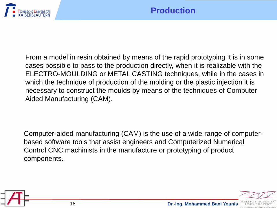
From a model in resin obtained by means of the rapid prototyping it is in some
cases possible to pass to the production directly, when it is realizable with the
ELECTRO-MOULDING or METAL CASTING techniques, while in the cases in
which the technique of production of the molding or the plastic injection it is
necessary to construct the moulds by means of the techniques of Computer
Aided Manufacturing (CAM).
Computer-aided manufacturing (CAM) is the use of a wide range of computer-
based software tools that assist engineers and Computerized Numerical
Control CNC machinists in the manufacture or prototyping of product
components.
Production
Dr.-Ing. Mohammed Bani Younis17
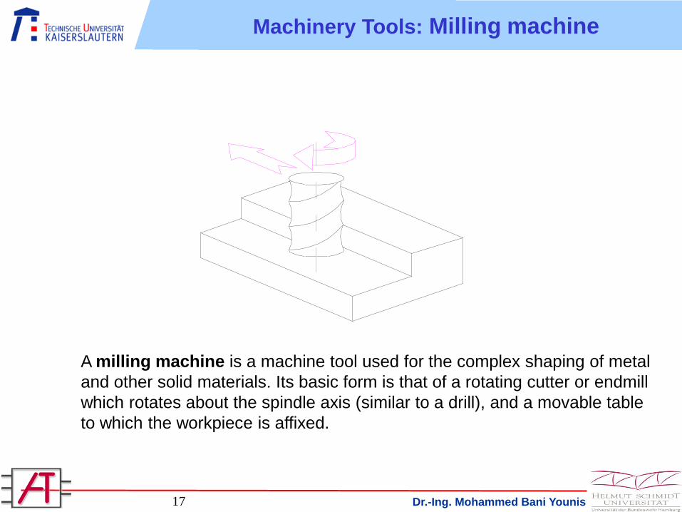
A milling machine is a machine tool used for the complex shaping of metal
and other solid materials. Its basic form is that of a rotating cutter or endmill
which rotates about the spindle axis (similar to a drill), and a movable table
to which the workpiece is affixed.
Machinery Tools: Milling machine
Dr.-Ing. Mohammed Bani Younis18
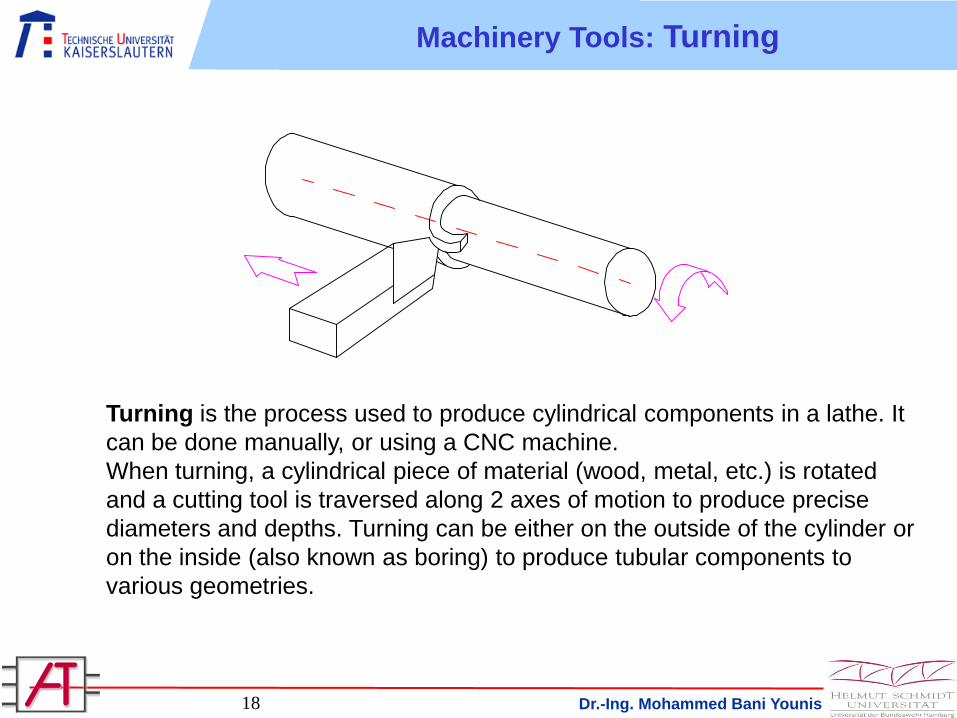
Turning is the process used to produce cylindrical components in a lathe. It
can be done manually, or using a CNC machine.
When turning, a cylindrical piece of material (wood, metal, etc.) is rotated
and a cutting tool is traversed along 2 axes of motion to produce precise
diameters and depths. Turning can be either on the outside of the cylinder or
on the inside (also known as boring) to produce tubular components to
various geometries.
Machinery Tools: Turning
Dr.-Ing. Mohammed Bani Younis19
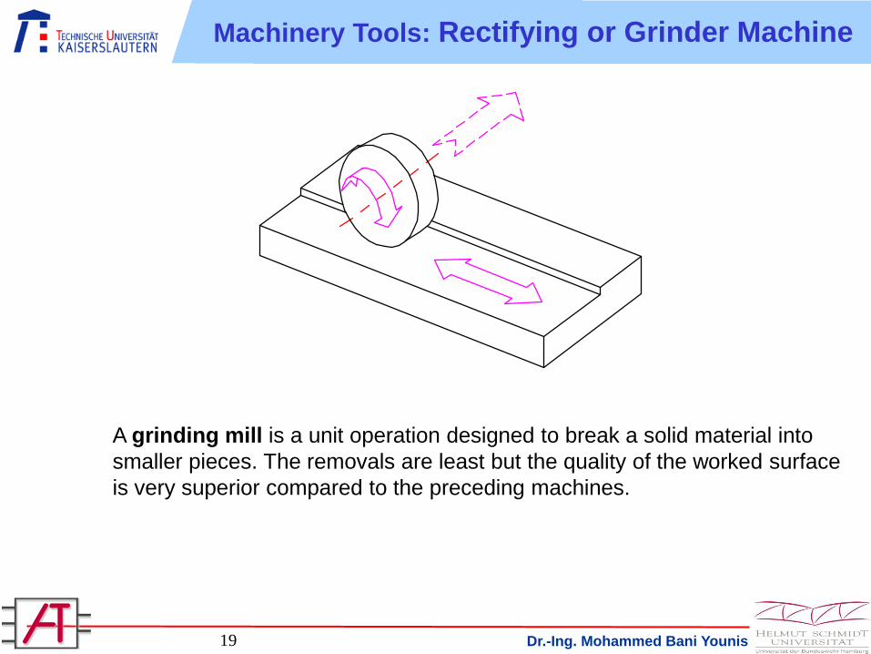
A grinding mill is a unit operation designed to break a solid material into
smaller pieces. The removals are least but the quality of the worked surface
is very superior compared to the preceding machines.
Machinery Tools: Rectifying or Grinder Machine
Dr.-Ing. Mohammed Bani Younis20
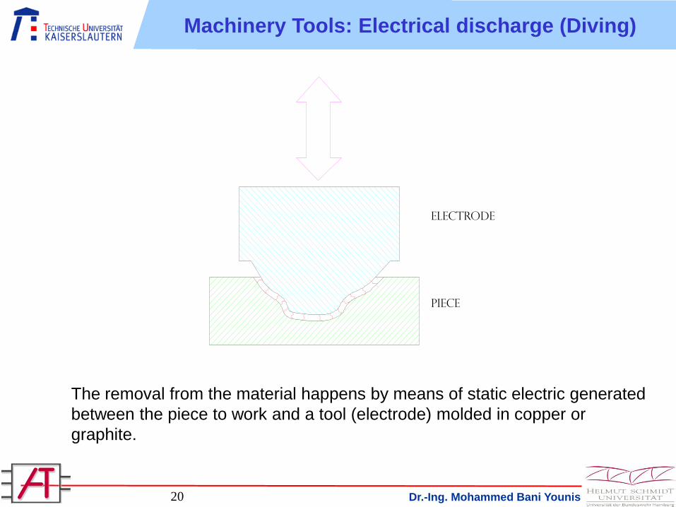
The removal from the material happens by means of static electric generated
between the piece to work and a tool (electrode) molded in copper or
graphite.
Machinery Tools: Electrical discharge (Diving)
Piece
electrode
Dr.-Ing. Mohammed Bani Younis21
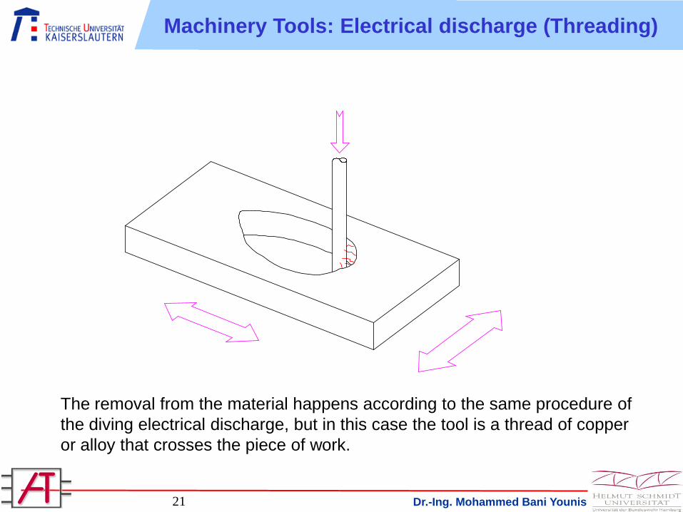
Machinery Tools: Electrical discharge (Threading)
The removal from the material happens according to the same procedure of
the diving electrical discharge, but in this case the tool is a thread of copper
or alloy that crosses the piece of work.
Dr.-Ing. Mohammed Bani Younis22
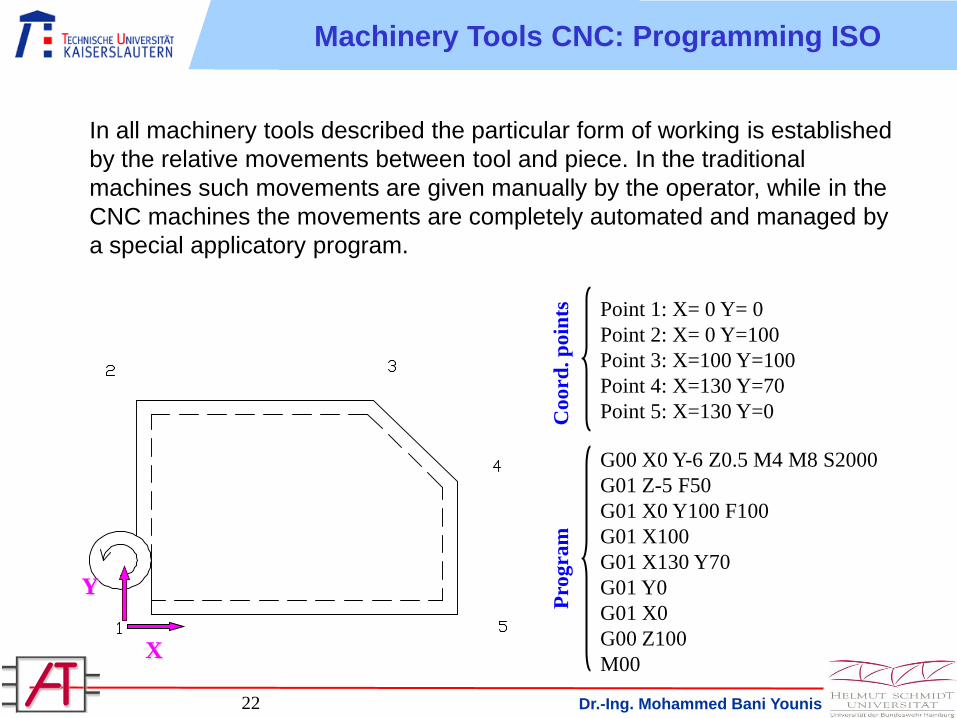
In all machinery tools described the particular form of working is established
by the relative movements between tool and piece. In the traditional
machines such movements are given manually by the operator, while in the
CNC machines the movements are completely automated and managed by
a special applicatory program.
Point 1: X= 0 Y= 0
Point 2: X= 0 Y=100
Point 3: X=100 Y=100
Point 4: X=130 Y=70
Point 5: X=130 Y=0
G00 X0 Y-6 Z0.5 M4 M8 S2000
G01 Z-5 F50
G01 X0 Y100 F100
G01 X100
G01 X130 Y70
G01 Y0
G01 X0
G00 Z100
M00
Co
ord
. p
oin
ts
Pro
gra
m
X
Y
Machinery Tools CNC: Programming ISO
Dr.-Ing. Mohammed Bani Younis23
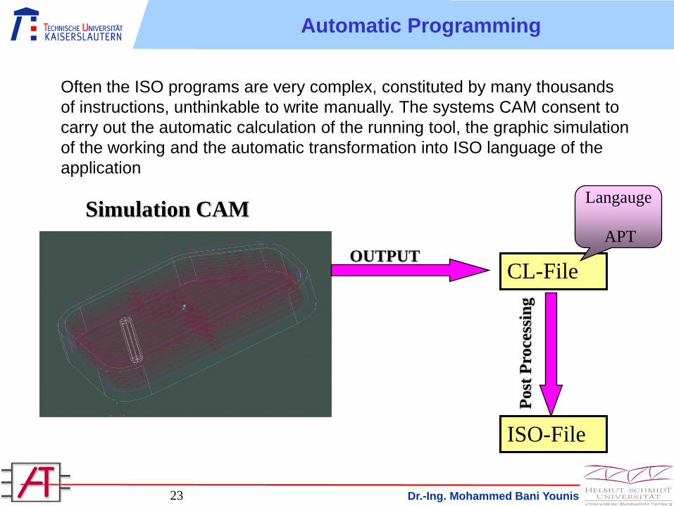
Often the ISO programs are very complex, constituted by many thousands
of instructions, unthinkable to write manually. The systems CAM consent to
carry out the automatic calculation of the running tool, the graphic simulation
of the working and the automatic transformation into ISO language of the
application
Simulation CAM
CL-File
ISO-File
OUTPUT
Post
Pro
cess
ing
Langauge
APT
Automatic Programming
Dr.-Ing. Mohammed Bani Younis24
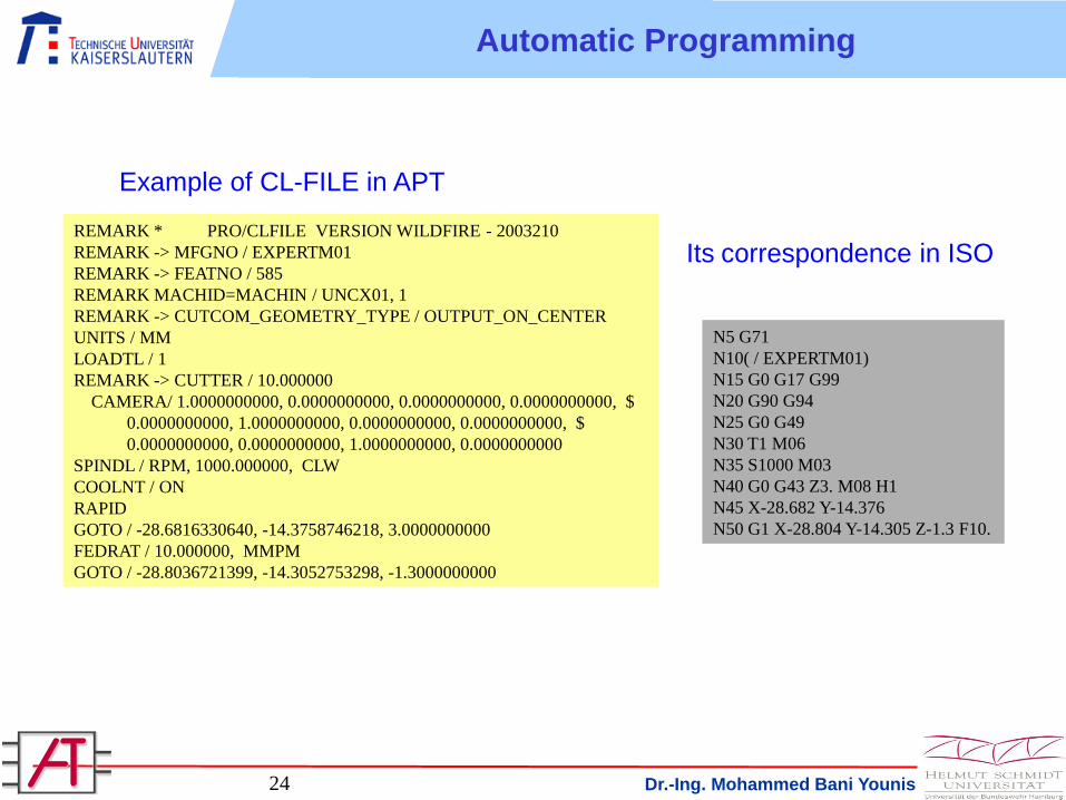
REMARK * PRO/CLFILE VERSION WILDFIRE - 2003210
REMARK -> MFGNO / EXPERTM01
REMARK -> FEATNO / 585
REMARK MACHID=MACHIN / UNCX01, 1
REMARK -> CUTCOM_GEOMETRY_TYPE / OUTPUT_ON_CENTER
UNITS / MM
LOADTL / 1
REMARK -> CUTTER / 10.000000
CAMERA/ 1.0000000000, 0.0000000000, 0.0000000000, 0.0000000000, $
0.0000000000, 1.0000000000, 0.0000000000, 0.0000000000, $
0.0000000000, 0.0000000000, 1.0000000000, 0.0000000000
SPINDL / RPM, 1000.000000, CLW
COOLNT / ON
RAPID
GOTO / -28.6816330640, -14.3758746218, 3.0000000000
FEDRAT / 10.000000, MMPM
GOTO / -28.8036721399, -14.3052753298, -1.3000000000
N5 G71
N10( / EXPERTM01)
N15 G0 G17 G99
N20 G90 G94
N25 G0 G49
N30 T1 M06
N35 S1000 M03
N40 G0 G43 Z3. M08 H1
N45 X-28.682 Y-14.376
N50 G1 X-28.804 Y-14.305 Z-1.3 F10.
Example of CL-FILE in APT
Its correspondence in ISO
Automatic Programming

Dr.-Ing. Mohammed Bani Younis25
The need for spare parts is increasing as technology continues to evolve.
Companies that manufacture or produce constantly changing parts use reverse
engineering as a primary inspection tool for recreation of spare parts. Reverse
engineering refers to the process of obtaining a CAD model from an existing
physical part.
Advances in laser scanning technologies have facilitated this process by sampling
part surface data with speed and accuracy. With the help of this technology, it is
possible to acquire the geometry of a part having complex and freeform surfaces.
Laser scanning presents options, the previously used methods do not allow.
Damaging parts surfaces due to contact is not a problem with laser scanning.
Model
CAD
Phsical
Model
Trasformation
Of Physical Model
Updating
Model
CAD
Reverse Engineering
Digitalization
of Physical Model
Dr.-Ing. Mohammed Bani Younis26
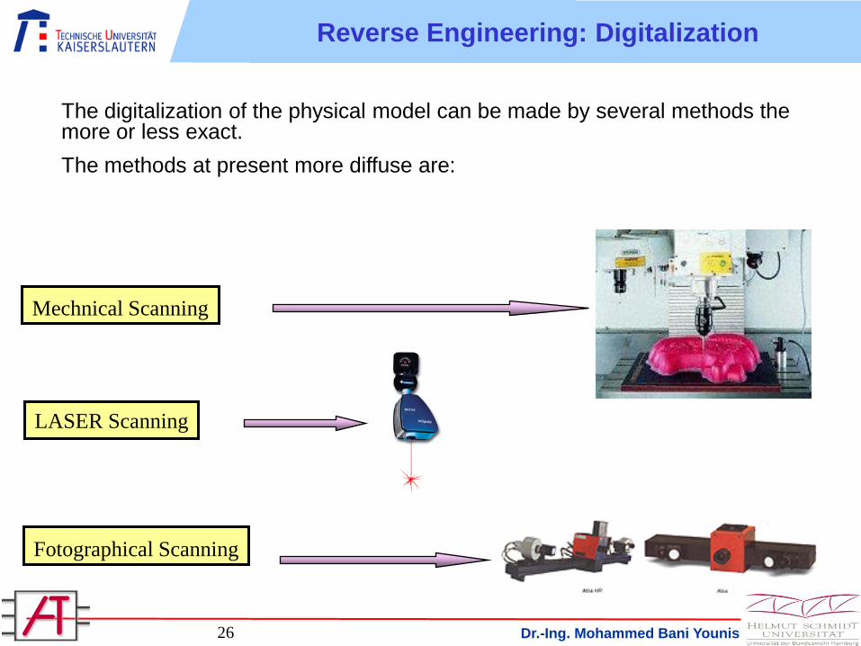
The digitalization of the physical model can be made by several methods the more or less exact.
The methods at present more diffuse are:
Mechnical Scanning
LASER Scanning
Fotographical Scanning
Reverse Engineering: Digitalization