mechanics of plates - arxiv · throughout the work, the theory of elastic plates is used as a...
TRANSCRIPT

arX
iv:1
110.
2050
v4 [
phys
ics.
clas
s-ph
] 5
Jan
201
2
Mechanics of plates
Vladimír Balek1
Department of Theoretical Physics, Comenius University, Bratislava, Slovakia
The theory of deformed plates in mechanical equilibrium is formulated and properties of circular plates
lifted at the center are discussed.
I. Introduction
The interest in the mechanics of plates dates back to 1809 when the French Academy of Sciences
donated an award for the best work on oscillating plates (Timoshenko 1952). The donation was
iniciated by Napoleon Bonaparte who was impressed by the demonstration of Chladni patterns at one
of the Academy meetings. Three years later the only contestant, Sophie Germain, submitted a treatise
where she proposed a variation principle corresponding to a distinctly nonphysical value of Poisson’s
ratio ν = 1. The resulting differential equation, when rederived by Lagrange, was correct, since the
correct equation does not contain Poisson’s ratio. Nevertheless the physical basis of the underlying
variation principle remained unclear, which was hardly surprising since the theory of elasticity did not
exist yet. First step towards its formulation was Poisson’s memoir on the theory of plates published
in 1814, shortly after the second, revised version of Germain’s work appeared. Although two years
later Sophie Germain was finally, at third attempt, given the award, the theory of elastic plates in its
present form was formulated by Kirchhoff not earlier than in 1850. The extension to plastic plates
appeared still later, after the concept of plasticity emerged in the experiments by Tresca.
The theory of elastic plates is nowadays a standard part of textbooks on the mechanics of de-
formable bodies; see, for example, Landau and Lifshitz (1965). The theory of plasticity is explained
in classical books by Hill (1950) and Kachanov (1956), and mathematics of the deformation theory of
plasticity is described in detail in the monograph by Temam (1983). Properties of plastic plates are
discussed in Kachanov’s book in the chapter entitled Plane Stress. Plates are considered in the frame-
work of the theory of plastic flow, but most results can be carried over into the deformation theory
simply by replacing velocities by deflections. Other results on plastic plates can be found in papers
1e-mail address: [email protected]
1

published in engineering journals, and still other results can be obtained by applying dimensional
reduction to what is known from the theory of extended plastic bodies.
In this work all pieces are put together and a concise and self-contained deformation theory of
plastic plates is developed. Throughout the work, the theory of elastic plates is used as a model. In
section II the concepts of elasticity and plasticity are introduced, in section III constitutive equations
are constructed, in section IV differential equations for plates in mechanical equilibrium are formulated
and boundary conditions for them are discussed, in section V deformation energy is computed, in
section VI variational principle for deformed plates is investigated, in section VII two mixed kind of
deformations are discussed and in section VIII some simple examples are presented.
II. Elasticity and plasticity
Elastic deformation is a reversible process: the body returns to its initial state after the deforming
forces have been lifted. Moreover, the deformation is proportional to the applied load. This is just
a demonstration of the general law stating that the response is linear in its cause in case the cause
is small. Linear relation between the stress inside the body to which an external load is applied and
the resulting deformation of the body is called generalized Hooke’s law. Elastic properties of isotropic
materials are characterized by two parameters only, Young’s modulus of elasticity E (with the physical
dimension of pressure) and Poisson’s ratio ν (dimensionless). Consider an homogenous and isotropic
beam fastened at one end and subject to the action of an aligned load at the other end, and denote
relative dilation of the beam in the direction of its axis by ǫ, relative dilation of the beam in the lateral
direction by ǫ′, and pressure load (force per unit area) by τ . In the elastic regime it holds
ǫ =1
Eτ, (1)
and
ǫ′ = − ν
Eτ. (2)
The first equation is the original Hooke’s law, the famous ut tensio, sic vis (as the extension, so the
force) stated by Robert Hooke in 1660. The generalized Hooke’s law follows from equations (1) and
(2), if one applies them to an infinitesimal volume of the body.
The values of Poisson’s ratio are restricted by the requirement that the deformation energy per
unit volume is positively definite. This requirement implies that Poisson’s ratio must be from the
interval 〈−1, 1/2〉. If it is 0, the lateral section of the beam does not change when the beam is
2

stretched; if it is 1/2, the volume of the beam remains constant; and if it is from the interval (0, 1/2),
the beam contracts in the lateral direction and its volume increases. For known materials, Poisson’s
ratio assumes values typically from 0.3 to 0.4. It equals, for instance, 0.30 for steel, 0.34 for copper
and 0.42 for gold.
After the pressure load applied to the beam reaches a certain critical value, called yield limit,
the beam becomes plastic. In this regime, the deformation is irreversible; after the external force is
removed, some residual dilation of the beam remains. The linear character of the deformation is lost,
too. For a large class of materials, stretching of the beam proceeds in two clearly distinguished stages.
First the beam dilates while the force remains more or less unchanged; then the beam continues to
dilate only if the force starts to grow again. This two stages are called yielding and hardening. (The
latter term refers to the fact that if we lift the force and then apply it again, plasticity takes over only
after the force reaches the value from which it previously jumped to zero. Consequently, a larger force
is needed to start the plastic deformation than for the first time.) In the course of yielding, Hooke’s
law in the form (1) is replaced by an even simpler law
τ = E , (3)
where E is the yield limit. The law is true for ǫ1 < ǫ < ǫ2, where ǫ1 and ǫ2 are the relative dilations at
which yielding and hardening take over respectively; particularly, ǫ1 = E/E. One introduces two limit
kinds of plasticity: rigid plasticity, in which the beam does not deform at all until the stress reaches
the yield limit, and perfect plasticity, in which no hardening takes place so that the beam stretches
to infinity at the yield limit. Rigid plasticity means E = ∞, ǫ1 = 0, while perfect plasticity means
ǫ2 = ∞. In fig. 1, the behavior of a deformable beam is represented schematically by the solid line,
with ’E’ standing for elastic deformation, ’Y’ standing for yielding, and ’H’ standing for hardening.
The rigid-plastic and perfect plastic limits are depicted by the dotted-line segments denoted ’RP’ and
’PP’ respectively.
A realistic description of plasticity is provided by the incremental theory, or the theory of plastic
flow, in which the stress inside the body is related to the increment of the plastic deformation rather
that to the plastic deformation itself. However, if we are interested in the initial stage of plastic
deformation only, we can obtain satisfactory results also from the deformation theory in which the
stress is related to the plastic part of the deformation in a similar way as to the elastic part. In other
words, plasticity is regarded as a kind of a nonlinear elasticity. Particularly, one assigns a deformation
3

H
PPYRP
E
τ
ε
Fig. 1: Extension of a beam
energy to a body, which means that one resigns on the description of the relaxation of the body to
the new equilibrium state after the load has been lifted. The incremental and the deformation theory
coincide if the body is simply loaded, which means if it undergoes, for instance, a dilation or a shear,
but not a dilation followed by a shear. A close connection between the two theories exists even if the
body is arbitrarily loaded, provided it is rigid-plastic. The deformation in the former theory is then
obtained by integrating the deformation in the latter theory over time.
The simplest theory of plasticity is the deformation theory of perfectly plastic rigid-plastic bodies.
The theory can be viewed as the rigid limit of the Hencky theory (the deformation theory of perfect
elastic plasticity), or as the deformation variant of the Sain-Venant–Levi–von Mises theory (the incre-
mental theory of perfect rigid plasticity). Both theories are discussed in detail in Kachanov (1956).
The deformation theory of perfect rigid plasticity is, despite all its simplifications, extensively used
in engineering. It is the basis of limit analysis, evaluation of the loads at which the plasticity takes
over and the corresponding deformations of the body. In the limit analysis, the assumptions about
perfect plasticity and validity of the deformation theory do not play any role, and the only remaining
simplification, the assumption about rigid plasticity, provides us with results that can be interpreted
as limit results for real bodies.
III. Constitutive equation
The full system of equations determining the form of a deformable body in equilibrium consists of
constitutive equation, equation of balance of forces, and boundary conditions for the latter equation.
If the body is perfectly plastic, constitutive equation must be supplemented by constitutive inequality.
4

Neither constitutive equation nor equation of balance of forces are formulated for the plate directly.
One postulates them for the extended body and then rewrites them into the form valid for the plate.
This procedure can be called dimensional reduction since one effectively passes from three to two
dimensions. When doing so one assumes that the plate is thin (its thickness is much smaller than
the characteristic scale of deformation), and that the bending of the plate is small (the deflection
is much smaller than the thickness of the plate; see Landau and Lifshitz 1965). In the literature
sometimes a different approach is used, based on the original work by Kirchhoff (see Timoshenko
and Woinowsky-Krieger 1959). One starts from Kirchhoff hypotheses stating, first, that the sections
that were orthogonal to the mid-plane of the plate at the beginning remain orthogonal to it after the
deforming forces have been applied, and second, that the mid-plane is neutral, that means it is bent
but neither stretched nor compressed. Both hypotheses are, however, immediate consequences of the
assumptions cited above.
Consider a plate with a constant thickness h whose mid-plane is placed in the plane (x, y) before
the deformation, and denote the deflection of the mid-plane of the deformed plate from the plane
(x, y) by w. The stress inside the plate and the resulting deformation are described by two symmetric
2× 2 matrices, tensor of moments M and Hessian matrix W ,
M =
Mxx Mxy
Myx Myy
. W =
Wxx Wxy
Wyx Wyy
, (1)
The components of the Hessian matrix are the second partial derivatives of the function w(x, y),
W =
∂2w
∂x2∂2w
∂x∂y∂2w
∂x∂y
∂2w
∂y2
.
The matrix is symmetric and its trace equals Laplacian acting on w,
trW = ∆w. (2)
The components of the tensor of moments are moments per unit width induced by the stresses acting
parallel to the plate. The moments Mxx and Myy bend the plate in the direction of the axes x and y
respectively, and the moments Mxy and Myx twist the plate in the planes (x, z) and (y, z) respectively.
The twisting moments are identical, so that the tensor of moments is symmetric just like the Hessian
matrix.
5

Constitutive equation determines the stress arising inside the body in terms of deformation. For
an elastic body, the equation reduces to the generalized Hooke’s law. Constitutive equation of a plate
is a matrix equation relating the tensor of moments to the Hessian matrix. It is obtained from the
constitutive equation of an extended body via dimensional reduction, by which 3 × 3 matrices are
replaced by 2 × 2 ones. If the deformation is elastic and the material of the plate is isotropic, the
constitutive equation reads
M = −D[(1− ν)W + ν trWI], (3)
where D = Eh3/[12(1 − ν2)]. The constant D is called flexural rigidity. We can see that the
constitutive equation of the elastic isotropic plate is the most general relation between two symmetric
matrices that is both linear and isotropic. Since it is obtained by dimensional reduction of the
generalized Hooke’s law, it can be called two-dimensional Hooke’s law.
The starting point for the formulation of the constitutive equation of the plastic body is the yield
criterion. It is a constraint on the stress inside the body defining the state of yielding or, if the body
is perfectly plastic, the plastic state itself. The first yield criterion was proposed in 1868 by Tresca,
a French engineer who pioneered the research of plasticity. Tresca’s criterion was later modified by
von Mises. The purpose was to simplify the analysis; however, the new criterion happened to do
even better than the original one when confronted with experimental data. The yield criterion can be
represented by a surface in the space of main stresses called yield diagram. For von Mises’ criterion,
the yield diagram is an infinite cylinder with the radius of the base√
2/3E , whose axis passes through
the origin and is deflected from all three coordinate axes by the angle π/4. Von Mises’ criterion can
be slightly generalized so that an improved description of some materials, as marble and sandstone,
is achieved. The generalization was proposed in Yang (1980a); more specifically, it was the first of
the two generalizations proposed there, describing the effect of hydrostatic stress on yielding. In
the generalized von Mises’ criterion materials are characterized, in addition to the yield limit E , by
the dimensionless parameter κ assuming values from the interval 〈0, 1/2〉. (In the notation of Yang,
κ = α(2 − α)/(1 − α)2.) For κ = 0 the yield diagram is sphere, for κ increasing from 0 to 1/2 it is a
gradually stretching rotational ellipsoid whose axis is deflected by the angle π/4 from all coordinate
axes, and for κ = 1/2 it is von Mises’ cylinder. Referring to these shapes we can call the generalized
von Mises’ criterion with an arbitrary value of κ ellipsoid criterion, and the criteria with κ = 0 and
κ = 1/2 spherical criterion and cylindric criterion respectively.
If we pass from an extended body to a plate, the yield criterion undergoes dimensional reduction
6

just like Hooke’s law. As a result, a constraint on the tensor of moments arises. Particularly, the
generalized von Mises’ criterion reduces to
(1 + κ)trM2 − κ(trM)2 = M2
0 . (4)
where M0 = Eh2/4. Expressed in terms of main moments (eigenvalues of the matrix M), this equation
reads
M2
1 +M2
2 − 2κM1M2 = M2
0 . (5)
The yield diagram is now a planar curve that can be obtained as an intersection of the three-
dimensional yield diagram with the horizontal plane. For κ = 0 the yield diagram is circle, while
for κ increasing from 0 to 1/2 inclusive it is a gradually stretching ellipse. In fig. 2, three diagrams
of this class are shown, drawn by the solid line. The form of the diagrams suggests that we call the
-M0
M0
0
-M0 M00
M2
M1
Fig. 2: Yield diagrams
yield criterion in question elliptical criterion; or, if κ = 0, circular criterion. One can formulate other
theories of plasticity starting from other yield criteria. By doing so one does not need to care about
the three-dimensional theory; instead, one can postulate yield criteria that are two-dimensional from
the beginning. Let us mention an alternative to the elliptical criterion obtained in this way, considered
appropriate for concrete plates. It is the square criterion proposed by Johanson (see Mansfield 1957),
max (|M1|, |M2|) = M0. (6)
In fig. 2, this criterion is depicted by the dotted line.
7

If one inserts stresses at the given point of the body into the yield criterion, one can decide what
kind of deformation occurs there. For a perfectly plastic body in equilibrium, only two regimes of
deformation are possible. If the stresses fit inside the yield diagram, the deformation is either elastic
or there is no deformation at all depending on whether the body is elastoplastic or rigid-plastic; if,
however, the stresses are placed on the surface of the yield diagram, the deformation possibly contains
a plastic part. With the stresses outside the yield diagram there exists no equilibrium. We are talking
of an extended body, but all we have said can be applied to a plate, too, if the word ’stresses’ is
replaced by the word ’moments’. Define the norm of the tensor of moments ‖M‖ as the left hand
side of the two-dimensional yield criterion, if written with M0 on the right hand side. Then the
perfectly plastic plate can be in equilibrium only if the tensor of moments satisfies the constraint
called constitutive inequality,
‖M‖ ≤ M0. (7)
The plate is deformed elastically or remains flat if ‖M‖ < M0, and possibly undergoes plastic defor-
mation if ‖M‖ = M0.
Let us proceed to the constitutive equation for the plastic plate. Once again, the equation is
obtained by dimensional reduction. We will restrict ourselves to the perfectly plastic rigid-plastic
plate obeying the deformation theory. For such plate, the Hessian matrix in the regime of plastic
deformation is proportional to minus gradient of the norm ‖M‖,
W = −C∂‖M‖∂M
, C > 0. (8)
In components, the equation reads
Wxx = −C∂‖M‖∂Mxx
, Wxy = −C∂‖M‖∂Mxy
, Wyy = −C∂‖M‖∂Myy
.
For the elliptical criterion we obtain
W = −C1[(1 + κ)M − κtrMI], (9)
where C1 = C/‖M‖ = C/M0. Next we solve for M and fix the constant of proportionality by the
yield criterion. As a result we find
M = −D (1− κ)W + κtrWI√
(1− κ)trW 2 + κ(trW )2, (10)
8

where D = M0/√1− κ2. This is the constitutive equation we have sought. After comparing it with
the two-dimensional Hooke’s law we conclude that D can be regarded as ’plastic flexural rigidity’ and
κ as ’plastic Poisson’s ratio’.
To complete the theory we must specify the behavior of the plate if the stress is not large enough
to produce plastic deformation. A deformed perfectly plastic rigid-plastic plate consists, in general,
of two parts that are to be treated separately: the plastic domain, where W 6= 0 and M is given by
the constitutive equation, which means that ‖M‖ = M0, and the rigid domain, where W = 0 and
‖M‖ ≤ M0. Obviously, in the rigid domain the plate is flat; or at least, as we will see, piecewise flat.
IV. Equation of balance of forces
In equilibrium, the forces acting on a column of matter reaching from one face of the plate to the
other must compensate each other. Obviously, this requirement is the same for elastic and plastic
plates. Suppose the plate is bent by the lateral pressure load q. Equation of balance of forces then
reads
∇∇ ·M = −q, (1)
where the expression on the left hand side is the sum of the second derivatives of M ,
∇∇ ·M =∂2Mxx
∂x2+ 2
∂2Mxy
∂x∂y+
∂2Myy
∂y2.
The double gradient is a symmetric 2 × 2 matrix just like the tensor of moments. In general, we
can define the scalar product of matrices as the trace of their matrix product. Thus, for symmetric
matrices we have
A · B = tr (AB) = AxxBxx + 2AxyBxy +AyyByy,
which immediately yields the expression for ∇∇ ·M above.
By combining the equation of balance of forces with the constitutive equation, we arrive at the
differential equation for deflection only. Consider first an elastic plate. If the material of the plate is
not only isotropic but also homogeneous, D and ν = const, we find
∆trW ≡ ∆∆w =q
D. (2)
In such a way, the deflection of a homogenous and isotropic elastic plate in equilibrium obeys an
inhomogeneous biharmonic equation, called Lagrange equation, with the source proportional to the
9

pressure load. Note that, as mentioned in the introduction, the equation does not contain Poisson’s
ratio.
Since the deformation of the plate is governed by a differential equation of fourth order, we have
to impose two boundary conditions on it. Let us introduce three basic sets of boundary conditions,
corresponding to clamped, simply supported and free plate. Denote the edge of the mid-plane of the
relaxed plate (a closed curve in the (x, y) plane) by C. The clamped plate is fixed steadily at the
edge, hence it satisfies the conditions
w = 0 on C, (3)
and∂w
∂n= 0 on C, (4)
where ∂/∂n is the derivative in the direction normal to the curve. The remaining two sets of boundary
conditions contain also components of the matrices M and W . Denote the unit vectors normal and
tangential to the curve by n and t respectively, and define normal, mixed and tangential components
of a symmetric matrix as Ann = A · nn = Axxn2x + 2Axynxny + Ayyn
2y, Ant = A · nt = Axxnxtx +
Axy(nxty + nytx) + Ayynzty and Att = A · tt = Axxt2x + 2Axytxty + Ayyt
2y. The simply supported
plate is fixed by a bar that allows it to rotate freely, and satisfies the condition (3) together with the
condition
Mnn = 0 on C. (5)
The constraint on the matrix M follows from the very concept of mechanical equilibrium: the moment
of the bar acting on the plate must be zero, otherwise the bar would make the plate rotate around
the groove. Rewritten in terms of the matrix W , the constraint reads
Wnn + νWtt = 0 on C. (6)
The free plate is not fixed at all, so that the bending moment Mnn as well as some effective shearing
force Qn at its edge must be zero. As a result, the free plate shares the condition (5) with the simply
supported plate, and in addition it obeys the condition
Qn ≡ n∇ ·M − ∂Mnt
∂l= 0 on C, (7)
where the first term on the left hand side is the linear combination of the first derivatives of M , with
the coefficients equal to the components of the vector n,
n∇ ·M = nx∂Mxx
∂x+ nx
∂Mxy
∂y+ ny
∂Mxy
∂x+ ny
∂Myy
∂y,
10

and ∂/∂l is the gradient in the direction tangential to the curve C. (The scalar product n∇ ·M is a
sum of four terms instead of three, because the matrix n∇ is not symmetric.) Passing to the Hessian
matrix, we find∂ trW
∂n− (1− ν)
∂Wnt
∂l= 0 on C. (8)
In conditions (6) and (8) Poisson’s ratio, after all, enters the theory.
Let us summarize. An elastic plate in equilibrium satisfies the differential equation (2) and two
boundary conditions: conditions (3) and (4), if it is clamped, conditions (3) and (6), if it is simply
supported, and conditions (6) and (8), if it is free. From the theory of partial differential equations it
follows that the function solving this problem exists and is unique.
Now we wish to formulate conditions of equilibrium of the plastic plate. Consider a perfectly plastic
rigid-plastic plate whose behavior is described by the deformation theory, and suppose it obeys the
elliptical criterion. Suppose furthermore that the part of the plate we are interested in lays in the
plastic domain. By inserting from the constitutive equation into the equation of balance of forces we
obtain
∇∇ ·W =q
D , (9)
where
W =(1− κ)W + κtrWI
√
(1− κ)trW 2 + κ(trW )2. (10)
In such a way, the deflection in the plastic domain is given by an equation of fourth order again, but
unlike in the elastic case this equation is nonlinear. Boundary conditions remain the same as in the
elastic case, provided we express the ’moment’ and the ’force’ conditions in terms of the tensor of
moments. After we pass from the tensor of moments to the Hessian matrix, the ’moment’ condition
reduces to (6) with ν replaced by κ, but the ’force’ condition is more complicated than (8) due to the
presence of the square root in the constitutive equation.
In the limit analysis, the deformation of a rigid-plastic plate is called collapse. If we adopt this
terminology, we can say that the differential equation we have just obtained is valid everywhere
only if total collapse takes place. In case of partial collapse we must formulate the conditions of
equilibrium in the rigid domain, too. In this domain, the equation for deflection is just W = 0,
however the deflection is constrained indirectly by the conditions imposed on the tensor of moments.
These include the equation of balance of forces, the constitutive inequality, and the ’moment’ and/or
the ’force’ condition at the edge of the plate, provided the edge is rigid, or partly rigid, and the plate
11

is simply supported or free. The tensor of moments in the rigid domain is independent on the Hessian
matrix locally, but it is correlated with it globally, due to the requirement that it matches smoothly
enough the tensor of moments in the plastic domain. As a result, the conditions on the tensor of
moments listed above determine the size and shape of the rigid domain, as well as the shape of the
plate in this domain.
The fact that the matrix W is a homogenous function of the Hessian matrix of degree zero, and
not of degree one as in the elastic case, forces us to extend the class of possible deformations. Consider
a deformation by which the plate has a corner along some line C, so that the first derivative of w in
the direction normal to C takes a finite jump at C, and the second derivative has a δ-function type
singularity. In the elastic case, such deformations are of course forbidden because the corner would
produce a term proportional to the double gradient of the δ-function in the equation governing the
deflection. Now, however, we have an equation that is not singular at the corner. Formally, we can see
this if we take the square root of the expression proportional to the [δ-function]2 in the denominator of
the matrix F , and cancel the δ-functions in the numerator and the denominator. As a result, functions
with jumps in the first derivatives must be regarded as potential solutions to the equation in question.
The functional space containing such functions is called space of functions with bounded Hessian. In
the rigid domain the plate can have corners like anywhere else, so that the connected rigid domain
is either flat or composed of several flat pieces sewed together. Particularly, if the relaxed plate is a
polygon, the deformed plate can be, in the sense it is understood here, entirely rigid. The borderline
between a rigid and a plastic domain can be smooth (the first derivatives of w can be continuous
there), but can be corner-like as well.
If the plate contains corners, the tensor of moments must satisfy two additional boundary condi-
tions. It must hold
M = ±D[(1− κ)nn+ κI] on C, (11)
where the plus and the minus sign correspond to a ’ridge’ and a ’canyon’ respectively, and
(
∂Mnn
∂n
)
1
=
(
∂Mnn
∂n
)
2
on C, (12)
where the indices ’1’ and ’2’ refer to the limits from the two sides of the corner. The conditions
follow from the requirement that moments and shear forces are balanced along the corner. Note that
if the plate is clamped, the corner can appear at its edge, or a part of its edge, and if this is the
case, condition (4) must be replaced by condition (11). In the plastic domain, we must insert for M
12

from the constitutive equation; condition (11) then forbids jumps in the second derivatives of w, while
condition (12) restricts jumps in the third derivatives of w. The limit matrix in the former condition
is the matrix we arrive at by the formal procedure described above. Note that we actually obtain a
condition that is apparently much weaker than (11), namely
Mnn = ±D on C. (13)
However, if we take into account that M obeys the yield criterion in the plastic domain and the
constitutive inequality in the rigid domain, we can prove that this condition is equivalent to (11).
A closer look at the conditions of equilibrium we have established reveals an ambiguity that has
no analogue in the elastic case. If some function is the solution to all conditions, the same function
multiplied by an arbitrary positive constant is the solution, too. This ambiguity is, however, harmless
from the physical point of view. We obtain a unique solution if we take into account the hardening.
(Formally, there will be still infinitely many solutions, but only the one corresponding to the maximal
deformation in the yielding regime will become reality.) Since all solutions differing by a multiplicative
factor are physically equivalent, we can impose an arbitrary normalization condition on the deflection.
From the physical considerations it follows that the theory has another unusual property that is
in a sense dual to the scaling property discussed above. While for some loads there exist infinitely
many solutions, for other loads there exists no solution at all. Consider a load of the form q = λQ,
where Q is a function of coordinates characterizing the distribution of the load, and λ is a nonnegative
dimensionless parameter characterizing the size of the load. For a given Q, if λ is too small, the stresses
are not able to deform the plate, while if λ is too large, the stresses cannot saturate the constitutive
inequality. In such a way, a nontrivial state of equilibrium (such that at least some part of the plate
becomes deformed) occurs only for some limit size, or sizes, of the load λlim. Later we will show that
for any distribution of the load there exists just one λlim.
V. Deformation energy
If we wish to formulate the mechanics of a deformable body via the variation principle, we need
an expression for the deformation energy (the work done by the stress in the course of deformation).
For the plate, the deformation energy per unit area is
χ = −∫ W
0
M(W ) · dW . (1)
13

We can rewrite this in terms of the Hessian matrix, if we use the constitutive equation. Consider first
an elastic plate. By inserting (III.4) into (1) we obtain
χ =D
2[(1− ν)trW 2 + ν(trW )2]. (2)
Rewritten in terms of the eigenvalues of the Hessian matrix, the equation reads
χ =D
2(W 2
1 +W 2
2 + 2νW1W2). (3)
For a rigid-plastic plate obeying the elliptical criterion, we insert (III.10) into (1) and find
χ = D√
(1− κ)trW 2 + κ(trW )2], (4)
or
χ = D√
W 2
1+W 2
2+ 2κW1W2. (5)
For a rigid-plastic plate obeying the square criterion, the procedure is a bit more delicate. According
to (III.8), the eigenvalues of the Hessian matrix W1 and W2 are proportional to the derivatives of ‖M‖with respect to the main moments M1 and M2. At the angles of the square, the derivatives must be
understood in the generalized sense, as consisting of two limit vectors in the horizontal and vertical
direction and the set of vectors pointing between them. As a result, we find for nonzero W1 and W2
that M1 and M2 are equal to ±M0 with the sign opposite to that of the corresponding element of the
pair (W1,W2), and the deformation energy per unit area is
χ = M0 (|W1|+ |W2|). (6)
Besides the norm ‖.‖ in the yield criterion we can introduce the norm ‖.‖∗ in the deformation
energy. For the elliptical criterion these norms are
‖M‖ =√
(1 + κ)trM2 − κ(trM)2 (7)
and
‖W‖∗ =√
(1− κ)trW 2 + κ(trW )2. (8)
If κ = 0, both norms reduce to the standard (Frobenius) matrix norm, while for other values of κ
they differ from the standard norm as well as from each other. However, there still exists a simple
relation between them. The norms are dual in the sense that the square of the latter is, up to a
multiplicative factor, the dual conjugate to the square of the former and vice versa. (To see that, note
14

that for smooth functions of n× n matrices the dual conjugation is just the n-dimensional Legendre
transformation.) The norm in the square criterion and that in the resulting expression for deformation
energy are dual, too. This is in agreement with the general concept of duality in the mechanics of
deformable bodies, discussed in detail in Temam (1983).
VI. Variational principle
With the expression for deformation energy at hand we can proceed to the variational principle.
Denote the region occupied by the mid-plane of the plate before the deformation by S. The full energy
of the plate at rest is
U = Ud + Up, (1)
where Ud is the deformation energy of the plate,
Ud =
∫
Sχ dS, (2)
and Up is the potential energy of the plate in the field of external forces,
Up = −∫
Sqw dS. (3)
In general, the energy includes also a ’force’ and a ’moment’ boundary term; they are, however, both
absent for plates that are fixed in one of the three ways discussed in section IV. Equilibrium of the
plate is determined by the variational principle
U is minimal for admissible w’s, (4)
where the class of admissible w’s depends on how the plate is fixed. Particularly, w must satisfy the
conditions (III.3) and (III.4), if the plate is clamped, the former condition only, if the plate is simply
supported, and no condition at all, if the plate is free. The plate can be fixed not only at the edge
but also at separate points in the bulk, or along the edge that is otherwise free. Consider a plate that
is fixed at a given set of points Xa at the heights ha. Clearly, the forces supporting the plate can be
regarded as Lagrange multipliers in the constrained variation principle
Ud is minimal for admissible w’s satisfying w(Xa) = ha. (5)
Euler’s equation resulting from the variational principle (4) or (5), when written in terms of the
tensor of moments, is the same for the elastic and plastic plate. This is immediately seen if we notice
15

that, according to the definition of the deformation energy, the tensor of moments can be written as
M = − ∂χ
∂W. (6)
By using this relation it is straightforward to show that Euler’s equation for both kinds of plates is
just the equation of balance of forces (IV.1). Of course, if we express the tensor of moments from the
constitutive equation, the resulting equation will depend on whether the plate is elastic or plastic, and
in the latter case also on the choice of yield criterion. Moreover, for plastic plates Euler’s equation,
in general, does not hold everywhere. It surely cannot hold in the rigid domain, since if we attempt
to write it down there, we end up with an undefined expression of the type 0/0. For certain yield
criterions the ’non-Eulerian’ domain can be even more extended. For example, for the square criterion
Euler’s equation can be written only in the part of the plastic domain where the main moments are
placed at the angles of the yield diagram, and in the rest of the plate we must get along with the
constraint on the Hessian matrix and the equation of balance of forces. In what follows, we will
restrict ourselves to the elliptical criterion, for which the ’non-Eulerian’ and rigid domain coincide.
To write down Euler’s equation does not mean to solve the variation principle completely. When
we compute δU , from integration by parts we obtain, in addition to the surface integral yielding Euler’s
equation, the boundary term at the edge of the plate. If there are corners somewhere throughout the
plate, we get also boundary terms at them. Finally, if the plate is partly rigid, we arrive at a surface
integral over the rigid domain that cannot be treated in a standard way. We will discuss these items
separately, considering plates of various kinds in the order of growing complexity: first an elastic plate,
then a rigid-plastic plate that is plastic as a whole, and then a rigid-plastic plate with a finite rigid
domain.
For an elastic plate, the only question to discuss is the form of the boundary term at the edge of
the plate. The term can be written as
δU(C) =
∮
C
(
Mnn∂δw
∂n−Qnδw
)
dl. (7)
If the plate is clamped, both terms in the brackets are identically zero and we obtain no boundary
condition in addition to those determining admissible w’s. If the plate is simply supported or free,
the requirement that δU(C) is zero leads to an additional constraint, or constraints, on w: we obtain
condition (III.5) in the former case and conditions (III.5) and (III.7) in the latter case. In this way
we recover the full system of conditions of equilibrium of an elastic plate established in section IV.
16

Denote the solution to all conditions by w0. The functional U [w] has an extreme at w0, δU [w0] = 0;
and since the functional is convex, the extreme is absolute minimum.
If we use the equation of balance of forces to express the pressure load in the definition of the
potential energy, integrate two times by parts and use the boundary conditions, we find
Ud = −1
2Up, (8)
hence
U = −Ud =1
2Up. (9)
We can see that the two parts of the full energy, when evaluated at the solution to the variation
principle, obey a simple identity that can be named virial theorem after the well-known theorem from
the mechanics of material points. Applying this identity to a plate that is fixed at separate points,
we express the deformation energy in the form
Ud =1
2
∑
a
Paha, (10)
where Pa is the force in the ath point.
Consider now a fully plastic plate obeying the elliptical criterion. If the plate contains corners,
the integral defining the full deformation energy has to be understood as
∫
S‖W‖∗ dS =
∫
S\C‖W‖∗ dS +
∫
C
∣
∣
∣
∣
[
∂w
∂n
]∣
∣
∣
∣
ds, (11)
where C is the union of all corners and the square brackets denote the jump in the quantity inside
of them. After calculating the contributions of the corners to δU and putting them equal to zero,
we arrive at conditions (IV.11) and (IV.12). As a result, we obtain the full system of conditions of
equilibrium of a plastic plate formulated in section IV. The variation of the minimized functional, if
evaluated at the solution, is non-negative, δU [w0] ≥ 0. (It is positive if the plate has corners.) Since
for the plastic plate the minimized functional is, just as for the elastic plate, convex, the solution
is again absolute minimum. The minimized functional is convex but not strictly convex, hence the
scaling property of solutions discussed at the end of section IV. The virial theorem for the plastic
plate states
Ud = −Up, (12)
so that
U = 0, (13)
17

and for the plate fixed at a given set of points it holds
Ud =∑
a
Paha. (14)
We can use the scaling property of solutions for a fast derivation of the virial theorem. Since any
solution to the conditions of equilibrium is absolute minimum of U , U must be the same for all
solutions; and since U scales in the same way as w if the scaling constant is positive, the value of U
for all solutions must be zero.
Let us now pass to a partly rigid plate assuming again that the elliptical criterion is valid. Our
starting point will be an inequality that must be true for any physically acceptable yield criterion. If
M is an arbitrary tensor of moments obeying the constitutive inequality, and M(W ) is the tensor of
moments in the plastic domain corresponding to the given Hessian matrix W , it must hold
M ·W ≥ M(W ) ·W. (15)
This inequality, called Drucker’s condition, guarantees that, when an elastoplastic plate relaxes after
the deforming forces have been removed, the dissipated energy is non-negative. As can be seen
from the expression of the Hessian matrix in the form (III.8), the inequality (15) is equivalent to
the convexity of the yield diagram in the three-dimensional space (M11,M22,M12); and according
to the two-dimensional version of the theorem proven in Yang (1980b), the sufficient condition for
such convexity is the convexity of the yield diagram in the two-dimensional space (M1,M2) and the
symmetry of ‖M‖ with respect to the exchanges of M1 and M2. Consequently, the proof of (15) for
the elliptical criterion consists in the observation that the criterion obviously has both properties.
To describe the rigid domain in the framework of the variation principle, let us extend the tensor
of moments into it. When doing so, we must realize that the tensor of moments has different meaning
in the two parts of the plate. In the plastic domain, it is a 2 × 2 matrix formed from the Hessian
matrix, M = M(W ); in the rigid domain, it is an auxiliary 2 × 2 matrix that does not depend on
deflection. Suppose the tensor of moments satisfies the equation of balance of forces throughout the
rigid domain. Then we can rewrite the contribution of this domain to δU into the form
δU(Sr) =
∫
Sr
(D‖δW‖∗ +M · δW ) dS + boundary terms,
where Sr is the rigid part of S. (We obtain this relation in the same way as we have obtained the
virial theorem.) Suppose, in addition, that the tensor of moments obeys the constitutive inequality,
(1 + κ)trM2 − κ(trM)2 ≤ M2
0 , (16)
18

so that (15) is valid. For the elliptical criterion, the matrix M(W ) is given by the expression on the
right hand side of (III.10). Using this expression, we can rewrite (15) into the form
M ·W ≥ −D‖W‖∗,
hence
M · δW ≥ −D‖δW‖∗,
and the first term in δU(Sr) is non-negative. We can easily verify that if (16) does not hold, the first
term in δU(Sr) can be negative, so that the validity of (16) is necessary and sufficient condition of
the non-negativeness of this term. The boundary term coming from the border between the plastic
and the rigid domain is zero if the matrices M of the two domains match smoothly on the border.
The boundary terms coming from the rigid part of the edge of the plate, as well as from the corners
that lay inside the rigid domain or at the boundary between the rigid and plastic domain, are zero
if the same boundary conditions hold as for a fully plastic plate. In such a way, we have obtained
the complete theory of plastic plates of section IV starting from the variation principle. In the rigid
domain we can compute the total deformation energy in a similar way as in the plastic domain, and
we find that the same virial theorem holds for a partly rigid plate as for a fully plastic one.
We conclude the discussion of the variation principle for the plastic plate by the proof of uniqueness
of the limit load, mentioned at the end of section IV. Normalize the deflection of the plate by the
condition∫
SwQ dS = A, (17)
where A is a constant with the physical dimension of energy. If w0 is a solution to the variation
principle for a given λlim, from the virial theorem it follows
λlim =1
AUd[w0]. (18)
Consider a constrained variation principle
Ud is minimal for admissible normalized w’s. (19)
This principle is equivalent to the unconstrained variation principle (4) if we identify the parameter
λ with the Lagrange multiplier. We are accustomed that the Lagrange multiplier is determined by
the corresponding constraint; now, however, this is not the case. The value assumed by the Lagrange
multiplier is given by an expression analogical to (18),
λ∗ =1
AUd[w
∗], (20)
19

where w∗ is the solution to the constrained variation principle. Obviously, λ∗ is the least of λlim’s.
Define the admissible size of the load λadm as the value of λ for which there exists a tensor of moments
obeying the equation of balance of forces (IV.1), the constitutive inequality (16), and the boundary
condition, or conditions, for the given problem. According to this definition, all λlim’s are admissible.
Furthermore, since λadmQ = −∇∇ ·M and w∗ is normalized, it holds
λadm = − 1
A
∫
S∇∇ ·M w∗ dS = − 1
A
∫
S∗
p
M ·W ∗ dS ≤
≤ − 1
A
∫
S∗
p
M(W ∗) ·W ∗ dS =1
AUd[w
∗] = λ∗,
where S∗p is the plastic part of S under the deformation described by w∗. (When rewriting the
expression for λadm we have assumed that there are no corners in the rigid domain, but the argument
can be easily generalized to include them.) In such a way, λadm is not greater than λ∗, hence λlim is
not greater than λ∗, and hence there exists only one λlim, equal to λ∗ as well as to the maximal value
of λadm.
VII. Two mixed kinds of deformation
A straightforward generalization of the theory of elastic plates is obtained if one considers a plate
that is stretched. If such plate is bent, an additional lateral force arises due to the action of stretching
forces. Suppose the stresses induced by the stretching of the plate are homogenous and isotropic. The
additional force per unit area is −N trW , where the constant N , called tension, is proportional to the
stretching forces. Consequently, the equation of balance of forces reads
∇∇ ·M +N trW = −q. (1)
By inserting for M from the two-dimensional Hooke’s law we obtain
D∆trW −N trW = q. (2)
To write down the corresponding expression for the deformation energy, we must determine the work
done by the stretching forces in the course of the bending of the plate. The work equals
N
2(∇w)2,
where the gradient squared is the sum of the first derivatives squared,
(∇w)2 =
(
∂w
∂x
)2
+
(
∂w
∂y
)2
.
20

As a result, the total deformation energy per unit surface is
χ =D
2
[
(1− ν)trW 2 + ν(trW )2]
+N
2(∇w)2. (3)
For N = 0 we return to equations (IV.2) and (V.2) for a plate without tension, while for D = 0 we
obtain the theory of an perfectly flexible plate, or a membrane. Note that the deformation energy of
the membrane is approximately proportional to the increment of the surface of the membrane due to
the bending. Consequently, the theory of the membrane coincides with the theory of the bubble, if
we consider ’bubbles’ in the form of slightly bent planar layers.
In a similar way as we have mixed the deformation of the plate without tension and the deformation
of the membrane, we can mix elastic and perfectly plastic deformations of the plate, too. The physical
object we arrive at is Hencky’s plate, or the perfectly plastic elastoplastic plate described by the
deformation theory. In perfectly plastic elastoplastic bodies, a pure elastic deformation takes place
if the stresses lay inside the yield diagram, and a combined elastic and plastic deformation possibly
takes place if the stresses are placed at the surface of the yield diagram. Furthermore, the plastic part
of deformation is the same as in rigid-plastic bodies. When passing from three to two dimensions, we
find that the theory is more involved than in the rigid-plastic case since the plasticity does not take
over in the bulk of the plate at once, but it extends throughout the plate gradually, penetrating from
the faces to the mid-plane. We can, however, interpolate between the strictly elastic behavior of the
weakly deformed plate and the approximately rigid-plastic behavior of the strongly deformed plate by
adopting the two-dimensional yield criterion, as well as the expression for the Hessian matrix of the
pure plastic deformation, from the theory of rigid plasticity. The idea is, just as in the formulation of
the square criterion, to use the pattern of the three-dimensional theory rather than take this theory as
a starting point and derive all the formulas from it. However, while in the formulation of the square
criterion this shift in perspective was just a shortcut to the exact theory (we would get the same results
from the three-dimensional theory if we postulated an appropriate three-dimensional criterion), here
it is an approximation. For the elliptical criterion, we arrive in this way at the previous formulas
describing the plastic domain in the case κ = ν, and formulas with fourth roots otherwise. If κ = ν,
the equation for deflection reads
D2W = q, D2W ≡{
D∆trW, if ‖W‖∗ < D/D
D∇∇ ·W, if ‖W‖∗ ≥ D/D, (4)
21

and the deformation energy per unit area is
χ =
{
D‖W‖2∗/2, if ‖W‖∗ < D/D
D‖W‖∗ −D2/(2D), if ‖W‖∗ ≥ D/D. (5)
For D → ∞ and D → ∞ we arrive at the theory of the elastic and rigid-plastic plate respectively. For
finite D as well as D, the whole plate is ’Eulerian’ and the sufficient condition for the existence of the
solution to the problem with the pressure load λQ is the safe load condition λ < λlim (Temam 1983).
VIII. Examples
The simplest problem in the mechanics of plates is to determine the shape of the circular plate
lifted at the center. Solution to this problem for an elastic simply supported plate without tension
was found as early as in 1829 by Poisson. In what follows we will consider plates fixed at the radius
1 with the center lifted to the height 1, and we will put D = 1 for the elastic plate and D = 1 for the
plastic plate. Note that the theory is valid only if the deflection is much smaller than the typical scale
on which the plate is deformed, therefore if we want to obtain physically sensible solutions, we must
rescale w by a constant much less than 1. From the symmetry of the problem it follows w = w(r),
where r is the radial coordinate, r =√
x2 + y2. Deformation of the elastic plate without tension is
given by the equation
∆r∆rw = Pδ(r), (1)
where ∆r is the radial part of the Laplace operator,
∆r =d2
d2r+
1
r
d
dr,
r is radius vector and δ(r) is 2-dimensional δ-function, δ(r) = δ(x)δ(y). The equation must be
supplemented by boundary conditions at the center and the edge of the plate. By assumption, at the
center it holds
w(0) = 1. (2)
Suppose the plate is simply supported at r = 1. Then the conditions at the edge are
w(1) = w′′(1) + νw′(1) = 0. (3)
The general solution to (1) is
w = Ar2 log r +Br2 +C log r +D.
22

The condition (2) implies C = 0, D = 1, the first condition (3) implies B = −1 and the second
condition (3) implies A = 2(1 + ν)/(3 + ν). As a result we obtain
w = 1 + r2[
2(1 + ν)
3 + νlog r − 1
]
. (4)
Since ∆rw = 4A log r and ∆r log r = 2πδ(r), the force is P = 8πA and the deformation energy is
Ud = P/2 = 4πA. By inserting the expression for A into Ud we find
Ud =8π(1 + ν)
3 + ν. (5)
Suppose now that the plate is clamped at r = 1. Then we have, instead of (3),
w(1) = w′(1) = 0. (6)
This coincides with (3) in the limit ν → ∞, therefore the expressions for w and Ud for a clamped
plate can be obtained by performing the limit ν → ∞ in the corresponding expressions for a simply
supported plate. In particular, we find that the energy of the plate is 8π. In fig. 3, two simply
supported plates are depicted, with the values of Poisson’s ratio given next to them. (The nonphysical
0,0 0,5 1,00,0
0,5
1,0
0
1C
w
r
Fig. 3: Elastic plates
Sophie Germain’s value ν = 1 is used in order to obtain solutions that are not too close to each other.)
In addition, the curve representing the clamped plate (denoted by ’C’) is included into the figure.
The one-dimensional version of the problem we are interested in is the bending of the beam. A
well-known result of the theory of beams is that an elastic beam fixed at the given set of points
assumes the form of cubic spline, a piecewise smooth curve used in interpolation problems. The most
23

favored version of cubic spline is the natural spline which corresponds to the beam that is either
simply supported at the endpoints or infinite. The two-dimensional analogue of the natural spline
is the solution describing an infinite elastic plate fixed at the given set of points, found by Harder
and Desmarais (1972) and known as the thin-plate spline. One can demonstrate some features of the
thin-plate spline on an infinite plate lifted at the center and simply supported at its original height
by a ringlike bar that is freely applied to it from above. The deflection must satisfy, in addition to
the condition (2) and the first condition (3), the condition w′′(∞) = 0 (in order that the deformation
energy is finite) and the condition that w′ and w′′ are continuous at r = 1 (in order that the bar does
not rotate the plate or produce a corner on it). By applying these conditions to the general solution
written with different coefficients A, B, C, D in the regions r ≤ 1 and r > 1, we obtain
w =
{
1 + r2(log r − 1), if r ≤ 1
− log r, if r > 1. (7)
The plate is depicted in fig. 4 by the solid line. For comparison, some finite free plates with ν = 0
0 1 2 3
-1
0
1
w
r
Fig. 4: An infinite elastic plate
are presented in the figure, too, drawn by the dotted lines. Their deflection is
w =
{
1 + r2(p log r − 1), if r ≤ 1
−p log r − q(r2 − 1), if 1 < r ≤ R, (8)
where p = 1/(1 + ∆), q = 1 − p, ∆ = 1/(2R2) and R is the radius of the plate. The energy of the
infinite plate is 4π and that of the finite plate is 4πp. Note that inside the circle at which the plate
is fixed, the solution for the infinite plate coincides with that for the simply supported plate with the
Sophie Germain’s value of Poisson’s ratio 1.
24

If we include the term describing tension into equation (1), the solution can be expressed in terms
of special functions. The modified equation reads
∆r∆rw − α2∆rw = Pδ(r), (9)
where α =√N . To get rid of α, replace r by u = αr and P by Q = α−2P . In this way we obtain
∆u∆uw −∆uw = Qδ(u),
which is equivalent to
∆u trW − trW = Qδ(u), ∆uw = W.
Equation for trW is the modified Bessel equation of zeroth order with the δ-function source. Outside
u = 0, the solution is
trW = AI0(u) +BK0(u),
where I0 and K0 are modified Bessel functions of the first and second kind, both of zeroth order. The
asymptotics of I0 and K0 at u ∼ 0 are
I0 = 1 +O(u2), K0 = − logu
2− γ +O(u2 log u),
where γ = 0.5772... is the Euler-Mascheroni constant. By using ∆u log u = 2πδ(u) we find that the
equation for trW is satisfied at u = 0, too, provided Q = −2πB. Equation for w yields
w = AI(u) +BK(u) + C log u+D,
where I and K are arbitrarily chosen solutions to the equations
∆uI = I0, ∆uK = K0.
The equations have obvious solutions
I = I0, K = K0.
If we use these solutions and asymptotics of I0 and K0 given above, we find from the condition (2)
that C = B and D = 1−A+B[log(1/2) + γ], so that
w = 1 +AF (u) +BG(u),
{
F = I0(u)− 1
G = K0(u) + logu
2+ γ
. (10)
25
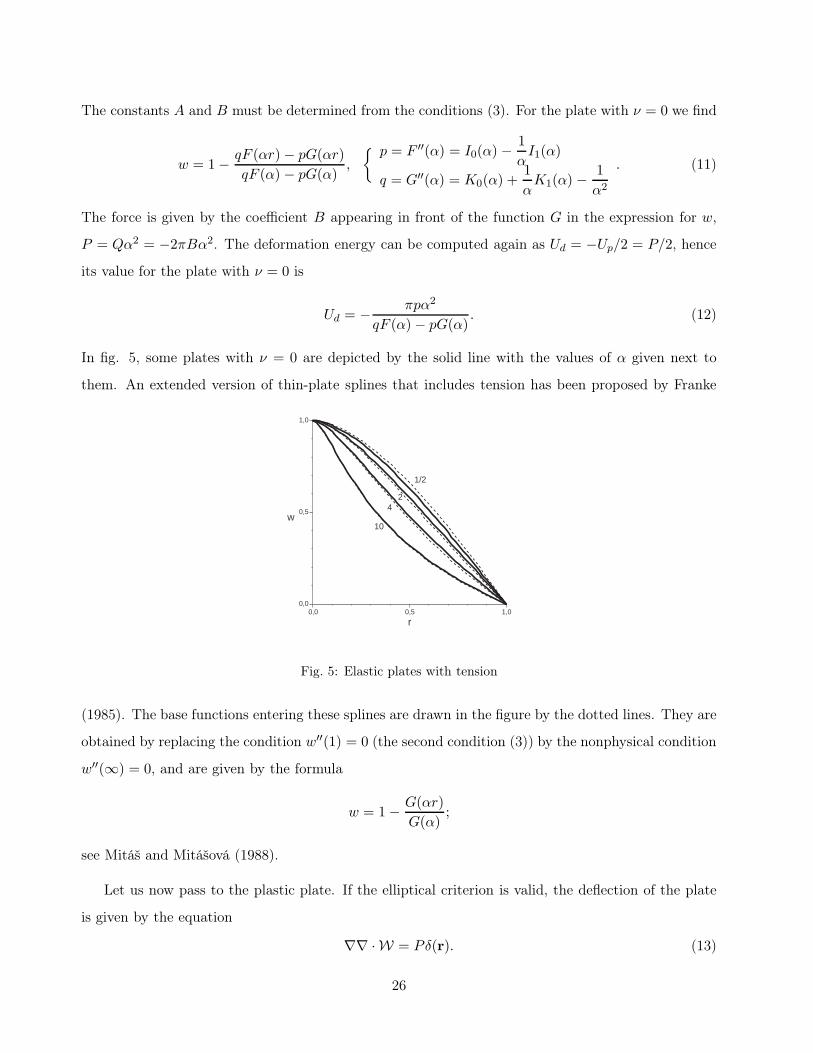
The constants A and B must be determined from the conditions (3). For the plate with ν = 0 we find
w = 1− qF (αr)− pG(αr)
qF (α) − pG(α),
{ p = F ′′(α) = I0(α) −1
αI1(α)
q = G′′(α) = K0(α) +1
αK1(α) −
1
α2
. (11)
The force is given by the coefficient B appearing in front of the function G in the expression for w,
P = Qα2 = −2πBα2. The deformation energy can be computed again as Ud = −Up/2 = P/2, hence
its value for the plate with ν = 0 is
Ud = − πpα2
qF (α)− pG(α). (12)
In fig. 5, some plates with ν = 0 are depicted by the solid line with the values of α given next to
them. An extended version of thin-plate splines that includes tension has been proposed by Franke
0,0 0,5 1,00,0
0,5
1,0
2
10
4
1/2
w
r
Fig. 5: Elastic plates with tension
(1985). The base functions entering these splines are drawn in the figure by the dotted lines. They are
obtained by replacing the condition w′′(1) = 0 (the second condition (3)) by the nonphysical condition
w′′(∞) = 0, and are given by the formula
w = 1− G(αr)
G(α);
see Mitáš and Mitášová (1988).
Let us now pass to the plastic plate. If the elliptical criterion is valid, the deflection of the plate
is given by the equation
∇∇ ·W = Pδ(r). (13)
26

If, moreover, the plate is simply supported, w obeys the same boundary conditions as before, with ν
replaced by κ. Consider w of the form
w = 1− rp. (14)
From the definition of W we obtain
W = const+Ann,
where n = r/r and A = (1− κ)(1 + q)/q, q = 1− p, q =√
q2 − 2κq + 1. This yields
∇∇ ·W = A
[
∂
∂x
(nx
r
)
+∂
∂y
(ny
r
)
]
= 2πAδ(r),
so that the ansatz (14) solves equation (13) if P = 2πA. From the second condition (3) with ν replaced
by κ we obtain
p = 1− κ, (15)
and if we insert this into the definition of A and use Ud = P = 2πA, we find
Ud = 2π√
1− κ2. (16)
For κ = 0 the plate has the shape of conus, and with increasing κ it bends inside. Note that the conus
is obtained also in the theory with the square criterion, see Kachanov (1956).
Solution (15) applies also to obliquely clamped plates which satisfy, in addition to the condition
w(1) = 0, the condition w′(1) = p with an arbitrary positive p. The shape of such plates is given
by equation (15) irrespective of their value of κ. This rises a question as to what is the shape of the
ordinary clamped plate that has w′(1) = 0. To answer that, introduce the function
ξ = limp→0+
(1− rp) ≈{
1 if r = 0
0 if 0 < r ≤ 1. (17)
The explicit expression for ξ is symbolic only, since the limit is understood in the weak sense, as an
operation to be performed after the rest of the computation has been completed. In particular, if
we define the integral norm of the function w(r) as the integral of the Frobenius norm of its Hessian
matrix,
‖w‖ =
∫ √trW 2dS = 2π
1∫
0
√
r2w′′2 + w′2dr,
we find that the norm of ξ is finite and equals 2√2π. In fact, we can define ξ by completing the space
of C2 functions with respect to the norm ‖.‖. With the function ξ at hand, we immediately solve the
27

problem with clamped plate we have started with. The deflection of the plate is w = ξ; that is, the
plate remains flat, only the point r = 0 is pulled out of it. The deformation energy is obtained most
easily from Ud = 2πA by inserting p = 0 into the formula for A. In this way we find
Ud = 2π√
2(1 − κ). (18)
The search for the solution describing an infinite plate leads to the conclusion that an infinite
plate fixed on the height 1 at r = 0 and on the height 0 at r = 1 has the deflection w = ξ∞ ≡ ξ
extended to all r. In fig. 6, the infinite rigid-plastic plate lifted at the center is depicted by the solid
line and by the black bullet on the vertical axis. To demonstrate the transition to such plate, several
0 1 2 3
0
1
Rcrit
r
w
Fig. 6: An infinite rigid-plastic plate
finite rigid-plastic plates with κ = 0 are shown in the figure, too, drawn by the dotted lines. The
curves were obtained by matching the solution (15) for r ≤ 1 with a quite intricate analytic solution
for r > 1. For the radius of the plate this procedure yields
R =
√1 + q
(1 + q2)1/4exp
(
1
2arctanq
)
.
If p decreases from 1 to 0, q increases from 0 to 1 and R increases from 1 to
Rcrit = 21/4eπ/8.= 1.76.
The radius Rcrit is depicted in the figure by the bullet on the horizontal axis. For R ≥ Rcrit the
deflection of the plate is w = ξR ≡ ξ extended to the radius R, so that the plate is represented by
the solid line cut at r = R and the bullet on the vertical axis. Finally, in fig. 7 several infinite
28

0 1 2 3
-1
0
1
1/5
1
20
w
r
Fig. 7: Infinite elastoplastic plates
elastoplastic plates with κ = 0 are shown, with the values of the ratio D/D given next to them.
The solution can be expressed in terms of a set of parameters that are fixed by a system of algebraic
equations. Deformation energy is 2π(q − βR2
plast/2), where β = D/D and Rplast is the radius of the
plastic domain in the central part of the plate.
IX. Conclusion
The mechanics of an elastic plate and the mechanics of a rigid-plastic plate with the elliptical
criterion look at first glance similar: the latter differs from the former just by the square root in
the expression for the deformation energy. However, this difference has far reaching consequences.
Analyzing the differential equation for deflection in the neighborhood of the δ-function source, one
finds that the elastic plate interpolates smoothly between the points at which it is fixed, while the
rigid-plastic plate has sharp vertices at these points. Moreover, the solution for a circular rigid-plastic
plate suggests that if the size of the plate exceeds some limit value, the forces fixing the plate at the
given set of points fail to deform the plate in the ordinary sense. The plate remains flat, and the forces
just pull the points out of it. Using the limit analysis it can be shown that if the plate is infinite, it
is not able to reach equilibrium but in this peculiar way.
The behavior of the plastic plate can be also compared to that of the plastic beam. Deformation
energy of the plastic beam is the total variation of deflection, which implies that the beam fixed at
the given set of points relaxes to a broken line. We can see that if we pass from one dimension to two,
the plastic behavior becomes more singular.
29

Acknowledgement. This work was initiated 11 years ago by Ivan Mizera, then professor of math-
ematical statistics at Comenius University, who was interested in mechanical motivations of some
techniques in mathematical statistics. I am grateful to him for many stimulating discussions a for his
hospitality during my one month stay at the University of Alberta. The stay was funded by the grant
VEGA 1/1008/09 and the NSERC of Canada.
References
R. Franke (1985), Comp. Aid. Geom. Des. 2, 87.
R. L. Harder and R. N. Desmarais (1972), J. Aircraft 9, 189.
R. Hill (1050): The Mathematical Theory of Plasticity, Oxford University Press, Oxford.
L. M. Kachanov (1956): Osnovy teorii plastichnosti, GITTL, Moscow; English translation: Funda-
mentals of the Theory of Plasticity, North-Holland Publishing Company, Amsterdam (1971).
L. D. Landau and Y. M. Lifshitz (1965): Teoria uprugosti, Moscow, Nauka; English translation:
Theory of Elasticity, Pergamon Press, Oxford (1975).
E. H. Mansfield (1957), Proc. Roy. Soc. A 241, 311.
L. Mitáš and H. Mitášová (1988), Comp. Mat. App 16, 983.
R. Temam (1983): Problémes mathématiques en plasticité, Gautier-Villars, Paris.
S. P. Timoshenko and S. Woinowsky-Krieger (1959): Theory of plates and shells, McGraw-Hill, New
York.
W. H. Yang (1980a, b), J. App. Mech. 47, 297, 301.
30