microcontroller based robotic arm
DESCRIPTION
Robotics has been a tremendous successful field ofresearch in last few decades. Regarding the development ofrobotics, many developed robotic arm has been deployed inindustrial purposes like automation, sophisticated fabrication etc.This paper is an initiative to patronize the robotic arm forhazardous situation people who can use his hand to move objectwithin certain range to carry out that job. This project is meantto designing and developing of a microcontroller (ATmega) basedrobotic arm. The project delivers a combined implementation ofElectrical, Electronic as well as Mechanical gen. The robotic armresponds to the gesture as well as can be programmed to go alonga definite path and task. The system senses the movement of user’s arm and roboticarm replicates the given input gesture. The gesture is sensed by anumber of potentiometers which are embedded onto a glove orother structural attachment. The movement in potentiometerdetermines the position for the servo motors driving the parts ofthe arm.TRANSCRIPT
7/21/2019 Microcontroller Based Robotic Arm
http://slidepdf.com/reader/full/microcontroller-based-robotic-arm 1/5
Microcontroller Based Robotic ArmOperational to Gesture and Automated Mode
Mohammad Javed Ansari, Ali Amir
Dept. of Electrical & Electronic EngineeringInt’l Islamic University Chittagong (IIUC)
Chittagong, Bangladesh
[email protected], [email protected]
Md. Ahsanul Hoque
Lecturer, Dept. of Electrical & Electronic EngineeringInt’l Islamic University Chittagong (IIUC)
Chittagong, Bangladesh
[email protected], [email protected]
Abstract —Robotics has been a tremendous successful field of
research in last few decades. Regarding the development of
robotics, many developed robotic arm has been deployed in
industrial purposes like automation, sophisticated fabrication etc.
This paper is an initiative to patronize the robotic arm for
hazardous situation people who can use his hand to move object
within certain range to carry out that job. This project is meant
to designing and developing of a microcontroller (ATmega) based
robotic arm. The project delivers a combined implementation of
Electrical, Electronic as well as Mechanical gen. The robotic arm
responds to the gesture as well as can be programmed to go along
a definite path and task.
The system senses the movement of user’s arm and robotic
arm replicates the given input gesture. The gesture is sensed by a
number of potentiometers which are embedded onto a glove or
other structural attachment. The movement in potentiometer
determines the position for the servo motors driving the parts of
the arm.
Keywords—Robotics; SCARA; DOF; ATmega;
I. I NTRODUCTION
In the modern world, robotics has become popular,useful, and has achieved great successes in several fields ofhumanity. Robotics has become very useful in medicine,education, military, research and mostly, in the world ofmanufacturing. It is a term that has since been used to refer toa machine that performs work to assist people or work thathumans find difficult or undesirable. Robots, which could bedestructive or non- destructive, perform tasks that would have
been very tedious for human beings to perform. They arecapable of performing repetitive tasks more quickly, cheaply,and accurately than humans. Robotics involves the integration
of many different disciplines, among them kinematics, signalanalysis, information theory, artificial intelligence, and
probability theory. These disciplines when applied suitably,lead to the design of a very successful robot.
The most common types of robot technology that haveevolved for different purposes are Robotic Arms. The Roboticarms are mechanically controlled devices designed to replicatethe movement of a human arm. These are used for liftingheavy objects and carrying out tasks that require extremeconcentration and expert accuracy. The design of a robot armcan vary depending on what it is intended to do. A Robotic arm
consists of the following elements- controller, robot arm, endeffector, drives, sensors; which are integrated together to forma whole that all contribute to making it properly function [1];Controllers-these are the main processors of the robotic armsand act as their brains. They can either act automatically as
programmed or allow for manual operation by outputting
instructions directly from a technician. Robot Arms-The arm isthe main section of the robotic arm and consists of three parts:the shoulder, elbow and wrist. These are all joints, with theshoulder resting at the base of the arm, typically connected tothe controller, and it can move forward, backward or spin. EndEffector-acts as the hand of the robotic arm. This part comes indirect contact with the material the robot is manipulating. Somevariations of an effector are a gripper, a vacuum pump,magnets, and welding torches. Drives - the mechanical systemsthat move the robotic arm into place [2]. The drives aretypically located between the joints and are responsible formotion and placement. Sensors-are used in advanced robots.Some are riddled with sensors that allow them to sense theirenvironment and react accordingly. Six major categories of
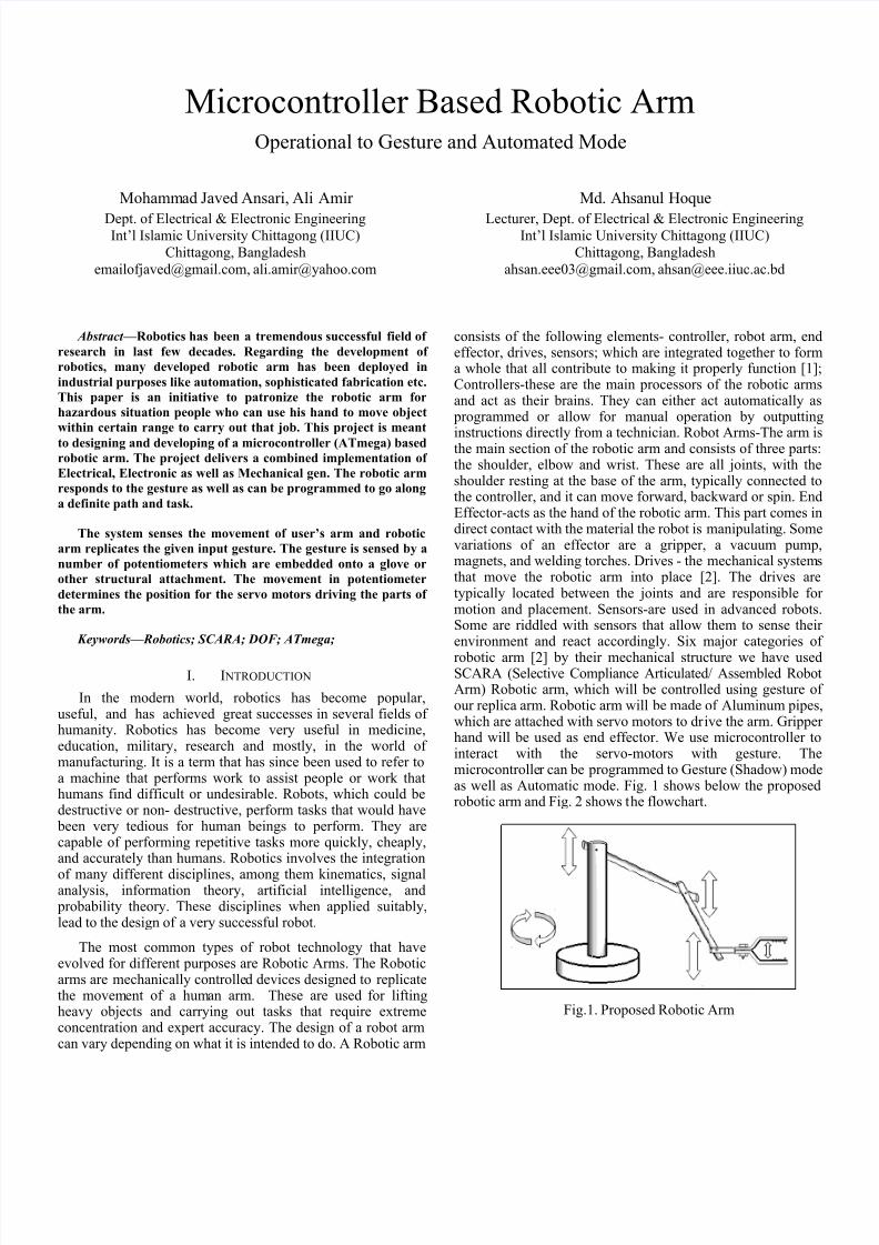
robotic arm [2] by their mechanical structure we have usedSCARA (Selective Compliance Articulated/ Assembled RobotArm) Robotic arm, which will be controlled using gesture ofour replica arm. Robotic arm will be made of Aluminum pipes,which are attached with servo motors to drive the arm. Gripperhand will be used as end effector. We use microcontroller tointeract with the servo-motors with gesture. Themicrocontroller can be programmed to Gesture (Shadow) modeas well as Automatic mode. Fig. 1 shows below the proposedrobotic arm and Fig. 2 shows the flowchart.
Fig.1. Proposed Robotic Arm
7/21/2019 Microcontroller Based Robotic Arm
http://slidepdf.com/reader/full/microcontroller-based-robotic-arm 2/5
Fig.2. Flowchart of the proposed robotic arm
In Fig. 2 the process starts with enabling the ADC (Analogto digital conversion) later the command flow line checks forthe mode selection by the user. Two modes can be selected,either Shadow Mode or Automatic mode.
Shadow Mode: In case the selection bit resembles shadowmode, every time the replica arm is moved the change in the
potentiometer position causes change in voltage levels whichthrough ADC is convert to certain ADC values. These ADCvalues are then interpreted by the MCU in terms of equivalentvarying pulses; PWM. Thus generated PWM can be fed to theservo motor control input which causes a desired deviation asthat of the replica arm. The servo movement can be calibratedto meet the replica arm movement finely.
Automatic Mode: The robotic arm when selected for automaticmode reads some predefined movement, interpreted in codes,which the robotic arm repeats on and on. The movements can
be coded as required.
II. CIRCUIT DIAGRAM & DESCRIPTION
SCARA robots have two parallel rotary joints to allow full
movement throughout a plane, typically for pick-and-place
work. From Fig. 2 we can understand there should be a smooth
and accurate signal transition throughout the whole operation
in order to pick-and-place work. The whole basic operation
will be conveying by our circuit based of microcontrollerATmega8A. This Atmel ATmega8A is capable of processing
16MIPS and consists of 6 ADC channels of 10-bit accuracy.
Movement of arm operated by motors especially servo
motors. Servomotors are generally used as a high performance
alternative to the stepper motor. Stepper motors have someinherent ability to control position, often allows them to be
used as an open-loop position control, without any feedback
encoder, as their drive signal specifies the number of steps of
movement to rotate. This lack of feedback though limits their
performance, as the stepper motor can only drive a load that is
well within its capacity, otherwise missed steps under load may
lead to positioning errors [3].
A. Control Circuit for Servo Motors
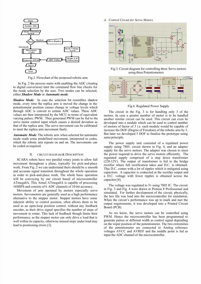
Fig.3. Circuit diagram for controlling three Servo motorsusing three Potentiometers
Fig.4. Regulated Power Supply
The circuit in the Fig. 3 is for handling only 3 of themotors. In case a greater number of motor is to be handledanother similar circuit can be used. This circuit can even bedeveloped into a module which can be used to control numberof motors of factor of 3 i.e. each module would be capable ofincrease the DOF (Degree of Freedom) of the robotic arm by 3.But later we developed 5 DOF to finalize the prototype usingsame principle.
The power supply unit consisted of a regulated powersupply using 7805, circuit shown in Fig. 4, and an adapter
supply for the servo motors. The adapter was chosen to meetthe power required to drive the servo motors efficiently. Theregulated supply comprised of a step down transformer(220:12V). The output of transformer is fed to the bridgerectifier where full rectification takes and D.C. is obtained.This D.C. comes with a lot of ripples which is mitigated usingcapacitors. A capacitor is connected at the rectifier output anda D.C. voltage with fewer ripples is obtained across thecapacitor [4].
The voltage was regulated to 5v using 7805 IC. The circuitin Fig. 3 and Fig. 4 were drawn in Proteus 8 Professional andsimulated. For further development of the circuit; physically,the hex file was load into the microcontroller for simulation.
When the circuit’s performance was up to mark and met theoutput requirements, it was developed into a Printed CircuitBoard (PCB).
As we know, the servo motors can be controlled usingPWM. Hence the microcontroller has been programmed togenerate pulses or different width as control signal dependingon the wiper position of the potentiometer. The two extremitiesof the potentiometer are connected to Analog referencevoltages AVCC and AVREF and the middle point is fed asinput the ADC channel of the microcontroller.

7/21/2019 Microcontroller Based Robotic Arm
http://slidepdf.com/reader/full/microcontroller-based-robotic-arm 3/5
TABLE I. Voltage Reference Selections for ADC
REFS1 REFS0 Voltage Reference Selection
0 0 AREF, internal Vref turned off
0 1 A Vcc with external capacitor at AREF pin
1 0 Reserved
1 1Internal 2.56V Voltage Reference with externalcapacitor at AREF pin
These bits select the voltage reference for the ADC, asshown in TABLE I. If these bits are changed during aconversion, the change will not go in effect until thisconversion is complete (ADIF in ADCSRA is set). The internalvoltage reference options may not be used if an externalreference voltage is being applied to the AREF pin.
B. Parallelogram joints & Counter Weight Determination
The limbs were coupled using the parallelogram technique.As shown in the Fig. 5 the rotating horn of the servo motorattached onto a limb was controlled the moved of other limbattached to it by means of two brackets, on either side of thehorn at equal distance i.e. ‘y’ from the center of horn. As in theFig. 5 Limb1 and Limb2 are pivoted and Limb2 hosts the servowith two parallel brackets joining Limb1. The brackets atLimb1 may be attached at distance equal to that of the horn i.e.x=y or it may differ. In case x>y, torque will be greater butdisplacement will be smaller while x<y displacement will begreater whereas torque will be reduced. We have chosen x=yfor all the joints except for that of base, where x>y. This has
been chosen so because the base bears the entire weight of the
arm which would require greater torque for movement.Initially, when the servo motor is at mean position, let
Limb1’s position be Position1. When the servo motor rotates,the upper and lower brackets displace equally but in oppositedirection. This cause a push-pull effect on Limb1 thus rotatingit by an equal angle of deflection by the servo horn andPosition2 is achieved. We chose this technique of coupling sothat the motors could be kept at a suitable place in order toreduce the lever-effect.
Fig.5. Parallelogram joints at different positions
Counter weight determination is important to grab anyobject by robotic arm. The slightest weight of motor and otherattachments on the extremities of the limbs could cause agreater torque, in short lever effect. In case this torque becomes
greater than the stall torque of the motor, the motor won’t beable to operate. Thus, cancellation of this opposing torque, for
better operation a counter weight needs to be added on theother end. This can be well understood from the followingillustration.
Fig.6. Counter weight determination
The counter weight can be easily determined. Suppose thedistance from the pivot to ‘Load’ be ‘Load Arm’ and ‘Effort’or counter weight be ‘Effort Arm’. Thus, use “(1)”to determinethe counter weight.
(1)
III. DEVELOPPED PROTOTYPE
Our developed prototype has 3 DOF at initial stage andlater it has to 5 DOF as mentioned earlier. So, the hex code wasmodified to suit the 5 Degree of Freedom for the arm. The codewas ciphered to hex and then burnt on the MCU chip usingAVRpal.NET and AVRDEV Tool. The finished prototypeappeared as like in Fig. 7. The arm was physical structure was
built using aluminum plates and pipes. The robotic arm wasable to work under both modes i.e. Gesture (Shadow) modereading the wooden replica arm and Automated mode.
Fig.7. Complete prototype with replica

7/21/2019 Microcontroller Based Robotic Arm
http://slidepdf.com/reader/full/microcontroller-based-robotic-arm 4/5
Fig.8. Replica Arm
A. Replica Arm
The replica arm was made up of wood which was hinged at joints by means of potentiometer. The potentiometers were fedto the ADC input lines. As the replica arm is moved the
potentiometer’s knob rotates resulting in change in the voltagelevels using voltage divider rule. The change in voltage level isread by the ADC channels as the change in ADC values. These
changes in the ADC values are read by the microcontroller andwhich eventually cause the change in the PWM pulse of theoutput. These varying pulse widths are fed to the servo motorswhich control the servo position. The replica arm is capable ofmaking the robotic arm work only in the Shadow mode.Meanwhile it is of no control in automatic mode. Thedeveloped replica arm is showing in Fig.8. Here we arementioning the parameter of the prototype:
Number of Axes: 3
Degree of freedom: 5
Power source: Electricity
End Effector Maxm Opening: 10 cm
Maxm Arm Stretch: 30 cm
Maxm Payload: 50gm
Type: SCARA (Selective Compliance Articulated/Assembled Robot Arm)
B. Discussion
• The finished project was capable of dealing with ademonstrating pay load. However this can be furtherdeveloped using servo motors of greater torque to meet
heavier demands. And the movement can be madesophisticated by simply adding greater number ofDegrees of Freedom, not to mention, which wouldcertainly approach with further problems to be takencare of. The output for the prototype was as proposedi.e. it was capable of working at both Shadow andAutomatic Mode.
C.
Shadow Mode OutputThe completed prototype of the robotic arm was able to
replicate the movement of the wooden replica. In case theshadow mode is not exact, it would require calibration with thegenerated ADC equivalent PWM signal. Using this modevarious tasks can be done. If the prototype is developed withwireless control it would help the bomb squad for bombdisbarment. Likewise, it can be used in rovers sent in spaceexpedition for sample collection and other jobs, etc.
D. Automatic Mode Output
When the mode selection switch was slide to the automaticmode the robotic arm would no more replicate the movement
of wooden replica. Rather, it would go on repeating the numberof instructions for definite positions; as coded into themicrocontroller. This mode can be programmed to be activatedat certain triggers such as when a finished product in a
production line reaches the end; the robotic arm can betriggered to transfer the product to the packaging zone.
E. Real-life Implementation aspect, complexity and study of
cost
The aim of this prototype was to handle situation like
human assignation is hazardous or accuracy of some task. For
example, bomb, explosive, mine or detonator now-a-days
handled by some squad where most of the times they need to
deactivate those dangerous things by hand. If we can use suchrobot, which can act like a human hand and can work through
remotely it can save life. From this point of view, this
prototype was developed and further improvement of this
robotic arm can be helpful in this area. Although, few bomb
disposal robot has been made already in different area of the
world, but here we have tried to make this prototype in a cost
effective way [5], [6]. Though this prototype was functional
but it had some inadequacies in reaching full swing of arm.
For this reason, it can’t give full value of DOF. As a result, for
practical implement this arm we need to use precision actuatorto avoid unwanted swing and movement. Gesture reading
position was not that interactive as expected and we can avoid
this complication using flex sensors or hall elements. But dueto cost minimization we did not used that. Now, the total cost
to make this prototype was almost 1200 BDT. But most of the
robotic arm (based on microcontroller) prototype developedaround the world is costly [5], [6], [7]. But the features of each
prototype are unique and specific object oriented. So, it is not
easily comparable all of them with respect to cost.
Nevertheless, based on approximation of these prototypes [5],
[6], [7] and our developed one is in minimum cost.

7/21/2019 Microcontroller Based Robotic Arm
http://slidepdf.com/reader/full/microcontroller-based-robotic-arm 5/5
IV. CONCLUTION
In this paper, we have developed a microcontroller basedrobotic arm where ADC conversion and PWM generation forcontrolling and two modes to operate that arm shadow orautomatic. As per the selected mode the further actions arecarried out. For the shadow mode the robotic arm replicate themovements of the Replica Arm and in Automatic mode, therobotic arm went on and on with the predefined steps. As the
project is based on gesture movement, with a proper blend ofAI (Artificial Intelligence) concepts and powerful componentsit may be developed into highly interactive robot.
ACKNOWLEDGMENT
We would like to thank all the teachers and technical stuffof our university for their unequaled support. We also thank toour friends to inspire us to finish this robotic arm. We aregrateful to our supervisor Mr. Ahsanul Hoque, Lecturer, EEE,IIUC for his continuous support and assistance in whole
project.
R EFERENCES
[1] Paul E. Sandin, “Robot Mechanisms and Mechanical Devices
Illustrated” chapter 7, pp-203.
[2] Jegede Olawale, Awodele Oludele, Ajayi Ayodele, “Development of a
Microcontroller Based Robotic Arm”, in Proceedings of the 2007
Computer Science and IT Education Conference pg: 549-557
[3] Theraja,B.L. and Theraja, A.K. “A Textbook of Electrical technology”
Vol.2, Chap. 39th, pp. 1562
[4] “Stepper Motor Control-AVR Tutorial”, Avinash, Extreme Electronics,May 20, 2011
[5] A. Rama Krishna, G. Sowmya Bala, A.S.C.S. Sastry, B. Bhanu
Prakash Sarma, Gokul Sai Alla “Design And Implementation Of A
Robotic Arm Based On Haptic Technology” IJERA, Vol. 2, Issue 3,
May-Jun 2012, pp.3098-3103.
[6] A. Che Soh, S.A. Ahmad, A.J. Ishak and K. N. Abdul Latif
“development of an adjustable gripper for robotic picking and placing
operation” international journal on smart sensing and intelligent
systems, vol. 5, no. 4, December 2012
[7] P.S.Ramaiah,M.Venkateswara Rao, G.V.Satyanarayana “A
Microcontroller Based Four Fingered Robotic Hand”- International
Journal of Artificial Intelligence & Applications (IJAIA), Vol.2, No.2,
April 2011