minimizing water intrusion through roof vents in … builder’s guide to coastal construction 7.5:...
TRANSCRIPT

Purpose: To describe practices for minimizing water intrusion through roof vent systems that can lead to interior damage and mold growth in high-wind regions (i.e., greater than 90-miles per hour [mph] basic [gust design] wind speed).1
HOME BUILDER’S GUIDE TO COASTAL CONSTRUCTION
7.5: MINIMIZING WATER INTRUSION THROUGH ROOF VENTS
1 of 8
HOME BUILDER’S GUIDE TO COASTAL CONSTRUCTION Technical Fact Sheet No. 7.5
RO
OF
ING 7
12/10
Minimizing Water Intrusion Through Roof Vents in High-Wind Regions
Key Issuesn Hurricane winds can drive large amounts of wa-
ter through attic ventilation openings. The ac-cumulating water soaks insulation and gypsum board, which can lead to mold growth and, in some cases, to the collapse of ceilings.
n Attic ventilation can be provided by a number of devices, most of which have been observed to al-low water intrusion under certain conditions and some of which have been observed to blow off. These devices include:n Soffit ventsn Ridge ventsn Gable end ventsn Off-ridge ventsn Gable rake ventsn Turbines
n Adequate ventilation of attics is generally re-quired to promote the health of wood structural members and sheathing in the attic.
n Attic ventilation can reduce the temperatures of roof coverings, which will typically prolong the life of the roof covering. However, roof color can have more of an impact on roof covering temperature than the amount of ventilation that is or is not provided.
n An unvented attic can be an effective way to prevent water intrusion and this type of attic is gaining popularity for energy efficiency reasons, provided the air conditioning system is sized ap-propriately. However, an unvented attic is best accomplished when it is specifically designed into the house and all of the appropriate details are handled properly. On an existing house, any
attempt to change to an unvented attic configu-ration needs to be done very carefully with the advice of knowledgeable experts. There are a number of changes that have to be made to pro-duce a successful transition from a ventilated to an unvented attic. One side effect of going to an unvented attic may be to void the warranty for the roof covering.
The following information is intended to help minimize water intrusion through new and existing attic ventila-tion systems, not to change from a ventilated to an unvented system. With the exception of the plugging of gable rake vents, all other shuttering of openings or plugging of vents should be done on a temporary basis and removed once the storm threat is over so that the attic is once again properly ventilated.
The Unvented AtticThe most conservative approach to prevent-ing wind-driven rain from entering the attic is to eliminate attic ventilation, but unvented at-tics are controversial. Although allowed by the International Residential Code (IRC), provided the Code’s criteria are met, unvented attics may not comply with local building codes.
However, when unvented attics are allowed by the building code or code compliance is not an issue, and when climatic and interior humidity conditions (e.g., no indoor swimming pools) are conducive to an unvented design, an unvented attic is a reli-able way to prevent wind-driven rain from entering the attic.
Air barrier: Refer to Fact Sheet 5.3, Siding Installa-tions in High-Wind Regions for recommendations regarding attic air barriers.
1 The 90 mph speed is based on ASCE 7-05. If ASCE 7-10 is being used, the equivalent wind speed is 116 mph for Risk Category II buildings

HOME BUILDER’S GUIDE TO COASTAL CONSTRUCTION
7.5: MINIMIZING WATER INTRUSION THROUGH ROOF VENTS IN HIGH-WIND REGIONS
2 of 8
RO
OF
ING
7
12/10
Mitigation Guidance
Soffit VentsKey Issuesn It is important to keep the soffit ma-
terial in place. While some water can be blown into the attic through almost any type of soffit vent, the amount of water intrusion increas-es dramatically when the soffit ma-terial is missing (Figure 1).
n Plywood or wood soffits are gener-ally adequately anchored to wood framing attached to the roof struc-ture and/or the walls. However, it has been common practice for vinyl and aluminum soffit panels to be in-stalled in tracks that are frequently very poorly connected to the walls and fascia at the edge of the roof overhang. When these poorly an-chored soffits are blown off, water intrusion increases significantly. Properly installed vinyl and alumi-num soffit panels are fastened to the building structure or to nailing strips placed at intervals specified by the manufacturer.
Proper Installation
The details of proper installation of vinyl and aluminum soffits depend on the type of eave to which they are at-tached. The key elements are illustrated in Figure 2.
Figure 1. Missing soffit material.
A. Roof truss or rafter framing should extend across the bottom of the eaves, or be add-ed to create a structural support for the soffit. As an alternative, soffits can be at-tached directly to the undersides of the an-gled rafters.
B. Nailing strips should be provided, if neces-sary, to allow attachment of the soffit at the ends. Intermediate nailing strips may be needed, depending on the maximum span permitted for the soffit. If this is not known, the span between attachment points should not exceed 12” in high-wind regions.
C. A J-channel (illustrated), F-channel, or oth-er receiver as specified by the manufactur-er should cover the ends of the soffit pan-els. Fasteners should be those specified by the manufacturer. Fasteners should be used through the nailing strip of each panel and at any other points (such as in the “valleys” of the soffit) if specified.
D. The overall span (eave depth) of the soffit should not exceed any limits specified by the manufacturer, and any required intermediate attachment points should be used.
Figure 2. Key soffit installation points.
B
A
C
D

HOME BUILDER’S GUIDE TO COASTAL CONSTRUCTION
7.5: MINIMIZING WATER INTRUSION THROUGH ROOF VENTS IN HIGH-WIND REGIONS
3 of 8
RO
OF
ING 7
12/10
Checking Soffit Material Installation
As previously noted, the most critical soffit installa-tions to check are those where vinyl or aluminum soffit panels are used. Soffits should be fastened to the eave structure; they should not be loose in the channels. Pushing up on the soffit material and the channels used to support the material can be reveal-ing. If it moves readily or is easy to deform, it probably is not attached very well. Similarly, if the width of the overhang is greater than 12 inches, there should be an intermediate support running along the middle of the soffit and the panels should be attached to this support in addition to the supports at the ends of the panels. If the reader is concerned about the installa-tion but cannot be sure, there are a couple of tools with a viewing screen connected to a small camera lens and light mounted at the end of a flexible tube that can be used to observe the connections. These devices allow inspection through a small hole that is drilled in an inconspicuous location that can be later filled with sealant. In order to ensure that there is a strong connection at the wall, there should be wood blocking running along the wall above the track where the soffit channel is attached and the channel should be fastened to that blocking. If there is no wood blocking, and there is either no vertical nailing surface on the channel or occasional tabs that have been cut and bent up to allow fastening to the wall, strengthening of the anchorage of the soffit material is clearly indicated.
Remedial Measures
If the inspection indicates a poorly attached soffit, the best way to ensure that the soffit material is ad-equately anchored in place is to remove it and install adequate wood blocking to allow solid anchorage of the soffit material. In some cases, it may be possible to remove the soffit material and reinstall it. However, it is also likely that some or all of the material will need to be replaced, so make sure that it can be matched before it is removed. Short of removing and properly reinstalling the soffit material, testing has shown that the anchorage can be greatly improved by applying a bead of sealant (Figure 3) along the bottom edge of the wall channel to adhere it to the wall surface below followed by applying large dabs of sealant in indentations between the soffit panels and the wall channel at one end (Figure 4) and the fascia flashing at the other end. Surfaces receiving sealant should be cleaned in order to facilitate bonding. Extra resistance can be gained by installing screws that mechanically tie the soffit panels to both the fascia flashing and to the wall channel (Figure 5). Note that use of sealant is a remedial measure only and is not a substitute for proper installation and fastening of soffits in a new installation.
Figure 3. Applying a bead of sealant. (Note: Black sealant was used so that it would be visible in the photograph. Normally a matching sealant color would be used.)
Figure 5. Screws through wall channel.
Figure 4. Applying dabs of sealant.
HOME BUILDER’S GUIDE TO COASTAL CONSTRUCTION
7.5: MINIMIZING WATER INTRUSION THROUGH ROOF VENTS IN HIGH-WIND REGIONS
4 of 8
RO
OF
ING
7
12/10
Wind-driven rain penetration: Currently there is no ade-quate standard test method to evaluate the potential for wind-driven rain to enter attics through soffit vent openings, such as those shown in Figure 6. To avoid water entry at soffit vents, options include eliminat-ing soffit vents and providing an alternate method for air to enter the attic, or design for an unvented attic. Another approach is to place filter fabric (like that used for heating, ventilation, or cooling [HVAC] sys-tem filters) above the vent openings; however, such an approach needs to be custom designed.
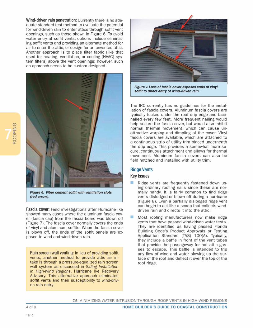
Fascia cover: Field investigations after Hurricane Ike showed many cases where the aluminum fascia cov-er (fascia cap) from the fascia board was blown off (Figure 7). The fascia cover normally covers the ends of vinyl and aluminum soffits. When the fascia cover is blown off, the ends of the soffit panels are ex-posed to wind and wind-driven rain.
The IRC currently has no guidelines for the instal-lation of fascia covers. Aluminum fascia covers are typically tucked under the roof drip edge and face-nailed every few feet. More frequent nailing would help secure the fascia cover, but would also inhibit normal thermal movement, which can cause un-attractive warping and dimpling of the cover. Vinyl fascia covers are available, which are attached to a continuous strip of utility trim placed underneath the drip edge. This provides a somewhat more se-cure, continuous attachment and allows for thermal movement. Aluminum fascia covers can also be field notched and installed with utility trim.
Ridge VentsKey Issuesn Ridge vents are frequently fastened down us-
ing ordinary roofing nails since these are nor-mally handy. It is fairly common to find ridge vents dislodged or blown off during a hurricane (Figure 8). Even a partially dislodged ridge vent can begin to act like a scoop that collects wind-driven rain and directs it into the attic.
n Most roofing manufacturers now make ridge vents that have passed wind-driven water tests. They are identified as having passed Florida Building Code’s Product Approvals or Testing Application Standard (TAS) 100(A). Typically, they include a baffle in front of the vent tubes that provide the passageway for hot attic gas-ses to escape. This baffle is intended to trip any flow of wind and water blowing up the sur-face of the roof and deflect it over the top of the roof ridge.
Figure 6. Fiber cement soffit with ventilation slots (red arrow).
Figure 7. Loss of fascia cover exposes ends of vinyl soffit to direct entry of wind-driven rain.
Rain screen wall venting: In lieu of providing soffit vents, another method to provide attic air in-take is through a pressure-equalized rain screen wall system as discussed in Siding Installation in High-Wind Regions, Hurricane Ike Recovery Advisory. This alternative approach eliminates soffit vents and their susceptibility to wind-driv-en rain entry.

HOME BUILDER’S GUIDE TO COASTAL CONSTRUCTION
7.5: MINIMIZING WATER INTRUSION THROUGH ROOF VENTS IN HIGH-WIND REGIONS
5 of 8
RO
OF
ING 7
12/10
Checking Ridge Vents and Their Installation
When they are used, ridge vents are the last part of the roof to be installed. Consequently, the con-nection is readily accessible and frequently visible without having to pry up the edge of the vent cover top. Check the type and condition of the fasteners. If the fasteners are nails, replacement of the fasteners is in order. If the vent has clear holes or slots without any baffle or trip next to the edge of the vent chan-nels, the vent is probably not one that is resistant to water intrusion and you should consider replacing the ridge vent with one that has passed the wind-driven water intrusion tests.
Remedial Measures
Replace nails with gasketed stainless steel wood screws that are slightly larger than the existing nails and, if possible, try to add fasteners at locations where they will be embedded in the roof structure be-low and not just into the roof sheathing. Close spacing of fasteners is recommended (e.g., in the range of 3 to 6 inches on center, commensurate with the design wind loads). If the ridge vents are damaged or are one of the older types that are not resistant to water in-trusion, they should be replaced with vents that have passed the wind-driven water intrusion tests.
Gable End VentsKey Issuesn Virtually all known gable end vents (Figure 9) will
leak when the wall they are mounted on faces into the wind-driven rain. The pressures devel-oped between the outside surface of the wall and the inside of the attic are sufficient to drive water uphill for a number of inches and, if there is much wind flow through the vent, water carried by the wind will be blown considerable distances into the attic.
Figure 9. Gable end vent.
Figure 8. This metal ridge vent was attached with widely spaced roofing nails.
Slotting the Deck
When ridge venting is being added to a roof that previously did not have it, it is necessary to cut a slot through the decking. When doing so, it is important to set the depth of the saw blade so that it only slightly projects below the bottom of the decking. At the residence shown in Figure 8, the saw blade cut approximately 1 1/2 inches into the trusses and cut a portion of the truss plate (red arrow).

HOME BUILDER’S GUIDE TO COASTAL CONSTRUCTION
7.5: MINIMIZING WATER INTRUSION THROUGH ROOF VENTS IN HIGH-WIND REGIONS
6 of 8
RO
OF
ING
7
12/10
Remedial Measures
If it is practical and possible to shutter gable end vents from the outside of the house, this is the pref-erable way to minimize water intrusion through gable end vents (Figure 10). Install permanent anchors in the wood structure around the gable vent and precut, pre-drill, and label plywood or other suitable shutter materials so that they are ready for installation by a qualified person just before a storm approaches. If installation of shutters from the outside is diffi-cult because of the height or other considerations, but there is access through the attic, the gable vent opening can be shuttered from the inside. However, careful attention needs to be paid to sealing around the shutter and making sure that any water that accu-mulates in the cavity can drain to the outside of the house and not into the wall below.
Off-ridge VentsKey Issues
Poorly anchored off-ridge vents can flip up and be-come scoops that direct large amounts of wind-driven rain into the attic (Figure 11).
Some vents are also prone to leaking when winds blow from certain directions. This will depend on the location of the vent on the roof surface and the ge-ometry of the roof, as well as the geometry of the particular vent.
Checking Off-Ridge Vent Installations
Off-ridge vents typically have a flange that lies against the top surface of the roof sheathing and is used to anchor the vent to the roof sheathing. Frequently, roofing nails are used to attach the flange to the roof sheathing. The off-ridge vents should be checked to make sure that they are well anchored to the roof sheathing. If they seem loose, or there are not many fasteners holding them down, it could be a weak link
in preventing water intrusion when a storm occurs. Since the flange and fasteners are hidden below the roof covering, it is not possible to simply add nails or screws to improve the anchorage as these will create holes through the roof covering.
Remedial Measures
If the off-ridge vent is attached to the roof sheathing with long, thin nails, it may be possible to improve the anchorage by cinching the nails (bending them over against the underside of the roof sheathing). However, if they are short and/or thick, trying to bend them over may cause more harm than good. Some homeowners have had covers made that can be installed from the inside of the attic over the hole where the off-ridge vent is installed. This will be easi-est if the vent is larger than the hole and the cover can be attached to the sheathing in an area where the fasteners cannot be driven through the roof cov-ering. Otherwise, it will be important to ensure that the fasteners are short enough that they will not ex-tend through the roof sheathing and damage the roof cover. If the edge of the hole in the roof deck is flush with the inside edge of the vent, it may be possible to install metal straps that are screwed into the walls of the vent and attached with short screws to the bot-tom surface of the roof sheathing. Again, it is critical to use screws that are short enough that they will not extend through the roof sheathing and damage the roof covering. The strapping should be connected to the walls of the vent with short stainless steel sheet metal screws.
Figure 10. Shuttered gable end vent.
Figure 11. Two off-ridge vents are shown in this photograph. The vent that is covered with roofing felt flipped up and allowed a substantial amount of water to enter the residence. Carpeting, kitchen cabinets, and a large amount of gypsum board had to be re-placed because of the water intrusion.

HOME BUILDER’S GUIDE TO COASTAL CONSTRUCTION
7.5: MINIMIZING WATER INTRUSION THROUGH ROOF VENTS IN HIGH-WIND REGIONS
7 of 8
RO
OF
ING 7
12/10
Gable Rake VentsKey Issuesn Gable rake vents are formed when porous soffit
panels or screen vents are installed on the bot-tom surface of the roof overhang at the gable end and there is a clear path for wind to blow into the attic. This usually happens when the gable overhang is supported by what are called outriggers. Outriggers are typically used when gable overhangs exceed 12 inches. In these cases, the last roof truss or rafter (the gable end truss or rafter) is smaller than the trusses or rafters at the next location inside the attic. Outriggers (2x4s) are installed over top of the last gable truss or rafter, one end is anchored to the second truss or rafter back from the ga-ble end, and the other end sticks out past the gable end wall to support the roof sheathing on the overhang.
Finding Out if You Have Gable Rake Vents and Whether You Still Need Them
The easiest way to tell if the roof has gable rake vents is to look in the attic on a cool sunny day and see if light is visible in gaps just below the sheath-ing at the gable end. The presence of the outriggers (2x4s running perpendicular to the gable truss and disappearing into the gable overhang) should also be visible. If there is also a gable end vent or a ridge vent, then the gable rake vent will probably not be needed in order to provide adequate venting for the attic.
Remedial Measures
The best solution if venting provided by the gable rake vents is not needed is to simply plug them up with metal flashing (Figure 12) or pieces of wood that are cut and anchored. They should be well attached and completely seal as many of the openings as possible
and particularly those near the gable peak. Sealant can be used to seal around the edges of the metal or wood plugs.
TurbinesKey Issuesn The rotating top portion of many turbines is not
designed to withstand high-wind conditions and they are frequently installed with just a friction fit to the short standpipe that provides the venting of the attic. It is possible to find high-wind rated turbines on store shelves in hurricane-prone re-gions but, in hurricane winds, the turbines will be rotating at tremendous speeds and can be easi-ly damaged by windborne debris.
n The flange on the standpipe that provides the connection of the pipe to the roof sheathing may also be poorly anchored to the roof sheathing.
Checking Turbines and Their Installation
Check any turbines to make sure that the stand pipes are not loose and that the turbine head is anchored to the stand pipe by sheet metal screws and not sim-ply by a friction fit (Figure 13).
Remedial Measures
Loose standpipes should be securely anchored to the roof sheathing. If the standpipe is attached to the roof sheathing with long, thin nails, it may be pos-sible to improve the anchorage by cinching the nails (bending them over against the underside of the roof sheathing). However, if they are short and/or thick, trying to bend them over may cause more harm than good. Some homeowners have had covers made that can be installed from the inside of the attic over the
Figure 12. Metal plugs (red arrows) in gable rake vents.
Figure 13. This turbine head is attached to the standpipe with dimple punches. Sheet metal screws should be added to strengthen the connection.

HOME BUILDER’S GUIDE TO COASTAL CONSTRUCTION
7.5: MINIMIZING WATER INTRUSION THROUGH ROOF VENTS IN HIGH-WIND REGIONS
8 of 8
RO
OF
ING
7
Developed in association with the National Association of Home Builders Research Center
12/10
hole where the standpipe is installed. This will be easiest if the standpipe is larger than the hole and the cover can be attached to the sheathing in an area where the fasteners cannot be driven through the roof cover. Otherwise, it will be important to ensure that the fasteners are short enough that they will not extend through the roof sheathing and damage the roof cover.
If the edge of the hole in the roof deck is flush with the inside edge of the standpipe, it may be possible to install metal straps that are screwed into the walls of the standpipe and attached with short screws to the bottom surface of the roof sheathing. Again, it is critical to use screws that are short enough that they will not extend through the roof sheathing and damage the roof cover. The strapping should be connected to the walls of the standpipe with short stainless steel sheet metal screws.
Beyond any remedial measures taken to anchor the standpipe to the roof sheathing or to plug the hole from the attic side, it is also important to try and seal the standpipe from the outside so that water does not build up in the pipe and leak into the roof sheathing around the hole. The best approach is to have a qualified person remove the top active por-tion of the turbine vent before the storm and plug the hole at the top of the standpipe. A wooden plug can be used that covers the entire hole and has blocks that rest against the walls of the standpipe where screws can be installed to anchor the plug to the standpipe. Some homeowners have had the entire turbine wrapped in plastic to keep water out during a storm (Figure 14). This can work as long as the tur-bine or wrapping does not get dislodged. The smaller area provided by removing the turbine top and plug-ging the hole is considered preferable.
Figure 14. Plastic wrapped turbines.