mitigation of weather radar disturbance caused by wind ... · caused by wind turbines challenges...
TRANSCRIPT
MITIGATION OFWEATHER RADAR DISTURBANCESCAUSED BY WIND TURBINES
Challenges for the Coexistence of Wind Farms and Radar and Navigation Systems in Germany and France
29.09.2015, Berlin, Germany
Frank Gekat, Gerd Teschke*, Ronald Hannesen*UAS Neubrandenburg

ABOUT SELEX ES GMBH
© 2015 Selex ES GmbH – Company confidential 2
Owned by Selex ES SpA, a division of FinmeccanicaSpA
Business fields: Meteorological radars and sensors systems Logisitic support for military radars Logisitc support for defence communication
Sites in Neuss and Backnang 200 employees (Met sensors: 140) 400 weather radars in 76 countries worldwide Combined revenue 2014: 55 Mio Euro

ORGANISATION
© 2015 Selex ES GmbH – Company confidential 3
Specific features of a weather radar
Interaction between weather radar and wind turbine
Wind turbine clutter suppression by interpolation
Retrieval by inverse sampling (RIS)
Wind turbine clutter suppression by signature subtraction
Gap filler radar
Conclusions

RADAR AND WEATHER RADAR
© 2015 Selex ES GmbH – Company confidential 4
RADAR = Radio Detection and RangingThe task of almost any radar is the detection of a target in a certain range cell (range gate). In the end this is a binary decision: Yes or No.
The task of a weather radar is the measurement of: Signal amplitude (power) in horizontal and vertical polarization from -110 dBm to -
10 dBm (10 fW – 10 mW) Signal phase in horizontal and vertical polarization from 0° to 360°
This corresponds to Rain rates (Reflectivity) from almost fog (-40 dBZ) up to hail (60 dBZ or
200 mm/hr) Radial wind velocities from 0 m/s up to 25 m/s (90 km/h or 10 Bft)
Derived moments like Differential reflectivity Differential phase Polarization correlation coefficient Linear depolarization ratio etc

RADAR AND WEATHER RADAR
© 2015 Selex ES GmbH – Company confidential 5
Z- and V CAPPI of a weather radar
PPI of a „detection“ radar.The dots are detected targets

THE ANTENNA – EYE OF A WEATHER RADAR
© 2015 Selex ES GmbH – Company confidential 6
Azimuth & elevation beam width: 0.5° - 1° Azimuth rotation rate: 2 – 6 rpm Elevation step: 2° in 2 sec
Range gate size (Az x El x Range) 1km: 16 m* x 16 m x 150 m** 100km: 1.7 km* x 1.7 km x 150 m
*1° beam width**depending on transmitter pulse width

ILLUMINATION OF A WT BY A WEATHER RADAR
© 2015 Selex ES GmbH – Company confidential 7
Tower and nacelle are not moving and can be filtered by conventional clutter filtering techniques
The blades are generating a broad velocity spectrum because the phase shift of the reflections from the blade tips is much larger than the phase shift from the hub flanges
ILLUMINATION OF A WT BY A WEATHER RADAR
© 2015 Selex ES GmbH – Company confidential 8
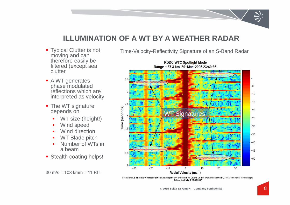
Typical Clutter is not moving and can therefore easily be filtered (except sea clutter
A WT generates phase modulated reflections which are interpreted as velocity
The WT signature depends on• WT size (height!)• Wind speed• Wind direction• WT Blade pitch• Number of WTs in
a beam Stealth coating helps!
30 m/s = 108 km/h = 11 Bf !
Time-Velocity-Reflectivity Signature of an S-Band Radar
WT Signatures

3D VOLUME SCANNING OF A WEATHER RADAR
© 2015 Selex ES GmbH – Company confidential 9
Volume Scan Pattern
Because the WT blades are strong scatterers, interference is also generated by the side lobes of the radar antenna

WT CLUTTER SUPPRESSION BY INTERPOLATION
© 2015 Selex ES GmbH – Company confidential 10
The range gates covering WTs are flagged in the radar clutter map. The information may be gathered by automatic detection during scanning or during the WT construction approval procedure
The radar detects whether a WT is rotating or not
If it is rotating, the flagged range gates will be discarded
The discarded range gates are then interpolated using the data of the neighboring range gates
The interpolation algorithm (linear, quadratic, cubic, spline etc.) may be selected by the user
If only a single isolated range gate is contaminated a dedicated speckle filter algorithm will be applied
Clutter Map Initialization
(WT Range Gates Flagged!)
WT Rotating? Spectral Clutter Filtering
Discard Data ofWT Range Gates
Interpolation ofWT Range Gates
Yes
Ingestion of Interpolated Data
No

INTERPOLATION – EXAMPLE VOLLRATHER HÖHE
© 2015 Selex ES GmbH – Company confidential 11
Wind Turbine Park Vollrather Höhe, 12 km Southeast of Selex ES NeussTotal Area: approx. 1.1 x 1.1 kmWind Turbines:
Qty. Type Rotor Dia. TowerHeight
PeakHeight
4 Tacke TW 600 43 m 50 m 93 m
9 AN Bonus 1000/54 60 m (? 50 – 70 m) 54 m 114 m (?)
1 Enercon E-82 E2 80 m (? 70 – 140 m) 82 m 162 m (?)

INTERPOLATION – EXAMPLE VOLLRATHER HÖHE
© 2015 Selex ES GmbH – Company confidential 12
WTs (Shadows)
Vollrather Höhe

INTERPOLATION – EXAMPLE VOLLRATHER HÖHE
© 2015 Selex ES GmbH – Company confidential 13
Without Interpolation With Signal Removal and Interpolation

INTERPOLATION – EXAMPLE VOLLRATHER HÖHE
© 2015 Selex ES GmbH – Company confidential 14
Without Interpolation With Signal Removal and Interpolation
Interpolation may cause artefacts!

EXTREME INTERFERENCE
© 2015 Selex ES GmbH – Company confidential 15
Source:Vogt, R.J.; Crum, T.; Burgess, D.W; Paese, M.S.: "An Update On Policy Considerations Of Wind Farm Impacts On WSR-88D Operations", 24th Conf. on Interact. Inf. Proc. Sys. (IIPS), 88th AMS Annual Meet, 20-24 Jan 2008, New Orleans, LA WT park with approx. 80 WTs!
Only the borderline WTs are marked.
Multipath scattering (scattering between WTs) Contamination of range gates behind the WT park
NEXRAD KTYX Radar, 10 March 2007
No Weather!

EXTREME INTERFERENCE
© 2015 Selex ES GmbH – Company confidential 16
NEXRAD KTYX Radar, 10 March 2007
Reflectivity PPI Radial Velocity PPI

RETRIEVAL BY INVERSE SAMPLING (RIS)
© 2015 Selex ES GmbH – Company confidential 17
Basic idea: space and time-dependent data are transformed into a suited transformation domainExample Fourier Transformation: A confusing time series is represented by a few Fourier coefficients.There are many other transforms which are much better suited for the transformation of weather radar data. A Wavelet representation is a very promising candidate.
Basic procedure:1) Data are analyzed for suited wavelet2) Sampled Data are transformed into the corresponding wavelet domain, with
particular emphasis to the spatial and temporal neighborhood of the discarded regions
3) Discarded data are reconstructed in wavelet domain during the iterative recovery process (inverse sampling). The underlying assumption is that the neighboring wavelet basis atoms extend into the discarded regions
4) The final reconstructed data in its spatio-temporal representation are obtained due to the inverse wavelet transformation

RIS EXAMPLE – DISCARDING A 5° SECTOR
© 2015 Selex ES GmbH – Company confidential 18
IQ-Amplitude PPI IQ-Amplitude PPI, 5° Sector discarded

RIS EXAMPLE – DISCARDING A 5° SECTOR
© 2015 Selex ES GmbH – Company confidential 19
IQ-Amplitude PPI IQ-Amplitude PPI, 5° Sector reconstructed

RIS – FURTHER RESEARCH
© 2015 Selex ES GmbH – Company confidential 20
First steps:1) Spatial data reconstruction2) Spatial and temporal data reconstruction
Open questions: Inverse sampling of I/Q data or moments, or both? Which wavelets are best suited for what data? Adaptive matching of wavelets to actual meteorological situation?
WT CLUTTER SUPPRESSION BY SIGNATURE SUBTRACTION
© 2015 Selex ES GmbH – Company confidential 21
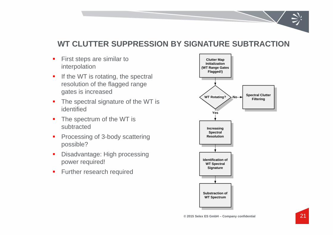
First steps are similar to interpolation
If the WT is rotating, the spectral resolution of the flagged range gates is increased
The spectral signature of the WT is identified
The spectrum of the WT is subtracted
Processing of 3-body scattering possible?
Disadvantage: High processing power required!
Further research required
Clutter Map Initialization
(WT Range Gates Flagged!)
WT Rotating? Spectral Clutter Filtering
Increasing Spectral
Resolution
Identification of WT Spectral
Signature
Yes
Substraction of WT Spectrum
No

WT CLUTTER SUPPRESSION BY SIGNATURE SUBTRACTION TWO EXAMPLES
© 2015 Selex ES GmbH – Company confidential 22
Upper diagrams: Before processing
Lower diagrams: after signature subtraction

GAP FILLER RADAR
© 2015 Selex ES GmbH – Company confidential 23
Advantages Provides accurate high-resolution real-time data Can be installed at any time, e.g. if unexpected problems should arise Provides seamless data coverage up to 10 - 20 km May provide additional information for the operation of the windpark (wind speed
and direction)
Challenges Experience with integration is missing, e.g. what is the required height? X-Band data must be integrated in C-Band data
Disadvantages Cost ( tower, radar, data link)

GAP FILLER RADAR EXAMPLE
© 2015 Selex ES GmbH – Company confidential 24

CONCLUSIONS
© 2015 Selex ES GmbH – Company confidential 25
WTs and weather radars are responding to basic demands of the society (severe weather alerting and management, regenerative energy generation without CO2emissions
Methods for mitigation of weather radar disturbance caused by WTs are available but limited in performance or expensive
Advanced methods promising a significantly higher performance level are proposed but need to be developed
There will always be a minimum distance between radar and WT!
A tool for the realistic prediction of the impact of a potential windfarm to the data quality of weather radars featuring dedicated mitigation method must be developed. This tool may be applied by the windfarm planners before submitting a building application, by the weather service or by the responsible public authorities during a windfarm approval procedure.
We are looking for partners which are interested in developing the methods presented in this talk to an operational level

Selex ES GmbHRaiffeisenstrasse 1041470 Neuss, GermanyTel: +49 (0) 2137 782-0 www.selex-es.de
Dr. Frank [email protected]
Thank you for your attention – any questions?