m_nokhodchian @ yahoo.com microprocessors 1-1 i/o devices peripheral devices (also called i/o...
TRANSCRIPT

M_nokhodchian @ yahoo.comM_nokhodchian @ yahoo.com MicroprocessorsMicroprocessors 1-1-11
I/O devices
Peripheral devices (also called I/O devices) are pieces of equipment that exchange data with a CPU
Examples: switches, LED, CRT, printers, keyboard, keypad
Speed and characteristics of these devices are very different from that of CPU so they cannot be connected directly
Interface chips are needed to resolve this problem Main function of an interface chip is to synchronize
data transfer between CPU and I/O device Data pins of interface chip are connected to CPU data
bus and I/O port pins are connected to I/O device

M_nokhodchian @ yahoo.comM_nokhodchian @ yahoo.com MicroprocessorsMicroprocessors 1-1-22
I/O devices
Since a CPU may have multiple I/O devices, CPU data bus may be connected to data buses of multiple interface
An address decoder is used to select one device to respond to the CPU I/O request
Different CPUs deal with I/O devices differently Some CPUs have dedicated instructions for performing
input and output operations (isolated I/O) Other CPUs use the same instruction for reading from
memory and reading from input devices, as well as writing data into memory and writing data into output devices (memory-mapped I/O)
MCS-51 (8051) is memory mapped

M_nokhodchian @ yahoo.comM_nokhodchian @ yahoo.com MicroprocessorsMicroprocessors 1-1-33
Synchronization of CPU and interface chip
There must be a mechanism to make sure that there are valid data in the interface chip when CPU reads them
Input synchronization: two ways of doing this1. Polling method
interface chip uses a status bit to indicate if it has valid data for CPU
CPU keeps checking status bit until it is set, and then reads data from interface chip
Simple method, used when CPU has nothing else to do
2. Interrupt driven method: interface chip interrupts the CPU when it has new data. CPU executes the ISR

M_nokhodchian @ yahoo.comM_nokhodchian @ yahoo.com MicroprocessorsMicroprocessors 1-1-44
Synchronization of CPU and interface chip
Output synchronization: two ways of doing this1. Polling method
interface chip uses a status bit to indicate that the data register is empty
CPU keeps checking status bit until it is set, and then writes data into interface chip
2. Interrupt driven method: interface chip interrupts the CPU when it data register is empty. CPU executes the ISR

M_nokhodchian @ yahoo.comM_nokhodchian @ yahoo.com MicroprocessorsMicroprocessors 1-1-55
Synchronization of CPU and interface chip
Methods used to synchronize data transfer between interface chip and I/O devices:
1. Brute force method: interface chip returns voltage levels in its input ports to CPU and makes data written by CPU directly available on its output ports All 8051 port can perform brute force I/O
2. Strobe method: During input, the I/O device activates a strobe signal when data
are stable. Interface chip latches the data For output, interface chip places output data on output port.
when data is stable, it activates a strobe signal. I/O device latches the data
3. Handshake method: two handshake signals are needed One is asserted by interface chip and the other by I/O device

M_nokhodchian @ yahoo.comM_nokhodchian @ yahoo.com MicroprocessorsMicroprocessors 1-1-66
8051 ports

M_nokhodchian @ yahoo.comM_nokhodchian @ yahoo.com MicroprocessorsMicroprocessors 1-1-77
8051 ports Ports 1, 2, and 3 have internal pullups, and
Port 0 has open drain outputs.
To be used as an input, the port bit latch must contain a 1, which turns off the output driver FET.
For Ports 1, 2, and 3, the pin is pulled high by a weak internal pullup, and can be pulled low by an external source.
Port 0 differs in that its internal pullups are not active during normal port operation (writing a 1 to the bit latch leaves both output FETs off, so the pin floats).

M_nokhodchian @ yahoo.comM_nokhodchian @ yahoo.com MicroprocessorsMicroprocessors 1-1-88
8051 I/O Ports: Hardware Specs
P0 is open drain.Has to be pulled high by external 10K
resistors.Not needed if P0 is used for address lines
P1, P2, P3 have internal pull-upsPort fan- out (number of devices it can
drive) is limited.Use buffers (74LS244, 74LS245,etc) to
increase drive.
P1, P2, P3 can drive up to 4 LS-TTL inputs

M_nokhodchian @ yahoo.comM_nokhodchian @ yahoo.com MicroprocessorsMicroprocessors 1-1-99
8051 - Switch On I/O Ports
Case-1: Gives a logic 0 on switch close Current is 0.5ma on switch
close
Case-2: Gives a logic 1 on switch close High current on switch close
Case-3: Can damage port if 0 is output

M_nokhodchian @ yahoo.comM_nokhodchian @ yahoo.com MicroprocessorsMicroprocessors 1-1-1010
Simple input devices DIP switches usually have 8 switches
Use the case-1 from previous page
Sequence of instructions to read a value from DIP switches:
mov P1,#FFH
mov A,P1,

M_nokhodchian @ yahoo.comM_nokhodchian @ yahoo.com MicroprocessorsMicroprocessors 1-1-1111
Interfacing a Keypad A 16-key keypad is built as shown in the figure below.
16 keys arranged as a 4X4 matrix.
Must “activate” each row by placing a 0 on its R output.Then the column
output is read. If there is a 0 on
one of the column bits, then the button at the column/row intersection has been pressed.
Otherwise, try next row. Repeat constantly
C 1C 2C 3C 4
R 1R 2R 3
R 4
0123
567
DEF
9AB
C
8
4

M_nokhodchian @ yahoo.comM_nokhodchian @ yahoo.com MicroprocessorsMicroprocessors 1-1-1212
Bouncing Contacts
Push-button switches, toggle switches, and electromechanical relays all have one thing in common: contacts.
Metal contacts make and break the circuit and carry the current in switches and relays. Because they are metal, contacts have mass.
Since at least one of the contacts is movable, it has springiness.
Since contacts are designed to open and close quickly, there is little resistance (damping) to their movement

M_nokhodchian @ yahoo.comM_nokhodchian @ yahoo.com MicroprocessorsMicroprocessors 1-1-1313
Bouncing Because the moving contacts have mass and
springiness with low damping they will be "bouncy" as they make and break.
That is, when a normally open (N.O.) pair of contacts is closed, the contacts will come together and bounce off each other several times before finally coming to rest in a closed position.
The effect is called "contact bounce" or, in a switch, "switch bounce”.

M_nokhodchian @ yahoo.comM_nokhodchian @ yahoo.com MicroprocessorsMicroprocessors 1-1-1414
Why is it a problem?
If such a switch is used as a source to an edge-triggered input such as INT0, then the MCS-51 will think that there were several “events” and respond several times.
The bouncing of the switch may last for several milliseconds.Given that the MCS-51 operates at
microsecond speed, a short ISR may execute several times in response to the above described bounciness

M_nokhodchian @ yahoo.comM_nokhodchian @ yahoo.com MicroprocessorsMicroprocessors 1-1-1515
Hardware Solution
The simplest hardware solution uses an RC time constant to suppress the bounce. The time constant has to be larger than the switch bounce and is typically 0.1 seconds.
As long as capacitor voltage does not exceed a threshold value, the output signal will be continued to be recognized as a logic 1.
The buffer after the switch produces a sharp high-to-low transition.
V c c
O U T

M_nokhodchian @ yahoo.comM_nokhodchian @ yahoo.com MicroprocessorsMicroprocessors 1-1-1616
Hardware Solution

M_nokhodchian @ yahoo.comM_nokhodchian @ yahoo.com MicroprocessorsMicroprocessors 1-1-1717
Software Solution
It is also possible to counter the bouncing problem using software.
The easies way is the wait-and-see techniqueWhen the input drops, an “appropriate”
delay is executed (10 ms), then the value of the line is checked again to make sure the line has stopped bouncing

M_nokhodchian @ yahoo.comM_nokhodchian @ yahoo.com MicroprocessorsMicroprocessors 1-1-1818
Interfacing a Keypad
scan: mov P1,#EFH
jnb P1.0,db_0
scan1: jnb P1.1,db_1
scan2: jnb P1.2,db_2
scan3: jnb P1.3,db_3
scan4: mov P1,#DFH
jnb P1.0,db_4
…..
…..
…..
P1.3P1.2P1.1P1.0
P1.7P1.6P1.5
P1.4
0123
567
DEF
9AB
C
8
4
8051

M_nokhodchian @ yahoo.comM_nokhodchian @ yahoo.com MicroprocessorsMicroprocessors 1-1-1919
Interfacing a Keypaddb_0: lcall wt_10ms
jb P1.0, scan1mov A, #0ljmp get_code
db_1: lcall wt_10msjb P1.1, scan2mov A, #1ljmp get_code
…..……..
get_code: mov DPRT, #key_tabmovc A, @A+DPRTljmp scan
key_tab:db ‘0123456789ABCDEF’END

M_nokhodchian @ yahoo.comM_nokhodchian @ yahoo.com MicroprocessorsMicroprocessors 1-1-2020
Simple output devices
Case-1 LED is ON for an output of zero Most LEDs drop 1.7 to 2.5 volts and need about
10ma Current is (5-2)/470
Case-2 Too much current Failure of Port or LED
Case-3 Not enough drive (1ma) LED too dim
M_nokhodchian @ yahoo.comM_nokhodchian @ yahoo.com MicroprocessorsMicroprocessors 1-1-2121
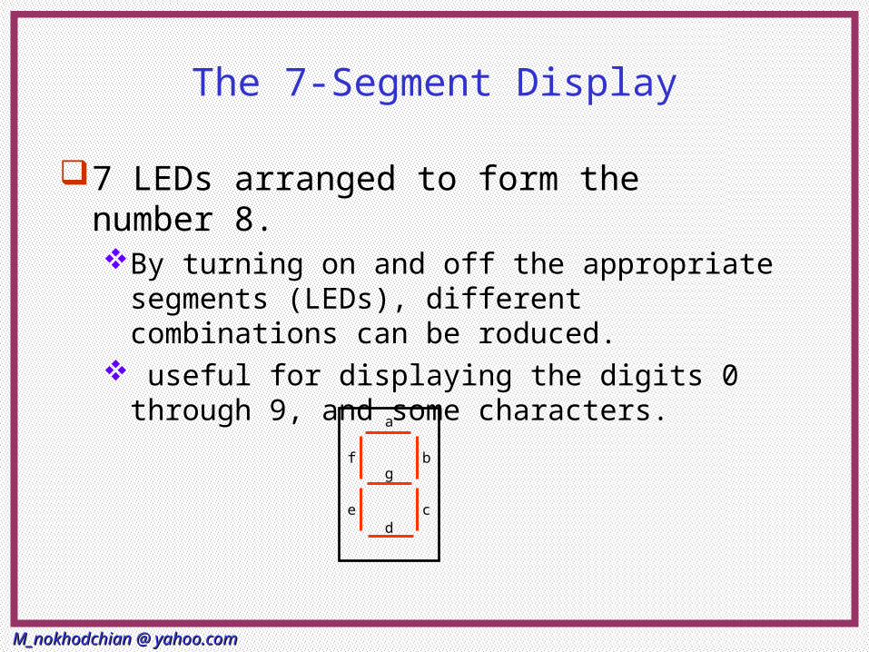
The 7-Segment Display
7 LEDs arranged to form the number 8.By turning on and off the appropriate
segments (LEDs), different combinations can be roduced.
useful for displaying the digits 0 through 9, and some characters.
a
b
c
f
e
g
d

M_nokhodchian @ yahoo.comM_nokhodchian @ yahoo.com MicroprocessorsMicroprocessors 1-1-2222
The 7-segment Display (Cont.) 7-segment displays come in 2 configurations:
Common Anode Common Cathode
As we have seen, it would be preferable to connect the cathode of each diode to the output pin.
Therefore, the common anode variety would be better for our interfacing needs.

M_nokhodchian @ yahoo.comM_nokhodchian @ yahoo.com MicroprocessorsMicroprocessors 1-1-2323
Interfacing a 7-segment display
Also, as seen with interfacing the LED, a resistor will be needed to control the current flowing through the diode. This leaves two possibilities:
Case 2 would be more appropriate as case 1 will produce different brightness depending on the number of LEDs turned on.

M_nokhodchian @ yahoo.comM_nokhodchian @ yahoo.com MicroprocessorsMicroprocessors 1-1-2424
Use of current buffer Interfacing to a DIP switch and 7-segment
display Output a ‘1’ to ON a segment We can use 74244 to common cathode 7_seg

M_nokhodchian @ yahoo.comM_nokhodchian @ yahoo.com MicroprocessorsMicroprocessors 1-1-2525
BCD to 7_Seg lookup table
mov a,p3
anl a,0fh
get_code:mov DPTR, #7s_tab
movc A, @A+DPRT
mov p1,a
7s_tab: db 3fh,30h,5bh,4fh,66h
db 6dh,7dh,07h,7fh,6fh
END
a
b
c
f
ed
f
e
a
b
e
g
d
a
b
c
g
d
b
c
fg
a
c
fg
d
a
c
f
e
g
d
a
b
c
a
b
c
f
e
g
d
a
b
c
fg
d
BCD p g f e d c b a7_seg
hex
0000 0 0 1 1 1 1 1 1 3f
0001 0 0 1 1 0 0 0 0 30
0010 0 1 0 1 1 0 1 1 5b
0011 0 1 0 0 1 1 1 1 4f
0100 0 1 1 0 0 1 1 0 66
0101 0 1 1 0 1 1 0 1 6d
0110 0 1 1 1 1 1 0 1 7d
0111 0 0 0 0 0 1 1 1 07
1000 0 1 1 1 1 1 1 1 7f
1001 0 1 1 0 1 1 1 1 6f