model 1030a indicator-totalizer installation, operation ... · model 1030a indicator-totalizer 2...
TRANSCRIPT
Model 1030A Indicator-Totalizer
Model 1030AIndicator-Totalizer
Installation, Operationand Maintenance Manual
M517Rev. B
TM
TOTALTOTALSET PT. RATE
LORATE
HIRATE
DISPLAY
Model 1030A Indicator-Totalizer
Table of Contents
General .......................................................................................................... 1
Specifications .................................................................................................. 1
Installation ....................................................................................................... 3
Dimensions ..................................................................................................... 4
Operation ........................................................................................................ 8
Programming ................................................................................................. 11
Programming Menu Descriptions .................................................................. 12
Programming Chart ....................................................................................... 16
Model 1030A Indicator-Totalizer
Installation, Operation & Maintenance
GENERAL
The Model 1030A is a microprocessor based indicator-totalizer. It gives you theability to display important process parameters such as rate, total, and setpoints. It contains a 20-point linearization table to allow flexibility in displayingrate and total from a non-linear meter. It also supplies outputs for driving lights,alarms, chart recorders, and totalization for remote operations.
A special mode gives you the capability of simultaneously viewing two flowparameters such as rate and total. The 1030A also contains a set point lockout system to prevent unauthorized changes from the front panel.
The 1030A may be completely factory programmed for your application. It iseasy to operate and to program when changes are required. Programmingis accomplished through an easy-to-use menu system. There are built-inscrolling help messages that explain each program step. A 10-year memorybacks up all program settings and parameters in case of a power failure.
SPECIFICATIONS
Flow Input A:Type: 4-20 mA current loopImpedance: 100 ohmVoltage: 5 VDCResponse: 3 HzResolution: 11 bitsAccuracy: ±0.1% at 25°C
±0.25% over temperature range
Flow Input B: Flow input inhibit (flow input ignored when pulled low)Require npn current sinking device.Internal 5.8K ohm pull-up resistor to 5 VDC
Voltage low: 0.0-1.3 VDCVoltage high: 2.8-24 VDC
Front panel control: pushbutton control (may be locked out)
Reset*:Rate meter: unlatch rate hi/lo set point outputs, or none;Totalizer: reset totalizer count, unlatch totalizer set point output, resettotalizer count and unlatch totalizer set point output, or noneNote*: When more than one function is available, the function that isitalicized is the program default. It is possible to change the functionthrough the program menu.
Control inputs: Contact closure or npn transistor pull down to groundimpedance: 5.8K ohm pull-up resistor to 5 VDClow: 0-1.0 VDC; high: 3.5-24 VDCresponse: min. low 30 millisec.; min. high 30 millisec.
Control Inputs 1 - 5: Reset totalizer count, unlatch totalizer set pointoutput, reset totalizer and unlatch totalizer set point, unlatch rate hi/loset points, or none. 1
Model 1030A Indicator-Totalizer
2
Power supply: 120/240 VAC +10%, –15%, 50/60 Hz, 0.2/0.1 amps; or18 - 27 VDC, 0.4 amps maximum, 6 watts maximum
Power output: 24 VDC ±5% at 100 mA max. for sensors and peripheralswhen unit is supplied with AC power input only
Rate meterRate multiplier: 0.0001 to 999999Accuracy: ±0.05%Rate smoothing: designate 0.5 to 7.5 second dynamic averaging in
0.5 second incrementsRate update: 0.5 seconds
Current output: 4-20 mA; 100 ohm impedance; optically isolatedLoad: 1000 ohms max. at 24 VDCCompliance voltage: 12-27 VDCResponse time: 0.5 seconds (follows rate meter)Accuracy: ±0.1% at 25°C; ±0.25% over temp. rangeResolution: 0.05% (11 bits)
Control outputs: npn trans. (150 mA max., 30 VDC max.)Control output 1: scaled totalizer pulse output with designated
pulse widthhigh speed: 1500 Hz. max.; 125 microsecond pulse widthmed. speed: 200 Hz. max.; 2 millisecond pulse widthlow speed: 10 Hz. max.; 50 millisecond pulse width
Control output 2: totalizer set point outputControl output 3: low rate set point outputControl output 4: high rate set point output
Note: Rate hi/lo set point output operations may either: follow theflow, be latched, or be timed from 0.1 to 999.9 seconds. The totalizerset point output operation may be either: latched, or timed from 0.1 to999.9 seconds.
CommunicationsType: RS-485 multidropBaud: 300, 600, 1200, 2400, 4800, 9600,19200Parity: space, even, or oddProtocol: Opto-22 compatible
Wiring terminals: 14 awg max., detachable
EnvironmentalOperating temperature: 32 to 131°F (0 to 55°C)Storage temperature: –40 to 158°F (–40 to 70°C)Humidity: 0 to 85% RH noncondensingPanel mount version: key pad is NEMA 4X with gasket that will seal
panel NEMA 4Wall mount version: enclosure and front panel are NEMA 4X
Model 1030A Indicator-Totalizer
INSTALLATION
Panel mounts: See dimensions for panel cut-out. Completely install the unitinto the panel.
Wall mounts: Mount unit to wall. Wires should be 18 inches long inside theenclosure from the point of entry to the point of termination. This will provideample length so the hinged door will swing freely and allow access to theterminals.
After installing unit, place the three adhesive cable clamps (enclosed) on thebottom rear of the unit near the wiring terminals as needed. Loop the threecable ties through the clamps and around the wires to transfer the strain fromthe terminal blocks to the clamps.
Wiring Notes
The following points should be kept in mind when wiring the unit:
• All connections should be made to the instrument with the power off.
• Improper wiring may cause damage to the instrument. Double check allconnections before powering.
• Do not exceed the power ratings of the components. Observe the maximumcurrent and voltage ratings as applicable. See Specifications section.
• An in-line fuse should be installed in the input power supply line. See theApplications Wiring section.
• Sensor, control, and AC power lines should not be routed in the sameconduit.
• AC power inputL1, L2 Terminals L1 and L2 are used for connecting the 115V or 230 VAC
power input. L1 uses the two left terminals. L2 uses the next twoterminals to the right.
115 VAC connectionTo connect 115 VAC power, join the fused hot lead to both of theL1 terminals and the neutral lead to both of the L2 terminals.
230 VAC connectionTo connect 230 VAC power, the left-most L1 terminal and the right-most L2 terminal should be connected to the two incoming powerlines while a wire jumper connects the right-most L1 terminal andthe left-most L2 terminal. One of the incoming leads should be fused.
/ / / This chassis ground terminal should be connected to earth ground.This connection is optional only if the unit is powered by 24 VDC, andthe relays are not used to switch AC power.
• When connecting inductive loads to the control outputs, diode protectionshould be provided.
• On power-up, if the display reads “Run Installation,” press the “Reset” keyto clear. This is an indication that the unit has not been programmed. Toprogram the unit, see page 11.
3
Model 1030A Indicator-Totalizer
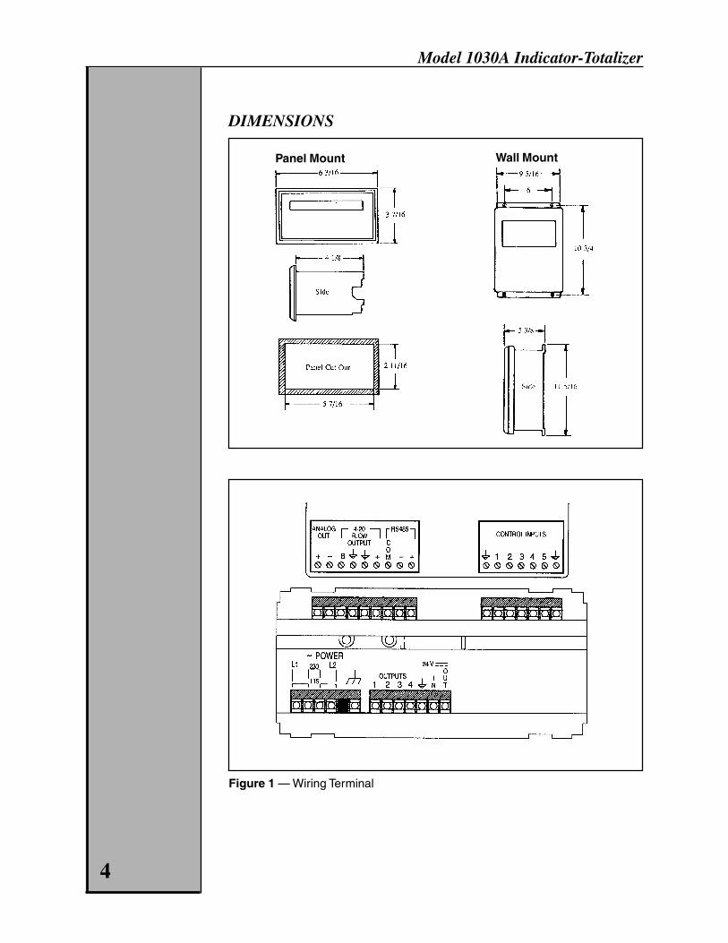
Figure 1 — Wiring Terminal
4
Panel Mount Wall Mount
DIMENSIONS
Model 1030A Indicator-Totalizer
5
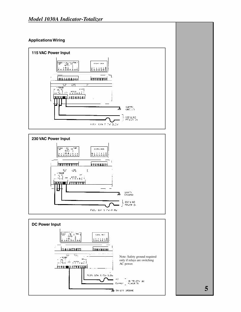
Applications Wiring
115 VAC Power Input
230 VAC Power Input
DC Power Input
Note: Safety ground requiredonly if relays are switchingAC power.
Model 1030A Indicator-Totalizer
6
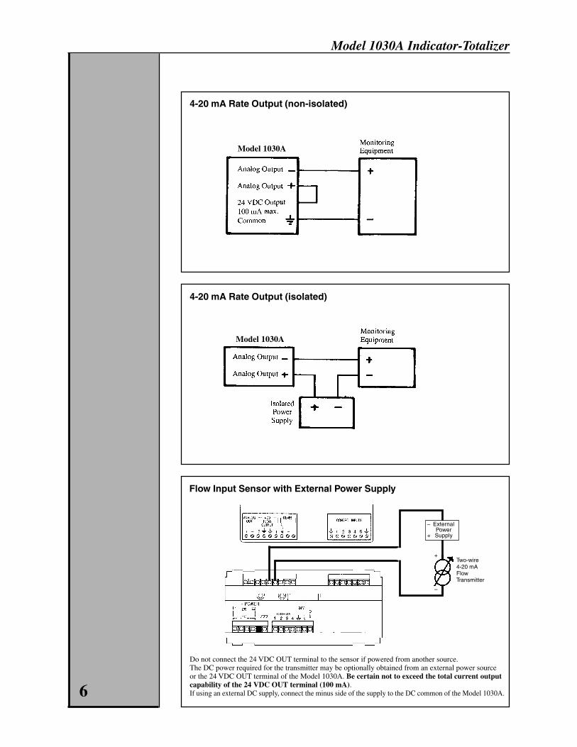
4-20 mA Rate Output (non-isolated)
4-20 mA Rate Output (isolated)
Flow Input Sensor with External Power Supply
Do not connect the 24 VDC OUT terminal to the sensor if powered from another source.The DC power required for the transmitter may be optionally obtained from an external power sourceor the 24 VDC OUT terminal of the Model 1030A. Be certain not to exceed the total current outputcapability of the 24 VDC OUT terminal (100 mA).If using an external DC supply, connect the minus side of the supply to the DC common of the Model 1030A.
Model 1030A
Model 1030A
Two-wire4-20 mAFlowTransmitter
ExternalPowerSupply
–
+
+
–
Model 1030A Indicator-Totalizer
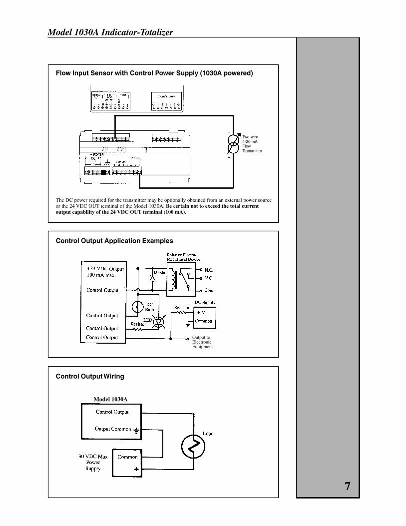
Control Output Application Examples
Flow Input Sensor with Control Power Supply (1030A powered)
The DC power required for the transmitter may be optionally obtained from an external power sourceor the 24 VDC OUT terminal of the Model 1030A. Be certain not to exceed the total currentoutput capability of the 24 VDC OUT terminal (100 mA).
Control Output Wiring
7
Model 1030A
Two-wire4-20 mAFlowTransmitter
Output toElectronicEquipment
+ 3
Model 1030A Indicator-Totalizer
OPERATION
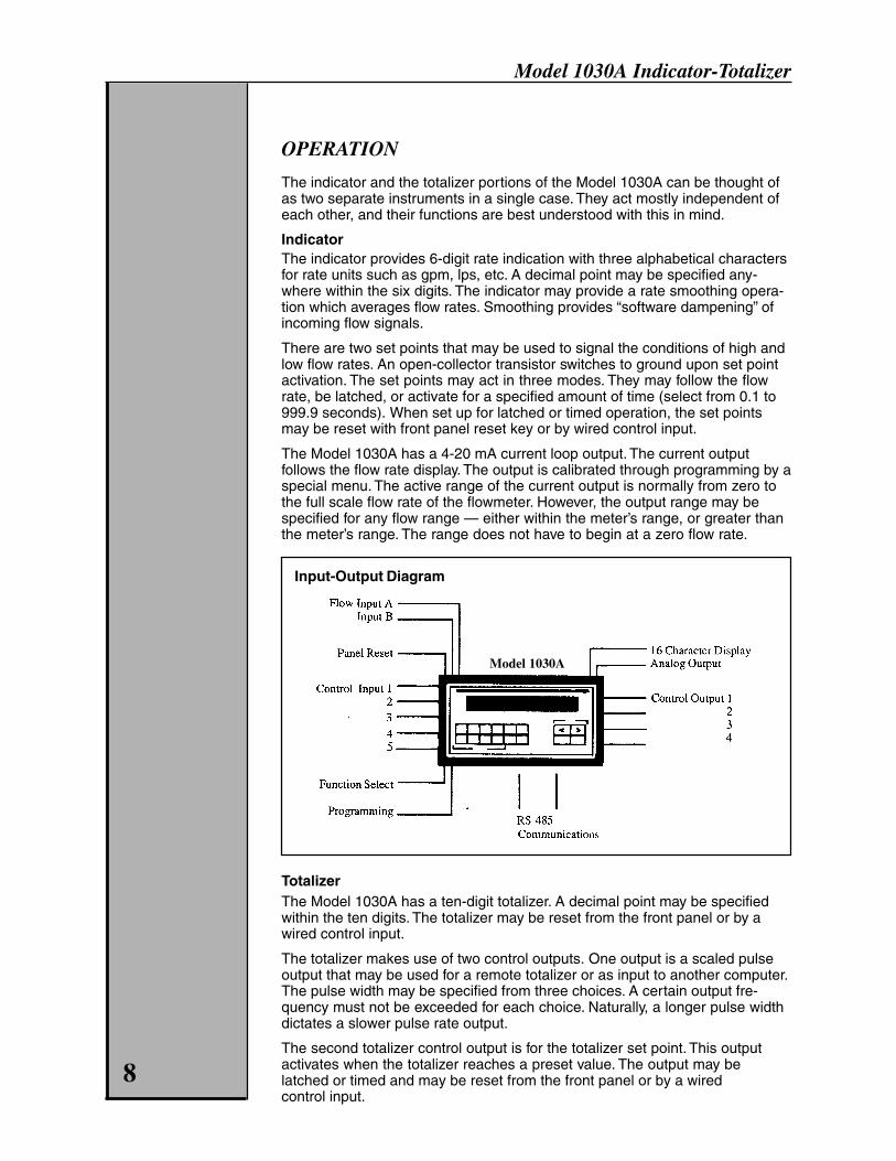
The indicator and the totalizer portions of the Model 1030A can be thought ofas two separate instruments in a single case. They act mostly independent ofeach other, and their functions are best understood with this in mind.
IndicatorThe indicator provides 6-digit rate indication with three alphabetical charactersfor rate units such as gpm, lps, etc. A decimal point may be specified any-where within the six digits. The indicator may provide a rate smoothing opera-tion which averages flow rates. Smoothing provides “software dampening” ofincoming flow signals.
There are two set points that may be used to signal the conditions of high andlow flow rates. An open-collector transistor switches to ground upon set pointactivation. The set points may act in three modes. They may follow the flowrate, be latched, or activate for a specified amount of time (select from 0.1 to999.9 seconds). When set up for latched or timed operation, the set pointsmay be reset with front panel reset key or by wired control input.
The Model 1030A has a 4-20 mA current loop output. The current outputfollows the flow rate display. The output is calibrated through programming by aspecial menu. The active range of the current output is normally from zero tothe full scale flow rate of the flowmeter. However, the output range may bespecified for any flow range — either within the meter’s range, or greater thanthe meter’s range. The range does not have to begin at a zero flow rate.
Input-Output Diagram
TotalizerThe Model 1030A has a ten-digit totalizer. A decimal point may be specifiedwithin the ten digits. The totalizer may be reset from the front panel or by awired control input.
The totalizer makes use of two control outputs. One output is a scaled pulseoutput that may be used for a remote totalizer or as input to another computer.The pulse width may be specified from three choices. A certain output fre-quency must not be exceeded for each choice. Naturally, a longer pulse widthdictates a slower pulse rate output.
The second totalizer control output is for the totalizer set point. This outputactivates when the totalizer reaches a preset value. The output may belatched or timed and may be reset from the front panel or by a wiredcontrol input.
8
Model 1030A
Model 1030A Indicator-Totalizer
9
Front Panel Value Display
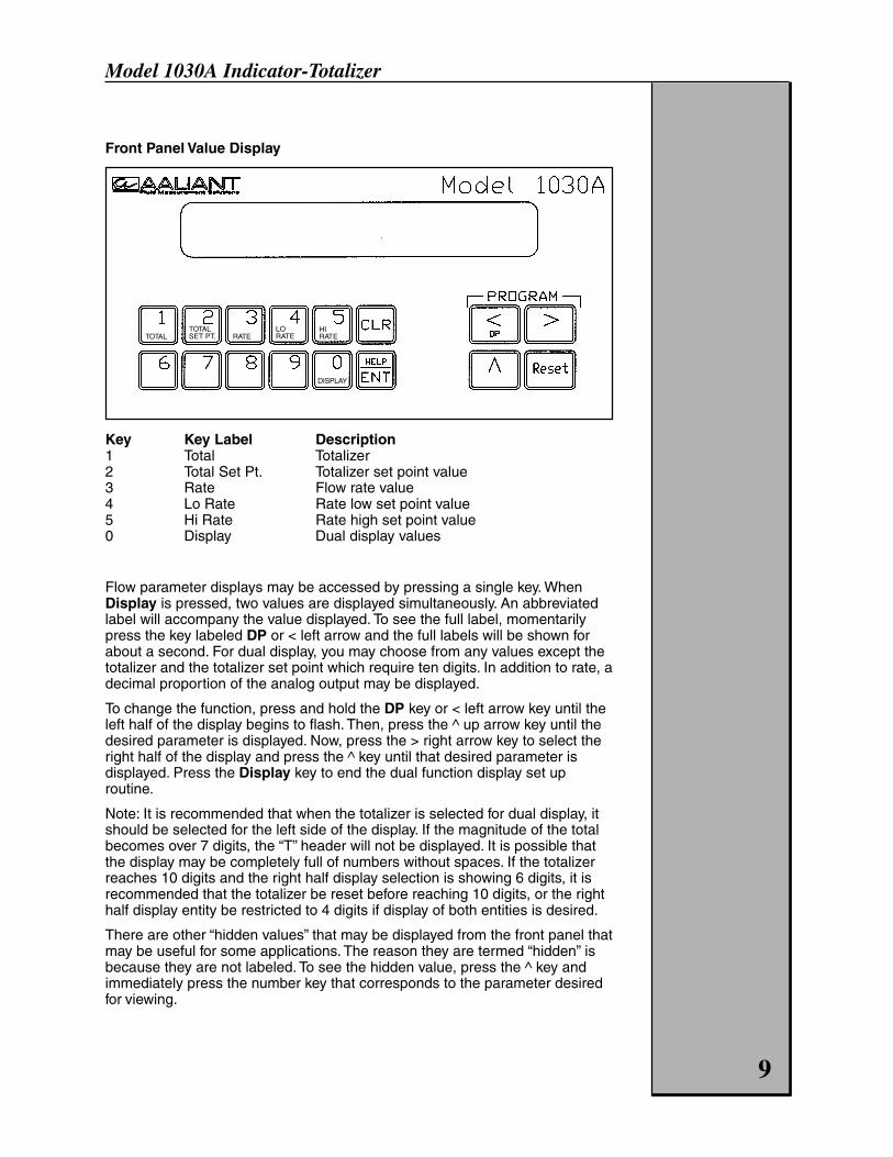
Key Key Label Description1 Total Totalizer2 Total Set Pt. Totalizer set point value3 Rate Flow rate value4 Lo Rate Rate low set point value5 Hi Rate Rate high set point value0 Display Dual display values
Flow parameter displays may be accessed by pressing a single key. WhenDisplay is pressed, two values are displayed simultaneously. An abbreviatedlabel will accompany the value displayed. To see the full label, momentarilypress the key labeled DP or < left arrow and the full labels will be shown forabout a second. For dual display, you may choose from any values except thetotalizer and the totalizer set point which require ten digits. In addition to rate, adecimal proportion of the analog output may be displayed.
To change the function, press and hold the DP key or < left arrow key until theleft half of the display begins to flash. Then, press the ^ up arrow key until thedesired parameter is displayed. Now, press the > right arrow key to select theright half of the display and press the ^ key until that desired parameter isdisplayed. Press the Display key to end the dual function display set uproutine.
Note: It is recommended that when the totalizer is selected for dual display, itshould be selected for the left side of the display. If the magnitude of the totalbecomes over 7 digits, the “T” header will not be displayed. It is possible thatthe display may be completely full of numbers without spaces. If the totalizerreaches 10 digits and the right half display selection is showing 6 digits, it isrecommended that the totalizer be reset before reaching 10 digits, or the righthalf display entity be restricted to 4 digits if display of both entities is desired.
There are other “hidden values” that may be displayed from the front panel thatmay be useful for some applications. The reason they are termed “hidden” isbecause they are not labeled. To see the hidden value, press the ^ key andimmediately press the number key that corresponds to the parameter desiredfor viewing.
TOTALTOTALSET PT. RATE
LORATE
HIRATE
DISPLAY
Model 1030A Indicator-Totalizer
Changing Set Point ValuesRate and totalizer set point may be easily changed from the front panel. First,press the function key desired as if to view the set point.
To change the value, press the CLR key, enter the new value using the num-ber keys, then press ENT. If you change your mind before pressing the ENTkey, just press the CLR key and the original value will be retained.
It is possible to selectively “lock out” the set point values so they cannot bechanged from the front panel. This is done from within the program mode. Seethe Programming section.
Front Panel Control – Reset KeyThe Reset key may be used to unlatch the rate or totalizer set point outputs, orto reset the totalizer count. Any combination of these functions may be chosenfrom within the program mode. Standard factory setting is “None.”
Flow InputsThere are two terminals for flow inputs (plus associated ground terminals):Input A accepts a 4-20 mA analog signal from the flow meter or flowtransmitter.Input B is a flow inhibit input. When Input B is connected to ground, the Model1030A will ignore any incoming pulses on Input A. When Input B is not used orconnected to a logical positive voltage (see Specifications), Input A is activeas normal.
Wired Control InputsThere are five wired control inputs that perform single or multiple functionssimilar to the Reset key. When switched to ground, the specific function isperformed. Each control input has a specific function or functions which cannotbe altered.
Input # Function1 - 5 Reset totalizer count, unlatch totalizer set point output, reset
totalizer and unlatch totalizer set point, unlatch rate hi/lo set points,or none.
Control OutputsFour control outputs are available. These are npn transistors that will switch aload to ground when activated. They may be used for electro-mechanicaldevices such as counters or relays, turning on lamps, or used to signal anautomated processing device. The maximum current sinking capability is 150milliamps and the maximum DC voltage is 30 volts.
Output # Function1 Scaled totalizer pulse output2 Totalizer set point output3 Rate low set point output4 Rate high set point output
The totalizer set point output may be specified from within the program modeto have latched or timed (from 0.1 too 999.9 seconds) operation.
The rate set points have three modes of operation. One mode is for the setpoints to follow the flow rate. That is, the outputs activate and deactivate as theflow rate passes above and below the set values. The two rate set points mayact independently by being latched or timed from 0.1 to 999.9 seconds.
10

Model 1030A Indicator-Totalizer
In either case, latched or timed, an output that has been activated will remainactivated as long as the responsible condition exists. When the conditionceases to exist, the output may either time out or be unlatched by a controlinput.
RS-485 CommunicationsThe Model 1030A has an RS-485 communications link for two-way communi-cation with other computers. This link may be used to make programmingchanges, set point changes, query flow data, and perform control functions.The Model 1030A may occupy a communication line with up to 100 units —each having a unique identification number (0 to 255). A single two-wire linemay be up to 4000 feet long without the use of signal repeaters. The communi-cations link is specified as RS-485 multi-drop. Baud rates of 300, 600, 1200,2400, 4800, 9600, and 19200 are possible. Parity may be specified as space,even, or odd. The protocol is Opto-22 compatible. For communication com-mand specifics, please contact your Aaliant representative.
PROGRAMMING
See Programming Chart.
Programming the Model 1030A may be done from the front panel by twomethods. The preferred method is using the menu that may be steppedthrough for making changes. The second method makes use of a rapid accesstechnique that may be quicker for a simple change but requires the program-ming diagram to be in hand.
Enter the Programming ModeSimultaneously press the < left arrow and the > right arrow keys. Notice thatthese keys have “Program” labeled immediately above them. A password maybe requested if an operator has specified a password during a previousprogramming session. The Model 1030A comes from the factory with nopassword set. Setting of the password is explained on page 15. Enter thecorrect password and press the ENT key. If an incorrect password is enteredthe message “PW ERROR” will be flashed and the unit will again ask for apassword. The user may try again if he desires. He may leave the passwordentry mode and return to the run mode by simultaneously pressing the < and >keys. If the password display is left idle, the unit will return to run mode auto-matically after 15 seconds.
Once the program mode is entered, “PROGRAM ?” will be displayed.
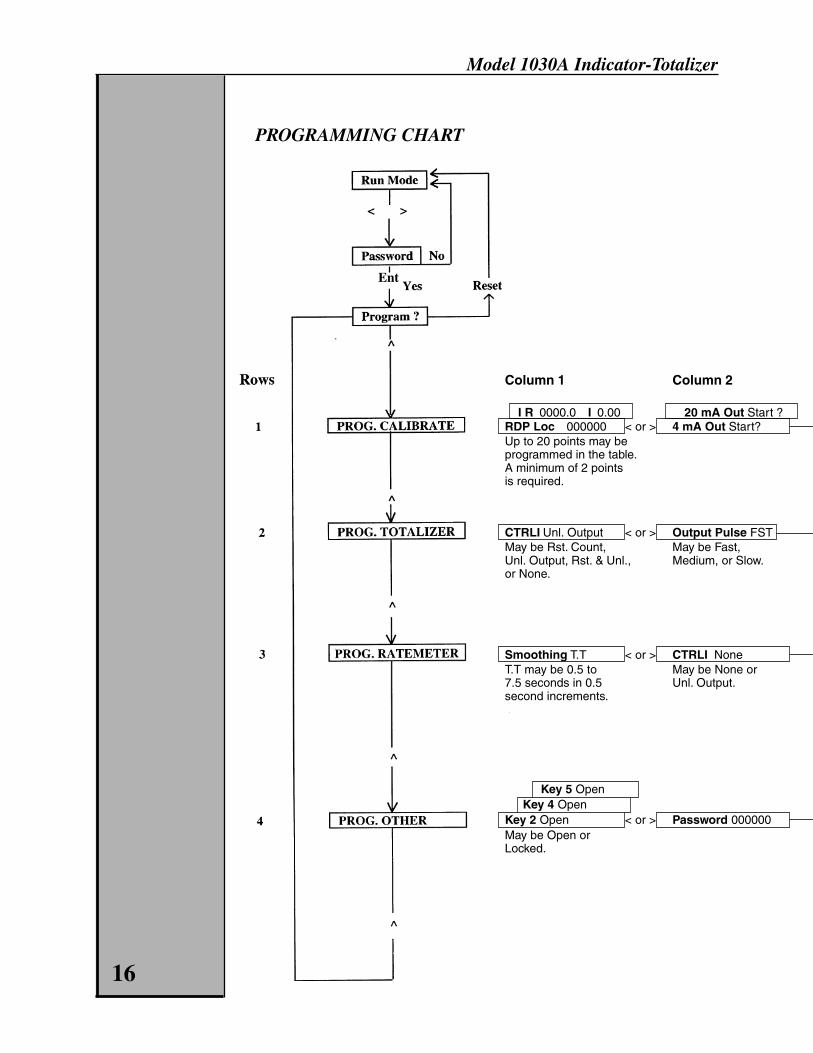
Rapid Access Programming MethodProgram cells may be accessed directly from the “PROGRAM ?” screen byentering the row number and the column number from the Programming Charton page 16. Other cells may be accessed by pressing < and > to get the“PROGRAM ?” display and entering another row and column number.
Sequential Menu Programming MethodOnce the “PROGRAM ?” display is obtained, main menu items may be se-lected by pressing the ^ up arrow key. These menu items all contain the word“PROG.” See Programming Chart on page 16. Once the main menu selectionhas been made, the > and < keys may be used to move to submenu items andto move back to the main menu. Then use the ^ key to select another mainmenu item. 11
Model 1030A Indicator-Totalizer
Help MessagesWhen positioned at any submenu item, the Help key may be pressed, and ahelpful programming message will scroll across the display. After the messagehas completed, the display will return to the submenu item. If you do not wantto read the entire message, pressing any key will end the message.
Returning to Run ModeThe operator may return to the running mode by simultaneously pressing the <and > keys to obtain the “PROGRAM ?” display. Then, press the Reset key toexit the programming mode.
PROGRAM MENU DESCRIPTIONS
See Programming Chart, page 16.
PROG. CALIBRATIONRate Decimal PointThe decimal point position of the rate meter may be selected using this display.
Example: Use the 0, 1, 2, 3, or 4 keys to select the location for the decimalpoint.
Linearization TableThis display is used when entering the calibration settings for different flowrates and 4-20 mA current inputs. For a linear meter, points 1 and 2 must beselected, and data must be entered for the low and high flow rates and associ-ated current inputs. For a non-linear meter, up to 20 points may be entered toassign different flow rates to the applicable 4-20 mA current inputs.
4 mA Out StartThis display is used when calibrating the analog output of the unit.
Operation: To calibrate the analog output, connect the analog output “+”terminal to +24 VDC out. Connect the analog output “–” terminal to groundthrough a current meter. Press the CLR key. Use the < and > keys to adjust theoutput current to 4 mA and then press the ENT key. Use the ^ key to select the20 mA level and repeat the process.
4 mA RateThis display is used to select the active range of the analog output. Enter theflow rate that is supposed to be represented by 4 milliamps, normally zero (0).Press the ^ key and enter the flow rate that is to be represented by 20milliamps, normally the rated full scale flow rate of the meter.
Operation: Use the ^ key to select the 4 or 20 mA rate. Use the 0-9 and ENTkeys to enter a new rate.
FLO 4 mA In End ?This step is used to calibrate the flow input.Help message: To calibrate the flow analog input using a current source, setthe input current to exactly 4 mA and press the RESET key. The display willblack momentarily to indicate that calibration for that level is completed.Use the ^ key to select the 20 mA and repeat the process.
12
Model 1030A Indicator-Totalizer
PROG. TOTALIZERControl InputsAssign control inputs 1-5 to a totalizer function. Choices are none, reset count,unlatch outputs, or reset count and unlatch outputs.
Operation: Use keys 1-5 to select the control input and use the ^ key to assigna specific totalizer function.
Output PulseFast 125 microsecond pulse width, output 1500 pulses/second max.Medium 2 millisecond pulse width, output 200 pulses/second max.Slow 50 millisecond pulse width, 10 pulses/seconds max. frequency
Operation: Use the ^ key to select the function of the totalizer output.
Output Set PointDecide the totalizer set point output. If 0.0 is entered, the output will belatched. If 0.1 to 999.9 is entered, the output will be timed. The output willremain on, if timed, for as long as the totalizer condition exists and for thetimeout period. The timeout period may be preempted by unlatching theoutput.
Operation: Use the CLR key to enable entry of a new timeout. Use the 0-9and ENT keys to enter the timeout value of the output.
ResetThe front panel reset key can be configured to perform multiple or no functionsfor the totalizer. These functions include reset totalizer count, unlatch totalizerset point output, reset totalizer count and unlatch totalizer set point output,and none.
Operation: Use the ^ key to select the totalizer function of the Reset key.
Totalizer Decimal PointThe decimal point position of the totalizer may be selected using this display.0, 1, or 2 totalizer decimal points may be selected.
Example: Use the ^ key to select the decimal point location for the totalizer.
PROG. RATEMETERSmoothingA built-in dynamic averager performs software dampening. With this, a stablereading of flow rate may be obtained from a pulsating flow system. A smooth-ing factor of 0.5 to 7.5 may be set in 0.5 increments. By setting the smoothingfactor at 0.5, no damping is performed. A smoothing factor of 7.5 provides a7.5 second time delay for 100% display settling after a change in flow rate.Instantaneous rate readings are taken and averaged to produce a singlereading to be displayed. With each rate update, the oldest reading will beincorporated into the average.
Operation: Use the ^ key to select a new rate smoothing time.
13
Model 1030A Indicator-Totalizer
Control InputsAssign control inputs 1-5 to a ratemeter function. Choices are unlatch the ratehi/lo set point outputs or none.
Operation: Use keys 1-5 to select the control input and use the ^ key to assigna specific ratemeter function.
Outputs FollowThe high and low flow rate set points may operate three different ways. Theymay follow the flow rate, be latched, or be timed. If latched, set the timeoutperiod for 0.0 seconds. If timed, set the timeout from 0.1 to 999.9 seconds. Theoutput will persist until after the responsible conditions cease and the timeoutperiod has expired or until the output is unlatched.
Operation: Use the ^ key to select whether the rate outputs follow the rateor are timed. If timed, use the < and > keys to select either the lo or hi rateoutput. Use the CLR key to enable a new entry. Use the 0-9 and ENT keysto enter a new output time. The output is latched if a time of 0.0 is entered.
ResetThe front panel reset key can perform either an unlatching of the rate set pointoutputs or no function at all.
Operation: Use the ^ key to select the rate meter function of the Reset key.
Rate at ZeroIn absence of the flow pulse input, the rate at zero is the period that the ratemeter will show the last legitimate flow reading before showing a zero flowrate. The period may be set from 1 to 15 seconds.
Operation: Use the CLR key to enable a new entry. Use the 0-9 keys and ENTto enter a new rate zero time.
Rate HeaderThree alphabetical characters and a blank character may be used to label theflow rate display with engineering units. The last character will be M, H, or S forminutes, hours, or seconds.
Operation: Use the > and< keys to select which location to program. Use the ^key to select the character for that location.
PROG. OTHERKey 2 Open (Also, keys 4 and 5)The totalizer set point value, rate low set point value, and the rate high setpoint value may be designated as open or locked. Locking the value preventsthe changing of the set point value from the front panel unless it is firstreopened in the programming mode. This protects against unauthorizedpersons having access to change the set points in critical control applications.
Operation: Use the 2, 4, or 5 keys to select which set point mode to program.Use the ^ key to select whether or not the selected set point is locked.
14
Model 1030A Indicator-Totalizer
PasswordA password may be specified for the next entry into the programming mode. Apassword of zeros (000000) means that no password is required for programmode entry. Do not forget your password!
Operation: Use the CLR key to enable a new entry. Use the 0-9 and ENT keysto enter a new password.
Baud - - - ParityThe baud rate and parity must be specified when using the RS-485 communi-cations link. The baud rate should be chosen from 300, 600, 1200, 2400, 4800,9600, 19200. The parity may be space (none), even, or odd.
Operation: Use the CLR key to enable entry. Use the 0-9 and ENT keys toenter the communication baud rate. Use the ^ key to select odd, even, orspace parity.
ID - - - TimeThe Model 1030A’s identification number must be set whenever using theRS-485 communication link. This must be a number between 0 and 255. Notwo units on the same link may have the same ID. Also, the minimum commu-nication response time for the unit must be specified. It may be selected from0, 10, 100, or 500 milliseconds. A longer time is normally given for non-time-critical applications.
Operation: Use the CLR key to enable entry. Use the 0-9 and ENT keys toenter the unit identity number from 0 to 255. Each unit on the communicationlink must have a unique number. Use the ^ key to select the minimumcommunication response time.
DiagnosticsTwo items may be tested when the diagnostics are run — the display and thecomputer itself. You may check for missing character segments in the displayby pressing the ^ key. All “8”s and decimal points should be displayed. Pressthe ^ key again and all “*”s will be displayed. Again, you should check formissing segments. Pressing the ^ key again will start the computer’sself-diagnostics test. Any errors will be flashed on the display.
Operation: Press the ^ key three times to cycle through the diagnostic tests.
15
Model 1030A Indicator-Totalizer
PROGRAMMING CHART
Column 1 Column 2
I R 0000.0 I 0.00 20 mA Out Start ?RDP Loc 000000 < or > 4 mA Out Start?Up to 20 points may beprogrammed in the table.A minimum of 2 pointsis required.
CTRLI Unl. Output < or > Output Pulse FSTMay be Rst. Count, May be Fast,Unl. Output, Rst. & Unl., Medium, or Slow.or None.
Smoothing T.T < or > CTRLI NoneT.T may be 0.5 to May be None or7.5 seconds in 0.5 Unl. Output.second increments.
Key 5 OpenKey 4 Open
Key 2 Open < or > Password 000000May be Open orLocked.
16
Ent
Model 1030A Indicator-Totalizer
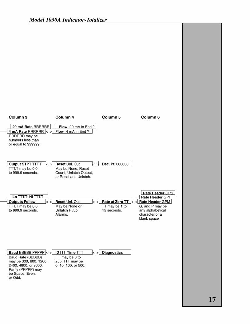
Column 3 Column 4 Column 5 Column 6
20 mA Rate RRRRRR Flow 20 mA in End ?4 mA Rate RRRRRR < > Flow 4 mA in End ?RRRRRR may benumbers less thanor equal to 999999.
Output STPT TTT.T < > Reset Unl. Out < > Dec. Pt. 000000TTT.T may be 0.0 May be None, Resetto 999.9 seconds. Count, Unlatch Output,
or Reset and Unlatch.
Rate Header GPSLo TTT.T Hi TTT.T Rate Header GPH
Outputs Follow < > Reset Unl. Out < > Rate at Zero TT < > Rate Header GPMTTT.T may be 0.0 May be None or TT may be 1 to G, and P may beto 999.9 seconds. Unlatch Hi/Lo 15 seconds. any alphabetical
Alarms. character or ablank space
Baud BBBBB PPPPP < > ID I I I Time TTT < > DiagnosticsBaud Rate (BBBBB) I I I may be 0 tomay be 300, 600, 1200, 255. TTT may be2400, 4800, or 9600. 0, 10, 100, or 500.Parity (PPPPP) maybe Space, Even,or Odd.
17

Model 1030A Indicator-Totalizer
150 Venture BoulevardSpartanburg, SC 29306
Phone: (800) 778-9251, (864) 574-3327Fax: (864) 574-8063Repair Service: (800) 778-9249Internet: www.aaliant.comE-mail: [email protected]
M517 Rev. B 1/01A
Product Line
™