model 1030f indicator-totalizer installation, operation ...model 1030f indicator-totalizer...
TRANSCRIPT

Model 1030F Indicator-Totalizer
Model 1030FIndicator-Totalizer
Installation, Operationand Maintenance Manual
M518 Rev. B

Model 1030F Indicator-Totalizer
Table of Contents
General .......................................................................................................... 1
Installation ....................................................................................................... 1
Operation ........................................................................................................ 7
Programming .................................................................................................. 11
Programming Menu Descriptions .................................................................. 12
Programming Chart ....................................................................................... 14
Specifications ................................................................................................ 18
Dimensions ................................................................................................... 20

Model 1030F Indicator-Totalizer
Installation, Operation & Maintenance
GENERAL
The Model 1030F is a microprocessor based indicator-totalizer. It gives you theability to display important process parameters such as rate, total, and setpoints. It also supplies outputs for driving lights, alarms, chart recorders, andtotalization for remote operations.
A special mode gives you the capability of simultaneously viewing two flowparameters such as rate and total. The 1030F also contains a set point lockout system to prevent unauthorized changes from the front panel.
The 1030F may be completely factory programmed for your application. It iseasy to operate and to program when changes are required. Programmingis accomplished through an easy-to-use menu system. There are built-inscrolling help messages that explain each program step. A 10-year memorybacks up all program settings and parameters in case of a power failure.
INSTALLATIONPanel mounts: See dimensions for panel cut-out. Completely install the unitinto the panel.
Wall mounts: Mount unit to wall. Wires should be 18 inches long inside theenclosure from the point of entry to the point of termination. This will provideample length so the hinged door will swing freely and allow access to theterminals.
After installing unit, place the three adhesive cable clamps (enclosed) on thebottom rear of the unit near the wiring terminals as needed. Loop the threecable ties through the clamps and around the wires to transfer the strain fromthe terminal blocks to the clamps.
Wiring NotesThe following points should be kept in mind when wiring the unit:
• All connections should be made to the instrument with the power off.
• Improper wiring may cause damage to the instrument. Double check allconnections before powering.
• Do not exceed the power ratings of the components. Observe the maximumcurrent and voltage ratings as applicable. See Specifications section.
• An in-line fuse should be installed in the input power supply line. See theApplications Wiring section.
• Sensor, control, and AC power lines should not be routed in the sameconduit.
• AC power inputL1,L2 Terminals L1 and L2 are used for connecting the 115V or 230 VAC
power input. L1 uses the two left terminals. L2 uses the next twoterminals to the right.
1

2
Wiring Control Inputs
Applications Wiring
Powering the Model 1030F – 115 VAC version
Powering the Model 1030F – 230 VAC version
All grounds (common) are connected internally.

3
Powering the Model 1030F with DC supply
Flow input or control input using switch contact closure
4-20 mA rate output (non-isolated)
4-20 mA rate output (isolated)

Model 1030F Indicator-Totalizer
4
Flow input or control input utilizing open-collector npntransistor
Flow input or control input using open-collector npn transistorwith pull-up resistor
Control output application examples

Model 1030F Indicator-Totalizer
5
Wiring Aaliant Transmitters to the Model 1030FModel 840 Model 1030F
black Input Abrown Input Commonwhite No connection
Model 860 Model 1030Fgreen Input Awhite Input Commonbrown +24 V output
Note: Place a 1200 to 1500 ohm resistor (3/4 watt or greater) in series with thewhite wire as R1. Place a 1500 ohm resistor between the green wire andground as R2. In some cases, it may be necessary to substitute a resistor forR2 in the range of 1200 to 2000 ohms. Input speed is 7500 Hz.
Control output wiring
Model 1050 Model 1030FV in 24 V outputP out Input AGround Input Common
R-11 or R-12 with Reed Switch,R-15, R-39 Model 1030F
white Input Ablack Input Common
Model 1030F Indicator-Totalizer
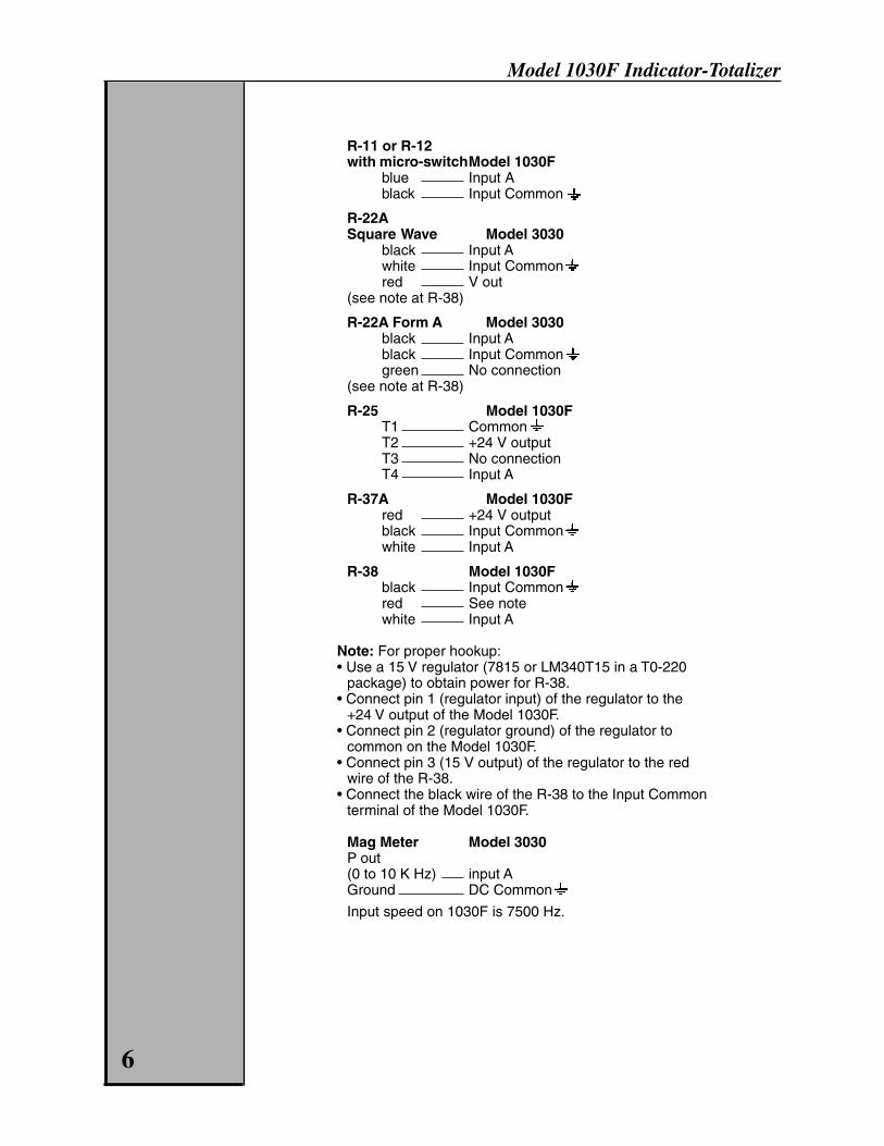
R-11 or R-12with micro-switchModel 1030F
blue Input Ablack Input Common
R-22ASquare Wave Model 3030
black Input Awhite Input Commonred V out
(see note at R-38)
R-22A Form A Model 3030black Input Ablack Input Commongreen No connection
(see note at R-38)
R-25 Model 1030FT1 CommonT2 +24 V outputT3 No connectionT4 Input A
R-37A Model 1030Fred +24 V outputblack Input Commonwhite Input A
R-38 Model 1030Fblack Input Commonred See notewhite Input A
Note: For proper hookup:• Use a 15 V regulator (7815 or LM340T15 in a T0-220
package) to obtain power for R-38.• Connect pin 1 (regulator input) of the regulator to the
+24 V output of the Model 1030F.• Connect pin 2 (regulator ground) of the regulator to
common on the Model 1030F.• Connect pin 3 (15 V output) of the regulator to the red
wire of the R-38.• Connect the black wire of the R-38 to the Input Common
terminal of the Model 1030F.
Mag Meter Model 3030P out(0 to 10 K Hz) input AGround DC Common
Input speed on 1030F is 7500 Hz.
6

Model 1030F Indicator-Totalizer
OPERATIONThe indicator and the totalizer portions of the Model 1030F can be thought ofas two separate instruments in a single case. They act mostly independent ofeach other, and their functions are best understood with this in mind.
IndicatorThe indicator provides 6-digit rate indication with three alphabetical charactersfor rate units such as gpm, lps, etc. A decimal point may be specified any-where within the six digits. The indicator may provide a rate smoothing opera-tion which averages pulsating flow rates. Smoothing provides “softwaredampening” of incoming flow signals.
There are two set points that may be used to signal the conditions of high andlow flow rates. An open-collector transistor switches to ground upon set pointactivation. The set points may act in three modes. They may follow the flowrate, be latched, or activate for a specified amount of time (select from 0.1 to999.9 seconds). When set up for latched or timed operation, the set pointsmay be reset with front panel reset key or by wired control input.
The Model 1030F has a 4-20 mA current loop output. The current outputfollows the flow rate display. The output is calibrated through programming by aspecial menu. The active range of the current output is normally from zero tothe full scale flow rate of the flow meter. However, the output range may bespecified for any flow range — either within the meter’s range, or greater thanthe meter’s range. The range does not have to begin at a zero flow rate.
Input-Output Diagram
TotalizerThe Model 1030F has a ten-digit totalizer. A decimal point may be specifiedwithin the ten digits. The totalizer may be reset from the front panel or by awired control input.
The totalizer makes use of two control outputs. One output is a scaled pulseoutput that may be used for a remote totalizer or as input to another computer.The pulse width may be specified from three choices. A certain output fre-quency must not be exceeded for each choice. Naturally, a longer pulse widthdictates a slower pulse rate output.
The second totalizer control output is for the totalizer set point. This outputactivates when the totalizer reaches a preset value. The output may belatched or timed and may be reset from the front panel or by a wiredcontrol input.
7

Model 1030F Indicator-Totalizer
Front Panel Value Display
Key Key Label Description1 Total Totalizer2 Total Set Pt. Totalizer set point value3 Rate Flow rate value4 Lo Rate Rate low set point value5 Hi Rate Rate high set point value0 Display Dual display values
Hidden valuesKeys Function Description^, then 1 K factor Pulses input per unit volume value^, then 2 Calculated kmf hi Portion greater than or equal to one^, then 3 Calculated kmf lo (Portion less than one) Kmf hi and kmf lo
values may be added to tell the operatorthe “unit volume per pulse input” or thereciprocal of the K factor.
^, then 4 R factor Rate multiplier^, then 5 Analog fraction Percentage between 4-20 milliamps
at which the analog output is operating^, then 0 Software version Lets the customer and Aaliant personnel
know the version of software used
Front Panel DisplayFlow parameter displays may be accessed by pressing a single key. WhenDisplay is pressed, two values are displayed simultaneously. An abbreviatedlabel will accompany the value displayed. To see the full label, momentarilypress the key labeled DP or < left arrow and the full labels will be shown forabout a second. For dual display, you may choose from any values except thetotalizer and the totalizer set point which require ten digits. In addition to rate,a decimal proportion of the analog output may be displayed.
To change the function, press and hold the DP key or < left arrow key until theleft half of the display begins to flash. Then, press the ^ up arrow key until thedesired parameter is displayed. Now, press the > right arrow key to select theright half of the display and press the ^ key until that desired parameter isdisplayed. Press the Display key to end the dual function display set uproutine.
Note: It is recommended that when the totalizer is selected for dual display, itshould be selected for the left side of the display. If the magnitude of the totalbecomes over 7 digits, the “T” header will not be displayed. It is possible thatthe display be completely full of numbers without spaces. If the totalizerreaches 10 digits and the right half display selection is showing 6 digits, it isrecommended that the totalizer be reset before reaching 10 digits, or the righthalf display entity be restricted to 4 digits if display of both entities is desired.
8
1TOTAL
2TOTALSET PT
3RATE
4LORATE
5HIRATE
0DISPLAY ENT
HELP6 7 8 9
CLR
Reset
< >
<
DP

Model 1030F Indicator-Totalizer
There are other “hidden values” that may be displayed from the front panelthat may be useful for some applications. The reason they are termed “hidden”is because they are not labeled. To see the hidden value, press the ^ key andimmediately press the number key that corresponds to the parameter desiredfor viewing. See table on page 8.
Changing Set Point ValuesRate and totalizer set point may be easily changed from the front panel. First,press the function key desired as if to view the set point.
To change the value, press the CLR key, enter the new value using thenumber keys, then press ENT. If you change your mind before pressing theENT key, just press the CLR key and the original value will be retained.
It is possible to selectively “lock out” the set point values so they cannot bechanged from the front panel. This is done from within the program mode. Seethe Programming section.
Front Panel Control – Reset KeyThe Reset key may be used to unlatch the rate or totalizer set point outputs,or to reset the totalizer count. Any combination of these functions may bechosen from within the program mode. Standard factory setting is “None.”
Flow InputsThere are two terminals for flow inputs (plus associated ground terminals):Input A accepts electrical pulses from the flow meter or flow transmitter.Input B is a flow inhibit input. When Input B is connected to ground, the Model1030F will ignore any incoming pulses on Input A. When Input B is not used orconnected to a logical positive voltage (see Specifications), Input A is activeas normal.
Wired Control InputsThere are five wired control inputs that perform single or multiple functionssimilar to the Reset key. When switched to ground, the specific function isperformed. Each control input has a specific function or functions which cannotbe altered.
Input # Function1 Unlatch totalizer set point output2 Reset totalizer count3 Unlatch rate hi/lo set point outputs4 Unlatch totalizer and rate hi/lo set point outputs5 Reset totalizer count and unlatch totalizer and rate set point outputs
Control OutputsFour control outputs are available. These are npn transistors that will switch aload to ground when activated. They may be used for electro-mechanicaldevices such as counters or relays, turning on lamps, or used to signal anautomated processing device. The maximum current sinking capability is 150milliamps and the maximum DC voltage is 30 volts.
Output # Function1 Scaled totalizer pulse output2 Totalizer set point output3 Rate low set point output4 Rate high set point output
The totalizer set point output may be specified from within the program modeto have latched or timed (from 0.1 too 999.9 seconds) operation. 9

Model 1030F Indicator-Totalizer
The rate set points have three modes of operation. One mode is for the setpoints to follow the flow rate. That is, the outputs activate and deactivate asthe flow rate passes above and below the set values. The two rate set pointsmay act independently by being latched or timed from 0.1 to 999.9 seconds.
In either case, latched or timed, an output that has been activated will remainactivated as long as the responsible condition exists. When the conditionceases to exist, the output may either time out or be unlatched by a controlinput.
RS-485 CommunicationsThe Model 1030F has an RS-485 communications link for two-way communi-cation with other computers. This link may be used to make programmingchanges, set point changes, query flow data, and perform control functions.The Model 1030F may occupy a communication line with up to 100 units —each having a unique identification number (0 to 255). A single two-wire linemay be up to 4000 feet long without the use of signal repeaters. The commu-nications link is specified as RS-485 multi-drop. Baud rates of 300, 600, 1200,2400, 4800, 9600, and 19200 are possible. Parity may be specified as space,even, or odd. The protocol is Opto-22 compatible. For communication com-mand specifics, please contact your Niagara representative.
10

Model 1030F Indicator-Totalizer
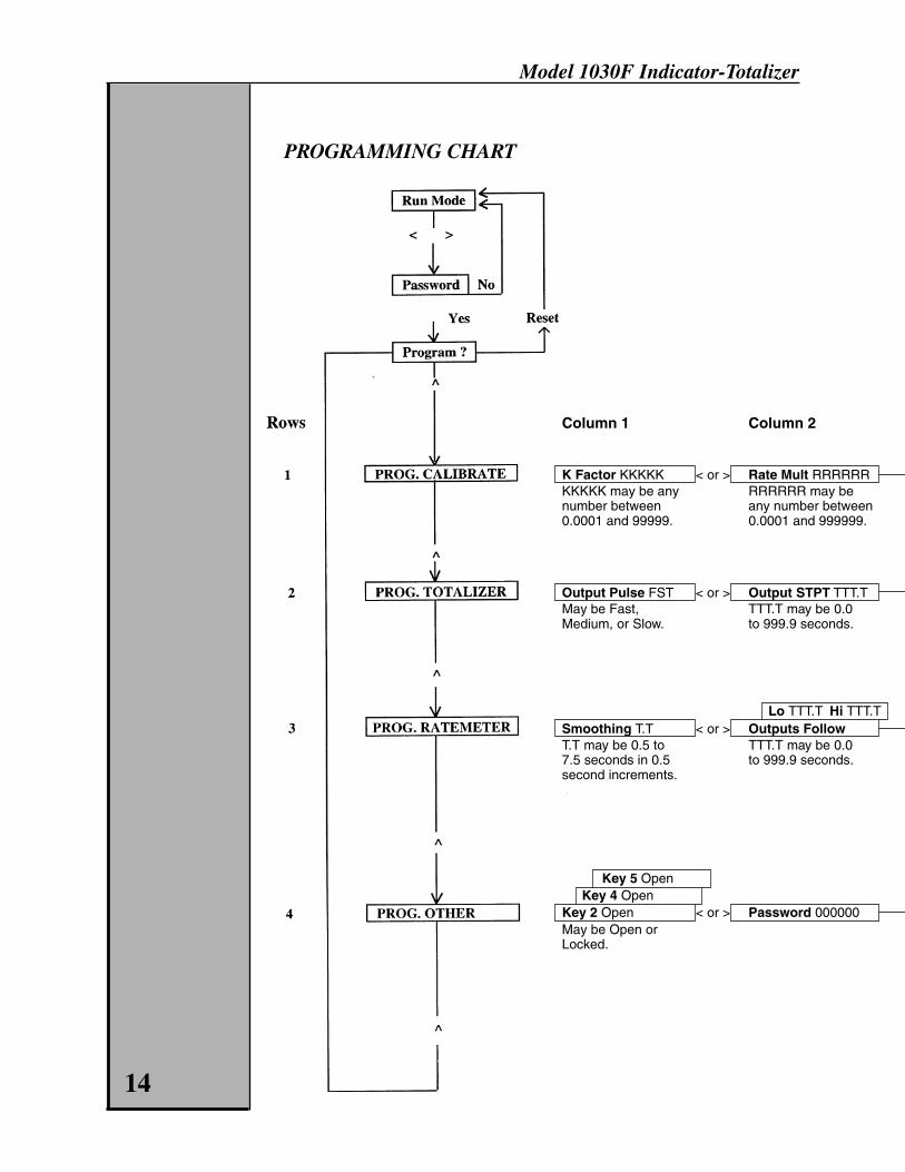
PROGRAMMINGSee Programming Chart.
Programming the Model 1030F may be done from the front panel by twomethods. The preferred method is using the menu that may be steppedthrough for making changes. The second method makes use of a rapid accesstechnique that may be quicker for a simple change but requires the program-ming diagram to be in hand.
Enter the Programming ModeSimultaneously press the < left arrow and the > right arrow keys. Notice thatthese keys have “Program” labeled immediately above them. A password maybe requested if an operator has specified a password during a previousprogramming session. The Model 1030F comes from the factory with nopassword set. Setting of the password is explained on page 17. Enter thecorrect password and press the ENT key. If an incorrect password is enteredthe message “PW ERROR” will be flashed and the unit will again ask for apassword. The user may try again if he desires. He may leave the passwordentry mode and return to the run mode by simultaneously pressing the < and >keys. If the password display is left idle, the unit will return to run modeautomatically after 15 seconds.
Once the program mode is entered, “PROGRAM ?” will be displayed.
Rapid Access Programming MethodProgram cells may be accessed directly from the “PROGRAM ?” screen byentering the row number and the column number from the Programming Charton page 14. Other cells may be accessed by pressing < and > to get the“PROGRAM ?” display and entering another row and column number.
Sequential Menu Programming MethodOnce the “PROGRAM ?” display is obtained, main menu items may beselected by pressing the ^ up arrow key. These menu items all contain theword “PROG.” See Programming Chart on page 14. Once the main menuselection has been made, the > and < keys may be used to move to submenuitems and to move back to the main menu. Then use the ^ key to selectanother main menu item.
Help MessagesWhen positioned at any submenu item, the Help key may be pressed, and ahelpful programming message will scroll across the display. After the messagehas completed, the display will return to the submenu item. If you do not wantto read the entire message, pressing any key will end the message.
Returning to Run ModeThe operator may return to the running mode by simultaneously pressing the <and > keys to obtain the “PROGRAM ?” display. Then, press the Reset key toexit the programming mode.
11

Model 1030F Indicator-Totalizer
PROGRAM MENU DESCRIPTIONSSee Programming Chart, page 14.
PROG. CALIBRATIONK FactorThe K factor is the ratio of the number of input pulses from the flow meter ortransmitter per unit of volume.
K factor = Full Scale Freq. x 60GPM
Example: 2.485 pulses per gallon
The value entered as the K factor affects both the totalizer and the rate metercalibrations. One way to increase resolution for the totalizer and rate meter isto change the K factor by a multiple of 10. Example: 0.2485. If this is done,the decimal point in both the totalizer menu and the rate meter menu shouldbe moved one place to the left. See PROG. TOTALIZER and PROG.RATEMETER.
Note: The totalizer scaled pulse output will also be 10 times greater.
Operation: Use the CLR key to enable a new entry. Use the 0-9, DP (decimalpoint), and ENT keys to enter a new K factor.
Rate MultiplierThe rate multiplier is a factor used for scaling the pulse input rate into a timeunit for flow rate indication such as “per minute” or “per day.” To calculate therate multiplier factor required for a unit, multiply the full scale flow rate by the Kfactor and divide by the full scale frequency.
Example: A given meter has a flow rang of 0-10 gpm and a K factor of 570pulses per gallon. First, calculate the frequency (pulses per second) of the flowinput signal at the full scale flow rate.
FS Freq.:
10 gal. x 570 pulses x 1 min. = 95 pulses1 min. 1 gal. 60 sec. 1 sec.
Next, multiply the full scale flow rate by the K factor and divide by the fullfrequency.
RM = (FS flow rate) x (K factor) / (FSFreq.)or
RM = 10 x 570 / 95 = 60
The readout will be in unitary gallons and unitary gpm. To obtain higherresolution for the rate meter, change RM to 600 instead of 60. Change the ratemeter decimal point to 00000.0 instead of 000000. Note that the high and lowrate set point decimals will also shift a place to the left. These values mayhave to be reentered. See PROG. RATEMETER.
Operation: Use the CLR key to enable a new entry. Use the 0-9, DP (decimalpoint), and ENT keys to enter a new rate multiplier.
4 mA Out StartThis display is used when calibrating the analog output of the unit.
12

Model 1030F Indicator-Totalizer
Operation: To calibrate the analog output, connect the analog output “+”terminal to +24 VDC out. Connect the analog output “–” terminal to groundthrough a current meter. Press the CLR key. Use the < and > keys to adjustthe output current to 4 mA and then press the ENT key. Use the ^ key to selectthe 20 mA level and repeat the process.
4 mA RateThis display is used to select the active range of the analog output. Enter theflow rate that is supposed to be represented by 4 milliamps, normally zero (0).Press the ^ key and enter the flow rate that is to be represented by 20milliamps, normally the rated full scale flow rate of the meter.
Operation: Use the ^ key to select the 4 or 20 mA rate. Use the 0-9 and ENTkeys to enter a new rate.
DiagnosticsTwo items may be tested when the diagnostics are run — the display and thecomputer itself. You may check for missing character segments in the displayby pressing the ^ key. All “8”s and decimal points should be displayed. Pressthe ^ key again and all “*”s will be displayed. Again, you should check formissing segments. Pressing the ^ key again will start the computer’sself-diagnostics test. Any errors will be flashed on the display.
Operation: Press the ^ key three times to cycle through the diagnostic tests.
PROG. TOTALIZEROutput PulseFast 125 microsecond pulse width, output 1500 pulses/second max.Medium 2 millisecond pulse width, output 200 pulses/second max.Slow 50 millisecond pulse width, 10 pulses/seconds max. frequency
Operation: Use the ^ key to select the function of the totalizer output.
Output Set PointDecide the totalizer set point output. If 0.0 is entered, the output will belatched. If 0.1 to 999.9 is entered, the output will be timed. The output willremain on, if timed, for as long as the totalizer condition exists and for thetimeout period. The timeout period may be preempted by unlatching theoutput.
Operation: Use the CLR key to enable entry of a new timeout. Use the 0-9and ENT keys to enter the timeout value of the output.
ResetThe front panel reset key can be configured to perform multiple or no functionsfor the totalizer. These functions include reset totalizer count, unlatch totalizerset point output, reset totalizer count and unlatch totalizer set point output,and none.
Operation: Use the ^ key to select the totalizer function of the Reset key.
Decimal PointThe decimal point position of the totalizer may be selected using this display.
Example: Use the ^ key to select the decimal point location for the totalizer.
Continued on page 16 13
Model 1030F Indicator-Totalizer
PROGRAMMING CHART
Column 1 Column 2
K Factor KKKKK < or > Rate Mult RRRRRRKKKKK may be any RRRRRR may benumber between any number between0.0001 and 99999. 0.0001 and 999999.
Output Pulse FST < or > Output STPT TTT.TMay be Fast, TTT.T may be 0.0Medium, or Slow. to 999.9 seconds.
Lo TTT.T Hi TTT.TSmoothing T.T < or > Outputs FollowT.T may be 0.5 to TTT.T may be 0.07.5 seconds in 0.5 to 999.9 seconds.second increments.
Key 5 OpenKey 4 Open
Key 2 Open < or > Password 000000May be Open orLocked.
14

Model 1030F Indicator-Totalizer
Column 3 Column 4 Column 5 Column 6
20 mA Out Start ? 20 mA Rate RRRRRR4 mA Out Start? < > 4 mA Rate RRRRRR < > Diagnostics
RRRRRR may benumbers less thanor equal to 999999.
Reset Unl. Out < > Dec. Pt. 000000May be None, ResetCount, Unlatch Output,or Reset and Unlatch.
Reset Unl. Out < > Dec. Pt. 000000 < > Rate at Zero TT < > Rate Header GPMMay be None or TT may be 1 to G, P, and M mayUnlatch Hi/Lo 15 seconds. be any alphabeticalAlarms. character or a
blank space
Baud BBBBB PPPPP < > ID I I I Time TTT < > Speed 400 Hz max.Baud Rate (BBBBB) I I I may be 0 to Input pulse speedmay be 300, 600, 1200, 255. TTT may be may be 40, 400, or2400, 4800, or 9600. 0, 10, 100, or 500. 7500 Hz maximums.Parity (PPPPP) maybe Space, Even,or Odd.
15

Model 1030F Indicator-Totalizer
PROG. RATEMETERSmoothingA built-in dynamic averager performs software dampening. With this, a stablereading of flow rate may be obtained from a pulsating flow system. A smooth-ing factor of 0.5 to 7.5 may be set in 0.5 increments. By setting the smoothingfactor at 0.5, no damping is performed. A smoothing factor of 7.5 provides a7.5 second time delay for 100% display settling after a change in flow rate.Instantaneous rate readings are taken and averaged to produce a singlereading to be displayed. With each rate update, the oldest reading will beincorporated into the average.
Operation: Use the ^ key to select a new rate smoothing time.
Outputs FollowThe high and low flow rate set points may operate three different ways. Theymay follow the flow rate, be latched, or be timed. If latched, set the timeoutperiod for 0.0 seconds. If timed, set the timeout from 0.1 to 999.9 seconds.The output will persist until after the responsible conditions cease and thetimeout period has expired or until the output is unlatched.
Operation: Use the ^ key to select whether the rate outputs follow the rateor are timed. If timed, use the < and > keys to select either the lo or hi rateoutput. Use the CLR key to enable a new entry. Use the 0-9 and ENT keysto enter a new output time. The output is latched if a time of 0.0 is entered.
ResetThe front panel reset key can perform either an unlatching of the rate set pointoutputs or no function at all.
Operation: Use the ^ key to select the rate meter function of the Reset key.
Decimal PointThe decimal point position of the rate meter may be selected using thisdisplay.
Operation: Use the ^ key to select the decimal point location for the rate meter.
Rate at ZeroIn absence of the flow pulse input, the rate at zero is the period that the ratemeter will show the last legitimate flow reading before showing a zero flowrate. The period may be set from 1 to 15 seconds. An ideal application to usethis function would be when flow pulse input rates are expected to be veryslow. Example: A “rate at zero” set to “15” would be useful when the pulseinput rate is expected to be as low as 1 pulse every 10 seconds. An expectedlow pulse rate of 1 pulse every 2 seconds may constitute a “rate at zero”setting of 3 to 5 seconds. For low pulse rates greater than 5 per seconds, a“rate at zero” settling of “1” is normal.
Operation: Use the CLR key to enable a new entry. Use the 0-9 keys and ENTto enter a new rate zero time.
Rate HeaderThree alphabetical characters and a blank character may be used to label theflow rate display with engineering units.
Operation: Use the > and< keys to select which location to program. Use the ^key to select the character for that location.
16

Model 1030F Indicator-Totalizer
PROG. OTHERKey 2 Open (Also, keys 4 and 5)The totalizer set point value, rate low set point value, and the rate high setpoint value may be designated as open or locked. Locking the value preventsthe changing of the set point value from the front panel unless it is firstreopened in the programming mode. This protects against unauthorizedpersons having access change the set points in critical control applications.
Operation: Use the 2, 4, or 5 keys to select which set point mode to program.Use the ^ key to select whether or not the selected set point is locked.
PasswordA password may be specified for the next entry into the programming mode. Apassword of zeros (000000) means that no password is required for programmode entry. Do not forget your password!
Operation: Use the CLR key to enable a new entry. Use the 0-9 and ENT keysto enter a new password.
Baud - - - ParityThe baud rate and parity must be specified when using the RS-485 communi-cations link. The baud rate should be chosen from 300, 600, 1200, 2400,4800, 9600, 19200. The parity may be space (none), even, or odd.
Operation: Use the CLR key to enable entry. Use the 0-9 and ENT keys toenter the communication baud rate. Use the ^ key to select odd, even, orspace parity.
ID - - - TimeThe Model 1030’s identification number must be set whenever using theRS-485 communication link. This must be a number between 0 and 255. Notwo units on the same link may have the same ID. Also, the minimum commu-nication response time for the unit must be specified. It may be selected from0, 10, 100, or 500 milliseconds. A longer time is normally given for non-time-critical applications.
Operation: Use the CLR key to enable entry. Use the 0-9 and ENT keys toenter the unit identity number from 0 to 255. Each unit on the communicationlink must have a unique number. Use the ^ key to select the minimumcommunication response time.
Input SpeedThe pulse frequency of the flow input must be specified. Three choicesare available.
Fast (7500 Hz max.) — is used for quick electronic pulses.Min. pulse width is 50 microseconds.Medium (400 Hz max.) — Min. pulse width is 1.5 milliseconds.Slow (40 Hz max.) — is recommended for contact closure inputs.Min. pulse width is 10 milliseconds.
FS Freq. = gpm x pulses per gallon60
Operation: Use the ^ key to select the count input speed.
17

Model 1030F Indicator-Totalizer
SPECIFICATIONSFlow InputsRequire npn current sinking or contact closure to ground.Internal 5.8K ohm pull-up resistor to 5 VDC
Voltage low: 0-2.2 VDCVoltage high: 2.8-24 VDCHigh speed: 0-7500 Hz; min. pulse width; 50 microsecondsMed. speed: 0-400 Hz; min. pulse width; 1.5 millisecondsLow speed: 0-40 Hz; min. pulse width; 10 millisecondsRate display: 1 Hz min.Input A: Flow inputInput B: Flow input inhibit (flow input ignored when pulled low)
Front panel control: pushbutton control (may be locked out)
Reset*:Rate meter: unlatch rate hi/lo set point outputs, or none;Totalizer: reset totalizer count, unlatch totalizer set point output, resettotalizer count and unlatch totalizer set point output, or noneNote*: When more than one function is available, the function that isitalicized is the program default. It is possible to change the functionthrough the program menu.
Control inputs: Contact closure or npn transistor pull down to groundimpedance: 5.8K ohm pull-up resistor to 5 VDClow: 0-1.0 VDC; high: 3.5-24 VDCresponse: min. low 30 millisec.; min. high 30 millisec.
Control Input 1: Unlatch totalizer set point outputControl Input 2: Reset totalizer countControl Input 3: Unlatch rate hi/lo set point outputsControl Input 4: Unlatch totalizer set point output and unlatch rate hi/lo
set point outputsControl Input 5: Reset totalizer count, unlatch totalizer set point output,
and unlatch rate hi/lo set point outputs
Power supply: 115 VAC, 50/60 Hz, 0.2 A or 18-27 VDC, 0.4 A max., 6 W max.(230 VAC or 18-27 VDC version available)
Power output: 24 VDC ±5 % at 100 mA max. for sensors and peripheralswhen unit is supplied with AC power input only
Rate meterK factor: 0.0001 to 99999Rate multiplier: 0.00001 to 999999Accuracy: ±0.05%Rate smoothing: designate 0.5 to 7.5 second dynamic averaging in
0.5 second incrementsRate update: 0.5 seconds
Current output: 4-20 mA; 100 ohm impedence; optically isolatedLoad: 1000 ohms max. at 24 VDCCompliance voltage: –12-27 VDCResponse time: 0.5 seconds (follows rate meter)Accuracy: ±0.1% at 25°C; ±0.25% over temp. rangeResolution: 0.05% (11 bits)
18

Model 1030F Indicator-Totalizer
Control outputs: npn trans. (150 mA max., 30 VDC max.)Control output 1: scaled totalizer pulse output with designated
pulse widthhigh speed: 1500 Hz. max.; 125 microsecond pulse widthmed. speed: 200 Hz. max.; 2 millisecond pulse widthlow speed: 10 Hz. max.; 50 millisecond pulse width
Control output 2: totalizer set point outputControl output 3: low rate set point outputControl output 4: high rate set point output
Note: Rate hi/lo set point output operations may either: follow theflow; be latched; or be timed from 0.1 to 999.9 seconds. The totalizerset point output operation may be either: latched; or timed from 0.1 to999.9 seconds.
CommunicationsType: RS-485 multidropBaud: 300, 600, 1200, 2400, 4800, 9600,19200Parity: space, even, or oddProtocol: Opto-22 compatible
Wiring terminals: 14 awg max., detachable
EnvironmentalOperating temperature: 32 to 131°F (0 to 55°C)Storage temperature: –40 to 158°F (–40 to 70°C)Humidity: 0 to 85% RH noncondensingPanel mount version: key pad is NEMA 4X with gasket that will seal
panel NEMA 4Wall mount version: enclosure and front panel are NEMA 4X
19

Model 1030F Indicator-Totalizer
20
DIMENSIONS
Panel Mount
Wall Mount

Model 1030F Indicator-Totalizer
21

Model 1030F Indicator-Totalizer
150 Venture BoulevardSpartanburg, SC 29306
Phone: (800) 778-9251, (864) 574-3327Fax: (864) 574-8063Repair Service: (800)778-9249Internet: www.aaliant.comE-mail: [email protected]
© 2000 Venture Measurement Co., LLC M518 Rev. B 11/00
AProduct Line