model r series installation, operation & … · tion which, if not avoided, will result in...
TRANSCRIPT

RRCC22--110000444422--99115599
IN UNITED STATES: 260 NORTH ELM ST., WESTFIELD, MA 01085 (413) 564-5515/FAX (413) 568-9613IN CANADA: 5211 CREEKBANK ROAD, MISSISSAUGA, ONT. L4W IR3 (905) 625-2991/FAX (905) 625-6610
MMOODDEELL RR SSEERRIIEESSIINNSSTTAALLLLAATTIIOONN,,OOPPEERRAATTIIOONN &&MMAAIINNTTEENNAANNCCEE
MMAANNUUAALL &&RREEPPLLAACCEEMMEENNTT
PPAARRTTSS LLIISSTTGGaass--FFiirreedd WWaatteerr CCaasstt IIrroonn BBooiilleerrss
118800,,000000 ttoo 330000,,000000 BBttuuhh IInnppuuttSSttaannddiinngg PPiilloott,, IInntteerrmmiitttteenntt PPiilloott &&
VVeenntt DDaammppeerr
SSEECCTTIIOONN 11:: BBOOIILLEERR IINNSSTTAALLLLAATTIIOONNIntroduction............................................................ 2Step 1: Locating & Setting Boiler........................... 3Step 2: Installing/Purging Water Piping................. 5Step 3: Venting Boiler............................................ 8Step 4: Installing/Testing Gas Piping..................... 10Step 5: Wiring Boiler.............................................. 11
SSEECCTTIIOONN 22:: SSTTAARRTT--UUPP && OOPPEERRAATTIIOONNSafety Controls...................................................... 17Start-Up & Adjustments......................................... 17
SSEECCTTIIOONN 33:: MMAAIINNTTEENNAANNCCEEWater Treatment.................................................... 20Freeze Protection................................................... 20Before Each Heating Season................................ 20How To Change Orifices........................................ 21Troubleshooting..................................................... 21
Appendix A (French Vent Damper Translation)..... 22
Replacement Parts List.......................................... 23

2
AANNSSII//AASSMMEE CCOODDEE CCOOMMPPLLIIAANNCCEE:: Installation mustconform to requirements of authority having jurisdictionor, in absence of such requirements, to National FuelGas Code ANSI Z223.1-latest edition and to NationalElectric Code NFPA-70-latest edition. Where required byauthority having jurisdiction, installation must also con-form to Standard for Controls and Safety Devices forAutomatically Fired Boilers, ANSI/ASME CSD-1.
For Canada, the installation must be in accordance withStandards CAN/CGA-B149 (.1 or .2) Installation Codesfor Gas Burning Appliances and Equipment and withStandard C.S.A. C22.1 Canadian Electrical Code, Part 1and Part 2, and/or local codes.
BBOOIILLEERR SSHHIIPPMMEENNTT:: Each boiler is shipped in a singlecarton. There is a vent damper packed separately withthe boiler (for model R-300 vent damper is optional)
MMOODDEELL RR BBOOIILLEERR DDIIMMEENNSSIIOONNSS
D
*LOCATED IN FRONT ON MODELS R-180C AND R-210C
PRESS. RELIEF VALVE
TEMP./PRESS. INDICATOR
HI-LIMIT AQUASTAT
7"
GAS VALVE
*2" SUPPLY
BOILERMODEL
R-300BR-250CR-210CR-180C 28-1/4" 58-5/8" 7"21-7/8"
DIMENSIONSA B C D
28-1/4"
32-1/4"28-7/8"
61-7/8"65-5/8"
7"7"8"
32-1/4"29-3/8" 66-1/8"
25-1/8"
B
2" RETURN
9-1/2"
9-1/2"
12"
SPILL SWITCH
ROLLOUTSWITCH
NOTE: SPILL & ROLLOUTSWITCHES USED ONR-180 THRU R-250.
VENT DAMPER
3 5/8"
C
36 3/4"
21 1/4"
A
25 1/2"
DDAANNGGEERR:: IInnddiiccaatteess aann iimmmmiinneennttllyy hhaazzaarrddoouuss ssiittuuaa--ttiioonn wwhhiicchh,, iiff nnoott aavvooiiddeedd,, wwiillll rreessuulltt iinn ddeeaatthh,, sseerrii--oouuss iinnjjuurryy oorr ssuubbssttaannttiiaall pprrooppeerrttyy ddaammaaggee..
WWAARRNNIINNGG:: IInnddiiccaatteess aa iimmmmiinneennttllyy hhaazzaarrddoouuss ssiittuuaa--ttiioonn wwhhiicchh,, iiff nnoott aavvooiiddeedd,, ccoouulldd rreessuulltt iinn ddeeaatthh,, sseerrii--oouuss iinnjjuurryy oorr ssuubbssttaannttiiaall pprrooppeerrttyy ddaammaaggee..
CCAAUUTTIIOONN:: IInnddiiccaatteess aa iimmmmiinneennttllyy hhaazzaarrddoouuss ssiittuuaa--ttiioonn wwhhiicchh,, iiff nnoott aavvooiiddeedd,, mmaayy rreessuulltt iinn mmiinnoorr iinnjjuurryyoorr pprrooppeerrttyy ddaammaaggee..
NNOOTTEE:: UUsseedd ttoo nnoottiiffyy ooff ssppeecciiaall iinnssttrruuccttiioonnss oonniinnssttaallllaattiioonn,, ooppeerraattiioonn oorr mmaaiinntteennaannccee wwhhiicchh aarreeiimmppoorrttaanntt ttoo eeqquuiippmmeenntt bbuutt nnoott rreellaatteedd ttoo ppeerrssoonnaalliinnjjuurryy hhaazzaarrddss..
The following terms are used throughout this manual to bring attention to the presence of potential hazards or toimportant information concerning the product:
WWAARRNNIINNGG:: IInnssttaalllleerrss mmuusstt ffoollllooww llooccaall rreegguullaattiioonnsswwiitthh rreessppeecctt ttoo tthhee iinnssttaallllaattiioonn ooff CCOO ddeetteeccttoorrss aannddffoollllooww tthhee mmaannuuffaaccttuurreerr''ss ssttaatteedd mmaaiinntteennaanncceesscchheedduullee ffoorr tthhiiss bbooiilleerr!!
AATTTTEENNTTIIOONN:: OObbsseerrvveerr lleess rrèègglleemmeennttss rrèèggiioonnaall àà ll''ee--ggaarrdd ddeess ddéétteecctteeuurrss ddee mmoonnooxxyyddee ddee ccaarrbboonnee eettoobbsseerrvveerr eennttrreettiieenn ddee mmaannuuffaaccttuurriieerr ppoouurr cceetttteecchhaauuddiièèrree!!
3
SSEECCTTIIOONN 11:: BBOOIILLEERR IINNSSTTAALLLLAATTIIOONN
SSTTEEPP 11:: LLOOCCAATTIINNGG && SSEETTTTIINNGG TTHHEE BBOOIILLEERR
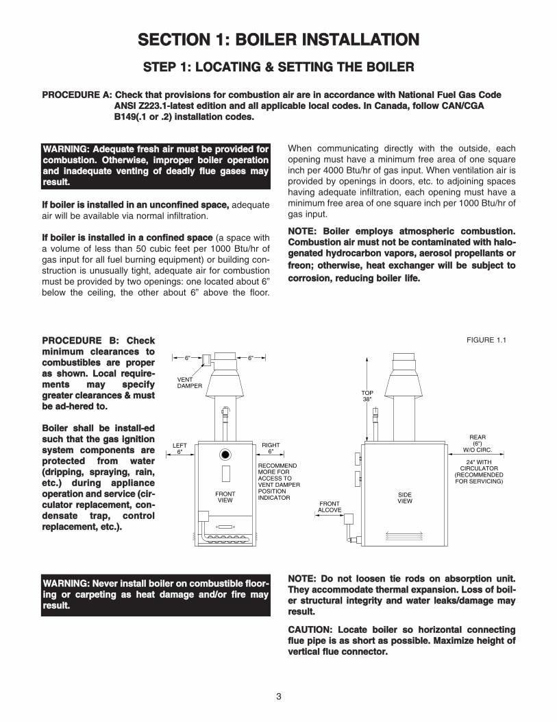
PPRROOCCEEDDUURREE AA:: CChheecckk tthhaatt pprroovviissiioonnss ffoorr ccoommbbuussttiioonn aaiirr aarree iinn aaccccoorrddaannccee wwiitthh NNaattiioonnaall FFuueell GGaass CCooddeeAANNSSII ZZ222233..11--llaatteesstt eeddiittiioonn aanndd aallll aapppplliiccaabbllee llooccaall ccooddeess.. IInn CCaannaaddaa,, ffoollllooww CCAANN//CCGGAABB114499((..11 oorr ..22)) iinnssttaallllaattiioonn ccooddeess..
IIff bbooiilleerr iiss iinnssttaalllleedd iinn aann uunnccoonnffiinneedd ssppaaccee,, adequateair will be available via normal infiltration.
IIff bbooiilleerr iiss iinnssttaalllleedd iinn aa ccoonnffiinneedd ssppaaccee (a space witha volume of less than 50 cubic feet per 1000 Btu/hr ofgas input for all fuel burning equipment) or building con-struction is unusually tight, adequate air for combustionmust be provided by two openings: one located about 6”below the ceiling, the other about 6” above the floor.
When communicating directly with the outside, eachopening must have a minimum free area of one squareinch per 4000 Btu/hr of gas input. When ventilation air isprovided by openings in doors, etc. to adjoining spaceshaving adequate infiltration, each opening must have aminimum free area of one square inch per 1000 Btu/hr ofgas input.
NNOOTTEE:: BBooiilleerr eemmppllooyyss aattmmoosspphheerriicc ccoommbbuussttiioonn..CCoommbbuussttiioonn aaiirr mmuusstt nnoott bbee ccoonnttaammiinnaatteedd wwiitthh hhaalloo--ggeennaatteedd hhyyddrrooccaarrbboonn vvaappoorrss,, aaeerroossooll pprrooppeellllaannttss oorrffrreeoonn;; ootthheerrwwiissee,, hheeaatt eexxcchhaannggeerr wwiillll bbee ssuubbjjeecctt ttooccoorrrroossiioonn,, rreedduucciinngg bbooiilleerr lliiffee..
FRONTALCOVE
REAR(6")
W/O CIRC.
24" WITHCIRCULATOR
(RECOMMENDEDFOR SERVICING)
RECOMMENDMORE FORACCESS TOVENT DAMPERPOSITIONINDICATOR
VENTDAMPER
6" 6"
LEFT6"
SIDEVIEW
FRONTVIEW
TOP38"
RIGHT6"
FIGURE 1.1PPRROOCCEEDDUURREE BB:: CChheecckkmmiinniimmuumm cclleeaarraanncceess ttooccoommbbuussttiibblleess aarree pprrooppeerraass sshhoowwnn.. LLooccaall rreeqquuiirree--mmeennttss mmaayy ssppeecciiffyyggrreeaatteerr cclleeaarraanncceess && mmuussttbbee aadd--hheerreedd ttoo..
BBooiilleerr sshhaallll bbee iinnssttaallll--eeddssuucchh tthhaatt tthhee ggaass iiggnniittiioonnssyysstteemm ccoommppoonneennttss aarreepprrootteecctteedd ffrroomm wwaatteerr((ddrriippppiinngg,, sspprraayyiinngg,, rraaiinn,,eettcc..)) dduurriinngg aapppplliiaanncceeooppeerraattiioonn aanndd sseerrvviiccee ((cciirr--ccuullaattoorr rreeppllaacceemmeenntt,, ccoonn--ddeennssaattee ttrraapp,, ccoonnttrroollrreeppllaacceemmeenntt,, eettcc..))..
NNOOTTEE:: DDoo nnoott lloooosseenn ttiiee rrooddss oonn aabbssoorrppttiioonn uunniitt..TThheeyy aaccccoommmmooddaattee tthheerrmmaall eexxppaannssiioonn.. LLoossss ooff bbooiill--eerr ssttrruuccttuurraall iinntteeggrriittyy aanndd wwaatteerr lleeaakkss//ddaammaaggee mmaayyrreessuulltt..
CCAAUUTTIIOONN:: LLooccaattee bbooiilleerr ssoo hhoorriizzoonnttaall ccoonnnneeccttiinnggfflluuee ppiippee iiss aass sshhoorrtt aass ppoossssiibbllee.. MMaaxxiimmiizzee hheeiigghhtt ooffvveerrttiiccaall fflluuee ccoonnnneeccttoorr..
WWAARRNNIINNGG:: AAddeeqquuaattee ffrreesshh aaiirr mmuusstt bbee pprroovviiddeedd ffoorrccoommbbuussttiioonn.. OOtthheerrwwiissee,, iimmpprrooppeerr bbooiilleerr ooppeerraattiioonnaanndd iinnaaddeeqquuaattee vveennttiinngg ooff ddeeaaddllyy fflluuee ggaasseess mmaayyrreessuulltt..
WWAARRNNIINNGG:: NNeevveerr iinnssttaallll bbooiilleerr oonn ccoommbbuussttiibbllee fflloooorr--iinngg oorr ccaarrppeettiinngg aass hheeaatt ddaammaaggee aanndd//oorr ffiirree mmaayyrreessuulltt..

4
BAFFLEGRID
DOME6"
4" HOLLOW CLAY TILE (TWO COURSES) OPENINGS THRUBLOCKS IN TOP COURSE TO BE AT 90 ANGLE TO OPENINGSTHRU BOTTOM COURSE
0
22 GAUGESHEETMETAL
FLOOR
6" OVERHANGOF BLOCK ANDSHEETMETALALL AROUND
FIGURE 1.2A FIGURE 1.2B
PPRROOCCEEDDUURREE DD:: IInnssttaallll jjaacckkeett..
1. Unpack jacket parts from carton and check that quan-tity is correct: two side panels, one rear panel, one lefttop panel and one right top panel (see Figure 1.3).
2. Stand left and right side panels in place and fasten tofront panel with screws provided. Fasten side panels torear panel in same manner.
LEFT TOP PANEL
FRONT PANEL(BOILER MOUNTED)
RIGHT SIDE PANEL
RIGHT TOP PANEL
LEFT SIDE PANEL
REAR PANEL
REMOVE KNOCK-OUT
ASSEMBLY SCREW
FIGURE 1.3
3. Lock left and right halves of top panel together and fas-ten to side panels with screws provided.
PPRROOCCEEDDUURREE CC:: CChheecckk ccoommppoonneenntt ppoossiittiioonniinngg..
1. Remove all packing material from boiler.
2. Install boiler on non-combustible flooring only, unlesslocal codes permit use and fabrication of a recommend-ed fireproof base (see Figure 1.2A).
3. Check that burners and controls are in the properposition.
4. Check proper seating of baffle grid inside of domeopening (see Figure 1.2B).

5
PPRROOCCEEDDUURREE BB:: IInnssttaallll ssuuppppllyy aanndd rreettuurrnn wwaatteerrppiippiinngg.. FFoorr MMooddeellss RR--118800CC && 221100CC ssuuppppllyy oouuttlleett iissaatt ffrroonntt ooff bbooiilleerr aanndd rreelliieeff vvaallvvee ppiippiinngg iiss aatt rreeaarr ooffbbooiilleerr..
SHUT-OFFVALVE
VERTICAL EXPANSION TANKARRANGEMENT (PREFERRED)
DRAIN VALVE
SHUT-OFFVALVE
PRESS.RELIEFVALVE AIR VENT
SHUT-OFFVALVE
PRESSUREREDUCING(FILL) VALVE
SHUT-OFFVALVES
CIRCULATOR
DRAIN VALVE
FIGURE 1.5
IIff bbooiilleerr iiss iinnssttaalllleedd aabboovvee lleevveell ooff rraaddiiaattiioonn,, aa lloowwwwaatteerr ccuutt--ooffff mmuusstt bbee uusseedd..
AALLLL EEXXTTEERRNNAALL PPIIPPIINNGG MMUUSSTT BBEE SSUUPPPPOORRTTEEDD BBYYHHAANNGGEERRSS,, NNOOTT BBYY BBOOIILLEERR AACCCCEESSSSOORRIIEESS..
HORIZONTAL EXPANSIONTANK ARRANGEMENT
DRAIN VALVE
SSTTEEPP 22:: IINNSSTTAALLLLIINNGG && PPUURRGGIINNGG WWAATTEERR PPIIPPIINNGG
NNOOTTEE:: BBooiilleerr mmuusstt nnoott bbee uusseedd wwiitthhoouutt ffoorrccee cciirrccuu--llaattiioonn,, aass oovveerrhheeaattiinngg oorr ffaaiilluurree ooff ccaasstt iirroonn sseeccttiioonnss mmaayy rreessuulltt..
PPRROOCCEEDDUURREE AA:: IInnssttaallll pprreessssuurree rreelliieeff vvaallvvee aannddrreelliieeff vvaallvvee ddiisscchhaarrggee ppiippiinngg.. FFoorr MMooddeell RR--330000BBssuuppppllyy oouuttlleett iiss aatt rreeaarr aanndd rreelliieeff vvaallvvee ppiippiinngg iiss aattffrroonntt ooff bbooiilleerr..
RReelliieeff VVaallvvee DDiisscchhaarrggee PPiippiinngg:: MMuusstt tteerrmmiinnaattee 66””aabboovvee fflloooorr && bbee ssaammee ssiizzee oorr llaarrggeerr tthhaann vvaallvvee oouuttlleett..
PRESS. RELIEF VALVE
AIRVENT
RELIEF VALVE DISCHARGEPIPING
FIGURE 1.4
WWAARRNNIINNGG:: NNoo vvaallvvee ooff aannyy ttyyppee mmaayy bbee iinnssttaalllleeddbbeettwweeeenn bbooiilleerr && rreelliieeff vvaallvvee ttoo pprreevveenntt aacccciiddeennttaalleexxpplloossiioonn ffrroomm oovveerr--pprreessssuurree..
CCAAUUTTIIOONN:: PPiippiinngg mmuusstt bbee iinnssttaalllleedd ffrroomm rreelliieeff vvaallvveeddiisscchhaarrggee ssoo tthheerree wwiillll bbee nnoo ddaannggeerr ooff ssccaallddiinngg ppeerr--ssoonnnneell..

6
SUPPLY RETURN
50%120° F
100%140° F
100%160° F
50%160° F
50%160° F
SYSTEMBYPASS
FIGURE 1.6
SUPPLY RETURN
50%120° F
100%140° F
100%160° F
50%160° F
50%160° F
PUMP AWAYBYPASS
SUPPLY RETURN
100%120° F
200%140° F
200%160° F
100%160° F
100%160° F
PUMPEDBYPASS
FIGURE 1.7
FIGURE 1.8
CCAAUUTTIIOONN:: TToo pprreevveenntt ddaammaaggee dduuee ttoo eexxcceessssiivvee ccoonn--ddeennssaattiioonn,, oonnee ooff tthhee ffoolllloowwiinngg ppiippiinngg ooppttiioonnss sshhoouullddbbee uusseedd..
SSYYSSTTEEMM BBYYPPAASSSSFor systems using a circulator on the return as either asingle zone, or multiple zones with zone valves, install asystem bypass line between the supply and return on thesuction side of the circulator (see Figure 1.6). Install ametering valve in this bypass line to regulate the amountof flow that will be diverted to the return. A plug valveoffers the best control for this application. Although othervalves may be less expensive, a plug valve will be easierto set accurately.
In the absence of a flow indicator, set the metering valveusing temperature as a guide. The accompanying dia-gram suggests one scenario. This addition requires onlytwo tees, a plug valve, and a small amount of pipe andoffers the simplest approach to reliably control condensa-tion. For this system and those that follow, be aware thatyou are using a percentage of the pump capacity toblend, but the friction loss for the entire pump flow hasbeen reduced. In most cases, the standard pump pack-aged with the boiler has enough capacity to feed thebaseboard distribution system and the bypass line.
PPUUMMPP AAWWAAYY BBYYPPAASSSSFor systems that use a single circulator to pump awayfrom the boiler, the bypass should be installed on the dis-charge side of the circulator (see Figure 1.7). Full tem-perature water supplies the baseboard distribution sys-tem as before. Half of the circulator’s volume movesthrough the bypass, blending and heating the coolerreturn water. Again, the cost of installing the bypass issmall and setting it by temperature can be accomplishedwith a contact thermometer.
PPUUMMPPEEDD BBLLEENNDDAn additional circulator can also be used to provide areturn water temperature blend. This method works wellwith systems with multiple zones with circulators (seeFigure 1.8). The dedicated bypass circulator provides astrong blending flow without diminishing the flow avail-able to any heating zone. Any residentially sized circula-tor is adequate for this purpose.
Each of these bypass solutions also has the added ben-efit of increasing circulation in the boiler which will maxi-mize tankless coil output and increase the accuracy oftemperature sensing controls.

7
PPRROOCCEEDDUURREE DD:: CCoommpplleetteellyy ffiillll && ppuurrggeehheeaattiinngg ssyysstteemm.. MMaakkee ssuurree tthhaatt aallll hheeaatt--iinngg ssyysstteemm mmaannuuaall aaiirr vveennttss aarree cclloosseedd..
1. Check flow direction arrows on hydroniccomponents are facing in proper direction.
2. Attach hose to drain valve “B” and closevalve “A”. Open valves “C”, “D”, “E” and “F”and drain valve “B”. Fill system with wateruntil water runs out of the hose in a steadystream (no visible air bubbles).
3. Close valves “C” and “D”. Open valve “A”.When water runs out of the hose in a steadystream (no visible air bubbles), close drainvalve “B”.
4. Open valves “C” and “D”.
VALVE “C”
VALVE “B”VALVE “A”
VALVE “D”
VALVE “E”
VALVE “F”
FIGURE 1.11
PPRROOCCEEDDUURREE CC:: FFoorr ccoommbbiinnaattiioonn hheeaattiinngg aanndd ccooooll--iinngg iinnssttaallllaattiioonnss oonnllyy..
If a hot water boiler is installed in connection with a waterchiller, the chilled water must be piped in parallel with theboiler, using appropriate valves to prevent the chilledmedium from entering the boiler (see Figure 1.10). Whenboilers are connected to heating coils located in air han-dling units where they may be exposed to refrigerated aircirculation, such boiler piping system shall be equippedwith flow-control valves or other means to prevent gravi-ty circulation of the boiler water during the cooling cycle.
NOTE: VALVES "H" OPENED ON HEATING WITH "C" VALVES CLOSED REVERSE PROCEDURE ON COOLING.
EXP. TANKVENT ROOM
UNIT
DRAINCHILLER
BOILER
H
CPUMP
RELIEFVALVE
FILLVALVE
DRAIN
C
H
BOILERFIGURE 1.10
FFOORR WWAATTEERR TTRREEAATTMMEENNTT && FFRREEEEZZEE PPRROOTTEECCTTIIOONN RREEQQUUIIRREEMMEENNTTSS,,SSEEEE ““SSEECCTTIIOONN 33:: MMAAIINNTTEENNAANNCCEE”” IINN TTHHIISS MMAANNUUAALL
reverseaquastat
N.O.
T
Tt'stat
GV
115 volts
24 volts
circulator
operatingaquastat
N.C.
REVERSEAQUASTAT
SET AT 120° FFIGURE 1.9
RREEVVEERRSSEE AACCTTIINNGG AAQQUUAASSTTAATTSSAn alternative for existing systems experiencing conden-sation that does not require re-piping the boiler utilizes areverse acting aquastat, one that makes on temperaturerise. This approach works best in single zone systems.Wired in series with the circulator, this control holds the cir-culator off until the boiler reaches an acceptable tempera-ture and then starts system circulation (see Figure 1.9).
The most commonly available reverse acting aquastat isa Honeywell L4006B. The aquastat should be mounted inan immersion well directly installed in the boiler. The useof heat conductive grease (Honeywell part # 972545) inthe immersion well is strongly recommended for fast andaccurate temperature response. Set this adjustableaquastat to make at no less than 130° F. While thismethod can cause the circulator to cycle more frequently,setting the aquastat’s differential to the maximum (25-30°F) will minimize short cycling.

8
SSTTEEPP 33:: VVEENNTTIINNGG TTHHEE BBOOIILLEERR
NNOOTTEE:: FFoorr bbooiilleerrss eeqquuiippppeedd wwiitthh iinntteerrmmiitttteenntt ppiilloottiinnssttaallll pplluugg ssuupppplliieedd iinn ddaammppeerr ppaacckkaaggee iinnttoo ddaammppeerrvvaannee hhoollee.. FFoorr ssttaannddiinngg ppiilloott bbooiilleerrss ddiissccaarrdd pplluugg..AAddddiittiioonnaall vveennttiinngg aanndd cchhiimmnneeyy rreeqquuiirreemmeennttss aarreepprroovviiddeedd oonn ppaaggee 99..
PPRROOCCEEDDUURREE BB:: IInnssttaallll vveenntt ddaammppeerr.. ((FFoorr FFrreenncchh vveerrssiioonn,, sseeee AAppppeennddiixx AA aatt rreeaarr ooff mmaannuuaall..))
FLOW DIRECTIONARROW POINTS UP
MOUNTVENT DAMPEROVERDRAFTHOOD
MAKE SUREMOTOR ISLOCATEDON LEFT SIDE
11.. MMoouunntt ddaammppeerr oonn ttoopp ooff ddrraafftt hhoooodd..
FIGURE 1.13
ATTACH LOWERPORTION OFVENT DAMPERTO DRAFTHOODWITH 1/2" ORSHORTER SCREWSOR POP RIVETS
22.. SSeeccuurree ddaammppeerr ttoo ddrraafftt hhoooodd..
FIGURE 1.14
OPEN
OPEN
1 REMOVESHIPPINGCLIP 2 OBSERVE
DAMPERROTATESTO OPENPOSITIONWITHOUTOBSTRUCTION
33.. CChheecckk ddaammppeerr ooppeerraattiioonn..
FIGURE 1.15PLUG INTO MOLEXRECEPTACLE ON FRONTOF BOILER
PLUG INTO MOLEXRECEPTACLE INSIDEDAMPER MOTOR
VENTDAMPERWIREHARNESS
44.. CCoonnnneecctt wwiirree hhaarrnneessss..
FIGURE 1.16
PPRROOCCEEDDUURREE AA:: MMoouunntt ddrraafftt hhoooodd aanndd ssppiillll sswwiittcchh oonnbbooiilleerr..
1. Install draft hood on boiler. If draft hood shroud has ahole near the relief opening, mount draft hood so holefaces to the front of the boiler.
2. R-C boilers are equipped with factory-mounted spillswitch harness/mounting bracket as-sembly; spill switchis provided in bag on boiler front.
3. Install mounting bracket on outside surface of drafthood shroud with the screws provided (HARNESS MUSTBE ON OUTSIDE OF SHROUD). Install spill switch inhole in shroud (on outside surface) with the screws pro-vided.
4. Plug wiring leads from harness/bracket assembly ontoflat terminals on spill switch.
NNOOTTEE:: BBooiilleerr wwiillll nnoott ooppeerraattee uunnlleessss wwiirriinngg lleeaaddss ttoossppiillll sswwiittcchh aarree ccoonnnneecctteedd..
INSTALLSWITCH
IN OPENINGON DRAFTHOOD
CONNECTWIRE
LEADS
INSTALLMOUNTINGBRACKET
ON DRAFTHOOD
FIGURE 1.8
DDAANNGGEERR:: DDrraafftt hhoooodd aanndd vveenntt oouuttlleett mmuusstt nnoott bbeeaalltteerreedd,, aass pprrooppeerr ooppeerraattiioonn wwoouulldd bbee jjeeooppaarrddiizzeedd;;ffllaammee rroolllloouutt,, ffiirree oorr ccaarrbboonn mmoonnooxxiiddee ppooiissoonniinnggwwiillll rreessuulltt..
DDAANNGGEERR:: OOnnllyy tthhee bbooiilleerr mmaayy bbee sseerrvveedd bbyy tthhee vveenntt ddaammppeerr.. DDoo nnoott uussee iitt ttoo vveenntt aann aaddddiittiioonnaall aapppplliiaannccee;;tthhiiss wwiillll ccaauussee ffiirree oorr ccaarrbboonn mmoonnooxxiiddee ppooiissoonniinngg..

9
AADDDDIITTIIOONNAALL VVEENNTTIINNGG RREEQQUUIIRREEMMEENNTTSS:: When connectingto gas vents or chimneys, vent installations shall be in accor-dance with Part 7, Venting of Equipment, of the National FuelGas Code, ANSI Z223.1-latest edition, or applicable provisionsof the local building codes.
Vent connectors serving appliances vented by natural draftshall not be connected into any portion of mechanical draft sys-tems operating under positive pressure.
When two or more appliances vent into a common flue, thearea of the common flue should be at least equal to the area ofthe largest flue plus 50% of the areas of the additional flue orvent connectors.
When an existing boiler is removed from a common ventingsystem, common venting system is likely to be too large forproper venting of appliances remaining connected to it. At timeof removal of existing boiler, following steps shall be followedwith each appliance remaining connected to the common vent-ing system placed in operation, while other appliances remain-ing connected to common venting system are not in operation:
1. Seal all unused openings in common vent-ing system.
2. Visually inspect the venting system for prop-er size and horizontal pitch and determinethere is no blockage or restriction, leakage,corrosion and other deficiencies which couldcause an unsafe condition.
3. Insofar as is practical, close all buildingdoors and windows and all doors between thespace in which the appliances remaining con-nected to the common venting system arelocated and other spaces of the building. Turnon clothes dryers and any appliance not con-nected to the common venting system. Turn onany exhaust fans, such as range hoods andbathroom exhausts, so they will operate atmaximum speed. Do not operate a summerexhaust fan. Close fireplace dampers.
4. Place in operation the appliance being in-spect-ed. Follow the lighting instructions. Ad-just ther-mostat so appliance will operate continuously.
5. Test for spillage at draft hood relief openingafter 5 minutes of main burner operation. Usethe flame of a match or candle, or smoke fromcigarette, cigar or pipe.
6. After it has been determined that each ap-pli-ance remaining connected to common ventingsystem properly vents when tested as outlinedabove, return doors, windows, exhaust fans,fireplace dampers and any other gas-burningappliance to previous conditions of use.
7. Any improper operation of the common vent-ing system should be corrected so installationconforms with the National Fuel Gas Code,ANSI Z223.1-latest edition. When resizing anyportion of the common venting system, thecommon venting system should be resized to
approach the minimum size as determined using the appropri-ate tables in Appendix G in the National Fuel Gas Code, ANSIZ223.1-latest edition. For Canada, the provisions of CAN/CGAB149(.1 or .2) shall apply.
AADDDDIITTIIOONNAALL CCHHIIMMNNEEYY RREEQQUUIIRREEMMEENNTTSS:: Chimney condi-tion is of paramount importance for a safe and efficient boilerinstallation. All installations must include a chimney inspectionby a qualified individual or agency. Chimney construction mate-rials must be compatible with the fuel being used.
Particular attention should be paid on all oil-to-gas conversions.Soot may have accumulated in chimney and/or degraded chim-ney liner. Most utilities require complete chimney cleaning.Others may require installation of new liner, spill switches orother chimney upgrades. Check with local utility for requiredsafety precautions.
MAXIMUM6-FT
APART
PITCH 1/4"PER FOOT
SECUREFLUE PIPETO VENTDAMPER
USE VENT SUPPORT(S) AS REQUIRED TO PREVENT SAGGING
INSTALLFLUSHWITH
INSIDECHIMNEY
LINERSEALWITH
FURNACECEMENT
SINGLE WALLOR TYPE BFLUE PIPER-180 = 7"R-210 = 7"R-250 = 7"R-300 = 8"
PPRROOCCEEDDUURREE CC:: IInnssttaallll fflluuee ppiippee bbeettwweeeenn vveenntt ddaammppeerr aannddcchhiimmnneeyy ((66”” mmiinniimmuumm cclleeaarraannccee rreeqquuiirreeddbbeettwweeeenn fflluuee ppiippee aanndd ccoommbbuussttiibblleess))..
FIGURE 1.17
DDAANNGGEERR:: AA cchhiimmnneeyy wwhhiicchh ddooeess nnoott mmeeeett mmooddeerrnnssaaffeettyy ssttaannddaarrddss wwiillll rreessuulltt iinn aa ffiirree oorr ddeeaaddllyy ccaarrbboonnmmoonnooxxiiddee ppooiissoonniinngg ooff tthhee bbuuiillddiinngg rreessiiddeennttss..

10
PPRROOCCEEDDUURREE AA:: SSeelleecctt ggaass ppiippee ssiizzee wwhhiicchh wwiillll rreessuulltt iinn aa pprreessssuurree ddrroopp ooff lleessss tthhaann 00..33”” WW..CC.. ffoorr nnaattuurraallggaass oorr 00..55”” WW..CC.. ffoorr pprrooppaannee,, ffoolllloowwiinngg eexxaammppllee bbeellooww..
EExxaammppllee:: Boiler Model R-180C is to be installed. Distance from existing gas meter to installation site is 20 ft. Whatpipe size must be used? Local utility indicates heating value of natural gas being supplied is 1020 Btu per cu.ft.Determine cubic feet of gas per hour for above boiler model:
118800,,000000 BBttuu ppeerr hhoouurr = 176.4 cu.ft. per hour1020 Btu per cu.ft.
1. Find 20 ft. in upper portion of the table for natural gas under “Length of Pipe, Feet” heading.2. Moving down the column, match required capacity. Higher capacity acceptable. In our case it is 190 cu.ft.3. Move to left-hand column “Nominal Iron Pipe Size, Inches”; read required pipe size. In our case it is 3/4”.
FIGURE 1.18
SSTTEEPP 44:: IINNSSTTAALLLLIINNGG && TTEESSTTIINNGG GGAASS PPIIPPIINNGG
Maximum Capacity of Pipe in Cubic Feet of Natural Gas per Hour for Gas Pressures of0.5 Psig or Less and a Pressure Drop of 0.3 Inch Water Column
(Based on a 0.60 Specific Gravity Gas)
NominalIron Pipe
Size,Inches
InternalDiameter,
Inches
Length of Pipe, Feet
10
3272
132278520
1,0501,6003,0504,8008,500
17,500
20
224992
190350730
1,1002,1003,3005,900
12,000
30
184073
152285590890
1,6502,7004,7009,700
40
153463
130245500760
1,4502,3004,1008,300
50
143056
115215440670
1,2702,0003,6007,400
60
122750
105195400600
1,1501,8503,2506,800
70
11254696
180370560
1,5001,7003,0006,200
80
11234390
170350530990
1,6002,8005,800
90
10224084
160320490930
1,5002,6005,400
100
9213879
150305460870
1,4002,5005,100
125
8183472
130275410780
1,2502,2004,500
150
8173164
120250380710
1,1302,0004,100
175
7152859
110225350650
1,0501,8503,800
200
6142655
100210320610980
1,7003,500
1/4"3/8"1/2"3/4"
1"1-1/4"1-1/2"2"2-1/2"3"4"
.326
.493
.622
.8241.0491.3801.6102.0672.4693.0264.026
Maximum Capacity of Pipe in Thousands of Btu per Hour of Undiluted LiquefiedPetroleum Gases (at 11 Inches Water Column Inlet Pressure)
(Based on a Pressure Drop of 0.5 Inch Water Column)
NominalIron Pipe
Size,Inches
Length of Pipe, Feet
10
275567
1071220533076221
20
189393732
149622994331
30
152315590
121218583465
40
129267504
103915592992
50
114237448937
14172646
60
103217409834
12752394
70
96196378771
11802205
80
89185346724
10862047
90
83173322677
10231921
100
78162307630967
1811
125
69146275567866
1606
150
63132252511787
1498
1/2"3/4"
1"1-1/4"1-1/2"2"

11
DDAANNGGEERR:: BBeeffoorree ppllaacciinngg ggaass ppiippiinngg iinnttoo sseerrvviiccee,, ccaarreeffuullllyy tteesstt iitt ttoo aassssuurree eevveerryy jjooiinntt iiss ggaass ttiigghhtt..BBuubbbbllee tteesstt aallll jjooiinnttss wwiitthh aa ssooaapp ssoolluuttiioonn.. NNEEVVEERR TTEESSTT WWIITTHH AANN OOPPEENN FFLLAAMMEE AASS FFIIRREE OORR EEXXPPLLOO--SSIIOONN MMAAYY RREESSUULLTT.
For any pressure testing in excess of 1/2 psi, the boilerand its individual shutoff valve must be isolated from thepiping system by disconnecting them and capping theoutlet(s). For any pressure testing equal to or less than1/2 psi, the boiler must be isolated from the piping sys-tem by closing its manual shutoff valve.
Minimum pressure required at the gas valve inlet is 5”W.C. for natural gas and 11” W.C. for propane. Maximumpressure allowable at the gas valve inlet is 12” W.C. If thegas pressure is above this limit, a pressure regulatormust be installed. If the gas pressure is below these lim-its, contact the local utility.
PPRROOCCEEDDUURREE CC:: TTeesstt ggaass ppiippiinngg..
WWHHEENN TTEESSTTIINNGG IISS CCOOMMPPLLEETTEEDD,, CCLLOOSSEE MMAAIINN GGAASS SSHHUUTT--OOFFFF VVAALLVVEE&& SSEETT BBOOIILLEERR CCOOMMBBIINNAATTIIOONN GGAASS VVAALLVVEE IINN ““OOFFFF”” PPOOSSIITTIIOONN..
PPRROOCCEEDDUURREE BB:: CCoonnnneecctt ggaass ppiippiinngg ffrroomm mmeetteerr ttoobbooiilleerr ffoolllloowwiinngg ggoooodd ppiippiinngg pprraaccttiicceess.. PPiippee jjooiinnttccoommppoouunndd mmuusstt bbee ccoommppaattiibbllee wwiitthh tthhee ffuueell ((NNGG oorrLLPP)) bbeeiinngg uusseedd.. CChheecckk llooccaall ccooddeess aanndd uuttiilliittiieess ffoorraannyy rreeqquuiirreemmeennttss..
AALLLL PPIIPPIINNGG MMUUSSTT BBEE SSUUPPPPOORRTTEEDD BBYY HHAANNGGEERRSS,,NNOOTT BBYY BBOOIILLEERR OORR AACCCCEESSSSOORRIIEESS..
RISER TO OTHERAPPLIANCES
BEAM
PIPE CLAMP GASMETER
GASVALVE
UNION
SEDIMENTTRAP
MANUAL MAINSHUT OFFVALVE
FIGURE 1.19
SSTTEEPP 55:: WWIIRRIINNGG TTHHEE BBOOIILLEERR
All electrical wiring must be in accordance with require-ments of authority having jurisdiction or, in absence ofsuch requirements, to National Electric Code NFPA-70-latest edition. If external source is utilized, boiler must beelectrically grounded in accordance with the require-ments of authority having jurisdiction or, in absence ofsuch requirements, with National Electric Code NFPA-70-latest edition. UL listed power limited circuit cable isalmost universally approved for safety controls on heat-ing equipment, either internally or externally, without pro-tection of conduits or raceway.
For Canada, all electrical connections are to be made inaccordance with Standard C.S.A. C22.1 CanadianElectrical Code, Part 1 and Part 2 and/or local codes.
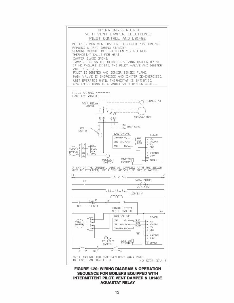
NNOOTTEE:: IIff aannyy oorriiggiinnaall wwiirree ssuupppplliieedd wwiitthh tthhee bbooiilleerrmmuusstt bbee rreeppllaacceedd,, uussee ssiimmiillaarr wwiirree ooff 110055 CC rraattiinngg..OOtthheerrwwiissee,, iinnssuullaattiioonn mmaayy mmeelltt oorr ddeeggrraaddee,, eexxppoossiinnggbbaarree wwiirree..
NNOOTTEE:: BBooiilleerr ttrraannssffoorrmmeerr mmuusstt nnoott bbee uusseedd ttoo ppoowweerreexxtteerrnnaall aacccceessssoorriieess ((ii..ee..,, zzoonnee vvaallvveess,, rreellaayyss,, eettcc..))..OOtthheerrwwiissee,, bbooiilleerr ttrraannssffoorrmmeerr wwiillll bbee oovveerrllooaaddeedd aannddwwiillll bbuurrnn oouutt..
A separate 115V (60Hz) power supply is recommendedfor the boiler. Use standard 15-amp fuse and 14-gaugewire from power supply to boiler. Follow the wiring dia-gram for your particular installation as shown in Figures1.20 through 1.28.
WWAARRNNIINNGG:: TTuurrnn ooffff eelleeccttrriicc ppoowweerr ssuuppppllyy bbeeffoorreesseerrvviicciinngg.. CCoonnttaacctt wwiitthh lliivvee eelleeccttrriicc ccoommppoonneennttss ccaannccaauussee sshhoocckk oorr ddeeaatthh..
12
FFIIGGUURREE 11..2200:: WWIIRRIINNGG DDIIAAGGRRAAMM && OOPPEERRAATTIIOONNSSEEQQUUEENNCCEE FFOORR BBOOIILLEERRSS EEQQUUIIPPPPEEDD WWIITTHH
IINNTTEERRMMIITTTTEENNTT PPIILLOOTT,, VVEENNTT DDAAMMPPEERR && LL88114488EEAAQQUUAASSTTAATT RREELLAAYY

13
FFIIGGUURREE 11..2211:: WWIIRRIINNGG DDIIAAGGRRAAMM && OOPPEERRAATTIIOONNSSEEQQUUEENNCCEE FFOORR BBOOIILLEERRSS EEQQUUIIPPPPEEDD WWIITTHHIINNTTEERRMMIITTTTEENNTT PPIILLOOTT && VVEENNTT DDAAMMPPEERR &&
HHIIGGHH LLIIMMIITT AAQQUUAASSTTAATT
FFIIGGUURREE 11::2222:: WWIIRRIINNGG DDIIAAGGRRAAMM && OOPPEERRAATTIIOONNSSEEQQUUEENNCCEE FFOORR BBOOIILLEERRSS EEQQUUIIPPPPEEDD WWIITTHH IIIIDD,,
VVEENNTT DDAAMMPPEERR && LL44008811BB DDUUAALL AAQQUUAASSTTAATT

14
FFIIGGUURREE 11..2233:: WWIIRRIINNGG DDIIAAGGRRAAMM && OOPPEERRAATTIIOONNSSEEQQUUEENNCCEE FFOORR BBOOIILLEERRSS EEQQUUIIPPPPEEDD WWIITTHH
SSTTAANNDDIINNGG PPIILLOOTT
FFIIGGUURREE 11..2244:: WWIIRRIINNGG DDIIAAGGRRAAMM && OOPPEERRAATTIIOONNSSEEQQUUEENNCCEE FFOORR BBOOIILLEERRSS EEQQUUIIPPPPEEDD WWIITTHH
SSTTAANNDDIINNGG PPIILLOOTT && LL88114488EE AAQQUUAASSTTAATT RREELLAAYY
CAUTION
THIS BOILER IS EQUIPPED WITH 24 VOLTCONTROLS. DO NOT CONNECT GAS VALVE
TO LINE VOLTAGE.
IF ANY OF THE ORIGINAL WIRE AS SUPPLIEDWITH THE BOILER MUST BE REPLACED,
IT MUST BE REPLACED WITH TYPE MTW(105¡C)WIRE OR ITS EQUIVALENT.
115VAC,60HZH N
115/24V
42-3902 Rev. 6
FIELD WIRING
FACTORY WIRING
TRANSFORMER
HI-LIMITAQUASTAT
THERMOSTAT
24VOLTGAS VALVE
BLK
TH
TR
115V AC
115V, 60HZ PRI.24V, 20VA SEC.
HI-LIMIT T’STAT
THTR
BLK
CAUTION
THIS BOILER IS EQUIPPED WITH 24 VOLTCONTROLS. DO NOT CONNECT GAS VALVE
TO LINE VOLTAGE.
42-5538 Rev. 4
115V ACL1 L2
T’STAT
115/24V
1K1 C1 C2
CIRC.MOTOR
JUMPER 1KT TV
Z W
IF ANY OF THE ORIGINAL WIRE AS SUPPLIEDWITH THE BOILER MUST BE REPLACED,
IT MUST BE REPLACED WITH TYPE MTW(105¡C)WIRE OR ITS EQUIVALENT.
FIELD WIRINGFACTORY WIRING
GAS VALVE
BLK
TH
TR
BLK
115V
CIRC.
AQUASTATRELAY
T Z TV
B1 B2
C1 C2
L1 L2
THERMOSTAT
THTR1K2 B RB2
B1

15
FFIIGGUURREE 11..2255:: WWIIRRIINNGG DDIIAAGGRRAAMM && OOPPEERRAATTIIOONNSSEEQQUUEENNCCEE FFOORR BBOOIILLEERRSS EEQQUUIIPPPPEEDD
WWIITTHH IINNTTEERRMMIITTTTEENNTT PPIILLOOTT
FFIIGGUURREE 11..2266:: WWIIRRIINNGG DDIIAAGGRRAAMM && OOPPEERRAATTIIOONNSSEEQQUUEENNCCEE FFOORR BBOOIILLEERRSS EEQQUUIIPPPPEEDD WWIITTHH
IINNTTEERRMMIITTTTEENNTT PPIILLOOTT && LL88114488EE AAQQUUAASSTTAATT RREELLAAYY
16
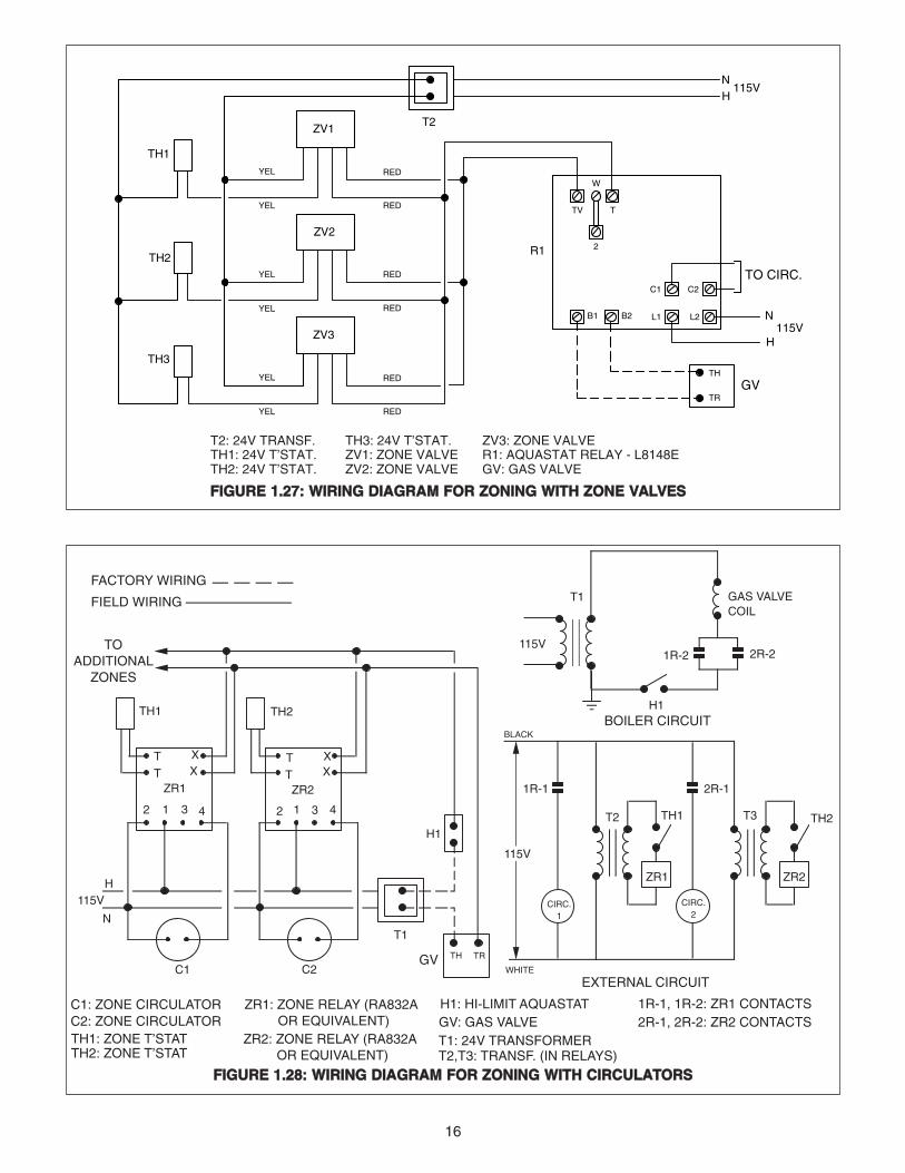
T2: 24V TRANSF.TH1: 24V T’STAT.TH2: 24V T’STAT.
TH3: 24V T’STAT.ZV1: ZONE VALVEZV2: ZONE VALVE
ZV3: ZONE VALVER1: AQUASTAT RELAY - L8148EGV: GAS VALVE
TH1
TH2
NH
115V
TH3
ZV1
ZV2
ZV3
T2
YEL RED
YEL RED
R1
TV T
2
W
B1 B2
TH
TR
C1 C2
L1 L2
GV
N
H115V
TO CIRC.RED
RED
RED
RED
YEL
YEL
YEL
YEL
FFIIGGUURREE 11..2277:: WWIIRRIINNGG DDIIAAGGRRAAMM FFOORR ZZOONNIINNGG WWIITTHH ZZOONNEE VVAALLVVEESS
C2C1
2 31 4
TT
2 31 4
XX
T
XTX
TH1 TH2
ZR1 ZR2
N
H115V
TH TRGV
T1
TO ADDITIONAL
ZONES
H1
C1: ZONE CIRCULATOR
TH1: ZONE T’STATC2: ZONE CIRCULATOR
TH2: ZONE T’STAT
ZR1: ZONE RELAY (RA832A OR EQUIVALENT)ZR2: ZONE RELAY (RA832A OR EQUIVALENT)
H1: HI-LIMIT AQUASTATGV: GAS VALVET1: 24V TRANSFORMERT2,T3: TRANSF. (IN RELAYS)
1R-1, 1R-2: ZR1 CONTACTS2R-1, 2R-2: ZR2 CONTACTS
FACTORY WIRING
FIELD WIRING T1
115V1R-2 2R-2
H1BOILER CIRCUIT
1R-1
T2
2R-1
T3 TH2TH1
ZR1 ZR2
CIRC.1
CIRC.2
115V
BLACK
WHITE
EXTERNAL CIRCUIT
GAS VALVECOIL
FFIIGGUURREE 11..2288:: WWIIRRIINNGG DDIIAAGGRRAAMM FFOORR ZZOONNIINNGG WWIITTHH CCIIRRCCUULLAATTOORRSS

17
SSEECCTTIIOONN 22:: SSTTAARRTT--UUPP && OOPPEERRAATTIIOONN
SSAAFFEETTYY CCOONNTTRROOLLSSSpill switch (seeFigure 2.1) detects theescape of combustionproducts through thedraft hood relief open-ing and interrupts thepower to the gas valvepreventing unsafe boil-er operation. Escapeof flue products couldbe caused by ablocked or collapsedchimney or by inade-quate chimney draft.TThhiiss iiss aa mmaannuuaall rree--sseett--ttyyppee ddeevviiccee aannddccaann bbee rreeaaccttiivvaatteedd bbyyddeepprreessssiinngg tthhee ssppiillllsswwiittcchh rreesseett bbuuttttoonn..
Flame rollout switch(see Figure 2.1) pre-vents flame rollout from the boiler combustion chamber,caused by blocked boiler flue passageways, by interrupt-ing power to the gas valve to prevent unsafe boiler oper-ation. TThhiiss iiss aa ssiinnggllee uussee ddeevviiccee aanndd mmuusstt bbee rree--ppllaacceedd iiff iitt iiss ttrriippppeedd.. Flue passages must be inspect-ed by a qualified installer if problem occurs, prior toswitch replacement.
SSTTAARRTT--UUPP && AADDJJUUSSTTMMEENNTTSSSafe lighting and other performance criteria were metwith the gas manifold and control assembly provided onthe boiler when the boiler underwent tests specified inANSI Z21.13-1991.
1. Bleed all heating system air vents, starting on lowest
SPILL SWITCH
ROLLOUTSWITCH
floor. Open vents one at a time until water squirts out.Close vent and repeat procedure with remaining vents.
2. Make sure boiler combination gas valve is in OFFposition. Then, open main gas shutoff valve, allowing gasto flow to boiler.
3.Set thermostat heat anticipator at .8 amp when therm-ostat is controlling boiler directly. When zone controlled,set heat anticipator to amp draw of zone valve or circu-lator pump relay.
4. Set thermostat to call for heat and turn on electricalpower to boiler.Observe that ventdamper position indi-cator has rotated toopen position (seeFigure 2.2). DDaammppeerrmmuusstt bbee iinn ooppeennppoossiittiioonn wwhheenn bbooiill--eerr mmaaiinn bbuurrnneerr iissooppeerraattiinngg.. IInn ccaasseeooff aa ddaammppeerr mmaall--ffuunnccttiioonn,, tthheeddaammppeerr bbllaaddee mmaayybbee mmaannuuaallllyy ppllaacceeddiinn tthhee ffuullll ooppeennppoossiittiioonn ttoo ppeerrmmiitt bbuurrnneerr ooppeerraattiioonn.. TToo aaccccoommpplliisshhtthhiiss,, ffiirrsstt ddiissccoonnnneecctt eelleeccttrriiccaall ppoowweerr aanndd tthheenn sseeppaa--rraattee tthhee vveenntt ccoonnnneeccttoorr ffrroomm tthhee ddaammppeerr.. MMaannuuaallllyy((uussiinngg hhaanndd ttoooollss iiff rreeqquuiirreedd)) rroottaattee tthhee bbllaaddee uunnttiilltthhee eenndd sswwiittcchh cclloosseess.. RReeppoossiittiioonn aanndd rreeccoonnnneecctt tthheevveenntt ccoonnnneeccttoorr ttoo tthhee bbooiilleerr bbeeffoorree ttuurrnniinngg oonn tthheeeelleeccttrriiccaall ppoowweerr..
5. Allow circulator to run 15 to 30 minutes, which shouldpurge any leftover air from system. Check automatic airvent for the proper operation and entire system for anyleaks. Make sure all air is purged from system beforelighting boiler.
6. Set thermostat to no longer call for heat. Observe thatdamper position indicator rotated to closed position.
7. Set thermostat to lowest setting and light boiler follow-ing lighting instructions in Figures 2.4, 2.5, 2.6 & 2.7.Boiler is equipped with flame rollout switch to shut downboiler in case of sustained flame roll-out or excessiveheat behind front panel. If switch opens, see the infor-mation on “Safety Controls” on this page.
8. Observe pilot and main burner flame (see Figure 2.3).All burner ports should be ignited and burn with a steadyblue flame.
DAMPER POSITION INDICATORMUST BE IN VISIBLE LOCATIONFOLLOWING INSTALLATION.
OPENCLOSED
FLOW DIRECTION
FIGURE 2.2
FIGURE 2.1
DDAANNGGEERR:: IIff ffllaammee rroolllloouutt sswwiittcchh oorr ssppiillll sswwiittcchh ttrriippssrreeppeeaatteeddllyy dduurriinngg ssttaarrtt--uupp oorr ooppeerraattiioonn,, iitt iinnddiiccaatteess aahhaazzaarrddoouuss ccoonnddiittiioonn ttoo bbee ccoorrrreecctteedd iimmmmeeddiiaatteellyy..
WWAARRNNIINNGG:: IIff bbooiilleerr ccaannnnoott bbee rreessttoorreedd ttoo nnoorrmmaallooppeerraattiioonn aafftteerr rreesseettttiinngg ooff ssppiillll sswwiittcchh,, oorr iiff ffllaammeerroolllloouutt sswwiittcchh hhaass ttrriippppeedd,, ddoo nnoott aatttteemmpptt ttoo ppuutt tthheebbooiilleerr iinn ooppeerraattiioonn.. IImmmmeeddiiaatteellyy ccoonnttaacctt aa qquuaalliiffiieeddsseerrvviiccee pprrooffeessssiioonnaall..
WWAARRNNIINNGG:: KKeeeepp bbooiilleerr aarreeaa cclleeaarr aanndd ffrreeee ffrroomm ccoomm--bbuussttiibbllee mmaatteerriiaallss,, ggaassoolliinnee aanndd ootthheerr ffllaammmmaabblleevvaappoorrss aanndd lliiqquuiiddss.. OOtthheerrwwiissee,, ffiirree oorr eexxpplloossiioonn mmaayyrreessuulltt..

18
CCAAUUTTIIOONN:: NNeevveerr lleeaavvee tthhee jjoobb wwiitthh yyeellllooww bbuurrnniinnggffllaammeess.. TThhiiss ccoonnddiittiioonn iinnddiiccaatteess ppoooorr ccoommbbuussttiioonnaanndd wwiillll qquuiicckkllyy ccaarrbboonniizzee tthhee bbooiilleerr,, rreedduucciinngg eeffffii--cciieennccyy aanndd bbooiilleerr lliiffee.. IItt mmaayy aallssoo bbee aann iinnddiiccaattiioonn ooffiimmpprrooppeerr vveennttiinngg oorr ccoommbbuussttiioonn aaiirr ssuuppppllyy.. IIff uunnaabblleettoo aaddjjuusstt ffllaammee pprrooppeerrllyy,, ccoonnssuulltt yyoouurr llooccaall uuttiilliittyy..
9. Boilers are shipped from the factory with the primaryair shutters on the main burner wide open. It is recom-mended these air shutters be left in the wide open posi-tion unless there is lifting of the flame above the burnerports. If there is lifting, the air shutters should be gradu-ally closed until the lifting is eliminated. It may also benecessary to adjust the primary air shutters if the inputrate is reduced by a change in the orifices.
10. After burner has been in operation for about 10 min-utes, check gas input rate to boiler as follows:
a. Make sure that all appliances served by meter areturned off during timing of gas input rate to the boiler.
b. Measure the time in seconds it takes for the boilerto use10 cubic feet of gas. Divide 36,000 by the num-ber of seconds (this is the number of cubic feet of gas
used per hour). Multiply this figure by the heatingvalue of the gas to obtain Btu input per hour.
Example: An R-300B boiler takes 2 minutes to use 10cubic feet of natural gas. Local utility indicated heatingvalue of the natural gas being supplied is 1020 Btu/cuft. Therefore:
(2x60) = 120 seconds
36,000 x 1020 = 306,000 Btu/hr120
Therefore, the boiler input is correct.
NNOOTTEE:: BBeeffoorree ccaallccuullaattiinngg tthhee iinnppuutt ooff tthhee hheeaattiinnggeeqquuiippmmeenntt,, oobbttaaiinn tthhee hheeaattiinngg vvaalluuee ooff tthhee ggaass ffrroommtthhee llooccaall uuttiilliittyy..
11. If boiler input needs to be corrected, adjust the com-bination gas valve pressure regulator. (Regulator is fac-tory set at 3.5” W.C. for natural gas or 10” W.C. forpropane.) Turn adjusting screw clockwise to increase gasflow (increase input). Turn adjusting screw counterclock-wise to decrease gas flow (decrease input). In no case,should final manifold pressure setting vary more than .2”from factory-set pressures. If rated input cannot beobtained with regulator adjustment, gas supply pressureor orifice size may be the cause. Consult your local utili-ty and Hydrotherm.
12. The gas burner orifices supplied with the boiler havebeen carefully designed to provide the correct gas inputrate for most gas conditions typically found in the U.S.Occasionally, however, the local gas characteristics maynot allow the unit to be properly adjusted for input. If thisis the case, the local utility or Hydrotherm may recom-mend the orifices be changed. When changing orifices,follow the procedures in Section 3 of this manual.
13. Start and stop burners several times by raising andlowering the thermostat setting.
14. After the boiler has been firing long enough to raisethe boiler water temperature to above the minimum set-ting of the high limit, check the high limit by turning its set-ting from maximum to minimum setting. This should turnthe boiler off. Return high limit to desired setting.
15. With the boiler firing, disconnect the wire connectedto the “PV” terminal on Honeywell S8600 control. Gasvalve should close.
NORMAL PILOT FLAME
Q314ALBSTANDING
PILOTMODELS
LIFTING(TOO MUCH AIR)
YELLOWTIPPING
(MARGINAL)
MAIN BURNER FLAMES
NORMAL(HARD FLAME)
YELLOWFLAME
(TOO LITTLE AIR)
Q345ALBINTERMITTENT
IGNITIONPILOT
MODELS
Q314ALBSTANDING PILOT
MODELS
FIGURE 2.3

19
1. SSTTOOPP!! Read the safety information above.2. Set the thermostat to lowest setting.3 Turn off all electric power to the appliance.4. This appliance is equipped with an ignition devicewhich automatically lights the pilot. Do not try to light thepilot by hand.5 Remove control access panel, (if applicable)6. Rotate gas control knob clockwise to “OFF”7. Wait five (5) minutes to clear out any gas.Then smell for gas, including near the floor.If you then smell gas SSTTOOPP!! Follow “A” in the safety infor-mation above. If you don’t smell gas, go to next step.8. Turn gas control knob counterclockwise to “ON”.9. Replace control access panel.
10. Turn on all electric power to the appliance.11. Set the thermostat to the desired setting.12. If the appliance will not operate, follow the instructions“To Turn Off Appliance” and call your service technician orgas supplier.
WWAARRNNIINNGG::IIff yyoouu ddoo nnoott ffoollllooww tthheessee iinnssttrruuccttiioonnss eexxaaccttllyy,, aa ffiirree oorr eexxpplloossiioonn mmaayy rreessuulltt wwiitthh pprrooppeerrttyy ddaammaaggee,, ppeerrssoonnaall iinnjjuurryy,, oorr lloossss ooff lliiffee..
AA.. BBEEFFOORREE OOPPEERRAATTIINNGG smell all around the appliancearea for gas. Be sure to smell next to the floor becausesome gas is heavier than air and will settle on the floor.
WWHHAATT TTOO DDOO IIFF YYOOUU SSMMEELLLL GGAASS• Do not try to light any appliance.• Do not touch any electrical switch; do not use any phone
in your building.Follow the gas supplier’s instructions.• If you cannot reach your gas supplier, call the fire
department.
BB.. Use only your hand to push in or turn the gas controlknob, don’t try to repair it, call a qualified service tech-nician. Force or attempted repair may result in a fire orexplosion.
CC.. Do not use this appliance if any part has been underwater. Immediately call a qualified service technician toinspect the appliance and to replace any part of thecontrol system and any gas control which has beenunder water.
LLIIGGHHTTIINNGG CCOONNTTIINNUUOOUUSS PPIILLOOTT IINNSSTTRRUUCCTTIIOONNSSSSttaannddiinngg PPiilloott HHoonneeyywweellll VVRR88330000
NNaattuurraall oorr PPrrooppaannee GGaass
TThhiiss aapppplliiaannccee hhaass aa ppiilloott wwhhiicchh mmuusstt bbee lliitt bbyy hhaanndd.. WWhheenn lliigghhttiinngg tthhee ppiilloott,, ffoollllooww tthheessee iinnssttrruuccttiioonnss eexxaacctt--
11.. SSTTOOPP!! Read the safety information above on thispage.2. Set the thermostat to lowest setting.3. Turn off all electric power to the appliance.4. Remove control access panel (If applicable).5. Turn gas control knob clockwise to “OFF”.6. Wait five (5) minutes to clear out any gas. Then smellfor gas, including near the floor. If you then smell gas,SSTTOOPP!! Follow “A” in the safety information above. If youdon’t smell gas, go to the next step.7. Remove the base door covering the top of the burnersand enclosing the pilot.8. Find pilot – Follow metal tube from gas control. Thepilot is between the central burner tubes behind the basedoor.9. Turn knob on gas control counterclockwise to “Pilot”.10. Push down and hold the red button next to the controlknob. Immediately light the pilot with a match.Continue to hold the red button down for about one (1)minute after the pilot is lit. Release button and it will pop back up. Pilot shouldremain lit. If it goes out, repeat steps 5 through 10.
• If button does not pop up when released, stop immedi-ately and call your service technician or gas supplier.• If the pilot will not stay lit after several tries, turn the gascontrol knob to “OFF” and call your service technician orgas supplier.11. Replace the base door.12. Turn gas control knob counterclockwise to “ON”.13. Turn on all electric power to the appliance.14. Set thermostat to desired setting.
INLET
GAS CONTROL KNOB SHOWN IN "OFF" POSITION
GAS ON
OFF
RESET BUTTON
PILOT
OOPPEERRAATTIINNGG IINNSSTTRRUUCCTTIIOONNSSHHoonneeyywweellll VVRR88330044
HHoonneeyywweellll VVRR88330000
INLET
GAS CONTROL KNOB SHOWN IN "OFF" POSITION
GAS ON
OFF

20
SSEECCTTIIOONN 33:: MMAAIINNTTEENNAANNCCEEThis boiler has been designed to provide years of troublefree performance in normal installations. Examination bythe homeowner at the beginning of each heating season,and in mid-heating season, should assure continuedgood performance. In addition, the boiler should beexamined by a qualified service professional at leastonce every year.
NNOOTTEE:: BBooiilleerr iiss nnoott ffoorr uussee iinn ssyysstteemmss wwhheerree wwaatteerriiss rreepplleenniisshheedd.. DDoo nnoott ddrraaww wwaatteerr ffrroomm ssyysstteemm ffoorrcclleeaanniinngg.. MMiinneerraallss iinn wwaatteerr ccaann bbuuiilldd uupp oonn hheeaattttrraannssffeerr ssuurrffaacceess aanndd ccaauussee oovveerrhheeaattiinngg aanndd ssuubbssee--qquueenntt ffaaiilluurree ooff ccaasstt iirroonn sseeccttiioonnss..
NNOOTTEE:: DDoo nnoott oobbssttrruucctt tthhee ffllooww ooff ccoommbbuussttiioonn aannddvveennttiillaattiioonn aaiirr..
NNOOTTEE:: IIff bbooiilleerr iiss eeqquuiippppeedd wwiitthh aa llooww wwaatteerr ccuuttooffff,,ffoollllooww mmaannuuffaaccttuurreerr’’ss mmaaiinntteennaannccee iinnssttrruuccttiioonnss..
WWAATTEERR TTRREEAATTMMEENNTTWater treatment is recommended in areas where waterquality is a problem. A local water treatment companyshould be consulted to determine the requirements foryour particular system and locality.
FFRREEEEZZEE PPRROOTTEECCTTIIOONNWhere absolutely necessary, system antifreeze can beutilized. It must be compatible with hydronic heating sys-tems. System must be designed to accommodate nec-essary changes in heat transfer, pump head, flow rate &expansion. For more information, consult The HydronicsInstitute Technical Topics Number 2A publication.
NNOOTTEE:: NNeevveerr uussee aann RRVV--ttyyppee aannttiiffrreeeezzee pprrootteeccttiioonnssoolluuttiioonn nnoorr aann aauuttoommoottiivvee--ttyyppee aannttiiffrreeeezzee aass ddaamm--aaggee ttoo tthhee bbooiilleerr aanndd ootthheerr ssyysstteemm ccoommppoonneennttss mmaayyrreessuulltt..
BBEEFFOORREE EEAACCHH HHEEAATTIINNGG SSEEAASSOONN1. Remove and inspect draft hood and vent piping (con-necting draft hood to chimney or vent) for obstructions,soot accumulation, rust or corrosion. Clean and replaceas necessary. Check tightness of joints; seal all jointswhere necessary.
2. Check boiler flue passageways in the boiler sectionsfor any blockage or soot accumulation. Remove drafthood, jacket top and cast iron dome. Using a flash light,examine all flue passageways.
a. If passageways are free of soot and obstructions,replace dome and seal with furnace cement or hightemperature silicone adhesive/sealant.
b. If passageways need cleaning, remove burners asdescribed in paragraph 3 below. Insert long-handlebristle flue brush down between section tubes andupward through sections from combustion chamber inboth diagonal directions to remove carbon from fin-ned surfaces. Vacuum debris. Replace dome and sealwith furnace cement or high temperature siliconeadhesive/sealant.
c. Reinstall jacket top panel and draft hood.
3. Check and clean burner assembly. Remove burneraccess panel. To remove burners, lift up and to rear untilburners are disengaged from orifices. Brush top of burn-ers with soft bristle brush; blow out with air or vacuum.
4. Check gas manifold for proper position and reassem-ble burners to the manifold. Line up holes in burners withthe orifices and slide assembly back into position. BESURE TO REINSTALL BURNER WITH PORTS ON THETOP SURFACE (UPRIGHT).
5. When a low water cut-off has been utilized, follow themanufacturer’s maintenance instructions. As a minimum,test electronic control operation at least once a year.Float type controls should be flushed twice a year.
6. Lubricate circulator motor according to manufacturer’sinstructions. This information may be contained in label-ing on the pump frame.
7. Follow “System Start-Up & Adjustments” procedures inSection 2 of this manual.
DDAANNGGEERR:: TToo aavvooiidd ffiirree aanndd eexxpplloossiioonn hhaazzaarrddss:: DDoonnoott ssttoorree aannyytthhiinngg aaggaaiinnsstt bbooiilleerr oorr aallllooww ddiirrtt//ddeebbrriissttoo aaccccuummuullaattee iinn aarreeaa iimmmmeeddiiaatteellyy ssuurrrroouunnddiinngg bbooiill--eerr.. KKeeeepp bbooiilleerr aarreeaa cclleeaarr aanndd ffrreeee ffrroomm ccoommbbuussttiibblleemmaatteerriiaallss,, ggaassoolliinnee aanndd ootthheerr ffllaammmmaabbllee vvaappoorrss aannddlliiqquuiiddss.. DDoo nnoott aallllooww lliinntt,, ppaappeerr oorr rraaggss ttoo aaccccuummuu--llaattee nneeaarr bbuurrnneerrss.. DDoo nnoott ppllaaccee ccllootthhiinngg oonn bbooiilleerr ttooddrryy..
TTOO TTUURRNN OOFFFF GGAASS TTOO AAPPPPLLIIAANNCCEE1. Set the thermostat to lowest setting.2. Turn off all electric power to the appliance if service is
to be performed.
3. Turn gas control knob counterclockwise to “OFF” Donot force.

21
HHOOWW TTOO CCHHAANNGGEE OORRIIFFIICCEESS1. Shut off power supply and gas supply to the boiler.
2. Remove burner access panel. To remove burners, liftup & to rear until burners are disengaged from orifices.
3. Check orifices for proper drill size. Size is stampedonto the body of the brass orifice. The size can also bechecked by using a pin gauge (see Figure 3.1). All ori-fices are screwed into the manifold and may be removedby using a 5/8” wrench or socket.
4. Reverse above procedures to install orifices & burn-ers. BE SURE TO INSTALL BURNERS WITH BURNERPORTS ON TOP SURFACE (UPRIGHT).
DRILL SIZEMODEL
MANIFOLDPRESSURE
N.G. L.P.
NAT. GAS1000 BTU
CU. FT .60 SG.
L.P. GAS2500 BTU
CU. FT 1.5 SG
TYPE OF GAS
R-180CR-210CR-250CR-300B
3.53.53.53.5
10.010.010.010.0
52515149
39353531
FIGURE 3.1
NNOO HHEEAATT1. Blown fuse or circuit breaker.2. Power switch turned off.3. IID system malfunction.4. Vent damper not open.5. Circulator not running.6. Air in lines and radiation.7. Tripped rollout switch.8. Tripped spill switch.
IINNSSUUFFFFIICCIIEENNTT HHEEAATT1. Incorrect t’stat anticipator setting.2. Hi-limit control setting too low.3. Boiler undersized or underfired.4. Insufficient radiation.
5. Air traps in lines or radiation.
OOVVEERRHHEEAATTIINNGG1. Wrong thermostat anticipator set-
ting.2. Bad thermostat location.3. Bad thermostat.
OODDOORR,, EEXXCCEESSSSIIVVEE MMOOIISSTTUURREE IINNBBUUIILLDDIINNGG1. Leak in piping.2. Carbon build-up in flueways.3. Blocked chimney.4. Downdrafts- incorrect termination
YYEELLLLOOWW FFLLAAMMEE,, CCAARRBBOONNBBUUIILLDD--UUPP1. Unit overfired.2. Air shutter misadjustment3. Wrong orifices.4. Burning in burner mixing tube.5. Inadequate combustion air.6. Inadequate draft (flue blockage).
NNOOIISSEE1. Ignition-incorrect air shutter
adjustment.2. Whistle due to burr on orifices.3. Burner “fluteing” -air shutter open-ing too wide.
TTRROOUUBBLLEESSHHOOOOTTIINNGG
CCAAUUTTIIOONN::LLaabbeell aallll wwiirreess pprriioorr ttoo ddiissccoonnnneeccttiioonn wwhheenn sseerrvviicciinngg ccoonnttrroollss.. WWiirriinngg eerrrroorrss ccaann ccaauussee iimmpprrooppeerr aanndd ddaannggeerr--oouuss ooppeerraattiioonn.. VVeerriiffyy pprrooppeerr ooppeerraattiioonn aafftteerr sseerrvviicciinngg..
OOrriiffiiccee SSiizzeeMMooddeell ## FFuueell TTyyppee OOrriiffiiccee QQttyy.. SSeeaa LLeevveell 22000000 fftt.. 33000000 fftt.. 44000000 fftt.. 55000000 fftt.. 66000000 fftt.. 77000000 fftt.. 88000000 fftt.. 99000000 fftt.. 1100000000 fftt..
R-180C NG 6 39 40 41 41 42 42 43 43 44 44
R-180C LP 6 52 52 53 53 53 53 53 54 54 54
R-210C NG 6 35 36 36 37 37 38 39 40 41 42
R-210C LP 6 51 51 52 52 52 52 53 53 53 54
R-250C NG 7 35 36 36 37 37 38 39 40 41 42
R-250C LP 7 51 51 52 52 52 52 53 53 53 54
R-300B NG 7 31 32 32 32 33 34 35 36 37 38
R-300B LP 7 49 50 50 50 51 51 51 52 52 52
EEQQUUIIVVAALLEENNTT OORRIIFFIICCEE SSIIZZEESS AATT HHIIGGHH AALLTTIITTUUDDEESS ((IINNCCLLUUDDEESS 44%% IINNPPUUTT RREEDDUUCCTTIIOONN FFOORR EEAACCHH 11,,000000 FFEEEETT
OORRIIFFIICCEE HHYYDDRROOTTHHEERRMMSSIIZZEE PPAARRTT NNOO..31 25-111832 25-113233 25-113034 25-111935 25-112636 25-112037 25-1121
OORRIIFFIICCEE HHYYDDRROOTTHHEERRMMSSIIZZEE PPAARRTT NNOO..38 25-113739 25-112540 25-113641 25-113542 25-111143 25-111244 25-1113
OORRIIFFIICCEE HHYYDDRROOTTHHEERRMMSSIIZZEE PPAARRTT NNOO..49 25-112750 25-112351 25-112452 25-112953 25-112854 25-1115
OORRIIFFIICCEE PPAARRTT NNUUMMBBEERRSS

22
APPENDIX A
1. Monter le volet de ventilation sur la partie supérieure du coupe-tirage.
MONTER LE VOLETDE VENTILATIONAU-DESSUS DU COUPE-TIRAGE.
LA FLÈCHE DE DIRECTIONDE L'ÉCOULEMENT POINTEVERS LE HAUT
FIGURE 1.9
MÉTHODE D' INSTALLATION B: pour le volet motorisé de ventilation.
DANGER: Le volet de ventilation doit servir seulement á la chaudière. Ne pas l'utiliserpour ventiler d'autres appareils; sinon cela pourrait provoquer un incendie ou causer un
empoisonnement par le monoxyde de carbone.
2. Fixer le volet de ventilation au coupe-tirage.
FIGURE 1.10
ATTACHER LA PARTIEINFÉRIEURE DU VOLETDE VENTILATION AUCOUPE-TIRAGE À L'AIDEDE VIS DE 1/2 po OU PLUSCOURTES OU DES RIVETSAVEUGLES.
FIGURE 1.12
3. Verifier le fonctionnement du volet de ventilation.'
FAISCEAU DE FILSDU VOLET DEVENTILATION.
FIGURE 1.11
OUVERT
OUVERT
1
2
4. Brancher le faisceau de fils.
S'ASSURER QUELE VOLET DEVENTILATIONTOURNE VERSLA POSITIONOUVERTESANSOBSTRUCTION.
ENLEVER L ATTACHED'EXPÉDITION.
ENFICHER DANS LA PRISEMOLEX SUR LE DEVANTDE LA CHAUDIÈRE.
ENFICHER DANS LA PRISEMOLEX À L'INTÉRIEUR DUMOTEUR DU VOLET DEVENTILATION.
S'ASSURE QUELE MOTEUR SOITSITUÉ A GAUCHE
LE REGISTRE DOIT ETRE ENPOSITION OUVERTE LORSQUELE BRULEUR PRINCIPAL EST ENMARCHE.
OUVERTECLOS
SENS DE DEBIT
^
^
FIGURE 2.2

23
MMOODDEELL RR SSEERRIIEESS
RREEPPLLAACCEEMMEENNTTPPAARRTTSS LLIISSTT
ORDERING INFORMATIONWhen ordering replacement parts, providethe model and serial number shown on theunit rating plate as well as the part numberand name as shown in the parts list. Partsmay be obtained from your local Hydro-therm heating contractor.
RREEFF NNUUMMBBEERR RREEQQUUIIRREEDD PPEERR BBOOIILLEERR NNOO.. NNAAMMEE OOFF PPAARRTT PPAARRTT NNOO.. RR--118800CC RR--221100CC RR--225500CC RR--330000BB
1 Absorption Unit BM-3105 1 1Absorption Unit BM-3106 1 1
2 Section, Base BM-9686 1 1 1 13 Section, Middle BM-9689 2 2 3 3
Section, Middle (1/2" Tap) BM-9690 1 1 1 14 Section, Top BM-9691 1 1
Section, Top BM-9692 1 15 Push Nipple 53-1373 4 4 5 56 Tie Rod - 5/16X16 1/2" with N. & W. 44-1116 2 2
Tie Rod - 5/16X20" with N.& W. 44-1105 2 2
7 Base Side Plate - L.H. - Insulated BM-3333 1 1 1 18 Base Side Plate - R.H. - Insulated BM-3334 1 1 1 19 Front Tie Bar 03-3024 1 1 1 1
10 Rear Tie Plate - Insulated BM-3335 1 1 1 111 Base Door - Insulated BM-3336 1 1 1 112 Bracket, Manifold - L.H. 55-1606 1 1 1 113 Bracket, Manifold - R.H. 55-1607 1 1 1 114 Bracket, Burner 55-1030 1 1
Bracket, Burner 55-1031 1 115 Reflector Shield 03-3219 1 1 1 116 Burner (Nat.) 03-7112 5 5 6 6
Burner (Prop.) 03-7114 5 5 6 6Burner w/Pilot Bracket (Nat.) 03-7117 1 1 1 1Burner w/Pilot Bracket (Prop.) 03-7118 1 1 1 1

24
17 Burner Orifice#39 (Nat.) (R Only) 25-1125 6Burner Orifice #35 (Nat.) R Only 25-1126 6 7Burner Orifice #31 (Nat.) 25-1118 7Burner Orifice # 52 (Prop.) 25-1129 6Burner Orifice # 51 (Prop.) 25-1124 6 7Burner Orifice # 49 (Prop.) 25-1127 7
18 Manifold 24-1109 1 1Manifold 24-1110 1 1
19 Pilot Ass'y-Nat.Q314A w/Q309A&BCR18 BM-8072 1 1 1 1Pilot Ass'y-Prop.Q314A w/Q309A&BBR10 BM-8073 1 1 1 1
20 Pilot Orifice - Nat. (BCR18) 62-3326 1 1 1 1Pilot Orifice - Prop. (BBR10) 62-3327 1 1 1 1
22 Thermocouple - (Q309A) 04-1302 1 1 1 123 Pilot Line with Fittings BM-3318 1 1 1 124 Gas Valve - Nat. VR8300C 4043 02-1552 1 1 1 1
Gas Valve - Prop. VR8300C 4035 02-1553 1 1 1 125 Hi-Limit Aquastat-L4006A BM-4897 1
Hi-Limit Aquastat-L4080B 02-2700 1 1 1Aquastat Relay-R8148E 02-2406 1 1 1 1
26 Well - 1/2" 02-3413 1 1 1 127 Temp./Press. Indicator (For 30 # R.V.) 20-1014 1 1 1 1
Temp./Press. Indicator (For 50 # R.V.) 20-1003 1 1 1 1Temp./Press. Indicator (For 75/100 # R.V.) 20-1011 1 1 1 1
29 Grid Ass'y. BM-9614 1Grid Ass'y. BM-9615 1Grid Ass'y. BM-9616 1Grid 03-2206.1 1
30 Dome - 7" 01-2104 1 1Dome - 7" 01-2106 1Dome - 8" 01-2105 1
31 Bracket, Dome 55-3800 2 2 2 232 Draft Hood for Spill Switch - 7" (R Only) 03-8144 1
Draft Hood for Spill Switch- 7"(R Only) 03-8143 1 1Draft Hood - 8" (R-300) 03-7609 1
33 Nipple - 3/4" X 9 " 53-1133 1 1Nipple - 3/4" X 11" 53-1135 1 1
34 Coupling - 3/4" 56-5001 1 1 1 135 Press. Relief Valve - 30 PSI 22-1203 1 1 1 1
Press. Relief Valve - 50 PSI 22-1200 1 1 1 1Press. Relief Valve - 75 PSI 22-1803 1 1 1 1Press. Relief Valve - 100 PSI 22-1201 1 1 1 1
36 Transformer - 115/24V, 20VA 26-3005 1 1 1 137 Junction Box - 24V 58-1800 1 1 1 138 Side Panel - Jacket 03-1060.1 2 2 2 239 Front Panel - Jacket 03-1033 1 1 1 140 Rear Panel - Jacket 03-1034 1 1 1 141 Top Panel - L.H. - Jacket 03-1060.4 1 1 1 142 Top Panel - R.H. - Jacket 03-1060.6 1 1 1 1- Jacket Ass'y (Less Front Panel) 03-1032 1 1 1 1- Cope Seal - 5 Ft. Increments 10-6625 - - - -
RREEFF NNUUMMBBEERR RREEQQUUIIRREEDD PPEERR BBOOIILLEERR NNOO.. NNAAMMEE OOFF PPAARRTT PPAARRTT NNOO.. RR--118800CC RR--221100CC RR--225500CC RR--330000BB

25
41 42
38
44
39
48*
20 & 50*
* THESE ITEMS ARE USED WITHINTERMITTENT PILOT SYSTEMS
36 & 46*
37
25
26
27
35
34
33
6
57
12
11
9
24 & 47*
23
18
19 & 20
17
22
16
13
8
14
15
10
4
3
3
2
1
29
30
31
32
43
38
40
FFIIGGUURREE 11:: RR GGEENNEERRAALL AASSSSEEMMBBLLYY
26
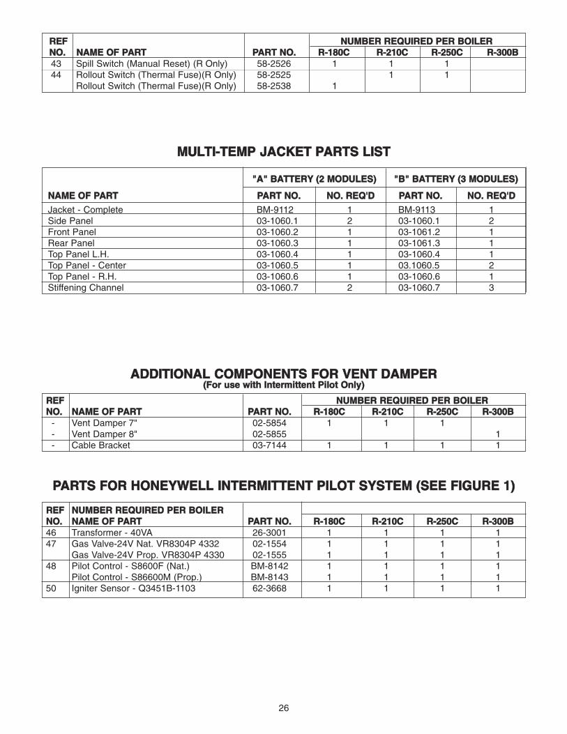
RREEFF NNUUMMBBEERR RREEQQUUIIRREEDD PPEERR BBOOIILLEERR NNOO.. NNAAMMEE OOFF PPAARRTT PPAARRTT NNOO.. RR--118800CC RR--221100CC RR--225500CC RR--330000BB43 Spill Switch (Manual Reset) (R Only) 58-2526 1 1 144 Rollout Switch (Thermal Fuse)(R Only) 58-2525 1 1
Rollout Switch (Thermal Fuse)(R Only) 58-2538 1
MMUULLTTII--TTEEMMPP JJAACCKKEETT PPAARRTTSS LLIISSTT
""AA"" BBAATTTTEERRYY ((22 MMOODDUULLEESS)) ""BB"" BBAATTTTEERRYY ((33 MMOODDUULLEESS))
NNAAMMEE OOFF PPAARRTT PPAARRTT NNOO.. NNOO.. RREEQQ''DD PPAARRTT NNOO.. NNOO.. RREEQQ''DD
Jacket - Complete BM-9112 1 BM-9113 1Side Panel 03-1060.1 2 03-1060.1 2Front Panel 03-1060.2 1 03-1061.2 1Rear Panel 03-1060.3 1 03-1061.3 1Top Panel L.H. 03-1060.4 1 03-1060.4 1Top Panel - Center 03-1060.5 1 03.1060.5 2Top Panel - R.H. 03-1060.6 1 03-1060.6 1Stiffening Channel 03-1060.7 2 03-1060.7 3
AADDDDIITTIIOONNAALL CCOOMMPPOONNEENNTTSS FFOORR VVEENNTT DDAAMMPPEERR((FFoorr uussee wwiitthh IInntteerrmmiitttteenntt PPiilloott OOnnllyy))
RREEFF NNUUMMBBEERR RREEQQUUIIRREEDD PPEERR BBOOIILLEERR NNOO.. NNAAMMEE OOFF PPAARRTT PPAARRTT NNOO.. RR--118800CC RR--221100CC RR--225500CC RR--330000BB
- Vent Damper 7" 02-5854 1 1 1- Vent Damper 8" 02-5855 1- Cable Bracket 03-7144 1 1 1 1
PPAARRTTSS FFOORR HHOONNEEYYWWEELLLL IINNTTEERRMMIITTTTEENNTT PPIILLOOTT SSYYSSTTEEMM ((SSEEEE FFIIGGUURREE 11))
RREEFF NNUUMMBBEERR RREEQQUUIIRREEDD PPEERR BBOOIILLEERR NNOO.. NNAAMMEE OOFF PPAARRTT PPAARRTT NNOO.. RR--118800CC RR--221100CC RR--225500CC RR--330000BB46 Transformer - 40VA 26-3001 1 1 1 147 Gas Valve-24V Nat. VR8304P 4332 02-1554 1 1 1 1
Gas Valve-24V Prop. VR8304P 4330 02-1555 1 1 1 148 Pilot Control - S8600F (Nat.) BM-8142 1 1 1 1
Pilot Control - S86600M (Prop.) BM-8143 1 1 1 150 Igniter Sensor - Q3451B-1103 62-3668 1 1 1 1

27
NNOOTTEESS

260 NORTH ELM STREETWESTFIELD, MA 01085(413) 564-5515 FAX: (413) 568-9613
5211 CREEKBANK ROADMISSISSAUGA, ONTARIO L4W 1R3(905) 625-2991 FAX: (905) 625-6610