modelling, simulation and optimal tuning of sssc-based controller
TRANSCRIPT
ISSN 1 746-7233, England, UKWorld Journal of Modelling and Simulation
Vol. 6 (2010) No. 2, pp. 110-121
Modelling, simulation and optimal tuning of SSSC-based controller in amulti-machine power system
Sidhartha Panda∗
Department of Electrical and Electronics Engineering, National Institute Of Science and Technology, Brahmapur761008, India
(Received February 13 2009, Revised July 4 2009, Accepted December 11 2009)
Abstract. A systematic procedure for modeling, simulation and optimally tuning the parameters of a StaticSynchronous Series Compensator (SSSC) controller in a multi-machine system, for power system stabilityenhancement is presented in this paper. For the simulation purpose, the model of multi-machine power sys-tem with SSSC controller is developed in MATLAB/SIMULINK using Sim Power System (SPS) blockset.The design problem of SSSC controller is formulated as an optimization problem and Real Coded GeneticAlgorithm (RCGA) is employed to search for the optimal SSSC controller parameters. By minimizing a time-domain based objective function, in which the modal oscillations of the power system are involved; stabilityperformance of the power system is improved. The results obtained from simulations validate the effective-ness of proposed modeling and tuning approach for power system stability improvement. The simulationresults also show that the proposed SSSC controller is effective in damping a range of small disturbanceconditions in the power system.
Keywords: static synchronous series compensator, modelling and simulation, optimal tuning, real codedgenetic algorithm, power system stability
1 Introduction
Recent development of power electronics introduces the use of Flexible AC transmission Systems(FACTS) controllers in power systems. FACTS controllers are capable of controlling the network conditionin a very fast manner and this unique feature of FACTS can be exploited to improve the stability of a powersystem[18]. The detailed explanations about the FACTS controllers are well documented in the literature andcan be found in [7, 12, 19]. Static synchronous series compensator (SSSC) is one of the important mem-bers of FACTS family which can be installed in series in the transmission lines. SSSC is very effective incontrolling power flow in a transmission line with the capability to change its reactance characteristic fromcapacitive to inductive[6]. An auxiliary stabilizing signal can also be superimposed on the power flow con-trol function of the SSSC so as to improve power system stability[20]. Mihalic and Papic[14] presented thebasic differences between impedance based controllable series compensation and a power electronic convert-ers with GTO thyristors based SSSC. For the time-domain simulation, the authors used a decoupled controlstructure with a predictive control loop based on the transformation of the three-phase system to the rotatingreference frame. The design, modeling and control design of a 48-step inverter based SSSC suitable for sub-synchronous resonance (SSR) analysis was presented by Kumar and Ghosh[10]. The equivalent circuit modelof the SSSC was derived from a magnetic circuit containing 18 single-phase three winding transformers andsix single-phase two winding transformers to add the output voltages of eight 3-phase inverters. Menniti etal.[13] proposed the use of SSSC to damp the transient frequency deviation in a deregulated electric powersystem. The authors proposed a method based on the application of the overlapping decomposition technique,∗ Corresponding author. E-mail address: panda [email protected].
Published by World Academic Press, World Academic Union

World Journal of Modelling and Simulation, Vol. 6 (2010) No. 2, pp. 110-121 111
to design a decentralised control law of a SSSC device where a multi-area power system is decomposed intotwo decoupled subsystems. Ngamroo et al.[16] developed a robust decentralised frequency stabilisers designof SSSC by taking system uncertainties into consideration and proposed to use a SSSC in an interconnectedpower system which was subjected to load disturbances with changing frequency in the vicinity of the inter-area oscillation mode. Jowder and Ooi[9] showed that addition of dielectric capacitors lowers the cost of seriescompensation by SSSC and reported based on HYPERSIM simulation that for an overall degree of capacitivecompensation of 0.7 pu, the SSSC component is only about 1/3 of the capacitive MVAR and at the same timethe transmissibility of the line is increased by a factor of 2.23 based on the transient stability limit. Jowder[8]
investigated the influence of the constant reactance and the constant quadrature voltage modes on the opera-tion of a radial power system and showed that the constant reactance mode provides higher damping power,synchronizing power, and transient stability limit. Castro et al.[4] investigated the impacts of three differentSSSC control modes on small-signal and transient stability of a power system, where the stability analysisand the design of the SSSC controllers were based on modal analysis, non-linear simulations, pole placementtechnique, and time and frequency response techniques and concluded that the usage of the SSSC in the con-stant impedance emulation mode is the most beneficial strategy to improve both the small-signal and transientstability.
Most of these proposals are based on small disturbance analysis that requires linearization of the sys-tem involved. However, linear methods cannot properly capture complex dynamics of the system, especiallyduring major disturbances. This presents difficulties for tuning the FACTS controllers in that the controllerstuned to provide desired performance at small signal condition do not guarantee acceptable performance inthe event of major disturbances. Also, the performance of the controller under unbalanced faults can not beevaluated by using the linear single-phase models. In order to overcome the above shortcomings, this paperuses three-phase models of SSSC and power system components. A conventional lead-lag controller structureis preferred by the power system utilities because of the ease of on-line tuning and also lack of assurance of thestability by some adaptive or variable structure techniques. A number of conventional techniques have beenreported in the literature pertaining to design problems of conventional power system stabilizers namely: theeigenvalue assignment, mathematical programming, gradient procedure for optimization and also the mod-ern control theory. Unfortunately, the conventional techniques are time consuming as they are iterative andrequire heavy computation burden and slow convergence. In addition, the search process is susceptible to betrapped in local minima and the solution obtained may not be optimal[2]. The evolutionary methods consti-tute an approach to search for the optimum solutions via some form of directed random search process. Arelevant characteristic of the evolutionary methods is that they search for solutions without previous problemknowledge. Recently, genetic algorithm (GA) appeared as a promising evolutionary technique for handlingthe optimization problems. GA as an optimization technique has advantage as it adapts to irregular searchspace unlike other conventional techniques. GA is becoming popular for solving the optimization problemsin different fields of application, mainly because of its robustness in finding an optimal solution and abilityto provide a near-optimal solution close to a global minimum. Unlike strict mathematical methods, the GAdoes not require the condition that the variables in the optimization problem be continuous and different; itonly requires that the problem to be solved can be computed. GA employs search procedures based on themechanics of natural selection and survival of the fittest. The GAs, which use a multiple-point instead of asingle-point search and work with the coded structure of variables instead of the actual variables, require onlythe objective function, thereby making searching for a global optimum simple[5]. Therefore, in the presentwork GA is employed to search the optimal controller parameters.
In this paper, a comprehensive assessment of the effects of SSSC-based damping controller for powersystem stability improvement in multi-machine power system has been carried out. First a simple lead-lagstructure based controller for SSSC is proposed. Then, GA based optimal tuning algorithm is used to optimisethe parameters of the SSSC controller. The design objective is to improve the stability of a multi-machinepower system, subjected to severe disturbances. Simulation results show the advantages of using the mod-elling and tuning method when performing control and stability analysis in a power system involving a SSSCcontroller. The remainder of this paper is organized in five major sections. A power system under study is pre-sented in section 2. The proposed SSSC controller structure, problem formulation and optimization problem
WJMS email for subscription: [email protected]

112 S. Panda: SSSC-based controller in a multi-machine power system
are explained in section 3. In section 4, a brief overview of real coded genetic algorithm is given. Applicationof GA and simulation results is provided and discussed in section 5. Finally, in section 6 conclusions are given.
2 Power system under study
To design and optimize the SSSC-based damping controller, a multi-machine system with SSSC, shownin Fig. 1, is considered. It is similar to the power systems used in references [15, 17]. The system consistsof three generators divided in to two subsystems and are connected via an intertie. Following a disturbance,the two subsystems swing against each other resulting in instability. To improve the stability the line is sec-tionalized and a SSSC is assumed on the mid-point of the tieline. In the Figure, G1, G2 and G3 represent thegenerators; T/F1−T/F3 represent the transformers andL1,L2 andL3 represent the line sections respectively.
variables in the optimization problem be continuous and different; it only requires that the problem to be solved can be computed. GA employs search procedures based on the mechanics of natural selection and survival of the fittest. The GAs, which use a multiple-point instead of a single-point search and work with the coded structure of variables instead of the actual variables, require only the objective function, thereby making searching for a global optimum simple [15]. Therefore, in the present work GA is employed to search the optimal controller parameters. In this paper, a comprehensive assessment of the effects of SSSC-based damping controller for power system stability improvement in multi-machine power system has been carried out. First a simple lead-lag structure based controller for SSSC is proposed. Then, GA based optimal tuning algorithm is used to optimise the parameters of the SSSC controller. The design objective is to improve the stability of a multi-machine power system, subjected to severe disturbances. Simulation results show the advantages of using the modelling and tuning method when performing control and stability analysis in a power system involving a SSSC controller. The remainder of this paper is organized in five major sections. A power system under study is presented in section 2. The proposed SSSC controller structure, problem formulation and optimization problem are explained in section 3. In section 4, a brief overview of real coded genetic algorithm is given. Application of GA and simulation results is provided and discussed in section 5. Finally, in section 6 conclusions are given.
2. Power System Under Study To design and optimize the SSSC-based damping controller, a multi-machine system with SSSC, shown in Fig. 1, is considered. It is similar to the power systems used in references [16-17]. The system consists of three generators divided in to two subsystems and are connected via an intertie. Following a disturbance, the two subsystems swing against each other resulting in instability. To improve the stability the line is sectionalized and a SSSC is assumed on the mid-point of the tieline. In the Figure, G1, G2 and G3 represent the generators; T/F1 - T/F3 represent the transformers and L1, L2 and L3 represent the line sections respectively.
G3
G2
SSSC G1
Bus1
Bus2
Bus3
Bus4
Bus5 Bus6
Load1
Load2
Load3 Load4
L1
L1
L1
L1
L2
L3T/F1
T/F3
T/F2
L1
Fig. 1: Multi-machine power system with SSSC
3. The Proposed Approach
3.1. Structure of the SSSC-based damping controller The structure of SSSC-based damping controller, to modulate the SSSC injected voltage Vq, is shown in
Fig. 1. Multi-machine power system with SSSC
3 The proposed approach
3.1 Structure of the SSSC-based damping controller
The structure of SSSC-based damping controller, to modulate the SSSC injected voltage Vq, is shownin Fig. 2. The structure consists of a gain block with gain KS , a signal washout block and two-stage phasecompensation block as shown in Fig. 2. The signal washout block serves as a high-pass filter, with the timeconstant TW , high enough to allow signals associated with oscillations in input signal to pass unchanged.From the viewpoint of the washout function, the value of TW is not critical and may be in the range of 1 to 20seconds[11]. The phase compensation blocks (time constants T1S , T2S and T3S , T4S) provide the appropriatephase-lead characteristics to compensate for the phase lag between input and the output signals. In the Fig.2, Vqref represents the reference injected voltage as desired by the steady state power flow control loop. Thesteady state power flow loop acts quite slowly in practice and hence, in the present study Vqref is assumed to beconstant during large disturbance transient period. The desired value of compensation is obtained accordingto the change in the SSSC injected voltage ∆Vq which is added to Vqref.
Fig. 2. The structure consists of a gain block with gain KS, a signal washout block and two-stage phase compensation block as shown in Fig. 2. The signal washout block serves as a high-pass filter, with the time constant TW, high enough to allow signals associated with oscillations in input signal to pass unchanged. From the viewpoint of the washout function, the value of TW is not critical and may be in the range of 1 to 20 seconds. [18]. The phase compensation blocks (time constants T1S, T2S and T3S, T4S) provide the appropriate phase-lead characteristics to compensate for the phase lag between input and the output signals. In the Fig. 2, Vqref represents the reference injected voltage as desired by the steady state power flow control loop. The steady state power flow loop acts quite slowly in practice and hence, in the present study Vqref is assumed to be constant during large disturbance transient period. The desired value of compensation is obtained according to the change in the SSSC injected voltage ∆Vq which is added to Vqref.
W
WsT1
sT+ S2
S1sT1sT1
++
S4
S3sT1sT1
++
SKVq∆
Vqref
VqVqref ∆+
Gainblock Washout
blockTwo-stage
lead-lag block
∑+
+Input OutputminVq
maxVq
Vq
Fig. 2: Structure of the SSSC-based damping controller.
3.2. Problem formulation The transfer function of the SSSC-based controller is:
ysTsT
sTsT
sTsT
KUS
S
S
S
W
WSSSSC ⎟⎟
⎠
⎞⎜⎜⎝
⎛++
⎟⎟⎠
⎞⎜⎜⎝
⎛++
⎟⎟⎠
⎞⎜⎜⎝
⎛+
=4
3
2
111
11
1 (1)
Where, USSSC and y are the output and input signals of the SSSC-based controller respectively.
In this structure, the washout time constants TW and the time constants T2S and T4S are usually prespecified [1, 14, 19]. In the present study, TW = 10s and T2S = T4S = 0.3 s are used. The controller gain KS and the time constants T1S and T3S are to be determined. During steady state conditions ∆Vq and Vqref are constant. During dynamic conditions the series injected voltage Vq is modulated to damp system oscillations. The effective Vq in dynamic conditions is given by:
qqrefq VVV ∆+= (2)
3.3. Optimization problem It is worth mentioning that the SSSC-based controller is designed to minimize the power system oscillations after a large disturbance so as to improve the power system stability. It is worth mentioning that the SSSC-based controller is designed to minimize the power system oscillations after a large disturbance so as to improve the power system stability. These oscillations are reflected in the deviations in power angle, rotor speed and line power. Minimization of any one or all of the above deviations could be chosen as the objective. In the present study, an integral time absolute error of the speed signals corresponding to the local and inter-area modes of oscillations is taken as the objective function. The objective function is expressed as:
Fig. 2. Structure of the SSSC-based damping controller
WJMS email for contribution: [email protected]

World Journal of Modelling and Simulation, Vol. 6 (2010) No. 2, pp. 110-121 113
3.2 Problem formulation
The transfer function of the SSSC-based controller is:
USSSC = KS
(sTW
1 + sTW
)(1 + sT1S
1 + sT2S
)(1 + sT3S
1 + sT4S
)y, (1)
where, USSSC and y are the output and input signals of the SSSC-based controller respectively.In this structure, the washout time constants TW and the time constants T2S and T4S are usually
prespecified[2, 3, 18]. In the present study, TW = 10s and T2S = T4S = 0.3s are used. The controller gainKS and the time constants T1S and T3S are to be determined. During steady state conditions∆Vq and Vqref areconstant. During dynamic conditions the series injected voltage Vq is modulated to damp system oscillations.The effective Vq in dynamic conditions is given by:
Vq = Vqref +∆Vq. (2)
3.3 Optimization problem
It is worth mentioning that the SSSC-based controller is designed to minimize the power system oscil-lations after a large disturbance so as to improve the power system stability. It is worth mentioning that theSSSC-based controller is designed to minimize the power system oscillations after a large disturbance so asto improve the power system stability. These oscillations are reflected in the deviations in power angle, rotorspeed and line power. Minimization of any one or all of the above deviations could be chosen as the objec-tive. In the present study, an integral time absolute error of the speed signals corresponding to the local andinter-area modes of oscillations is taken as the objective function. The objective function is expressed as:
J =∫ t=tsim
t=0
(∑∆ωL +
∑∆ωI
)· t · dt, (3)
where, ∆ωL and ∆ωI are the speed deviations of inter-area and local modes of oscillations respectively andtsim is the time range of the simulation. In the present three-machine study, the local mode ∆ωL is (ω2 − ω3),and the inter-area mode ∆ωI is [(ω2 − ω1) + (ω3 − ω1)], where ω1, ω2 and ω3 are the speed deviations ofmachines, 1, 2 and 3 respectively.
With the variation of the SSSC-based damping controller parameters, these speed deviations will alsobe changed. For objective function calculation, the time-domain simulation of the power system model iscarried out for the simulation period. It is aimed to minimize this objective function in order to improve thesystem response in terms of the settling time and overshoots. The problem constraints are the SSSC controllerparameter bounds. Therefore, the design problem can be formulated as the following optimization problem:
Minimize J (4)
Subject to:
KminS ≤ KS ≤ Kmax
S (5)
Tmin1S ≤ T1S ≤ Tmax
1S (6)
Tmin3S ≤ T3S ≤ Tmax
3S . (7)
Tuning a controller parameter can be viewed as an optimization problem in multi-modal space as manysettings of the controller could be yielding good performance. Traditional method of tuning doesn’t guaranteeoptimal parameters and in most cases the tuned parameters needs improvement through trial and error. InGA based method, the tuning process is associated with an optimality concept through the defined objectivefunction and the time domain simulation. The designer has the freedom to explicitly specify the requiredperformance objectives in terms of time domain bounds on the closed loop responses. Hence the GA methodyields optimal parameters and the method is free from the curse of local optimality. In view of the above, theproposed approach employs GA to solve this optimization problem and search for optimal set of SSSC-baseddamping controller parameters from throughout the world. A brief overview of genetic algorithm optimizationtechnique is described in the next section.
WJMS email for subscription: [email protected]

114 S. Panda: SSSC-based controller in a multi-machine power system
4 Overview of genetic algorithm
Genetic algorithm (GA) has been used to solve difficult engineering problems that are complex and diffi-cult to solve by conventional optimization methods. GA maintains and manipulates a population of solutionsand implements a survival of the fittest strategy in their search for better solutions. The fittest individuals ofany population tend to reproduce and survive to the next generation thus improving successive generations.The inferior individuals can also survive and reproduce.
Implementation of GA requires the determination of six fundamental issues: chromosome representation,selection function, the genetic operators, initialization, termination and evaluation function. Brief descriptionsabout these issues are provided in the following sections.
4.1 Chromosome representation
Chromosome representation scheme determines how the problem is structured in the GA and also deter-mines the genetic operators that are used. Each individual or chromosome is made up of a sequence of genes.Various types of representations of an individual or chromosome are: binary digits, floating point numbers,integers, real values, matrices, etc. Generally natural representations are more efficient and produce bettersolutions. Real-coded representation is more efficient in terms of CPU time and offers higher precision withmore consistent results.
4.2 Selection function
To produce successive generations, selection of individuals plays a very significant role in a genetic al-gorithm. The selection function determines which of the individuals will survive and move on to the nextgeneration. A probabilistic selection is performed based upon the individual’s fitness such that the superiorindividuals have more chance of being selected. There are several schemes for the selection process: roulettewheel selection and its extensions, scaling techniques, tournament, normal geometric, elitist models and rank-ing methods.
The selection approach assigns a probability of selection Pj to each individuals based on its fitness value.In the present study, normalized geometric selection function has been used. In normalized geometric ranking,the probability of selecting an individual Pi is defined as:
Pi = q′(1− q)r−1 , q
′=
q
1− (1− q)P, (8)
where, q = probability of selecting the best individual, r = rank of the individual (with best equals 1), p =population size.
4.3 Genetic operators
The basic search mechanism of the GA is provided by the genetic operators. There are two basic typesof operators: crossover and mutation. These operators are used to produce new solutions based on existingsolutions in the population. Crossover takes two individuals to be parents and produces two new individu-als while mutation alters one individual to produce a single new solution. The following genetic operatorsare usually employed: simple crossover, arithmetic crossover and heuristic crossover as crossover operatorand uniform mutation, non-uniform mutation, multi-non-uniform mutation, boundary mutation as mutationoperator. Arithmetic crossover and non-uniform mutation are employed in the present study as genetic oper-ators. Crossover generates a random number r from a uniform distribution from 1 to m and creates two newindividuals by using equations:
x′i =
xi, if i < ryi otherwise
, y
′i =
yi, if i < rxi otherwise
. (9)
WJMS email for contribution: [email protected]

World Journal of Modelling and Simulation, Vol. 6 (2010) No. 2, pp. 110-121 115
Arithmetic crossover produces two complimentary linear combinations of the parents, where r =U(0, 1):
X ′ = rX + (1− r)Y , Y′= rY + (1− r)X. (10)
Non-uniform mutation randomly selects one variable j and sets it equal to an non-uniform random num-ber.
x′i =
xi + (bi − xi) f(G) if r1 < 0.5,xi + (xi + ai) f(G) if r1 ≥ 0.5,xi, otherwise
, (11)
where,
f(G) =(r2
(1− G
Gmax
))b
, (12)
r1, r2 =uniform random nos. between 0 to 1, G =current generation, Gmax =maximum no. of generations,b =shape parameter.
4.4 Initialization, termination and evaluation function
An initial population is needed to start the genetic algorithm procedure. The initial population can berandomly generated or can be taken from other methods.
The GA moves from generation to generation until a stopping criterion is met. The stopping criterioncould be maximum number of generations, population convergence criteria, lack of improvement in the bestsolution over a specified number of generations or target value for the objective function.
Evaluation functions or objective functions of many forms can be used in a GA so that the function canmap the population into a partially ordered set. The computational flowchart of the GA optimization processemployed in the present study is given in Fig. 3.
−−−−+= XrYrY )1(' (13)
Non-uniform mutation randomly selects one variable j and sets it equal to an non-uniform random number.
⎪⎭
⎪⎬
⎫
⎪⎩
⎪⎨
⎧≥++<−+
=otherwisex
rifGfaxxrifGfxbx
x
i
iii
iii
i,
,5.0)()(,5.0)()(
' 1
1 (14)
where, b
GGrGf ))1(()(max
2 −= (15)
r1, r2 = uniform random nos. between 0 to 1. G = current generation. Gmax = maximum no. of generations. b = shape parameter.
4.4. Initialization, termination and evaluation function An initial population is needed to start the genetic algorithm procedure. The initial population can be randomly generated or can be taken from other methods. The GA moves from generation to generation until a stopping criterion is met. The stopping criterion could be maximum number of generations, population convergence criteria, lack of improvement in the best solution over a specified number of generations or target value for the objective function. Evaluation functions or objective functions of many forms can be used in a GA so that the function can map the population into a partially ordered set. The computational flowchart of the GA optimization process employed in the present study is given in Fig. 3.
Start
Specify the parameters for GA
Generate initial population
Time-domain simulation ofpower system model
Find the fitness of eachindividual in the current
population
Gen. > Max. Gen.? Stop
Apply GA operators:selection,crossover and
mutation
Gen.=1
Gen.=Gen.+1Yes
No
Fig. 3: Flowchart of genetic algorithm.
Fig. 3. Flowchart of genetic algorithm
WJMS email for subscription: [email protected]

116 S. Panda: SSSC-based controller in a multi-machine power system
10 S. Panda: SSSC-based controller in a multi-machine power system
using IGBT-based PWM inverters is used in the present study to model the SSSC. This type of inverter usesPWM technique to synthesize a sinusoidal waveform from a DC voltage with a typical chopping frequencyof a few kilohertz. Harmonics are cancelled by connecting filters at the AC side of the VSC. This type ofVSC uses a fixed DC voltage. The converter voltage is varied by changing the modulation index of the PWMmodulator. A DC link nominal voltage of 40 kV and DC link equivalent capacitance of 375 µF is used in thepresent study[1].
Fig. 4. MATLAB/SIMULINK model of example power system
5.1 Application of GA optimization technique
For the purpose of optimization of Eq. (3), RCGA is employed. For the implementation of GA normalgeometric selection is employed which is a ranking selection function based on the normalized geometricdistribution. Arithmetic crossover takes two parents and performs an interpolation along the line formed bythe two parents. Non uniform mutation changes one of the parameters of the parent based on a non-uniformprobability distribution. This Gaussian distribution starts wide, and narrows to a point distribution as thecurrent generation approaches the maximum generation.
The objective function is evaluated for each individual by simulating the example power system, con-sidering a severe disturbance. For objective function calculation, a 3-phase short-circuit fault in one of theparallel transmission lines is considered. For different problems, it is possible that the same parameters forGA do not give the best solution and so these can be changed according to the situation. One more importantpoint that affects the optimal solution more or less is the range for unknowns. For the very first execution of
WJMS email for contribution: [email protected]
Fig. 4. MATLAB/SIMULINK model of example power system
5 Results and discussions
The Sim Power Systems (SPS), a product of MATLAB family, is used in the present study for all sim-ulations and SSSC-based damping controller design[1]. SPS is a modern design tool that allows the usersto rapidly and easily build models and simulate the power systems. SPS operates in the Simulink environ-ment. The SPS’s main library, “powerlib”, contains three-phase models of typical power equipments suchas machines, governors, excitation systems, transformers, lines and FACTS devices. The Powergui block isnecessary for simulation of any Simulink model containing Sim Power Systems blocks. It provides usefulgraphical user interface (GUI) tools for the analysis of SPS models. The library also contains the Powerguiblock that opens a GUI for the steady-state analysis of electrical circuits. It performs load flows and initializesthe three-phase networks containing three-phase machines so that the simulation starts in steady state.
The phasor solution method is mainly used to study electromechanical oscillations of power systems con-sisting of large generators and motors. In a power system stability study, the fast oscillation modes resultingfrom the interaction of linear R, L, C elements and distributed parameter lines are of no interest. These oscil-lation modes, which are usually located above the fundamental frequency of 50 Hz or 60 Hz, do not interferewith the slow machine modes and regulator time constants. In the phasor solution method, these fast modesare ignored by replacing the network’s differential equations by a set of algebraic equations. The state-spacemodel of the network is therefore replaced by a transfer function evaluated at the fundamental frequency andrelating inputs (current injected by machines into the network) and outputs (voltages at machine terminals).The phasor solution method uses a reduced state-space model consisting of slow states of machines, turbines,and regulators, thus dramatically reducing the required simulation time. Continuous variable-step solvers arevery efficient in solving this type of problem. Recommended solvers are ode15s or ode23tb with a maximumtime step of one cycle of the fundamental frequency (1/60 s or 1/50 s).
In order to optimally tune the parameters of the SSSC-based damping controller, as well as to assess itsperformance and robustness under wide range of operating conditions with various fault disturbances and fault
WJMS email for contribution: [email protected]

World Journal of Modelling and Simulation, Vol. 6 (2010) No. 2, pp. 110-121 117
clearing sequences, the test system depicted in Fig. 1 is considered for analysis. The MATLAB/SIMULINKmodel of the example power system is developed using SPS blockset as shown in Fig. 4. The system consistsof three hydraulic generating units divided into two subsystems. The ratings of the generators are taken as1400 MVA each (G2 and G3) in one subsystem and 4200 MVA (G1) in the other subsystem. The generatorsare represented by a sixth-order model and are equipped with Hydraulic Turbine & Governor (HTG) andExcitation systems. The HTG represents a nonlinear hydraulic turbine model, a PID governor system, and aservomotor. The excitation system consists of a voltage regulator and DC exciter, without the exciter’s satu-ration function. The generators with output voltages of 13.8KV are connected to an intertie through 3-phasestep up transformers. The machines are equipped with Hydraulic Turbine and Governor (HTG) and Excita-tion system. These components are included in Reg M1, Reg M2 and Reg M3 subsystem blocks respectively.These blocks are available in the SPS library powerlib/Machines[1].
The variation of injected voltage is performed by means of a voltage sourced converter (VSC). The VSCuses forced-commutated power electronic devices (e.g. GTOs, IGBTs or IGCTs) to synthesize a voltage froma DC voltage source. A capacitor connected on the DC side of the VSC acts as a DC voltage source. VSCusing IGBT-based PWM inverters is used in the present study to model the SSSC. This type of inverter usesPWM technique to synthesize a sinusoidal waveform from a DC voltage with a typical chopping frequencyof a few kilohertz. Harmonics are cancelled by connecting filters at the AC side of the VSC. This type ofVSC uses a fixed DC voltage. The converter voltage is varied by changing the modulation index of the PWMmodulator. A DC link nominal voltage of 40 kV and DC link equivalent capacitance of 375 µF is used in thepresent study[1].
5.1 Application of GA optimization technique
For the purpose of optimization of Eq. (3), RCGA is employed. For the implementation of GA normalgeometric selection is employed which is a ranking selection function based on the normalized geometricdistribution. Arithmetic crossover takes two parents and performs an interpolation along the line formed bythe two parents. Non uniform mutation changes one of the parameters of the parent based on a non-uniformprobability distribution. This Gaussian distribution starts wide, and narrows to a point distribution as the cur-rent generation approaches the maximum generation. The objective function is evaluated for each individual
Table 1. Bounds of unknown variables and optimized parameters by RCGA
ParametersGain Time constantsKS T1S T3D
Minimum range 10 0.01 0.01Maximum range 500 0.7 0.7Optimised parameters obtained by GA 238.031 0.0761 0.4272
by simulating the example power system, considering a severe disturbance. For objective function calculation,a 3-phase short-circuit fault in one of the parallel transmission lines is considered. For different problems, it ispossible that the same parameters for GA do not give the best solution and so these can be changed accordingto the situation. One more important point that affects the optimal solution more or less is the range for un-knowns. For the very first execution of the program, more wide solution space can be given and after gettingthe solution one can shorten the solution space nearer to the values obtained in the previous iteration. Opti-mization was performed with the total number of generations set to 100. The convergence rate of objectivefunction J with the number of generations is shown in Fig. 5. Bounds for unknown parameters of gain andtime constants used in the present study and the obtained parameters of SSSC controller by the GA run aregiven in are shown in Tab. 1.
5.2 Simulation results
In order to assess the effectiveness and robustness of the proposed controller, simulation studies arecarried out under different contingencies. The response without controller is shown with dotted lines with
WJMS email for subscription: [email protected]

118 S. Panda: SSSC-based controller in a multi-machine power system
the parallel transmission lines is considered. For different problems, it is possible that the same parameters for GA do not give the best solution and so these can be changed according to the situation. One more important point that affects the optimal solution more or less is the range for unknowns. For the very first execution of the program, more wide solution space can be given and after getting the solution one can shorten the solution space nearer to the values obtained in the previous iteration. Optimization was performed with the total number of generations set to 100. The convergence rate of objective function J with the number of generations is shown in Fig. 5. Bounds for unknown parameters of gain and time constants used in the present study and the obtained parameters of SSSC controller by the GA run are given in are shown in Table I.
0 10 20 30 40 50 60 70 80 90 100
5.15
5.2
5.25
5.3
5.35
5.4
5.45
5.5
5.55x 10⁻³
Generations
Con
verg
ence
of f
itnes
s
Fig. 5: Convergence of fitness function.
Table I: Bounds of unknown variables and optimized parameters by RCGA
Parameters
Gain KS
Time constants T1S T3S
Minimum range 10 0.01 0.01 Maximum range 500 0.7 0.7
Optimised parameters obtained by GA
238.031 0.0761 0.4272
5.2. Simulation results In order to assess the effectiveness and robustness of the proposed controller, simulation studies are carried out under different contingencies. The response without controller is shown with dotted lines with legend ‘NC’ and response with GA optimized SSSC-based damping controller is shown with solid lines with legend ‘SSSC’. The following cases are considered:
Case 1: Three-phase fault disturbance
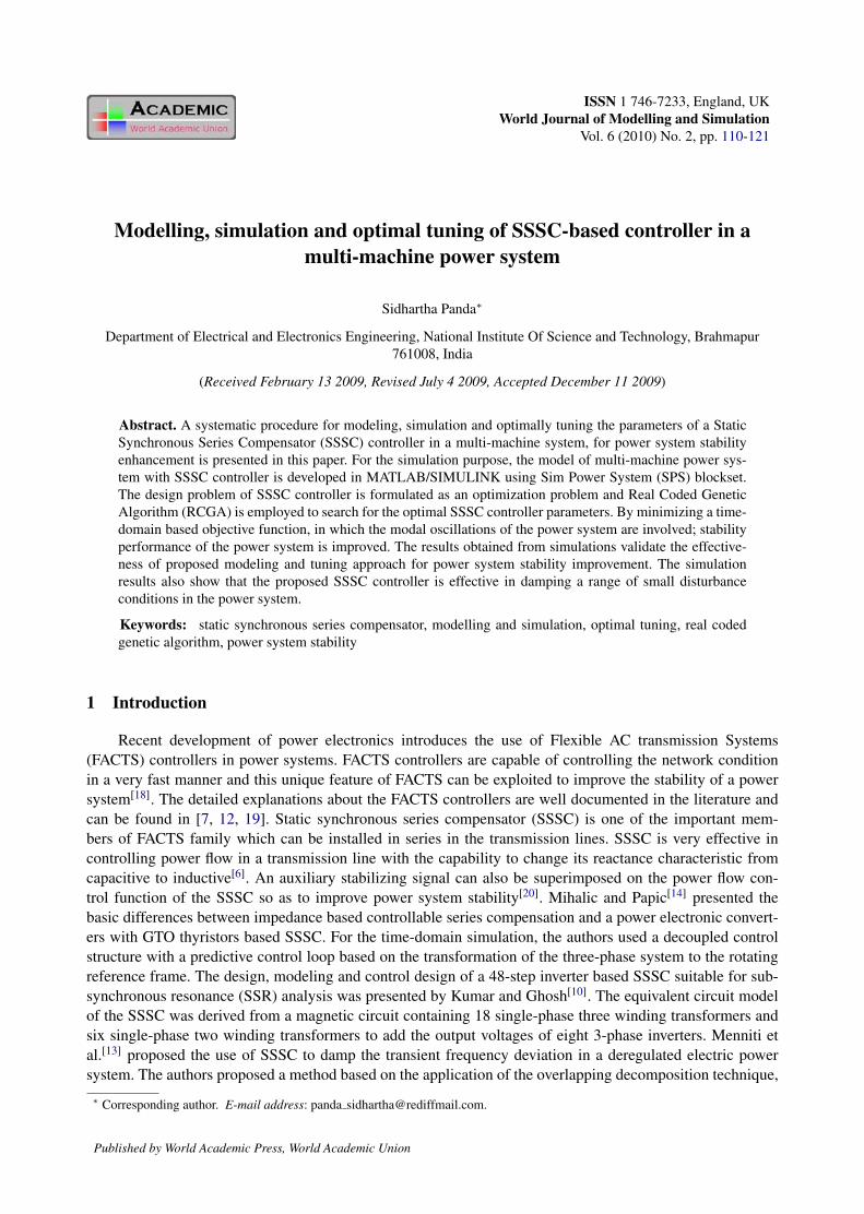
A 3-cycle, 3-phase fault is applied at one of the line sections between bus1 and bus 6 near bus 6 at t = 1 s. The fault is cleared by opening the faulty line and the line is reclosed after 3-cycles. Figs. 6-8 show the variations of the inter-area and local mode of oscillation against time. From these Figs. it can be seen that, inter-area modes of oscillations are highly oscillatory in the absence of SSSC-based damping controller and the controller significantly improves the power system stability by damping these oscillations. Further, the proposed controller is also effective in suppressing the local mode of oscillations. The SSSC
Fig. 5. Convergence of fitness function
legend ‘NC’ and response with GA optimized SSSC-based damping controller is shown with solid lines withlegend ‘SSSC’. The following cases are considered:
Case 1: three-phase fault disturbance
A 3-cycle, 3-phase fault is applied at one of the line sections between bus1 and bus 6 near bus 6 at t = 1s.The fault is cleared by opening the faulty line and the line is reclosed after 3-cycles. Fig. 6 ∼ Fig. 8 show thevariations of the inter-area and local mode of oscillation against time. From these Figs. it can be seen that,inter-area modes of oscillations are highly oscillatory in the absence of SSSC-based damping controller andthe controller significantly improves the power system stability by damping these oscillations. Further, theproposed controller is also effective in suppressing the local mode of oscillations. The SSSC injected voltageVq for the above contingency is shown in Fig. 9 which shows that Vq is effectively modulated to suppresspower system oscillations.
Case 2: small disturbance
In order to examine the effectiveness of the proposed controller under small disturbance, the load at bus4 is disconnected at t = 0.1s for 50 ms. Fig. 10 and Fig. 11 show the inter-area and local modes of oscillationsagainst time, from which it is clear that the SSSC-based damping controller damps the modal oscillationseffectively even for small disturbance.
Case 3: unbalanced fault disturbance
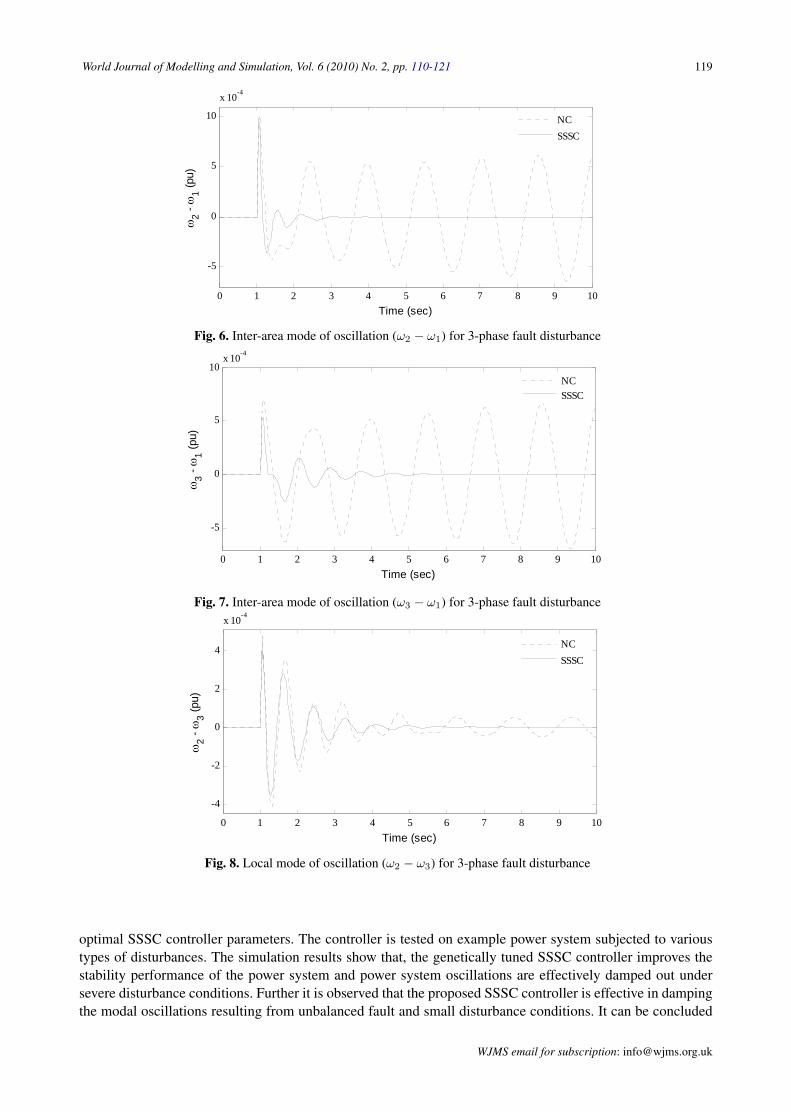
The effectiveness of the proposed controller to unbalanced faults is also examined by applying self clear-ing type unsymmetrical faults (namely double line-to-ground, line-to-line and single line-to-ground) of 3-cycleduration, at bus 1. The inter-area and local modes of oscillations against time are shown in Fig. 12 and Fig.13 respectively. In these Figs., the uncontrolled system response for least severe single line-to-ground faultis also shown with dotted lines. It is clear from the simulation results that the modal oscillations are poorlydamped in uncontrolled case even for the least severe fault and the SSSC-based damping controller effectivelystabilizes the modal oscillations under various unbalanced fault conditions.
6 Conclusions
This paper presents a systematic procedure for modeling, simulation and optimal tuning of SSSC con-troller in a multi- machine system for enhancing power system stability. For the SSSC controller design prob-lem, a parameter-constrained, time-domain based, objective function, is developed to improve the performanceof power system subjected to a disturbance. Then, real coded genetic algorithm employed to search for the
WJMS email for contribution: [email protected]
World Journal of Modelling and Simulation, Vol. 6 (2010) No. 2, pp. 110-121 119
injected voltage Vq for the above contingency is shown in Fig. 9 which shows that Vq is effectively modulated to suppress power system oscillations.
0 1 2 3 4 5 6 7 8 9 10
-5
0
5
10
x 10-4
Time (sec)
ω2 -
ω1 (p
u)
NCSSSC
Fig. 6: Inter-area mode of oscillation ( 12 ω−ω ) for 3-phase fault disturbance
0 1 2 3 4 5 6 7 8 9 10
-5
0
5
10x 10-4
Time (sec)
ω3 -
ω1 (p
u)
NCSSSC
Fig. 7: Inter-area mode of oscillation ( 13 ω−ω ) for 3-phase fault disturbance
0 1 2 3 4 5 6 7 8 9 10
-4
-2
0
2
4
x 10-4
Time (sec)
ω2 -
ω3 (p
u)
NCSSSC
Fig. 8: Local mode of oscillation ( 32 ω−ω ) for 3-phase fault disturbance
Fig. 6. Inter-area mode of oscillation (ω2 − ω1) for 3-phase fault disturbance
injected voltage Vq for the above contingency is shown in Fig. 9 which shows that Vq is effectively modulated to suppress power system oscillations.
0 1 2 3 4 5 6 7 8 9 10
-5
0
5
10
x 10-4
Time (sec)
ω2 -
ω1 (p
u)
NCSSSC
Fig. 6: Inter-area mode of oscillation ( 12 ω−ω ) for 3-phase fault disturbance
0 1 2 3 4 5 6 7 8 9 10
-5
0
5
10x 10-4
Time (sec)
ω3 -
ω1 (p
u)
NCSSSC
Fig. 7: Inter-area mode of oscillation ( 13 ω−ω ) for 3-phase fault disturbance
0 1 2 3 4 5 6 7 8 9 10
-4
-2
0
2
4
x 10-4
Time (sec)
ω2 -
ω3 (p
u)
NCSSSC
Fig. 8: Local mode of oscillation ( 32 ω−ω ) for 3-phase fault disturbance
Fig. 7. Inter-area mode of oscillation (ω3 − ω1) for 3-phase fault disturbance
injected voltage Vq for the above contingency is shown in Fig. 9 which shows that Vq is effectively modulated to suppress power system oscillations.
0 1 2 3 4 5 6 7 8 9 10
-5
0
5
10
x 10-4
Time (sec)
ω2 -
ω1 (p
u)
NCSSSC
Fig. 6: Inter-area mode of oscillation ( 12 ω−ω ) for 3-phase fault disturbance
0 1 2 3 4 5 6 7 8 9 10
-5
0
5
10x 10-4
Time (sec)
ω3 -
ω1 (p
u)
NCSSSC
Fig. 7: Inter-area mode of oscillation ( 13 ω−ω ) for 3-phase fault disturbance
0 1 2 3 4 5 6 7 8 9 10
-4
-2
0
2
4
x 10-4
Time (sec)
ω2 -
ω3 (p
u)
NCSSSC
Fig. 8: Local mode of oscillation ( 32 ω−ω ) for 3-phase fault disturbance Fig. 8. Local mode of oscillation (ω2 − ω3) for 3-phase fault disturbance
optimal SSSC controller parameters. The controller is tested on example power system subjected to varioustypes of disturbances. The simulation results show that, the genetically tuned SSSC controller improves thestability performance of the power system and power system oscillations are effectively damped out undersevere disturbance conditions. Further it is observed that the proposed SSSC controller is effective in dampingthe modal oscillations resulting from unbalanced fault and small disturbance conditions. It can be concluded
WJMS email for subscription: [email protected]

120 S. Panda: SSSC-based controller in a multi-machine power system
0 1 2 3 4 5 6 7
-0.05
0
0.05
0.1
0.15
0.2
Time (sec)
Vq (p
u)
NCSSSC
Fig. 9: SSSC injected voltage ( qV ) variation for 3-phase fault disturbance
Case 2: Small disturbance
In order to examine the effectiveness of the proposed controller under small disturbance, the load at bus 4 is disconnected at t = 0.1 s for 50 ms. Figs. 10 and 11 show the inter-area and local modes of oscillations against time, from which it is clear that the SSSC-based damping controller damps the modal oscillations effectively even for small disturbance.
0 1 2 3 4 5 6 7
-3
-2
-1
0
1
2
3
x 10-4
Time (sec)
ω2 -
ω1 (p
u)
NCSSSC
Fig. 10: Inter-area mode of oscillation ( 12 ω−ω ) for small disturbance
0 1 2 3 4 5 6 7 8-8
-6
-4
-2
0
2
4
6
8x 10⁻⁵
Time (sec)
ω2 -
ω3 (p
u)
NCSSSC
Fig. 11: Local mode of oscillation ( 32 ω−ω ) for small disturbance
Fig. 9. SSSC injected voltage (Vq) variation for 3-phase fault disturbance
0 1 2 3 4 5 6 7
-0.05
0
0.05
0.1
0.15
0.2
Time (sec)V
q (pu)
NCSSSC
Fig. 9: SSSC injected voltage ( qV ) variation for 3-phase fault disturbance
Case 2: Small disturbance
In order to examine the effectiveness of the proposed controller under small disturbance, the load at bus 4 is disconnected at t = 0.1 s for 50 ms. Figs. 10 and 11 show the inter-area and local modes of oscillations against time, from which it is clear that the SSSC-based damping controller damps the modal oscillations effectively even for small disturbance.
0 1 2 3 4 5 6 7
-3
-2
-1
0
1
2
3
x 10-4
Time (sec)
ω2 -
ω1 (p
u)
NCSSSC
Fig. 10: Inter-area mode of oscillation ( 12 ω−ω ) for small disturbance
0 1 2 3 4 5 6 7 8-8
-6
-4
-2
0
2
4
6
8x 10⁻⁵
Time (sec)
ω2 -
ω3 (p
u)
NCSSSC
Fig. 11: Local mode of oscillation ( 32 ω−ω ) for small disturbance
Fig. 10. Inter-area mode of oscillation (ω2 − ω1) for small disturbance
0 1 2 3 4 5 6 7
-0.05
0
0.05
0.1
0.15
0.2
Time (sec)
Vq (p
u)
NCSSSC
Fig. 9: SSSC injected voltage ( qV ) variation for 3-phase fault disturbance
Case 2: Small disturbance
In order to examine the effectiveness of the proposed controller under small disturbance, the load at bus 4 is disconnected at t = 0.1 s for 50 ms. Figs. 10 and 11 show the inter-area and local modes of oscillations against time, from which it is clear that the SSSC-based damping controller damps the modal oscillations effectively even for small disturbance.
0 1 2 3 4 5 6 7
-3
-2
-1
0
1
2
3
x 10-4
Time (sec)
ω2 -
ω1 (p
u)
NCSSSC
Fig. 10: Inter-area mode of oscillation ( 12 ω−ω ) for small disturbance
0 1 2 3 4 5 6 7 8-8
-6
-4
-2
0
2
4
6
8x 10⁻⁵
Time (sec)
ω2 -
ω3 (p
u)
NCSSSC
Fig. 11: Local mode of oscillation ( 32 ω−ω ) for small disturbance Fig. 11. Local mode of oscillation (ω2 − ω3) for small disturbance
that, the local and inter-area modes of oscillations of power system can be effectively damped for variousdisturbances by using the proposed SSSC controller.
References
[1] Sim Power Systems 4.3, User’s guide. Http://www.mathworks.com/products/simpower/.[2] Y. Abdel-Magid, M. Abido. Robust coordinated design of excitation and TCSC-based stabilizers using genetic
algorithms. Electrical Power and Energy Systems, 2004, 69(2-3): 129–141.
WJMS email for contribution: [email protected]
World Journal of Modelling and Simulation, Vol. 6 (2010) No. 2, pp. 110-121 121
Case 3: Unbalanced fault disturbance
The effectiveness of the proposed controller to unbalanced faults is also examined by applying self clearing type unsymmetrical faults (namely double line-to-ground, line-to-line and single line-to-ground) of 3-cycle duration, at bus 1. The inter-area and local modes of oscillations against time are shown in Figs. 12 and 13 respectively. In these Figs., the uncontrolled system response for least severe single line-to-ground fault is also shown with dotted lines. It is clear from the simulation results that the modal oscillations are poorly damped in uncontrolled case even for the least severe fault and the SSSC-based damping controller effectively stabilizes the modal oscillations under various unbalanced fault conditions.
0 0.5 1 1.5 2 2.5 3 3.5 4 4.5 5-2
-1
0
1
2
3x 10⁻⁴
Time (sec)
ω2 -
ω1 (p
u)
1: L-L-G fault2: L-L fault3: L-G fault4: L-G fault uncontrolled
1
2
3 4
Fig. 12: Inter-area mode of oscillation ( 12 ω−ω ) for small disturbance
0 1 2 3 4 5 6-2
-1
0
1
2
x 10-4
Time (sec)
ω2 -
ω3 (p
u)
1
2
3
4
1: L-L-G fault2: L-L fault3: L-G fault4: L-G fault uncontrolled
Fig. 13: Local mode of oscillation ( 32 ω−ω ) for small disturbance
6. Conclusions This paper presents a systematic procedure for modeling, simulation and optimal tuning of SSSC controller in a multi- machine system for enhancing power system stability. For the SSSC controller design problem, a parameter-constrained, time-domain based, objective function, is developed to improve the performance of power system subjected to a disturbance. Then, real coded genetic algorithm employed to search for the optimal SSSC controller parameters. The controller is tested on example power system subjected to various types of disturbances. The simulation results show that, the genetically tuned SSSC controller improves the stability performance of the power
Fig. 12. Inter-area mode of oscillation (ω2 − ω1) for small disturbance
Case 3: Unbalanced fault disturbance
The effectiveness of the proposed controller to unbalanced faults is also examined by applying self clearing type unsymmetrical faults (namely double line-to-ground, line-to-line and single line-to-ground) of 3-cycle duration, at bus 1. The inter-area and local modes of oscillations against time are shown in Figs. 12 and 13 respectively. In these Figs., the uncontrolled system response for least severe single line-to-ground fault is also shown with dotted lines. It is clear from the simulation results that the modal oscillations are poorly damped in uncontrolled case even for the least severe fault and the SSSC-based damping controller effectively stabilizes the modal oscillations under various unbalanced fault conditions.
0 0.5 1 1.5 2 2.5 3 3.5 4 4.5 5-2
-1
0
1
2
3x 10⁻⁴
Time (sec)
ω2 -
ω1 (p
u)
1: L-L-G fault2: L-L fault3: L-G fault4: L-G fault uncontrolled
1
2
3 4
Fig. 12: Inter-area mode of oscillation ( 12 ω−ω ) for small disturbance
0 1 2 3 4 5 6-2
-1
0
1
2
x 10-4
Time (sec)
ω2 -
ω3 (p
u)
1
2
3
4
1: L-L-G fault2: L-L fault3: L-G fault4: L-G fault uncontrolled
Fig. 13: Local mode of oscillation ( 32 ω−ω ) for small disturbance
6. Conclusions This paper presents a systematic procedure for modeling, simulation and optimal tuning of SSSC controller in a multi- machine system for enhancing power system stability. For the SSSC controller design problem, a parameter-constrained, time-domain based, objective function, is developed to improve the performance of power system subjected to a disturbance. Then, real coded genetic algorithm employed to search for the optimal SSSC controller parameters. The controller is tested on example power system subjected to various types of disturbances. The simulation results show that, the genetically tuned SSSC controller improves the stability performance of the power
Fig. 13. Local mode of oscillation (ω2 − ω3) for small disturbance
[3] M. Abido. Analysis and assessment of STATCOM-based damping stabilizers for power system stability enhance-ment. Electric Power Systems Research, 2005, 73: 177–185.
[4] M. Castro, H. Ayres, et al. Impacts of the SSSC control modes on small-signal transient stability of a power system.Electric Power System Research, 2007, 77: 1–9.
[5] D. Goldberg. Genetic Algorithms in Search, Optimization, and Machine Learning. M. A: Addison-Wesley, Boston,1989.
[6] L. Gyugyi, C. Schauder, K. Sen. Static synchronous series compensator: a solid-state approach to the series com-pensation of transmission lines. IEEE Transactions on Power Delivery, 1997, 12(1): 406–417.
[7] N. Hingoran, L. Gyugyi. Understanding FACTS: Concepts and Technology of Flexible AC Transmission Systems.IEEE Press, New York, 2000.
[8] F. Jowder. Influence of mode of operation of the SSSC on the small disturbance and transient stability of a radialpower system. IEEE Transactions on Power Systems, 2005, 20(2): 935–942.
[9] F. Jowder, B. Ooi. Series compensation of radial power system by a combination of sssc and dielectric capacitors.IEEE Transactions on Power Delivery, 2005, 20(1): 458–465.
[10] L. S. Kumar, A. Ghosh. Static synchronous series compensator-design, control and application. Electric PowerSystem Research, 1999, 49: 139–148.
[11] P. Kundur. Power System Stability and Control. McGraw-Hill, New York, 1994.[12] R. Mathur, R. Verma. Thyristor-based FACTS Controllers for Electrical Transmission Systems. IEEE press, Pis-
cataway, 2002.[13] D. Menniti, A. Pinnarelli, et al. Using a FACTS device controlled by a decentralized control law to damp the
transient frequency deviation in a deregulated electric power system. Electric Power System Research, 2004, 72:289–298.
[14] R. Mihalic, I. Papic. Static synchronous series compensator-a mean for dynamic power flow control in electricpower systems. Electric Power System Research, 1998, 45: 65–72.
WJMS email for subscription: [email protected]

122 S. Panda: SSSC-based controller in a multi-machine power system
[15] S. Mishra, P. Dash, et al. Genetically optimized neuro-fuzzy IPFC for damping modal oscillations of power sys-tems. IEEE Transactions on Power Systems, 2002, 17(4): 1140–1147.
[16] I. Ngamroo, J. Tippayachai, S. Dechanupaprittha. Robust decentralised frequency stabilizers design of static syn-chronous series compensators by taking system uncertainties into consideration. International Journal of ElectricalPower and Energy Systems , 2006, 28: 513–524.
[17] M. Noroozian, G. Anderson, K. Tomsovic. Robust near-optimal control of power system oscillation with fuzzylogic. IEEE Transactions on Power Delivery , 1996, 11(1): 393–400.
[18] S. Panda, N. Padhy, R. Patel. Modelling, simulation and optimal tuning of TCSC controller. International Journalof Simulation Modelling, 2007, 6(1): 37–48.
[19] Y. Song, T. Johns. Flexible AC Transmission Systems (FACTS). IEE, London, 2000.[20] H. Wang. Static synchronous series compensator to damp power system oscillations. Electric Power System
Research, 2000, 54: 113–119.
Appendix
A complete list of parameters used appears in the default options of Sim Power Systems in the User’sManual[1]. All data are in pu unless specified otherwise.
Generators
SB1 = 4200MVA, SB2 = SB3 = 2100WVA, H = 3.7s, VB = 13.8kV,f = 60Hz, RS = 2.8544e−3, Xd = 1.305, X
′d = 0.296, X
′′d = 0.252,
Xq = 0.474, X′q = 0.243, X
′′q = 0.18, Td = 1.01 s, T
′d = 0.053 s,
T′′qo = 0.1 s, Pe1 = 0.3048, Pe2 = 0.2095, Pe3 = 0.1445
LoadsLoad1 = 15000MW + 1500MVAR, Load2 = Load3 = 25MW,Load4 = 250MW
TransformersSBT1 = 2100MVA, SBT2 = SBT3 = 2100MVA, 13.8/500kV , 60Hz,R1 = R2 = 0.002, L1 = 0, L2 = 0.12, D1/Ygconnection,Rm = 500, Lm = 500
Transmission lines3-Ph, 60Hz, L1 = 175km, L2 = 50km, L3 = 100km,R1 = 0.02546Ω/km, R0 = 0.3864Ω/km, L1 = 0.9337e−3H/km,L0 = 4.1264e−3H/km, C1 = 12.74e−9F/km, C0 = 7.751e−9F/km
Hydraulic Turbine andGovernor
Ka = 3.33, Ta = 0.07, Gmin = 0.01, Gmax = 0.97518,V gmin = −0.1pu/s, Vgmax = 0.1pu/s, Rp = 0.05, Kp = 1.163,Ki = 0.105, Kd = 0, Td = 0.01s, β = 0, Tw = 2.67 s
Excitation SystemTLP = 0.02s, Ka = 200, Ta = 0.001s, Ke = 1, Te = 0, Tb = 0,Tc = 0, Kf = 0.001, Tf = 0.1s, Efmin = 0, Efmax = 7, Kp = 0
SSSC
Snom = 100MVA, Vnom = 500kV, f = 60Hz, Vqmax = 0.2,Max rate of change ofVqref = 3/s, Rcnv = 0.00533, Lcnv = 0.16,VDC = 40kV, CDC = 375e−6 F, KP IVR = 0.00375, KI IVR = 0.1875,KP VdcR = 0.1e−3, KP VdcR20e−3
WJMS email for contribution: [email protected]