modernizing rpg applications using x-analysis suite · ibm.com/redbooks redpaper modernizing and...
TRANSCRIPT

ibm.com/redbooks Redpaper
Modernizing and Improving the Maintainability of RPG Applications Using X-Analysis Version 5.6
LindaMay PattersonHiroshi Araki
Stuart BramleyGene Cobb
Joel EikenhorstStuart MilliganJames SimonsMark Tregear
Graphically analyze application architecture
Extract business rule logic and application data models
Modularize existing code into the MVC architecture


International Technical Support Organization
Modernizing And Improving the Maintainability of RPG Applications using X-Analysis Version 5.6
February 2006

© Copyright International Business Machines Corporation 2006. All rights reserved.Note to U.S. Government Users Restricted Rights -- Use, duplication or disclosure restricted by GSA ADP ScheduleContract with IBM Corp.
First Edition (February 2006)
This edition applies to Version 5 Release 6 of X-Analysis from Databorough Ltd.
Note: Before using this information and the product it supports, read the information in “Notices” on page vii.
Contents
Notices . . . . . . . . . . . . . . . . . . . . . . . . . . . . . . . . . . . . . . . . . . . . . . . . . . . . . . . . . . . . . . . . . viiTrademarks . . . . . . . . . . . . . . . . . . . . . . . . . . . . . . . . . . . . . . . . . . . . . . . . . . . . . . . . . . . . . viii
Preface . . . . . . . . . . . . . . . . . . . . . . . . . . . . . . . . . . . . . . . . . . . . . . . . . . . . . . . . . . . . . . . . . ixThe team that wrote this Redpaper . . . . . . . . . . . . . . . . . . . . . . . . . . . . . . . . . . . . . . . . . . . . .xBecome a published author . . . . . . . . . . . . . . . . . . . . . . . . . . . . . . . . . . . . . . . . . . . . . . . . . . xiiComments welcome. . . . . . . . . . . . . . . . . . . . . . . . . . . . . . . . . . . . . . . . . . . . . . . . . . . . . . . . xii
Chapter 1. Overview: modernization and X-Analysis . . . . . . . . . . . . . . . . . . . . . . . . . . . 11.1 Why modernize an existing application?. . . . . . . . . . . . . . . . . . . . . . . . . . . . . . . . . . . . . 2
1.1.1 Modern application considerations . . . . . . . . . . . . . . . . . . . . . . . . . . . . . . . . . . . . . 21.2 Architecture a modern application. . . . . . . . . . . . . . . . . . . . . . . . . . . . . . . . . . . . . . . . . . 4
1.2.1 Using stateless programs . . . . . . . . . . . . . . . . . . . . . . . . . . . . . . . . . . . . . . . . . . . . 51.3 Service-oriented architecture . . . . . . . . . . . . . . . . . . . . . . . . . . . . . . . . . . . . . . . . . . . . . 61.4 General principles for automated modernization projects . . . . . . . . . . . . . . . . . . . . . . . . 71.5 Introducing X-Analysis . . . . . . . . . . . . . . . . . . . . . . . . . . . . . . . . . . . . . . . . . . . . . . . . . . 8
1.5.1 X-Analysis components . . . . . . . . . . . . . . . . . . . . . . . . . . . . . . . . . . . . . . . . . . . . . 91.6 X-Analysis and the iSeries Developer Roadmap . . . . . . . . . . . . . . . . . . . . . . . . . . . . . 11
1.6.1 Future tools view of the iSeries Developer Roadmap. . . . . . . . . . . . . . . . . . . . . . 121.6.2 X-Analysis and the roadmap. . . . . . . . . . . . . . . . . . . . . . . . . . . . . . . . . . . . . . . . . 13
1.7 X-Analysis modernization scenarios . . . . . . . . . . . . . . . . . . . . . . . . . . . . . . . . . . . . . . . 141.7.1 Business scenario 1 . . . . . . . . . . . . . . . . . . . . . . . . . . . . . . . . . . . . . . . . . . . . . . . 141.7.2 Business scenario 2 . . . . . . . . . . . . . . . . . . . . . . . . . . . . . . . . . . . . . . . . . . . . . . . 141.7.3 Business scenario 3 . . . . . . . . . . . . . . . . . . . . . . . . . . . . . . . . . . . . . . . . . . . . . . . 14
Chapter 2. Introducing the sample application . . . . . . . . . . . . . . . . . . . . . . . . . . . . . . . 152.1 About the sample application . . . . . . . . . . . . . . . . . . . . . . . . . . . . . . . . . . . . . . . . . . . . 162.2 Overview of the Customer Management System . . . . . . . . . . . . . . . . . . . . . . . . . . . . . 16
2.2.1 Customers Main Menu . . . . . . . . . . . . . . . . . . . . . . . . . . . . . . . . . . . . . . . . . . . . . 162.2.2 Data files associated with Customers Main Menu . . . . . . . . . . . . . . . . . . . . . . . . 302.2.3 Programs associated with the Customers Main Menu . . . . . . . . . . . . . . . . . . . . . 30
2.3 The XRAPPS Library . . . . . . . . . . . . . . . . . . . . . . . . . . . . . . . . . . . . . . . . . . . . . . . . . . 312.3.1 Data files . . . . . . . . . . . . . . . . . . . . . . . . . . . . . . . . . . . . . . . . . . . . . . . . . . . . . . . . 312.3.2 Source and object files . . . . . . . . . . . . . . . . . . . . . . . . . . . . . . . . . . . . . . . . . . . . . 32
Chapter 3. Re-engineering an existing application to the MVC architecture . . . . . . . 353.1 Prerequisites for MVC re-engineering. . . . . . . . . . . . . . . . . . . . . . . . . . . . . . . . . . . . . . 363.2 Application re-engineering overview . . . . . . . . . . . . . . . . . . . . . . . . . . . . . . . . . . . . . . . 37
3.2.1 The Model-View-Controller architecture . . . . . . . . . . . . . . . . . . . . . . . . . . . . . . . . 373.2.2 Creating the Model . . . . . . . . . . . . . . . . . . . . . . . . . . . . . . . . . . . . . . . . . . . . . . . . 383.2.3 Creating the View and Controller . . . . . . . . . . . . . . . . . . . . . . . . . . . . . . . . . . . . . 383.2.4 Working with function definitions. . . . . . . . . . . . . . . . . . . . . . . . . . . . . . . . . . . . . . 39
3.3 Example application . . . . . . . . . . . . . . . . . . . . . . . . . . . . . . . . . . . . . . . . . . . . . . . . . . . 403.4 X-Analysis MVC re-engineering summary . . . . . . . . . . . . . . . . . . . . . . . . . . . . . . . . . . 413.5 Partitioning the application . . . . . . . . . . . . . . . . . . . . . . . . . . . . . . . . . . . . . . . . . . . . . . 41
3.5.1 Creating the application area . . . . . . . . . . . . . . . . . . . . . . . . . . . . . . . . . . . . . . . . 423.5.2 Adding the Customers Main Menu to the application area . . . . . . . . . . . . . . . . . . 43
3.6 Reviewing the application’s standard function definitions . . . . . . . . . . . . . . . . . . . . . . . 453.6.1 Viewing the standard function definitions . . . . . . . . . . . . . . . . . . . . . . . . . . . . . . . 45
© Copyright IBM Corp. 2006. All rights reserved. iii
3.6.2 Standard function definition naming conventions . . . . . . . . . . . . . . . . . . . . . . . . . 463.6.3 Associated stored procedures . . . . . . . . . . . . . . . . . . . . . . . . . . . . . . . . . . . . . . . 473.6.4 Displaying the function layout . . . . . . . . . . . . . . . . . . . . . . . . . . . . . . . . . . . . . . . . 47
3.7 Customizing the standard function definitions. . . . . . . . . . . . . . . . . . . . . . . . . . . . . . . . 493.7.1 Customizing the Grid SFD . . . . . . . . . . . . . . . . . . . . . . . . . . . . . . . . . . . . . . . . . . 493.7.2 Customizing the Flat Screen SDF. . . . . . . . . . . . . . . . . . . . . . . . . . . . . . . . . . . . . 55
3.8 Running the X-Analysis MVC re-engineering process . . . . . . . . . . . . . . . . . . . . . . . . . 603.8.1 Running the MVC re-engineering process over an application area. . . . . . . . . . . 603.8.2 Running the MVC re-engineering process over an individual program. . . . . . . . . 62
3.9 Reviewing the re-engineered function definitions . . . . . . . . . . . . . . . . . . . . . . . . . . . . . 643.9.1 Re-engineered function definition naming conventions . . . . . . . . . . . . . . . . . . . . 653.9.2 Viewing the function layout . . . . . . . . . . . . . . . . . . . . . . . . . . . . . . . . . . . . . . . . . . 65
3.10 Reviewing the re-engineered stored procedures . . . . . . . . . . . . . . . . . . . . . . . . . . . . 703.10.1 Re-engineered stored procedure naming conventions . . . . . . . . . . . . . . . . . . . . 713.10.2 Linking a re-engineered stored procedure to a function definition . . . . . . . . . . . 713.10.3 Reviewing the re-engineered stored procedure source code . . . . . . . . . . . . . . . 72
3.11 Customizing the re-engineered function definitions . . . . . . . . . . . . . . . . . . . . . . . . . . 733.11.1 Customizing the Grid RFD . . . . . . . . . . . . . . . . . . . . . . . . . . . . . . . . . . . . . . . . . 733.11.2 Customizing the Flat Screen RFD. . . . . . . . . . . . . . . . . . . . . . . . . . . . . . . . . . . . 77
3.12 Web-enabling the application using the X-Web framework. . . . . . . . . . . . . . . . . . . . . 803.12.1 Starting and configuring the X-Web server . . . . . . . . . . . . . . . . . . . . . . . . . . . . . 813.12.2 The Web-enabled application Web pages . . . . . . . . . . . . . . . . . . . . . . . . . . . . . 83
3.13 Implementing the Web-enabled application in Java . . . . . . . . . . . . . . . . . . . . . . . . . . 933.13.1 Java components . . . . . . . . . . . . . . . . . . . . . . . . . . . . . . . . . . . . . . . . . . . . . . . . 933.13.2 Generating the Java components . . . . . . . . . . . . . . . . . . . . . . . . . . . . . . . . . . . . 943.13.3 Working with the Java components in WDSc . . . . . . . . . . . . . . . . . . . . . . . . . . . 963.13.4 Viewing the application JSF . . . . . . . . . . . . . . . . . . . . . . . . . . . . . . . . . . . . . . . . 993.13.5 How the JavaServer Faces application works . . . . . . . . . . . . . . . . . . . . . . . . . 102
Chapter 4. Application maintainability and re-engineering. . . . . . . . . . . . . . . . . . . . . 1134.1 Introducing the X-Analysis cross-reference repository . . . . . . . . . . . . . . . . . . . . . . . . 1144.2 Integrated maintenance environment . . . . . . . . . . . . . . . . . . . . . . . . . . . . . . . . . . . . . 114
4.2.1 Variable Where Used . . . . . . . . . . . . . . . . . . . . . . . . . . . . . . . . . . . . . . . . . . . . . 1144.3 Application analysis and documentation . . . . . . . . . . . . . . . . . . . . . . . . . . . . . . . . . . . 124
4.3.1 Data Flow Diagrams (DFD). . . . . . . . . . . . . . . . . . . . . . . . . . . . . . . . . . . . . . . . . 1254.3.2 Structure Chart Diagram (SCD) . . . . . . . . . . . . . . . . . . . . . . . . . . . . . . . . . . . . . 127
4.4 Program analysis and understanding . . . . . . . . . . . . . . . . . . . . . . . . . . . . . . . . . . . . . 1344.4.1 The Source Browser . . . . . . . . . . . . . . . . . . . . . . . . . . . . . . . . . . . . . . . . . . . . . . 1344.4.2 Variable Where Used . . . . . . . . . . . . . . . . . . . . . . . . . . . . . . . . . . . . . . . . . . . . . 1364.4.3 Member X-Reference . . . . . . . . . . . . . . . . . . . . . . . . . . . . . . . . . . . . . . . . . . . . . 1374.4.4 Viewing Source at different detail levels . . . . . . . . . . . . . . . . . . . . . . . . . . . . . . . 1384.4.5 Indented Source . . . . . . . . . . . . . . . . . . . . . . . . . . . . . . . . . . . . . . . . . . . . . . . . . 1404.4.6 Pseudo Code Displays . . . . . . . . . . . . . . . . . . . . . . . . . . . . . . . . . . . . . . . . . . . . 1414.4.7 Program flowcharts . . . . . . . . . . . . . . . . . . . . . . . . . . . . . . . . . . . . . . . . . . . . . . . 1424.4.8 Microsoft Visio flow charts. . . . . . . . . . . . . . . . . . . . . . . . . . . . . . . . . . . . . . . . . . 1434.4.9 Business rules. . . . . . . . . . . . . . . . . . . . . . . . . . . . . . . . . . . . . . . . . . . . . . . . . . . 143
4.5 Using X-Analysis cross-reference repository for modernizing. . . . . . . . . . . . . . . . . . . 1474.5.1 X-Analysis cross-reference repository details . . . . . . . . . . . . . . . . . . . . . . . . . . . 1474.5.2 Using the repository: an example program . . . . . . . . . . . . . . . . . . . . . . . . . . . . . 150
4.6 Performing field re-engineering. . . . . . . . . . . . . . . . . . . . . . . . . . . . . . . . . . . . . . . . . . 1594.6.1 Creating a new resizing project. . . . . . . . . . . . . . . . . . . . . . . . . . . . . . . . . . . . . . 1604.6.2 Initializing the resize project . . . . . . . . . . . . . . . . . . . . . . . . . . . . . . . . . . . . . . . . 1614.6.3 Identifying fields to change . . . . . . . . . . . . . . . . . . . . . . . . . . . . . . . . . . . . . . . . . 162
iv Modernizing And Improving the Maintainability of RPG Applications using X-Analysis Version 5.6

4.6.4 Explicitly identifying fields to change. . . . . . . . . . . . . . . . . . . . . . . . . . . . . . . . . . 1674.6.5 Building list of objects to be converted . . . . . . . . . . . . . . . . . . . . . . . . . . . . . . . . 1744.6.6 Running a conversion . . . . . . . . . . . . . . . . . . . . . . . . . . . . . . . . . . . . . . . . . . . . . 1774.6.7 Identifying potential problems . . . . . . . . . . . . . . . . . . . . . . . . . . . . . . . . . . . . . . . 1894.6.8 Import converted library into change management system . . . . . . . . . . . . . . . . 194
Chapter 5. Recovering application design . . . . . . . . . . . . . . . . . . . . . . . . . . . . . . . . . . 1955.1 Modernization and maintenance through modelling . . . . . . . . . . . . . . . . . . . . . . . . . . 1965.2 Recovering the data model design . . . . . . . . . . . . . . . . . . . . . . . . . . . . . . . . . . . . . . . 196
5.2.1 Tuning the data model with XDMODEL . . . . . . . . . . . . . . . . . . . . . . . . . . . . . . . 1965.3 Application areas. . . . . . . . . . . . . . . . . . . . . . . . . . . . . . . . . . . . . . . . . . . . . . . . . . . . . 1975.4 Defining application areas. . . . . . . . . . . . . . . . . . . . . . . . . . . . . . . . . . . . . . . . . . . . . . 1975.5 Exploring the application data model . . . . . . . . . . . . . . . . . . . . . . . . . . . . . . . . . . . . . 200
5.5.1 Adjusting the generated data model . . . . . . . . . . . . . . . . . . . . . . . . . . . . . . . . . . 2055.6 Exploring the data in the database . . . . . . . . . . . . . . . . . . . . . . . . . . . . . . . . . . . . . . . 2085.7 Measuring referential integrity . . . . . . . . . . . . . . . . . . . . . . . . . . . . . . . . . . . . . . . . . . . 2115.8 Recovering application design structure . . . . . . . . . . . . . . . . . . . . . . . . . . . . . . . . . . . 2125.9 Recovering business rules . . . . . . . . . . . . . . . . . . . . . . . . . . . . . . . . . . . . . . . . . . . . . 214
Chapter 6. Using the recovered model . . . . . . . . . . . . . . . . . . . . . . . . . . . . . . . . . . . . . 2196.1 Exporting the data model . . . . . . . . . . . . . . . . . . . . . . . . . . . . . . . . . . . . . . . . . . . . . . 220
6.1.1 Exporting XML Metadata Interchange . . . . . . . . . . . . . . . . . . . . . . . . . . . . . . . . 2206.1.2 Exporting DDL. . . . . . . . . . . . . . . . . . . . . . . . . . . . . . . . . . . . . . . . . . . . . . . . . . . 2216.1.3 Exporting to Microsoft Visio. . . . . . . . . . . . . . . . . . . . . . . . . . . . . . . . . . . . . . . . . 223
6.2 Using the X-Analysis database . . . . . . . . . . . . . . . . . . . . . . . . . . . . . . . . . . . . . . . . . . 2236.2.1 The data model database . . . . . . . . . . . . . . . . . . . . . . . . . . . . . . . . . . . . . . . . . . 2246.2.2 Using X-Browse to explore the data model database. . . . . . . . . . . . . . . . . . . . . 228
6.3 Using the business rules database . . . . . . . . . . . . . . . . . . . . . . . . . . . . . . . . . . . . . . . 2296.3.1 Level 1 . . . . . . . . . . . . . . . . . . . . . . . . . . . . . . . . . . . . . . . . . . . . . . . . . . . . . . . . 2296.3.2 Level 2 . . . . . . . . . . . . . . . . . . . . . . . . . . . . . . . . . . . . . . . . . . . . . . . . . . . . . . . . 2346.3.3 Level 3 . . . . . . . . . . . . . . . . . . . . . . . . . . . . . . . . . . . . . . . . . . . . . . . . . . . . . . . . 2366.3.4 Level 4 . . . . . . . . . . . . . . . . . . . . . . . . . . . . . . . . . . . . . . . . . . . . . . . . . . . . . . . . 238
Appendix A. Getting started with X-Analysis . . . . . . . . . . . . . . . . . . . . . . . . . . . . . . . . 241Setting up X-Analysis . . . . . . . . . . . . . . . . . . . . . . . . . . . . . . . . . . . . . . . . . . . . . . . . . . . . . 242Preparing for the X-Analysis installation . . . . . . . . . . . . . . . . . . . . . . . . . . . . . . . . . . . . . . 242Installing X-Analysis . . . . . . . . . . . . . . . . . . . . . . . . . . . . . . . . . . . . . . . . . . . . . . . . . . . . . . 242
Installing X-Analysis on the iSeries . . . . . . . . . . . . . . . . . . . . . . . . . . . . . . . . . . . . . . . . 243Installing X-Analysis client. . . . . . . . . . . . . . . . . . . . . . . . . . . . . . . . . . . . . . . . . . . . . . . 243Configuring X-Analysis on the client . . . . . . . . . . . . . . . . . . . . . . . . . . . . . . . . . . . . . . . 246Loading the Customer Management System on the iSeries. . . . . . . . . . . . . . . . . . . . . 247Creating a cross-reference repository for the Customer Management System . . . . . . 247Initializing the cross-reference repository for the Customer Management System. . . . 250Generating the data model for the Customer Management System. . . . . . . . . . . . . . . 251Giving designer authority . . . . . . . . . . . . . . . . . . . . . . . . . . . . . . . . . . . . . . . . . . . . . . . 252Accessing X-Analysis on your PC. . . . . . . . . . . . . . . . . . . . . . . . . . . . . . . . . . . . . . . . . 253
Installing the X-Web Server and Apache Tomcat . . . . . . . . . . . . . . . . . . . . . . . . . . . . . . . 254
Appendix B. X-Analysis cross-reference repository details . . . . . . . . . . . . . . . . . . . . 257X-Analysis system wide data . . . . . . . . . . . . . . . . . . . . . . . . . . . . . . . . . . . . . . . . . . . . . . . 258Application cross-reference repository data. . . . . . . . . . . . . . . . . . . . . . . . . . . . . . . . . . . . 258
Application data . . . . . . . . . . . . . . . . . . . . . . . . . . . . . . . . . . . . . . . . . . . . . . . . . . . . . . 258Overrides . . . . . . . . . . . . . . . . . . . . . . . . . . . . . . . . . . . . . . . . . . . . . . . . . . . . . . . . . . . 258User control data. . . . . . . . . . . . . . . . . . . . . . . . . . . . . . . . . . . . . . . . . . . . . . . . . . . . . . 259
Contents v
Object data . . . . . . . . . . . . . . . . . . . . . . . . . . . . . . . . . . . . . . . . . . . . . . . . . . . . . . . . . . 259Source cross-reference data. . . . . . . . . . . . . . . . . . . . . . . . . . . . . . . . . . . . . . . . . . . . . 261Derived data . . . . . . . . . . . . . . . . . . . . . . . . . . . . . . . . . . . . . . . . . . . . . . . . . . . . . . . . . 264
Appendix C. Additional material . . . . . . . . . . . . . . . . . . . . . . . . . . . . . . . . . . . . . . . . . . 265Locating the Web material . . . . . . . . . . . . . . . . . . . . . . . . . . . . . . . . . . . . . . . . . . . . . . . . . 265Using the Web material . . . . . . . . . . . . . . . . . . . . . . . . . . . . . . . . . . . . . . . . . . . . . . . . . . . 265
System requirements for downloading the Web material . . . . . . . . . . . . . . . . . . . . . . . 266How to use the Web material . . . . . . . . . . . . . . . . . . . . . . . . . . . . . . . . . . . . . . . . . . . . 266
Related publications . . . . . . . . . . . . . . . . . . . . . . . . . . . . . . . . . . . . . . . . . . . . . . . . . . . . 271IBM Redbooks . . . . . . . . . . . . . . . . . . . . . . . . . . . . . . . . . . . . . . . . . . . . . . . . . . . . . . . . . . 271Other publications . . . . . . . . . . . . . . . . . . . . . . . . . . . . . . . . . . . . . . . . . . . . . . . . . . . . . . . 271Online resources . . . . . . . . . . . . . . . . . . . . . . . . . . . . . . . . . . . . . . . . . . . . . . . . . . . . . . . . 272How to get IBM Redbooks . . . . . . . . . . . . . . . . . . . . . . . . . . . . . . . . . . . . . . . . . . . . . . . . . 273Help from IBM . . . . . . . . . . . . . . . . . . . . . . . . . . . . . . . . . . . . . . . . . . . . . . . . . . . . . . . . . . 273. . . . . . . . . . . . . . . . . . . . . . . . . . . . . . . . . . . . . . . . . . . . . . . . . . . . . . . . . . . . . . . . . . . . . . 273
Index . . . . . . . . . . . . . . . . . . . . . . . . . . . . . . . . . . . . . . . . . . . . . . . . . . . . . . . . . . . . . . . . . 275
vi Modernizing And Improving the Maintainability of RPG Applications using X-Analysis Version 5.6

Notices
This information was developed for products and services offered in the U.S.A.
IBM may not offer the products, services, or features discussed in this document in other countries. Consult your local IBM representative for information on the products and services currently available in your area. Any reference to an IBM product, program, or service is not intended to state or imply that only that IBM product, program, or service may be used. Any functionally equivalent product, program, or service that does not infringe any IBM intellectual property right may be used instead. However, it is the user's responsibility to evaluate and verify the operation of any non-IBM product, program, or service.
IBM may have patents or pending patent applications covering subject matter described in this document. The furnishing of this document does not give you any license to these patents. You can send license inquiries, in writing, to: IBM Director of Licensing, IBM Corporation, North Castle Drive Armonk, NY 10504-1785 U.S.A.
The following paragraph does not apply to the United Kingdom or any other country where such provisions are inconsistent with local law: INTERNATIONAL BUSINESS MACHINES CORPORATION PROVIDES THIS PUBLICATION "AS IS" WITHOUT WARRANTY OF ANY KIND, EITHER EXPRESS OR IMPLIED, INCLUDING, BUT NOT LIMITED TO, THE IMPLIED WARRANTIES OF NON-INFRINGEMENT, MERCHANTABILITY OR FITNESS FOR A PARTICULAR PURPOSE. Some states do not allow disclaimer of express or implied warranties in certain transactions, therefore, this statement may not apply to you.
This information could include technical inaccuracies or typographical errors. Changes are periodically made to the information herein; these changes will be incorporated in new editions of the publication. IBM may make improvements and/or changes in the product(s) and/or the program(s) described in this publication at any time without notice.
Any references in this information to non-IBM Web sites are provided for convenience only and do not in any manner serve as an endorsement of those Web sites. The materials at those Web sites are not part of the materials for this IBM product and use of those Web sites is at your own risk.
IBM may use or distribute any of the information you supply in any way it believes appropriate without incurring any obligation to you.
Information concerning non-IBM products was obtained from the suppliers of those products, their published announcements or other publicly available sources. IBM has not tested those products and cannot confirm the accuracy of performance, compatibility or any other claims related to non-IBM products. Questions on the capabilities of non-IBM products should be addressed to the suppliers of those products.
This information contains examples of data and reports used in daily business operations. To illustrate them as completely as possible, the examples include the names of individuals, companies, brands, and products. All of these names are fictitious and any similarity to the names and addresses used by an actual business enterprise is entirely coincidental.
COPYRIGHT LICENSE: This information contains sample application programs in source language, which illustrates programming techniques on various operating platforms. You may copy, modify, and distribute these sample programs in any form without payment to IBM, for the purposes of developing, using, marketing or distributing application programs conforming to the application programming interface for the operating platform for which the sample programs are written. These examples have not been thoroughly tested under all conditions. IBM, therefore, cannot guarantee or imply reliability, serviceability, or function of these programs. You may copy, modify, and distribute these sample programs in any form without payment to IBM for the purposes of developing, using, marketing, or distributing application programs conforming to IBM's application programming interfaces.
© Copyright IBM Corp. 2006. All rights reserved. vii

TrademarksThe following terms are trademarks of the International Business Machines Corporation in the United States, other countries, or both:
AS/400®DB2®eServer™IBM®
Integrated Language Environment®iSeries™Language Environment®Lotus®
OS/400®Redbooks™Redbooks (logo) ™WebSphere®
The following terms are trademarks of other companies:
Java, JavaBeans, JavaServer, JDBC, J2EE, J2SE, Sun, and all Java-based trademarks are trademarks of Sun Microsystems, Inc. in the United States, other countries, or both.
Microsoft, Visio, Visual Basic, Windows, and the Windows logo are trademarks of Microsoft Corporation in the United States, other countries, or both.
Pentium, Intel logo, Intel Inside logo, and Intel Centrino logo are trademarks or registered trademarks of Intel Corporation or its subsidiaries in the United States, other countries, or both.
Other company, product, or service names may be trademarks or service marks of others.
viii Modernizing And Improving the Maintainability of RPG Applications using X-Analysis Version 5.6

Preface
This IBM® Redpaper covers the use of X-Analysis from Databorough Ltd. to accelerate the modernization and improve the maintainability of existing RPG applications. This paper shows how X-Analysis creates a cross-reference repository, data model, and process model from an existing RPG application. These artifacts can be viewed graphically using the X-Analysis client running on a personal computer. This paper shows how to use the X-Analysis client to explore the application visually, starting from a high-level model and drilling down to program details, such as the specific use of fields and files. In this paper, you will find step-by-step examples and scenarios showing an RPG application exposed by the tool and being modernized in various ways.
This paper is primarily intended for Information Technology (IT) architects and developers charged with modernizing and maintaining existing RPG applications. IT executives will also gain knowledge on managing and evolving their existing applications.
The paper shows you how to use X-Analysis to convert an existing application to the Model-View-Controller architecture. In this instance, the View and Controller portions of the application are converted to JavaServer™ Faces and JavaBeans™. X-Analysis takes advantage of the implicit data and process model in the application to create individually callable pieces of business logic.
This paper explores many of the capabilities available in X-Analysis and shows you how to write programs to use information stored in the cross-reference repository. You can use this information to simplify and automate your conversion process.
The paper focuses on three key business scenarios:
� Business Scenario 1: A software company is facing competitive pressure to provide a browser-based and a rich-client interface to their product. The product is currently written mostly in Original Program Model (OPM) RPG with some programs written in Integrated Language Environment® (ILE) RPG. The company has decided that the existing application must be changed radically. They intend to keep the business logic in RPG but want to transform the entire presentation and control layer to the Model-View-Controller (MVC) architecture.
For this scenario, the paper shows how X-Analysis is used to re-engineer a portion of the sample application using Java™ and the MVC architecture.
� Business Scenario 2: This company develops and maintains their OPM and ILE RPG applications in-house. Over time their applications have become unwieldy and unmanageable. The company’s biggest concern is the amount to time it takes to respond to requests for additional function. They must deal with the maintenance issues and find a new approach to handling enhancements. However, re-architecting the applications and using new technology such as Java is not an option.
For this scenario, the paper shows how X-Analysis can be used to improve the maintainability of applications while minimizing the effect of changes to the business environment.
� Business Scenario 3: This company has a highly skilled staff of RPG and Java developers who are doing iSeries™ and Web development. Many of their applications were developed in an ad hoc manner, creating a situation where the company is dependant on hard-to-maintain applications. The strategy is to develop future applications using Java where possible, componentize the RPG, or port the RPG to Java (if that approach is more
© Copyright IBM Corp. 2006. All rights reserved. ix
cost effective). The company understands that the big bang theory of application modernization is far too risky, so they want to use an incremental approach.
For this scenario, the paper shows how X-Analysis empowers the development team by isolating application segments, allowing them to understand and explore the programs, display files, and data files involved (in that segment). This knowledge aids the team in modernizing the segment without disrupting the overall application.
This Redpaper also presents the details of the X-Analysis cross-reference repository and shows you a program that accesses the information in the repository.
The team that wrote this RedpaperThis Redpaper was produced by a team of specialists from around the world working at the International Technical Support Organization, Rochester Center.
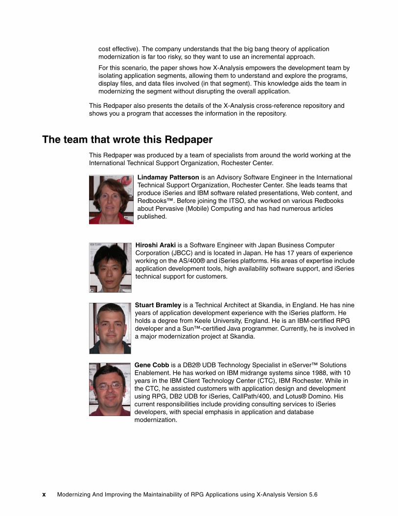
Lindamay Patterson is an Advisory Software Engineer in the International Technical Support Organization, Rochester Center. She leads teams that produce iSeries and IBM software related presentations, Web content, and Redbooks™. Before joining the ITSO, she worked on various Redbooks about Pervasive (Mobile) Computing and has had numerous articles published.
Hiroshi Araki is a Software Engineer with Japan Business Computer Corporation (JBCC) and is located in Japan. He has 17 years of experience working on the AS/400® and iSeries platforms. His areas of expertise include application development tools, high availability software support, and iSeries technical support for customers.
Stuart Bramley is a Technical Architect at Skandia, in England. He has nine years of application development experience with the iSeries platform. He holds a degree from Keele University, England. He is an IBM-certified RPG developer and a Sun™-certified Java programmer. Currently, he is involved in a major modernization project at Skandia.
Gene Cobb is a DB2® UDB Technology Specialist in eServer™ Solutions Enablement. He has worked on IBM midrange systems since 1988, with 10 years in the IBM Client Technology Center (CTC), IBM Rochester. While in the CTC, he assisted customers with application design and development using RPG, DB2 UDB for iSeries, CallPath/400, and Lotus® Domino. His current responsibilities include providing consulting services to iSeries developers, with special emphasis in application and database modernization.
x Modernizing And Improving the Maintainability of RPG Applications using X-Analysis Version 5.6

Joel Eikenhorst is a Senior Software Engineer with the Client Technology Center in IBM Rochester, Minnesota. He has 28 years of experience in various areas of the Rochester Lab including: Data Communications, Client/Server Technologies, VMC-SLIC, Database, Performance Analysis, and Java. His current interests include program modernization, development tools, and rich client technologies. He holds an M.S. degree in Computer Science from the University of Nebraska.
Stuart Milligan is the Technical Marketing Manager at Databorough and is responsible for the technical design and development of X-Analysis modernization extensions. He has been involved in AS/400 and iSeries modernization projects for more than 10 years. He leads the modernization of a COBOL36 and RPG II application named Macro 2000, which he originally co-wrote in the early 1990s. He has a substantial amount of iSeries project experience, working on projects around the world.
James Simons is a Senior Technical Consultant with the Genelco Software Services Division of IBM. He is currently focusing on application modernization. For the past 20 years, he has specialized in developing business and technical solutions for the life insurance industry. He holds several professional insurance industry designations. He has held a variety of technical roles relating to application development including business analyst, technical analyst, developer, project manager, project team leader, director of information services, and head of business operations. He has developed and supported RPG applications for the IBM iSeries platform and all of its
predecessors back to the System/34. He has additional development and implementation experience in personal computers, client/server, and Web applications written in Visual Basic®, C++, and Java. He holds a Computer Science degree from Purdue University.
Mark Tregear is a co-founder of Databorough and a lead designer of X-Analysis and its extensions. He has worked on X-Analysis development for the past 15 years and on the AS/400 since its launch. Mark graduated from Cambridge University in Economics. He started work as an RPG programmer on the System 38 in 1981, specializing in financial applications. Currently, he works at the Databorough development center in Weybridge, England.
Thanks to the following people for their contributions to this project:
Mark RinkerFastLeap, US
Juan Jorge Stromsdorfer B.I.P.M.-G.S., Columbia
Mike SmithIBM Systems and Technology Group, Development, Rochester
Jim DiephuisIBM Systems and Technology Group, On Demand Business, Rochester
Greg HurlebausCheryl RennerIBM Systems and Technology Group, Operations eServer Solution Enablement, Rochester
Preface xi
Alison ButterillGarry KipferIBM Sales & Distribution, Operations, Markham, ON
Become a published authorJoin us for a two- to six-week residency program! Help write an IBM Redbook dealing with specific products or solutions, while getting hands-on experience with leading-edge technologies. You’ll team with IBM technical professionals, Business Partners, and/or customers.
Your efforts will help increase product acceptance and customer satisfaction. As a bonus, you’ll develop a network of contacts in IBM development labs, and increase your productivity and marketability.
Find out more about the residency program, browse the residency index, and apply online at::
ibm.com/redbooks/residencies.html
Comments welcomeYour comments are important to us!
We want our papers to be as helpful as possible. Send us your comments about this Redpaper or other Redbooks in one of the following ways:
� Use the online Contact us review redbook form found at:
ibm.com/redbooks
� Send your comments in an e-mail to:
� Mail your comments to:
IBM Corporation, International Technical Support OrganizationDept. JLU Building 107-23605 Highway 52NRochester, Minnesota 55901-7829
xii Modernizing And Improving the Maintainability of RPG Applications using X-Analysis Version 5.6
Chapter 1. Overview: modernization and X-Analysis
This chapter discusses the basic rationale for modernization, introduces X-Analysis, and presents different modernization scenarios. The chapter introduces the Model-View-Controller architecture, one of the end products produced in the modernization scenarios.
This chapter presents the iSeries Developer Roadmap and explains how X-Analysis fits into the roadmap.
1
© Copyright IBM Corp. 2006. All rights reserved. 1

1.1 Why modernize an existing application?Each company has its own set of reasons for modernizing its applications. Companies do not modernize their applications just to catch the next technology wave. Rather, they are driven by specific business needs, such as:
� Improving application accessibility through open interfaces — The style that companies operate in has changed over the years. Frequently, companies make their core applications accessible to their business partners, customers, and remote workers. Often this access is given via a browser-based interface to the core applications.
� Improving the responsiveness of development — Rapidly changing business needs require development of additional functionality with minimal risk of disrupting applications already in production.
� Improving long-term maintainability — The majority of an application’s life is spent in application maintenance. To increase the longevity and decrease maintenance cost, business applications must be refactored to handle change easily.
� Improving portability of applications across platforms — Companies want the flexibility to run their applications on a diverse set of platforms. Applications written in modern programming languages give companies the flexibility to select from a variety of platforms.
� Increasing the ability to attract developers skilled in the new languages — The great majority of newly qualified application developers are skilled in languages other than RPG and COBOL. Requiring new recruits to retrain in the traditional languages is an additional expense and unappealing to the new developers. Finding skilled developers becomes less of a problem when the companies move to the new programming techniques and languages.
� Increasing number of tool options and application packages — The Java and Open Source communities encourage a very competitive software vendor market that supplies tools, techniques, and solutions to companies. Companies can take advantage of these items to improve their application development.
Whatever the business needs driving companies to modernize their applications, they want to ensure that the business logic, a core asset to the company, is preserved. They also want to minimize the pain and effort required to modernize their applications. The following chapters show you how to do just that.
1.1.1 Modern application considerationsPreviously, we discussed the main reasons for modernization from a business-need standpoint. Table 1-1 compares traditional applications and modern applications.
Table 1-1 Modern versus traditional applications
Application characteristic Modern application Traditional application
Structure Modular, reusable, component based
Monolithic, intertwined, repetitive code across programs
Componentization Functionally cohesive Arbitrary
User Interface Multiple 5250
Flexibility Diverse platforms iSeries and its predecessors
2 Modernizing And Improving the Maintainability of RPG Applications using X-Analysis Version 5.6

Application structure RPG and COBOL programs are traditionally implemented in a single-source member. All screen input/output (I/O), file I/O, and business logic are intertwined in a single large module. Enhancing these applications is difficult because the screen I/O, file I/O, and business logic are conjoined. Adding a new user interface such as a browser interface is much more complex in this instance. Contrast this with a program where the business logic has been separated into reusable components that can be used by many programs. This approach allows you to retain the 5250 user interface program that calls the business logic and have a Web-based front end that is using the same business logic.
Modular programs separate the database access from the business logic. For example, instead of directly accessing a payroll file from several programs. Separate procedures provide the database access functions, making it easier to add a field to a table. You make the change in one place instead of modifying every program that accesses that table.
In the past, the business logic was copied into several programs. If the business logic needed to change, each program with the business logic had to be changed. Moving to modern applications where the business logic is isolated into its own separate callable procedure allows any changes to the business logic to be limited to a single module.
ComponentizationMonolithic programs are difficult to maintain, becoming brittle over time. For example, a change to the business logic can have unexpected side effects.
Moving from monolithic programs to a component-based architecture requires more than just subdividing the programs. Building an effective component-based architecture requires a design that ensures separation of the application into functionally cohesive modules. The essential feature of these modules must be that the input and output parameters are clearly defined and understood in all possible circumstances. It also requires adherence to good naming conventions for the data files and fields, so that all module interfaces are clearly documented.
User interfaceTraditional applications often support only a 5250 user interface.
A modern application needs, at a minimum, to support a browser-based user interface for use both in-house and over the Web. It is also desirable to support other interfaces such as rich client and traditional 5250 data entry screens.
FlexibilityThe traditional application is written to run in the same context. It is implemented to support a specific user interface and context and does not easily integrate with other components.
A modern application is made up of components that can be used in different contexts. They can be deployed on different servers, can be used with different user interfaces and can be integrated with other components.
Chapter 1. Overview: modernization and X-Analysis 3

1.2 Architecture a modern applicationThe key to modernizing an application is to use the right application architecture. The recommended architecture is multi-tiered and based on the Model-View-Controller (MVC) architecture:
� Model is the combined business logic and the data.� View is the user interface component.� Controller controls the interactions between the view and the model. It recognizes user
interface events.
Figure 1-1 depicts the MVC architecture and its relationship to a three-tier architecture. The three tiers are the presentation layer (representing the view and controller), the (business) logic layer, and the data layer. The Model contains the business logic and the database.
Figure 1-1 MVC and multi-tier architecture
The reason why this architecture is popular is its flexibility. Figure 1-2 on page 5 gives two representations of a multi-tier application. In one scenario (Web Browser User Interface) the view-controller is implemented using a browser and JavaServer Faces (JSF) interacting with an application server. The business logic is in RPG accessing the data layer using Structured Query Language (SQL). The second architecture (Rich Client User Interface) lets you deploy individual components on different systems. The application server could run on one system and invoke the RPG business logic running on another system while the database is located on a third system.
There are two reasons you might want to do this:
� Scalability — At the application server or the business logic tier, enabling you to deploy multiple instances of a component on different systems.
� Security — A firewall can be placed between each component. This ensures that users have controlled access to business logic and the data.
View
Presentation
View - Controller
Database
Logic Data
Model
Controller BusinessRules
Tier
4 Modernizing And Improving the Maintainability of RPG Applications using X-Analysis Version 5.6

Figure 1-2 Application tiers
1.2.1 Using stateless programsTraditional 5250 application programs interact directly with the user. The user selects an option from the menu, and a screen is presented. When the user enters data into the screen, the data is stored in a variable. The application holds this data until the program ends. This data is held, even if the user performs additional interactions with the program. This approach works because the program is running in a job associated with a workstation and that job only services requests from that workstation. In this environment, the program state is maintained in variables that are associated with the job.
Contrast this with a browser-based application where each request from the user can be serviced by a different job. In this case the information the user entered cannot be kept in program variables because the next time the user interacts with the application, the application may be running in a different job.
Figure 1-3 on page 6 shows both an existing application and a (modernized) browser-based application. In the traditional application you see each user is tied to a job. This architecture works well with a limited number of users and can scale to support several hundred users by adding memory and processors to a system. However, a Web application must support several thousand users, so it is not practical to have each user connected to a job. Instead, the modern application environment has services that do not rely on state information being stored in program variables. Any required state information is passed through parameters or the context is retrieved based on the values.
Database
Tier 4
LAN
Tier 3
Tier 2
Tier 1
Tier 3
Tier 2
Tier 1
Web Browser User Interface Rich Client User Interface
RPG Program(Business Logic)
Data Access Layer
Web ApplicationServer
Web Server
Database
RPG Program(Business Logic)
Data Access Layer
Rich ClientApplication Server
Browser Browser RCP RCP
Note: A key point to remember is that a browser-based application may have state information but the state is not kept in the program variables. It may be kept in a cookie and transmitted with each request.
Chapter 1. Overview: modernization and X-Analysis 5

Figure 1-3 Applications environments
1.3 Service-oriented architectureThe long-term goal of modernization is to move to a service-oriented architecture (SOA). SOA is an integration architecture based on the concept of a service. The business and infrastructure functions that are required to build distributed systems are provided as services that individually or collectively deliver application functionality to applications or other services.
Services are the building blocks to SOA, which provide the function for building distributed systems. Services can be invoked independently by either external or internal service consumers. A service can process simple functions or can be chained with other services to form more complex functionality and to quickly devise new functionality.
By adopting an SOA approach and implementing it using supporting technologies, you can build flexible systems that implement changing business processes quickly. This approach enables you to make extensive use of reusable components.
For additional information about SOA refer to Managing Information Access to an Enterprise Information System Using J2EE and Services Oriented Architecture, SG24-6371.
Modernized Application Environment
Existing Application Environment
…
Application Server
…
Job 1 Job 2
User1 User2
(Job 3)(Job 2)
BusinessLogic(Job 1)
User1 User2 UserN
6 Modernizing And Improving the Maintainability of RPG Applications using X-Analysis Version 5.6

1.4 General principles for automated modernization projectsIn many cases, implementing and administering any automated application conversion process can be a complex and daunting task. Consider these situations:
� Applications rarely remain static, making it difficult to establish a baseline for implementing and testing the potentially enormous number of application changes.
� Various programming teams within an organization may be working simultaneously on multiple versions of the applications. Each team may have a different task:
– One team is developing the next release of the application.
– The test team has another version of the application in quality assurance.
– The maintenance team is fixing recently reported problems to the production version.
� Frequently, software vendors have different versions of an application to support different customer needs.
Modernization changes should be applied to most or all versions of your applications and products, in all stages of the development life cycle. The effort to apply, test, and promote these modified versions of the applications can be traumatic. Each version of the application generates a new version containing the conversion changes. All development must stop while the converted versions of the applications are tested, refined, and promoted to production. The number of application versions may balloon because of unsuccessful attempts coupled with schedule and budget constraints. This situation creates more maintenance and version control activity, increasing the amount of time and resources required to complete the conversion.
Is it possible to actually get your arms around the effort and carry out the modernization process? Yes, but a sound approach is the key to your success. The following steps outline a recommended and simplified approach that you may want to consider:
1. Clearly delineate the application boundaries to be converted.
2. Copy all delineated objects and source code to a separate library (or set of libraries)
3. Recompile this target conversion library and test the resulting system. This is your control test.
4. Perform a trial conversion process without attempting to freeze the code or administer change management. Significant conversion errors are expected at this stage.
5. The conversion process can be fine-tuned by a mixture of:
– Improving the quality of the original code
– Changing conversion parameters
– Enhancing the conversion software you are using. This may require enhancement to particular software conversion routines.
6. Thoroughly document any manual intervention required in the conversion process, to ensure that the process is repeatable.
7. Iterate through the conversion process enough times to successfully pass all tests to your satisfaction. You are now ready for the live production conversion.
8. Freeze development on the delineated application completely for several days (for the duration of the production conversion).
9. Perform the conversion from beginning to end and perform a rapid acceptance test.
10.Use your normal change management procedures to place the converted application into the production source and object libraries.
Chapter 1. Overview: modernization and X-Analysis 7

1.5 Introducing X-AnalysisX-Analysis is an integrated development environment (IDE) used to analyze and enhance existing applications written in RPG, COBOL, Java, and Visual Basic. X-Analysis generates and uses a cross-reference repository, process model, and data model based on the existing application. The repository and the models are the input to X-Analysis’s comprehensive cross-referencing, documentation, and re-engineering facilities. The X-Analysis client is used to graphically view, explore, and extract components from these models. A development team can use the X-Analysis client to visually analyze the overall model of an application and to drill down to the precise details of the existing program code.
Figure 1-4 presents the architecture of X-Analysis. The product includes both server-side and client-side components. The cross-reference repository, process model, and data model are built with X-Analysis commands issued on the server. X-Analysis uses all aspects of an application (source codes, display files, and database file) to generate the repository and models. After the repository and models are built, the developer can graphically view and access them using the X-Analysis client.
The X-Analysis client can be used to re-engineer an existing RPG application to an MVC architecture. The X-Analysis client generates JavaServer Faces for the existing user interface, JavaBeans for the user interface handling, and stored procedures to interact with the database. X-Analysis can produce standard functions representing idealized logical screens for searching and updating the application. X-Analysis includes abstract Java classes to support this component-based architecture.
Figure 1-4 X-Analysis structure
X-Analysis can also be used to generate a partial model of the application (known as an application area). Generating a partial model is performed using X-Analysis to subdivide the application into areas based on an interrelated set of files, programs, or both. Typically an application area is used when the goal is to modernize a subset of the existing application.
iSeries
Personal Computer
Existing Application
RPG Code Database
DisplayFiles
X-AnalysisInitializationCommands
X-Analysis(client)
Cross Reference Repository• Data Model• Process Model• Application (sub division)
JSFs JavaBeans
StoredProcedures
X-AnalysisReengineering Process
Invoke
AbstractJavaClasses
8 Modernizing And Improving the Maintainability of RPG Applications using X-Analysis Version 5.6

X-Analysis benefits companies with large existing applications with any of the following characteristics:
� Lack understanding of the application requiring enhancements.
� Must quantify and plan the impact of proposed design modifications.
� Must improve their data integrity.
� Must improve the testing process for existing or modernized applications.
� Need to recover the implicit data model and extracted business rules.
� Require a new user interface to interact with existing business rule logic without rewriting the existing application.
1.5.1 X-Analysis componentsX-Analysis consists of a foundation product and various extensions that can be installed as needed by the customer. Figure 1-5 shows the X-Analysis product with various extensions and how they fit together.
Figure 1-5 X-Analysis components
Each of the modules provide important capabilities to the development team. X-Analysis is described as follows:
� X-Analysis (foundation) provides the core cross-referencing capabilities:
� Performs application and data model generation.
� Provides cross-referencing with drilldown to specific details (variables, fields, or lines of code).
� Enables interactive viewing of source code, application structure diagrams, and data flow diagrams.
� Gives a graphical view of all aspects of the existing application and the object where used.
� X-Rev reverse engineers higher-level modeling information not directly contained in the existing code:
– Extracts the data model implicit in the existing application.
– Generates a data encyclopedia or data dictionary.
– Aids data field analysis.
– Documents data entity relationships.
Note: X-Browse interacts with X-Subset, X-Verify, and X-Archive, and they are often purchased together.
X-Analysis(foundation)
X-Rev
X-BrowseX-SubsetX-Verify
X-ArchiveX-Resize X-Control
X-Extract
X-MigrateApplicationOverview
Chapter 1. Overview: modernization and X-Analysis 9

� Application Overview (usually accompanies X-Rev) provides comprehensive documentation and application subdivision capabilities:
– Subdivides the application as needed based on the models.
– Presents RPG code as pseudo code.
– Documents business rule logic.
– Provides Microsoft® Word and Visio® documentation wizards.
– Enables viewing model subsets.
– Provides export and source configuration management software tools.
� X-Browse enables you to view and navigate your database using the extracted data model:
– Provides instant query and report applications (without programming).
– Creates joins for related data files.
– Provides drilldown links to all dependant data files.
– Optimizes application performance using existing logical views.
– Identifies available access paths and views.
– Provides a completely formatted display of OS/400® journals for application data.
� X-Subset, X-Verify and X-Archive aid in application testing and data archiving:
– X-Subset builds a referentially consistent test data set for application testing.
– X-Verify enables the testing of the referential integrity of production data based on the data model.
– X-Archive handles selected or complete data archiving with selection criteria and audit trails. It also ensures that referential integrity is maintained in the remaining data (in other words no records are orphaned).
� X-Resize provides automated data file and field re-engineering:
– Provides impact analysis for all data instances (such as fields, variables, programs, files).
– Provides exception reporting for special conditions and overlapping.
– Includes automated:
• Source conversion for all objects and source types
• Bulk recompile
• Data conversions
� X-Control provides automated and integrated change management services:
– Offers a single command request for programmer changes.
– Provides parallel machine support.
– Includes various controls and audits:
• Control of modules returned to systems (by identification)
• Audit history
• Archiving of source and object code
– Interfaces to documentation in Microsoft Office or text files.
� X-Extract identifies and expresses business rule logic from individual programs or parts of the system:
– Extracts a comprehensive database of business rules implicit in the existing code.
10 Modernizing And Improving the Maintainability of RPG Applications using X-Analysis Version 5.6

– Provides narrative documentation of each extracted business rule, enabling them to be viewed either stand alone or in the context of the programs from which they have been extracted.
– Generates a complete Data Definition Language from the data model.
– Generates XML Metadata Interchange (XMI) format from the model.
� X-Migrate deconstructs the existing application into new components, which can then be deployed in modern environments (such as a Web server environment)
– Generates data access objects for use with modern user interfaces.
– Generates a generic controller following Model-View-Controller architecture.
– Generates stateless business rule components from the RPG applications.
1.6 X-Analysis and the iSeries Developer RoadmapAs new technology comes along, existing programming languages and related programming models change to incorporate and take advantage of these advancements. The iSeries Developer Roadmap, created by IBM, shows how companies with traditional 5250 applications can evolve those applications to incorporate the new programming languages and methodologies. The roadmap as shown in Figure 1-6 consists of six pillars. Each pillar identifies a modernization goal and the programming languages and technology associated with that pillar. The six pillars are:
� Traditional
Existing RPG or COBOL applications with a 5250 user interface. The applications frequently rely on a programming model where all aspects of the application are included in a single module, making the application hard to maintain and change.
� Improve your productivity
The use of technology and tools to maintain existing applications without unnecessary change.
� Enhance the end user experience
Restructuring the presentation layer of the application, making it suitable for use with graphical and browser interfaces.
� Create a modular architecture
An application is redesigned to take advantage of new programming models, such as the Model-View-Controller architecture. An objective of this phase is to separate the various aspects of the application into reusable components.
� Integrate applications
As business needs change, companies create or purchase new applications. These applications are frequently written in new programming languages. It is important that the existing applications and new applications can share data.
� Integrate business processes
Businesses must react quickly to change. Business processes can be affected by these changes. As business processes change, the applications that support them must change as well. The goal of this pillar is to incorporate technology that enables all aspects of the business to react quickly to change.
Aligning your business applications with any of the pillars can cause improvements to your business and development environment. It is important to evaluate your business needs to understand the form of modernization that is right for your company.
Chapter 1. Overview: modernization and X-Analysis 11

Figure 1-6 iSeries Developer Roadmap (technology view)
1.6.1 Future tools view of the iSeries Developer RoadmapIn order to realize the benefits of the iSeries Developer Roadmap, IBM through its IBM eServer iSeries Initiative for Innovation program has developed a corresponding future tools view of the roadmap (Figure 1-7 on page 13). This view identifies tools and technology that enhance your application modernization effort. Both IBM and Business Partner tools and technology are included in this roadmap.
Enhance theEnd User
Experience
Create aModular
Architecture
IntegrateApplications
IntegrateBusiness
Processes
ImproveYour
ProductivityTraditional
RPG/COBOL
52505250
RPG/COBOLILE and Java
HTML/JSP
DB2 and SQL
Connectors Process Choreography
DB2 and SQL
RPG/COBOL
XML XML
Portlets
GUI GUI5250GUI
ILE/Java
Java/EJB
ILE (e.g. RPG, COBOL, …)
GUI
Application Technology
User Interface
Portlets
HTML/JSP HTML/JSPHTML/JSP
5250 5250
Servlets ServletsServletsServlets
Portlets Portlets
XML XML
DB2 and SQL
Web Services Web Services
PDM
5250
12 Modernizing And Improving the Maintainability of RPG Applications using X-Analysis Version 5.6

Figure 1-7 iSeries Developer Roadmap - Future Tools View
1.6.2 X-Analysis and the roadmapX-Analysis provides capabilities that fit within the first three pillars shown in Figure 1-7. The pillars are mapped to X-Analysis as follows:
� Improve your productivity: X-Analysis’s primary function is to improve the productivity of the application development team. It accomplishes this through a rich set of documentation and navigation capabilities. X-Analysis allows developers quick access to cross-referencing functions, graphical structure displays, and process flow information. The existing applications’ implicit data model and business rules can be extracted. Development teams can use X-Analysis to understand and maintain their current RPG and COBOL applications.
� Enhance the end user experience: X-Analysis provides the capabilities that enable a business to improve the application user interface and increase the flexibility of applications. X-Analysis extensions provide the means to generate JavaServer Faces (JSF) and JavaBeans, which provide a new user interface for the existing application.
� Create a modular architecture - X-Analysis assists in recovering design information necessary to re-engineer selected application areas and to prepare the move to a component-based architecture such as MVC architecture. In order to accomplish this transformation, application programmers and analysts need a deep understanding of their business logic and data model. X-Analysis dynamically extracts the data model and process model specific to each application area. The developers can then drill down into the detail of the business rule logic involved. Developers find the cross-referencing and documentation functions extremely helpful when creating a new component-based architecture.
Improve Your Productivity
Backup /Recovery
Code Analysis(Documentation)
DatabaseEditor & Viewer
Education Tools
Migration, Conversion of Legacy
IDE
Operations
Availability
iSeries SoftwareDistribution
Enhance the End User
Experience
ApplicationServers
Domino Servers
Portal &Personalization
Online AnalyticalProcessing
Application Refacing
PredictiveAnalytics
IntegrateApplications
Barcode’Forms’RFD
Connectivity
Data Movement &Migration
Payment Servers
ETL/dataWarehouse
EAI ApplicationIntegration
Wireless
Mail / Messaging
Integrate BusinessProcesses
EDI / XML
FAX
ProgrammableLogic Controller
Content ImageManagement
Telephony
BusinessIntegration
e-commerce
Create aModular
Architecture
Business RuleLogic Ext. for SDN
Client Integration
.NET Integration
Performance /Tuning
Secure yourEnterprise
Source control‘degub’lost’ deploy
Test DataManagement
Query / ReportWriting
Report & DataDelivery
Regenerate RPGinto J2EE
RP3 to JavaConversion
UCCNET
Workflow
Chapter 1. Overview: modernization and X-Analysis 13
1.7 X-Analysis modernization scenariosAs stated previously, X-Analysis plays an important role in application modernization. This section identifies three business scenarios and suggests the paths available to modernization.
1.7.1 Business scenario 1The first scenario introduces a software vendor with many years of RPG programming experience and some Java and Web development skills. They have a large application with too many programs to consider converting them by hand. The team does not know how much effort would be required to modernize the application. Most of the applications are written in Original Program Model (OPM) RPG and a few are written in Integrated Language Environment (ILE) RPG. The company faces competitive pressure to provide browser-based interfaces and rich client support.
Therefore this company has decided to totally transform the presentation and control layers of their application to the MVC architecture.
1.7.2 Business scenario 2The company in this scenario develops most of its applications in-house, using both OPM and ILE RPG. Their biggest concern is the amount of time at it takes to respond to new requests for added functionality. Often instead of trying to reuse existing programs, they create a new version of an existing program, compounding their maintenance problems. For example, in a recent project requiring the expansion of the customer number field from five digits to seven digits, they spent much more time than was budgeted. They know they must deal with these maintenance issues and find a new approach to handling enhancements. However, re-architecting the applications and using Java are not an option, at least not any time soon.
For this scenario, the customer needs clear documentation and an approach that will improve maintenance productivity without making any radical change to their applications. The company wants to take a conservative approach with minimal change and disruption while achieving improved maintenance productivity and the ability to add new function.
1.7.3 Business scenario 3This company has highly skilled RPG and Java developers on staff, doing sophisticated iSeries and Web development. The application suite of RPG programs has grown over the years in an ad hoc manner. The RPG applications were developed quickly to respond to business opportunities with little thought of how they would be maintained or enhanced as business conditions changed. The company now has a large number of complex applications that are difficult to enhance, which prevents them from responding to business opportunities quickly. The IT executive and staff decided that future projects will be developed using modern methodologies when possible. They will write Java components when appropriate, rework the RPG code to components as necessary, or port the RPG code to Java when the effort to rework the RPG code is too expensive.
The executive wants to modernize the applications incrementally. He knows that converting all of the applications at one time would be a disaster. The company is looking for a method to help the staff isolate application areas, recover the business logic and the data model from the existing application, and re-engineer the application where possible.
This company is typical of situations where modernization occurs on an application section by section basis. One section of the application is rebuilt at a time, but when each section is rebuilt, a thorough modernization is required.
14 Modernizing And Improving the Maintainability of RPG Applications using X-Analysis Version 5.6

Chapter 2. Introducing the sample application
This chapter discusses the sample application used in this paper. The sample application represents a typical existing RPG application targeted for modernization. A typical application resides in a library containing both the production application modules and extraneous source code, objects and data files that are no longer used. The extra items are not part of the production application but are still in the library for a variety of reasons.
The chapter first explains the Customer Management System and lists the additional files and programs in the application library.
2
© Copyright IBM Corp. 2006. All rights reserved. 15
2.1 About the sample applicationIn order to show the capabilities of X-Analysis, we are using the sample application library (XRAPPS), which contains the Customer Management System (CMS) application and related data files, along with additional RPG programs, display files, and data files. These additional files are included to demonstrate the ability of X-Analysis to delimit application areas that are targeted for application modernization. In the subsequent chapters, you see how X-Analysis can make sense of a typical application library and how to recover a particular subset of a larger application.
It is a common situation for existing application libraries to contain extraneous content such as program copies, obsolete programs, test programs, versions of programs, and unused data files. This situation often occurs as business applications evolve and are enhanced over a number of years. By adding extra programs and data files to the CMS library (XRAPPS), we simulate this condition.
The contents of the XRAPPS library are presented in two steps:
1. The CMS application is discussed.2. The additional data files and programs in the XRAPPS library are listed.
2.2 Overview of the Customer Management SystemThe Customer Management System (CMS) (in this paper) is a version of the RPG application used by Databorough to manage their customer and contact information and related details. This application was developed by Databorough for their own use. They have been using the application for a number of years and over time it has been enhanced and extended to meet changing business needs.
Databorough has distributors that support specific territories around the world. Each distributor has salespersons who promote the product through contacts at prospective customer sites. The customers who purchase the product sign maintenance contracts at which time the customer is given a unique security code. The CMS application is used by the sales organization and distributors to maintain customer relationship information such as customer, contact, and contract information.
2.2.1 Customers Main MenuCMS is started using these steps:
1. Add the application library to the iSeries library list. Enter:
addlible XRAPPS
2. To start the application on the iSeries, enter:
go XCMMENU
When the application is invoked, the Customers Main Menu (Figure 2-1 on page 17) enables the distributors and sales people to access and maintain the customer-related information.
16 Modernizing And Improving the Maintainability of RPG Applications using X-Analysis Version 5.6

Figure 2-1 Customers Main Menu
The programs associated with the main menu are:
� Customers Main Menu (XCMMENU)� Customer Site Maintenance (CUSFMAINTC)� Organization Maintenance (ORGMNT)� Account Update (CUS002)� Work with Customer Contacts (WWCCONSC)� Work with Customer Sites (WWCUSF)� Work with Rep. Delivery Areas (WWRAREASC)
Customers M A I N M E N U Databorough Ltd. XCMMENU 15:37:22 9/16/05 Select one of the following: 1. Customer Site Maintenance 2. Organisation Maintenance 3. Account Maintenance 4. Work with Customer Contacts 5. Work with Customer Sites 6. Work with Rep. Delivery Areas
Selection or command ===> F3=Exit F4=Prompt F9=Retrieve F12=Cancel F13=Information Assistant F16=AS/400 main menu
Chapter 2. Introducing the sample application 17

Option 1: Customer Site MaintenanceFigure 2-2 shows the Customer Site Maintenance screen flow and lists the screens associated with this option.
Figure 2-2 Customer site maintenance flow
WWRAREASWork with Rep. Delivery Areas
WWRAREASCWork with Customer Contacts
Option 1 Customer Site Maintenance
Option 5 = Display
F8 = Contacts
F9 = Distributor
F10 = Del. Areas
Customer List(pop up)
WWRAREASWork with Rep. Delivery Areas(detail)
CUSFMAINTCustomer Site Maintenance
WWCCONSWork with Customer Contacts
WWCCONSWork with Customer Contacts(detail)
DSPDISTSDistributor Display
Select one
Option 5 = Display
18 Modernizing And Improving the Maintainability of RPG Applications using X-Analysis Version 5.6

When option 1 is selected from the Customers Main Menu, the customer list (Figure 2-3) is displayed. To work with a particular customer, select that customer from the list.
Figure 2-3 Customer list
When a customer is selected, in this case Bertwhistle & Company Ltd., the Customer Site Maintenance screen appears (Figure 2-4).
Figure 2-4 Customer Detail (select one)
Customers M A I N M E N U Databorough Ltd. XCMMENU 15:46:00 9/16/05 Select one of the following: Please select: 00001 Bertwhistle & Compan 00002 Turpin Computers 00004 Teflon Company of G. 00005 Turbine Components L 00006 Gough Research plc 00009 Newt Foods UK Ltd. 00014 Bock & Co. Ltd 00015 Besson Bros. 00017 Media Enterprises Lt 00018 Bays Engineering Lt + Selec ===> 1 F3=Exit F4=Prompt F9=Retrieve F12=Cancel F13=Information Assistant F16=AS/400 main menu
Customers Customer Site Maintenance Databorough Ltd. CUSFMAINT 15:48:42 16 Sep 2005 Customer No . . . . . . . 00001 Customer Name . . . . . . Bertwhistle & Company Ltd Address . . . . . . . . . Harmon ross Halesowen Road Cradley Heath Warley West Midlands Country . . . . . . . . . Postcode . . . . . . . . B64 7JB Telephone No . . . . . . 0121 550 1841 Fax. No . . . . . . . . . 0121 550 753 Email Address . . . . . . [email protected] Website . . . . . . . . . www.bertco.com Distributor, Salesperson DT STU Status . . . . . . . . . 5 Contact . . . . . . . . . Janet Dawson Title . . . . . . . . . . Mrs Job Title . . . . . . . . Financial Director Last Contact Date . . . . 2003-05-14 Next Contact Date . . . . 2003-10-25 Please make required changes. (F8=Contacts,F9=Distributor,F10=Del.Areas)
Chapter 2. Introducing the sample application 19
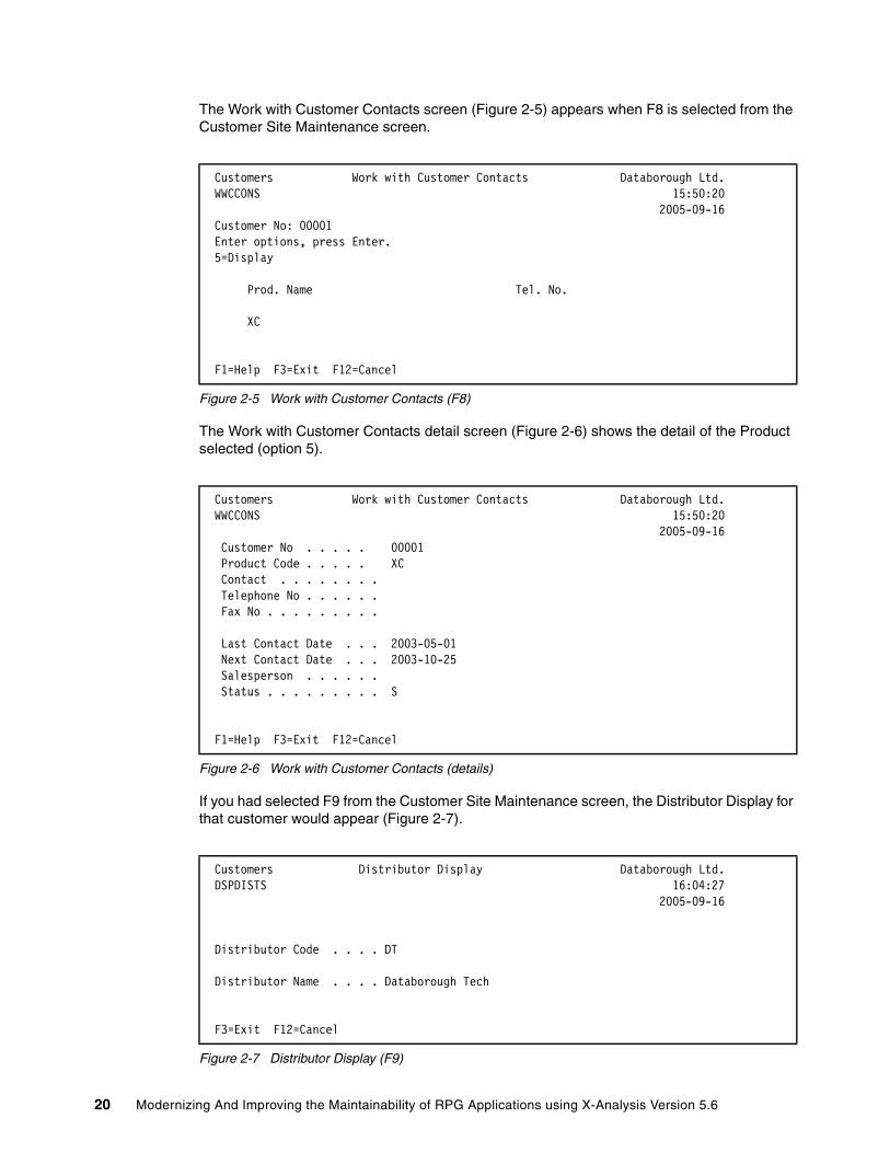
The Work with Customer Contacts screen (Figure 2-5) appears when F8 is selected from the Customer Site Maintenance screen.
Figure 2-5 Work with Customer Contacts (F8)
The Work with Customer Contacts detail screen (Figure 2-6) shows the detail of the Product selected (option 5).
Figure 2-6 Work with Customer Contacts (details)
If you had selected F9 from the Customer Site Maintenance screen, the Distributor Display for that customer would appear (Figure 2-7).
Figure 2-7 Distributor Display (F9)
Customers Work with Customer Contacts Databorough Ltd. WWCCONS 15:50:20 2005-09-16 Customer No: 00001 Enter options, press Enter. 5=Display Prod. Name Tel. No. XC
F1=Help F3=Exit F12=Cancel
Customers Work with Customer Contacts Databorough Ltd. WWCCONS 15:50:20 2005-09-16 Customer No . . . . . 00001 Product Code . . . . . XC Contact . . . . . . . . Telephone No . . . . . . Fax No . . . . . . . . . Last Contact Date . . . 2003-05-01 Next Contact Date . . . 2003-10-25 Salesperson . . . . . . Status . . . . . . . . . S
F1=Help F3=Exit F12=Cancel
Customers Distributor Display Databorough Ltd. DSPDISTS 16:04:27 2005-09-16 Distributor Code . . . . DT Distributor Name . . . . Databorough Tech
F3=Exit F12=Cancel
20 Modernizing And Improving the Maintainability of RPG Applications using X-Analysis Version 5.6
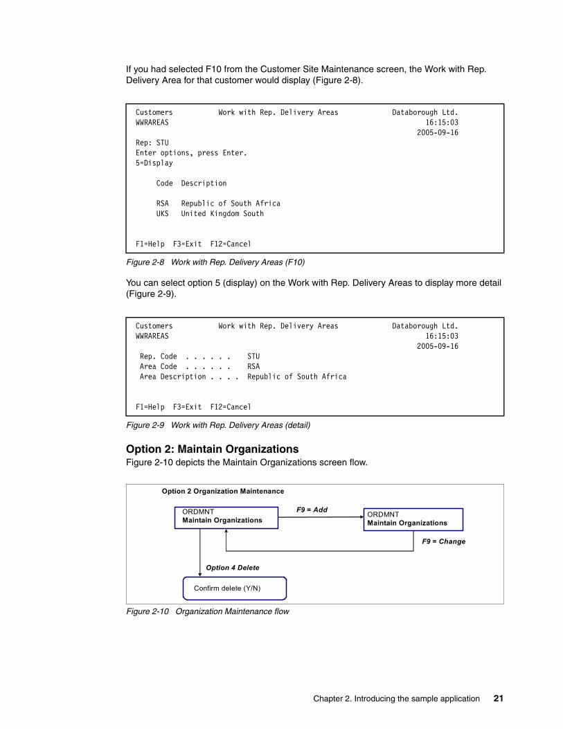
If you had selected F10 from the Customer Site Maintenance screen, the Work with Rep. Delivery Area for that customer would display (Figure 2-8).
Figure 2-8 Work with Rep. Delivery Areas (F10)
You can select option 5 (display) on the Work with Rep. Delivery Areas to display more detail (Figure 2-9).
Figure 2-9 Work with Rep. Delivery Areas (detail)
Option 2: Maintain OrganizationsFigure 2-10 depicts the Maintain Organizations screen flow.
Figure 2-10 Organization Maintenance flow
Customers Work with Rep. Delivery Areas Databorough Ltd. WWRAREAS 16:15:03 2005-09-16 Rep: STU Enter options, press Enter. 5=Display Code Description RSA Republic of South Africa UKS United Kingdom South
F1=Help F3=Exit F12=Cancel
Customers Work with Rep. Delivery Areas Databorough Ltd. WWRAREAS 16:15:03 2005-09-16 Rep. Code . . . . . . STU Area Code . . . . . . RSA Area Description . . . . Republic of South Africa
F1=Help F3=Exit F12=Cancel
Option 2 Organization Maintenance
F9 = Add
Confirm delete (Y/N)
ORDMNTMaintain Organizations
Option 4 Delete
ORDMNTMaintain Organizations
F9 = Change
Chapter 2. Introducing the sample application 21

When option 2 is selected from the Customers Main Menu, Maintain Organizations (Figure 2-11) displays the organizations.
Figure 2-11 Maintain Organization Information
If you press F9 (add), you can add organizations (Figure 2-12).
Figure 2-12 Add organization information
QPADEV0006 ORGMNT Databorough Ltd. 9/16/05 CHANGE LINDAMAY Maintain Organisations 16:19:00 Org. Type options, press Enter. 4=Delete X Org. Name Created Create Updated Update by Date by Date 1 Acoustical Turbines Ltd STU 1/02/13 STU 1/02/13 2 Acorn Harvesters plc STU 1/02/13 STU 1/02/13 3 Zenith Sound Systems STU 2/08/12 STU 2/08/12 4 Databorough Ltd AMIT 5/09/15 AMIT 5/09/15
Bottom F1=Exit F9=Add
QPADEV0006 ORGMNT Databorough Ltd. 9/16/05 ADD LINDAMAY Maintain Organisations 16:22:29
Org. Name Created Create Updated Update by Date by Date 0 0/00/00 0/00/00 0 0/00/00 0/00/00 0 0/00/00 0/00/00 0 0/00/00 0/00/00 0 0/00/00 0/00/00 0 0/00/00 0/00/00 0 0/00/00 0/00/00 0 0/00/00 0/00/00 0 0/00/00 0/00/00 0 0/00/00 0/00/00 More... F1=Exit F9=Change
22 Modernizing And Improving the Maintainability of RPG Applications using X-Analysis Version 5.6

Option 3: Account MaintenanceFigure 2-13 depicts the Account Maintenance screen flow.
Figure 2-13 Account Maintenance flow
When option 3 is selected from the Customers Main Menu, the Account Maintenance screen (Figure 2-14) displays.
Figure 2-14 Account Maintenance
Press F6 (add) to reach the Account Maintenance screen in add mode (Figure 2-15).
Figure 2-15 Account Maintenance (add mode)
DATE 9/16/05 CUS002 ACCOUNT MAINTENANCE TIME 16:27 COM DIV CUST PLACE 00 000 FOR MASTER
F3=Exit F4=PROMPT F6=ADD
00 000 DATE 9/16/05 CUS002 ACCOUNT MAINTENANCE TIME 16:27 MODE: ADD NAME NUMBER 1 ADD. 1 ABBR. ADD. 2 TEL NO. 000 0000000 CITY ST FAX : 000 0000000 ZIP CODE T.NUMBER URL T.CODE 0 TERM CODE START DATE STMT Y CNT.CLASS CR. HOLDER N 30 A/C TYPE FORMAT 00 REVIEW DATE REP STMT NOTE N TAX PCT. DLRY ZONE DAYS EXCHANGE RATE INVOICE N I/C N ADD(REMIT) FIN N P/P Tck N REF. CBD N CASH N G/L NUMBER COD N PLACE FRT CHG N DISC.1% F3=EXIT F4=PROMPT F12=PREVIOUS F14=W/O INQUIRY F23=DELETE
Option 3 Account Maintenance
F6 = AddAccount Maintenance Account Maintenance(Mode: Add)
Chapter 2. Introducing the sample application 23

Option 4: Work with Customer ContactsFigure 2-16 depicts the Work with Customer Contacts screen flow.
Figure 2-16 Work with Customer Contacts flow
When option 4 is selected from the Customers Main Menu, the customer list (Figure 2-17) is displayed.
Figure 2-17 Work with Customer Contacts (customer list)
The Work with Customer Contacts (Figure 2-18 on page 25) is displayed by selecting a customer.
Customers M A I N M E N U Databorough Ltd. XCMMENU 16:31:57 9/16/05 Select one of the following: Please select: 00001 Bertwhistle & Compan 00002 Turpin Computers 00004 Teflon Company of G. 00005 Turbine Components L 00006 Gough Research plc 00009 Newt Foods UK Ltd. 00014 Bock & Co. Ltd 00015 Besson Bros. 00017 Media Enterprises Lt 00018 Bays Engineering Lt + Selec ===> 4 F3=Exit F4=Prompt F9=Retrieve F12=Cancel F13=Information Assistant F16=AS/400 main menu
Option 4 Work with Customer Contacts
Option 5 = Display
Customer List(pop up)
WWCCONSWork with Customer Contacts
WWCCONSWork with Customer Contacts(detail)
Select one
24 Modernizing And Improving the Maintainability of RPG Applications using X-Analysis Version 5.6

Figure 2-18 Work with Customer Contacts (select one)
To see the Work with Customer Contacts detail (Figure 2-19) select option 5 (beside a product name).
Figure 2-19 Work with Customer Contacts detail (Option 5)
Option 5: Work with Customer SitesFigure 2-20 on page 26 depicts the Work with Customer Sites screen flow. The Customer Site Maintenance screen options (with the blue background) are not replicated in this section because they were shown previously. The screens not repeated are:
� Work with Customer Contacts screen (F8 from the Work with Customer Sites screen) is shown in Figure 2-5 on page 20. The associated Work with Customer Contacts detail screen shown in Figure 2-6 on page 20.
� Distributors Display (F9 from the Work with Customer Sites screen) is shown in Figure 2-7 on page 20.
� Work with Rep. Delivery Areas (F10 from the Work with Customer Sites screen) is shown in Figure 2-8 on page 21. The associated Work with Rep. Delivery Areas detail screen is shown in Figure 2-9 on page 21.
Customers Work with Customer Contacts Databorough Ltd. WWCCONS 16:33:39 2005-09-16 Customer No: 00001 Enter options, press Enter. 5=Display Prod. Name Tel. No. XC
F1=Help F3=Exit F12=Cancel
Customers Work with Customer Contacts Databorough Ltd. WWCCONS 16:33:39 2005-09-16 Customer No . . . . . 00001 Product Code . . . . . XC Contact . . . . . . . . Telephone No . . . . . . Fax No . . . . . . . . . Last Contact Date . . . 2003-05-01 Next Contact Date . . . 2003-10-25 Salesperson . . . . . . Status . . . . . . . . . S
F1=Help F3=Exit F12=Cancel
Chapter 2. Introducing the sample application 25

Figure 2-20 Work with Customer Sites flow
When option 5 is selected from the Customers Main Menu, the Work with Customer Sites (Figure 2-21) is displayed.
Figure 2-21 Work with Customer Sites
Customers Work with Customer Sites Databorough Ltd. WWCUSF 16:35:53 2005-09-16 Enter options, press Enter. 2=Change 4=Delete 5=Display No. Name Tel. No. 00001 Bertwhistle & Company Ltd 0121 550 1841 00002 Turpin Computers 0170 152 4878 00004 Teflon Company of G.B. Ltd. 0191 568 8899 00005 Turbine Components Ltd 0443 250 5151 00006 Gough Research plc 0191 967 0007 00009 Newt Foods UK Ltd. 0191 272 8930 00014 Bock & Co. Ltd 0561 624 0333 00015 Besson Bros. 05673 722651 00017 Media Enterprises Ltd 0181 223 2552 00018 Bays Engineering Ltd 06794 462199 00021 Goldfish & Sons Ltd. 0561 552 4959 00026 Linhouse Limited 03498 336501 + F1=Help F3=Exit F6=Add F12=Cancel
WWCUSFWork with Customer Sites
WWCUSFWork with Customer Sites
Option 5 Work with Customer Sites
Option 2 = Change
Option 4 = Delete
Option 5 = Display
WWCCONSWork with Customer Contacts
F6 = Add
WWRAREASWork with Rep. Delivery AreasConfirm delete (Y/N)
CUSFMAINTCustomer Site Maintenance
F8 = Contacts
F9 = Distributors
F10 = Del. Areas
WWCCONSWork with Customer Contacts
Option 5 = Display
DSPDISTSDistributors Display
Option 5 = DisplayWWRAREASWork with Rep. Delivery Areas
WWCUSFWork with Customer Sites
26 Modernizing And Improving the Maintainability of RPG Applications using X-Analysis Version 5.6
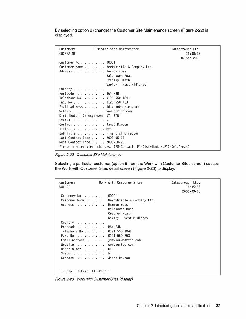
By selecting option 2 (change) the Customer Site Maintenance screen (Figure 2-22) is displayed.
Figure 2-22 Customer Site Maintenance
Selecting a particular customer (option 5 from the Work with Customer Sites screen) causes the Work with Customer Sites detail screen (Figure 2-23) to display.
Figure 2-23 Work with Customer Sites (display)
Customers Customer Site Maintenance Databorough Ltd. CUSFMAINT 16:38:13 16 Sep 2005 Customer No . . . . . . . 00001 Customer Name . . . . . . Bertwhistle & Company Ltd Address . . . . . . . . . Harmon ross Halesowen Road Cradley Heath Warley West Midlands Country . . . . . . . . . Postcode . . . . . . . . B64 7JB Telephone No . . . . . . 0121 550 1841 Fax. No . . . . . . . . . 0121 550 753 Email Address . . . . . . [email protected] Website . . . . . . . . . www.bertco.com Distributor, Salesperson DT STU Status . . . . . . . . . 5 Contact . . . . . . . . . Janet Dawson Title . . . . . . . . . . Mrs Job Title . . . . . . . . Financial Director Last Contact Date . . . . 2003-05-14 Next Contact Date . . . . 2003-10-25 Please make required changes. (F8=Contacts,F9=Distributor,F10=Del.Areas)
Customers Work with Customer Sites Databorough Ltd. WWCUSF 16:35:53 2005-09-16 Customer No . . . . . 00001 Customer Name . . . . Bertwhistle & Company Ltd Address . . . . . . . . Harmon ross Halesowen Road Cradley Heath Warley West Midlands Country . . . . . . . . Postcode . . . . . . . . B64 7JB Telephone No . . . . . . 0121 550 1841 Fax. No . . . . . . . . 0121 550 753 Email Address . . . . . [email protected] Website . . . . . . . . www.bertco.com Distributor. . . . . . . DT Status . . . . . . . . . 5 Contact . . . . . . . . Janet Dawson
F1=Help F3=Exit F12=Cancel
Chapter 2. Introducing the sample application 27
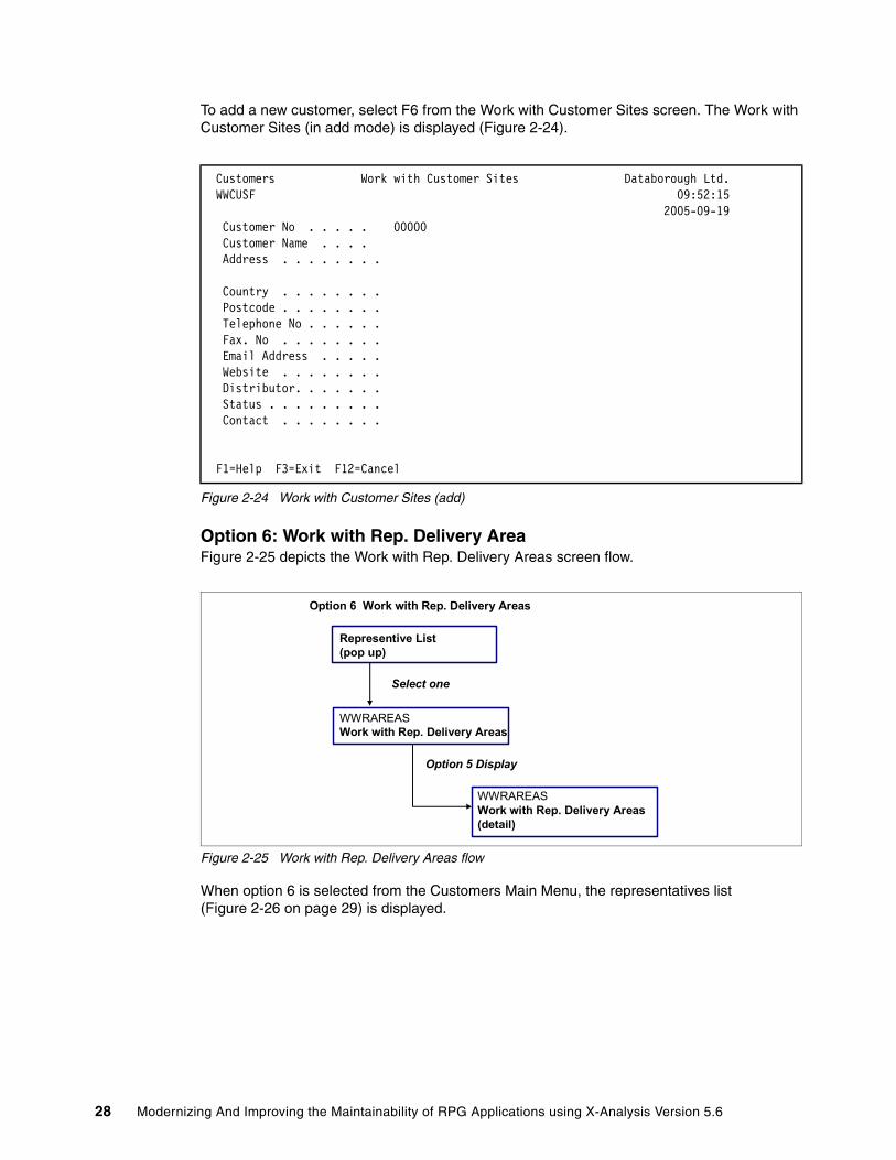
To add a new customer, select F6 from the Work with Customer Sites screen. The Work with Customer Sites (in add mode) is displayed (Figure 2-24).
Figure 2-24 Work with Customer Sites (add)
Option 6: Work with Rep. Delivery AreaFigure 2-25 depicts the Work with Rep. Delivery Areas screen flow.
Figure 2-25 Work with Rep. Delivery Areas flow
When option 6 is selected from the Customers Main Menu, the representatives list (Figure 2-26 on page 29) is displayed.
Customers Work with Customer Sites Databorough Ltd. WWCUSF 09:52:15 2005-09-19 Customer No . . . . . 00000 Customer Name . . . . Address . . . . . . . .
Country . . . . . . . . Postcode . . . . . . . . Telephone No . . . . . . Fax. No . . . . . . . . Email Address . . . . . Website . . . . . . . . Distributor. . . . . . . Status . . . . . . . . . Contact . . . . . . . .
F1=Help F3=Exit F12=Cancel
Option 6 Work with Rep. Delivery Areas
Option 5 Display
Representive List(pop up)
WWRAREASWork with Rep. Delivery Areas
Select one
WWRAREASWork with Rep. Delivery Areas(detail)
28 Modernizing And Improving the Maintainability of RPG Applications using X-Analysis Version 5.6

Figure 2-26 Delivery area list
After a particular representative is selected, the Work with Rep. Delivery Area (Figure 2-27) is displayed.
Figure 2-27 Work with Rep. Delivery Areas (select one)
When a delivery area is selected, the Work with Rep. Delivery Area detail (for the representative) is displayed (Figure 2-28).
Figure 2-28 Work with Rep. Delivery Areas (display)
Customers M A I N M E N U Databorough Ltd. XCMMENU 16:48:00 9/16/05 Select one of the following: Please select: JKL Johan Klaassen MTT Mark Tregear NWD Neil Woodhams STU Stuart Milligan
Selec ===> 6 F3=Exit F4=Prompt F9=Retrieve F12=Cancel F13=Information Assistant F16=AS/400 main menu
Customers Work with Rep. Delivery Areas Databorough Ltd. WWRAREAS 16:49:44 2005-09-16 Rep: JKL Enter options, press Enter. 5=Display Code Description NDL Netherlands UKW United Kingdom WEST
F1=Help F3=Exit F12=Cancel
Customers Work with Rep. Delivery Areas Databorough Ltd. WWRAREAS 16:51:06 2005-09-16 Rep. Code . . . . . . JKL Area Code . . . . . . NDL Area Description . . . . Netherlands
F1=Help F3=Exit F12=Cancel
Chapter 2. Introducing the sample application 29

2.2.2 Data files associated with Customers Main MenuThe Customers Main Menu and its programs access and maintain the following data files (listed by file name and description):
� ASTATUS - Status File � CONHDR - Contract Header� CNPCNS - Contract Status� CNPHSD - Contract Details� CNPHST - Contract History� CNPOPC - Contract Control� CNTACS - Contacts� CUSF - Sites� CUSTS - Purchases� CUTCLC - Customer Locations� CUTCON - Customer Contacts� CUTMST - Account Masters� CUTSLM - Customer Tax Codes� CUTSRI - Customer Requests� DELIVA - Delivery Areas� DELZON - Delivery Zones� DISTS - Distributors� LISTS - Lists� NAMESIDX - Names Index� ORGS - Organizations� PTYPES - Products� SECF - Security Codes� SLMEN - Salespersons� SLTXAR - Tax Details� TRMDSC - Term Codes� TRNHST - Transaction History
2.2.3 Programs associated with the Customers Main MenuThe CMS programs are located in the XRAPPS library. The list of CMS programs associated with the Main Menu are organized into three functional areas (Maintenance, Data Inquiry, and Utility). Each functional area and the associated programs are as follows:
� Maintenance functions
– CUS002 Account Update– CUSFMAINT Customer Site Maintenance– CUSTFMAINTC Customer Site Maintenance– CUSFSEL Customer Site Selection– DSPDISTS Display Distributor– ORGMNT Organization Maintenance– RTNMSGTEXT Return Message Text– SMENSEL Salesmen Selection
� Data inquiry functions
– WWCCONS Work with Customer Contacts– WWCCONSC Work with Customer Contacts– WWCUSF Work with Customer Sites– WWRAREAS Work with Rep. Delivery Areas– WWRAREASC Work with Rep. Delivery Areas
30 Modernizing And Improving the Maintainability of RPG Applications using X-Analysis Version 5.6

� Utility functions
– XBCCLMSG Clear a Message Queue– XBCSNMSG Send Program Message– XCMMENU Customer System Main Menu– XMCSNMSG X-200: Send Program Message– Y2QLVNR YAPPOBJ Qualify a name, AS/400
2.3 The XRAPPS Library The XRAPPS library contains the CMS application and extraneous data and source files.
2.3.1 Data filesListed below are the data files in the XRAPPS library:
� ASTATUS - Status file� CNPCNS - Contract status� CNPHSD - Contract details� CNPHST - Contract history� CNPOPC - Contract control � CNTACS - Contracts� CONDET - Contract detail� CONHDR - Contract header� CUSF - Sites� CUSGRP - Customer group� CUSTS - Purchases� CUTCLC - Customer locations� CUTCON - Customer contracts� CUTMST - Account masters� CUTSLM - Customer tax codes� CUTSRI - Customer requests� DELIVA - Delivery areas� DELZON - Delivery zones� DISTS - Distributors� GENTAB - Generic table file� LISTS - Lists� NAMESIDX - Names index� ORGS - Organizations� PRODFT - Project default steps� PROJECT - Projects� PROORDS - Profiled orders� PROTRK - Project tracking� PTYPES - Products� SECF - Security codes� SIPAPP - Receipts� SIPMCT - Purchase headers� SIPMDT - Purchase details� SLMEN - Salespersons� SLTXAR - Tax details� SPPBCH - Batch processes� SPPHCK - A/P check history� SPPHLT - Contract master codes� SPPOPC - Open invoices� SPPVEN - Vendor masters
Chapter 2. Introducing the sample application 31

� SPPVRM - Vendor addresses� SPPWKC - Supply headers� SPPWKD - Supply details� SPPWKH - Supply codes� SPPWKN - Supply addresses� STKBAL - Stock balances� STKGRP1 - Stock group 1� STKGRP2 - Stock group 2� STKGRP3 - Stock group 3� STKMAS - Product master� STOMAS - Store master� TRMDSC - Term codes� TRNHST - Transaction history� XFRF - Field reference file
2.3.2 Source and object filesListed below are the programs in the XRAPPS library:
� CB906R - Back out Account� CBC110 - Order Entry System� CLET - Build Customer Letter� CLETN - Print Customer Letter� CNTCMAINT - Contracts Maintenance� CON001 - Contract Entry� CON100 - Contract Update� CPDM - List Correspondence� CSEC - Build Security Fax� CSEC2 - Add Code to Batch� CSEC3 - Agent Fax Prompt� CUS002 - Account Update� CUSCPY - Customer Copy� CUSFMAINT - Customer Site Maintenance� CUSFMAINTC - Customer Site Maintenance� CUSFSEL - Customer Site Selection� CUSINIT - Initialize Customer Record� CUSLET - Customer Letter - Stage 1� CUSLET1 - Customer Letter - Stage 2� CUSLETSQ - Update Letter Sequence� CUSLIBS - Customer Library Settings� CUSMNU - Customer Menu� CUSMTH - Update Maintenance Months� CUSRGZ - Reorganize Customer File� DLYFAXSHT - Delayed Faxshot� DREPORT - Distributor Report� DSPDISTS - Display Distributor� DSPPTYPES - Display Product� FAXERR1 - Faxshot Errors Part 1� FAXERR2 - Faxshot Errors Part 2� FAXNOS1 - Generate Fax Numbers� FAXSHT - Immediate Faxshot� FAXSHT1 - Generate Fax Shots� FXS1C - Special Faxshot� FXS3C - Report/Resize Faxshot Errors� GCNTAC1 - Generate Prospect Record� GCUST1 - Generate Purchase Record
32 Modernizing And Improving the Maintainability of RPG Applications using X-Analysis Version 5.6

� GETDCOD - Find Customer Distributor Code� LETN1 - Letter Prefix Generation� OE001 - Order Entry� OE002 - Order Inquiry� 0E003 - Product Inquiry� OE004 - Customer Inquiry/Maintenance� OE006 - Print Invoices� OE008 - Order Entry� OEMENU - Order Entry Menu� ORGMNT - Organization Maintenance� PROFIX1 - FIX Project Details� PUR01 - Purchase Order Entry� RTNMSGTEXT - Return Message Text� SEC1 - Security Code Report� SECFCPY - Security Code Copy� SECFO - Reorganize Codes Files� SECFOCLP - Security Report� SMENSEL - Salesmen Selection� WKCUS8E - Customer Release Letter� WKCUS8EF - Find Fax Number� WKCUS8P - Customer Inquiry Letter� WKCUSL - Customer Letter� WKCUSLC - Choice Program for WKCUSL� WKCUSLV - Validity Checker for WKCUSL� WKCUSP - Summary Customer Report� WKSECF6 - Generate CPU Letter� WKSECF6B - Fax CPU Details� WKSECF6B2 - Distributor Security Code Fax� WKSECF6B3 - Send Distribution Fax� WKSECFC - Security Audit� WWCCONS - Work with Customer Contacts� WWCCONSC - Work with Customer Contacts� WWCUSF - Work with Customer Sites� WWRAREAS - Work with Rep. Delivery Areas� WWRAREASC - Work with Rep. Delivery Areas� X@GSCD - Generate Code� XACBLTST - COBOL Test Program� XAN4CDEMIZ - Initialize Additional Parts for Demo� XAN4CDEMNW - Initialize Additional Parts for Demo� XASYSOPR - XA - Test Alert� XBCCLMSG - Clear a Message Queue� XBCSNMSG - Send Program Message� XCMMENU - Customer System Main Menu� XCRTPF - Recreate a Physical File� XMCSNMSG - X-2000; Send Program Message� XRATE_EURO - Euro conversion Calculation� Y2QLVNR - YAPPOBJ Qualify a Name AS/400� ZACUSF - ZACUSF Shadow Program� ZACUSTS - ZACUSTS Shadow Program
Chapter 2. Introducing the sample application 33

34 Modernizing And Improving the Maintainability of RPG Applications using X-Analysis Version 5.6
Chapter 3. Re-engineering an existing application to the MVC architecture
This chapter demonstrates how to use X-Analysis to Web-enable an existing display application by re-engineering it to the Model-View-Controller (MVC) architecture. The chapter explains the concepts behind the MVC re-engineering process and provides an example of how the re-engineering is performed.
3
© Copyright IBM Corp. 2006. All rights reserved. 35
3.1 Prerequisites for MVC re-engineeringX-Analysis consists of a foundation product and a number of extensions. The X-Analysis foundation and the following extensions are required for the re-engineering process:
� X-Rev� X-Migrate� X-Extract� X-Browse
The X-Web server is also packaged with X-Analysis. This product is also required for this re-engineering process.
You must perform certain installation and configuration steps prior to starting the MVC re-engineering process:
1. Install X-Analysis on the iSeries hosting the target application.
For information about installing X-Analysis on the iSeries, refer to “Installing X-Analysis on the iSeries” on page 243.
2. Install IBM WebSphere® Development Studio Client for iSeries (WDSc) on your PC in order to implement the Web-enabled application as JavaServer Faces.
For more detailed information about installing WDSc on the client PC, refer to WebSphere Development Studio Client for iSeries Version 5.1.2, SG24-6961.
3. Install the X-Analysis client on your PC. You use the X-Analysis client to perform the application re-engineering.
To install the X-Analysis client on your PC, refer to “Installing X-Analysis client” on page 243.
4. Load the Customer Management System (CMS) sample application on the iSeries.
For more detailed information about loading the sample application on the iSeries, refer to “Loading the Customer Management System on the iSeries” on page 247.
5. Create a cross-reference repository for the CMS application on the iSeries. The repository is stored in an iSeries application library. This library identifies to X-Analysis the source, object, and data libraries used by the application.
To create a cross-reference repository for the CMS application in X-Analysis, refer to “Creating a cross-reference repository for the Customer Management System” on page 247.
Note: WDSc is not required to run the MVC re-engineering process and Web-enable the application. It is required to complete the final optional step of implementing the Web-enabled application in JavaServer Faces.
Note: If WDSc is being used, it must be installed prior to the X-Analysis client so that the X-Analysis will properly register its WDSc plug-in on installation.
Important: The example in this chapter assumes that the X-Analysis cross-reference application library is created with the name CMS, not “CMSXV1” as shown in the instructions.
36 Modernizing And Improving the Maintainability of RPG Applications using X-Analysis Version 5.6

6. Build the data model. You use this data model as the basis for the View and Controller components of the re-engineering application.
To build a data model, refer to “Generating the data model for the Customer Management System” on page 251.
7. Obtain designer authority to the cross-reference repository, so you can perform the application re-engineering.
For information about granting authorities in X-Analysis, refer to “Giving designer authority” on page 252.
8. Install X-Web server on the client PC.
A major aspect of our application re-engineering is Web-enabling the application. To test and run the new Web-enabled application, you must install the X-Web server on your PC.
For more detailed information about installing the X-Web Server on your PC refer to “Installing the X-Web Server and Apache Tomcat” on page 254.
9. Verify authority to the application library Web site in X-Web.
You must have authority to your application Web site in X-Web. This may have been created when you were granted authority to the cross-reference repository. If not, you must grant yourself access manually.
To manually grant access to the CMS application library Web site, perform the following steps:
a. Sign on to your iSeries and gain access to a command line.
b. Enter this command:
upddta cms/xmbrinfo
c. Select F10 (Entry).
d. Enter a new record with the following information:
i. Enter your iSeries user ID in the USERNAME field.
ii. Enter *SYSTEM in the PASSWORD field.
iii. Enter N in the HELPDF field.
iv. Enter your iSeries user ID in the USRPRF field.
e. Press Enter.
3.2 Application re-engineering overviewIn this chapter, we demonstrate the methodology of Web-enabling an existing display application by re-engineering it into the MVC architecture.
3.2.1 The Model-View-Controller architectureModel-View-Controller is the Java BluePrints recommended architectural design pattern for interactive applications. MVC organizes an interactive application into three separate components, as shown in Figure 3-1 on page 38:
� Model (includes data representation and business logic)� View (provides data presentation and user input)� Controller (dispatches requests and controls flow)
Chapter 3. Re-engineering an existing application to the MVC architecture 37
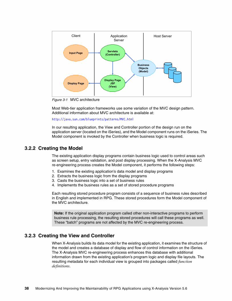
Figure 3-1 MVC architecture
Most Web-tier application frameworks use some variation of the MVC design pattern. Additional information about MVC architecture is available at:
http://java.sun.com/blueprints/patterns/MVC.html
In our resulting application, the View and Controller portion of the design run on the application server (located on the iSeries), and the Model component runs on the iSeries. The Model component is invoked by the Controller when business logic is required.
3.2.2 Creating the ModelThe existing application display programs contain business logic used to control areas such as screen setup, entry validation, and post display processing. When the X-Analysis MVC re-engineering process creates the Model component, it performs the following steps:
1. Examines the existing application’s data model and display programs2. Extracts the business logic from the display programs3. Casts the business logic into a set of business rules4. Implements the business rules as a set of stored procedure programs
Each resulting stored procedure program consists of a sequence of business rules described in English and implemented in RPG. These stored procedures form the Model component of the MVC architecture.
3.2.3 Creating the View and ControllerWhen X-Analysis builds its data model for the existing application, it examines the structure of the model and creates a database of display and flow of control information on the iSeries. The X-Analysis MVC re-engineering process enhances this database with additional information drawn from the existing application’s program logic and display file layouts. The resulting metadata for each individual view is grouped into packages called function definitions.
Display Page
Servlets(Controller)
Display PageJSF
(View)
Input Page
BusinessObjects(Model)
Client Host ServerApplicationServer
Note: If the original application program called other non-interactive programs to perform business rule processing, the resulting stored procedures will call these programs as well. These “batch” programs are not affected by the MVC re-engineering process.
38 Modernizing And Improving the Maintainability of RPG Applications using X-Analysis Version 5.6
A function definition contains data regarding:
� Presentation of the user interface (the window layout)� Necessary data access methods for the View� Database driven validations and selections� When the business rule code from the Model program is invoked� Navigation from its view to other views
These function definitions are used by either a Web browser user interface or rich client user interface to implement the View-Controller components of the re-engineered application.
Web browser user interfaceThere are two separate methods we can use to implement a Web browser user interface using the function definitions:
� The application can be run under the X-Web framework on the application server. The X-Web framework implements the Controller, and accesses the function definition layout information at run time to dynamically build the Views as needed. The Views are accessed by a Web browser on the client PC.
� The X-Analysis JSF Generator can use the function definitions to generate a Web project consisting of Java class files, JavaServer Faces (JSF), and JavaBeans. The Java components can then be run either with or without the X-Web framework. The application server uses the generated JavaServer Faces to implement the Views. The Views are accessed by a Web browser on the client PC.
Rich client user interfaceUnder the rich client implementation, the X-Browse extension acts as a rich client running on the PC. X-Browse implements the Controller function and uses the function definitions to dynamically build the resulting View.
The X-Analysis client uses the rich client interface to implement its function definition editor. When we use the function definition editor in 3.6.1, “Viewing the standard function definitions” on page 47, you see an example of the rich client implementation. However, since the focus of this chapter is on developing the Web browser user interface, we do not further discuss the rich client user interface.
Model accessRegardless of how the View-Controller is implemented, the execution of the Model is the same. All three Controller implementations call the same stored procedures that were built on the iSeries. Only the call methodology varies.
3.2.4 Working with function definitionsFunction definitions are generated automatically by X-Analysis. However, some design work tuning the automatically generated function definitions is usually required to achieve the desired application. This design work can include:
� Modifying or enhancing the window layouts� Modifying or enhancing the links to other windows� Modifying or enhancing the stored procedure calls� Modifying or enhancing the window functionality (add, display, change, delete)
Note: View, Model, and Controller, when capitalized, refer to View, Model, and Controller from MVC architecture.
Chapter 3. Re-engineering an existing application to the MVC architecture 39
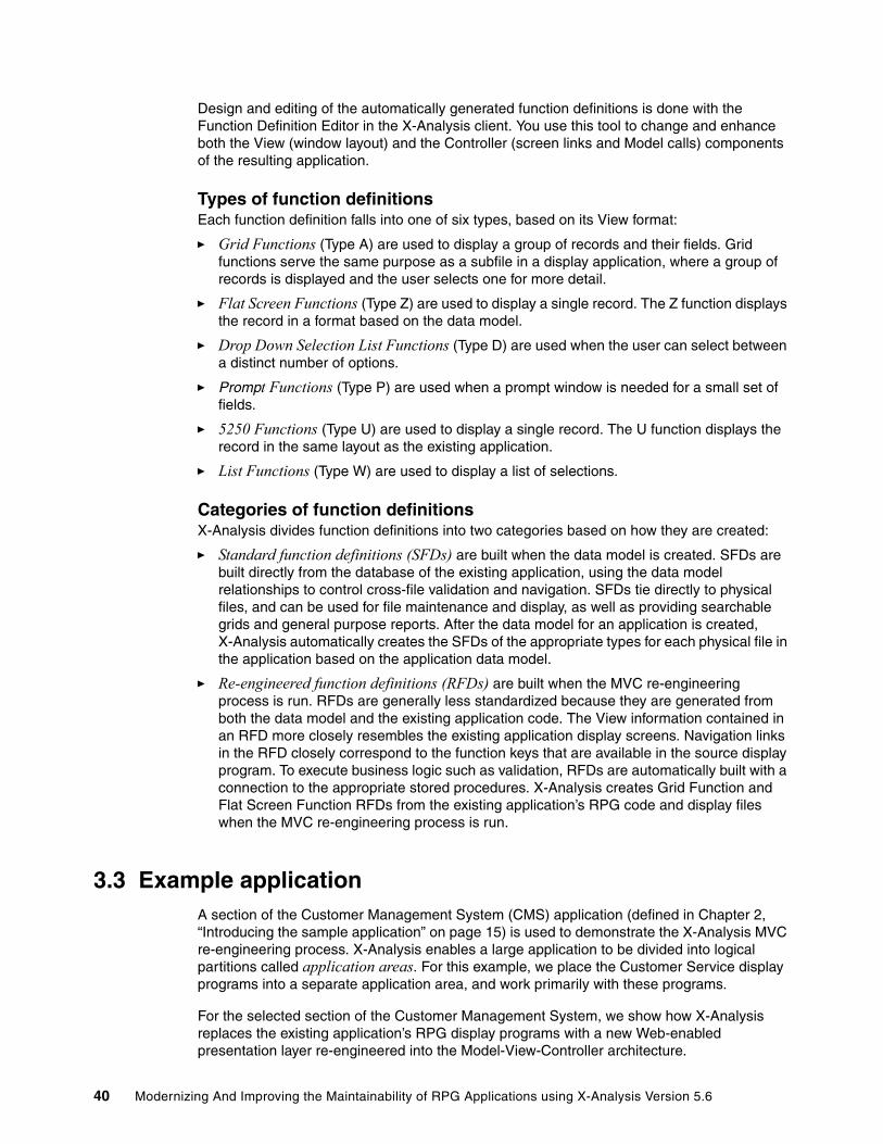
Design and editing of the automatically generated function definitions is done with the Function Definition Editor in the X-Analysis client. You use this tool to change and enhance both the View (window layout) and the Controller (screen links and Model calls) components of the resulting application.
Types of function definitionsEach function definition falls into one of six types, based on its View format:
� Grid Functions (Type A) are used to display a group of records and their fields. Grid functions serve the same purpose as a subfile in a display application, where a group of records is displayed and the user selects one for more detail.
� Flat Screen Functions (Type Z) are used to display a single record. The Z function displays the record in a format based on the data model.
� Drop Down Selection List Functions (Type D) are used when the user can select between a distinct number of options.
� Prompt Functions (Type P) are used when a prompt window is needed for a small set of fields.
� 5250 Functions (Type U) are used to display a single record. The U function displays the record in the same layout as the existing application.
� List Functions (Type W) are used to display a list of selections.
Categories of function definitionsX-Analysis divides function definitions into two categories based on how they are created:
� Standard function definitions (SFDs) are built when the data model is created. SFDs are built directly from the database of the existing application, using the data model relationships to control cross-file validation and navigation. SFDs tie directly to physical files, and can be used for file maintenance and display, as well as providing searchable grids and general purpose reports. After the data model for an application is created, X-Analysis automatically creates the SFDs of the appropriate types for each physical file in the application based on the application data model.
� Re-engineered function definitions (RFDs) are built when the MVC re-engineering process is run. RFDs are generally less standardized because they are generated from both the data model and the existing application code. The View information contained in an RFD more closely resembles the existing application display screens. Navigation links in the RFD closely correspond to the function keys that are available in the source display program. To execute business logic such as validation, RFDs are automatically built with a connection to the appropriate stored procedures. X-Analysis creates Grid Function and Flat Screen Function RFDs from the existing application’s RPG code and display files when the MVC re-engineering process is run.
3.3 Example applicationA section of the Customer Management System (CMS) application (defined in Chapter 2, “Introducing the sample application” on page 15) is used to demonstrate the X-Analysis MVC re-engineering process. X-Analysis enables a large application to be divided into logical partitions called application areas. For this example, we place the Customer Service display programs into a separate application area, and work primarily with these programs.
For the selected section of the Customer Management System, we show how X-Analysis replaces the existing application’s RPG display programs with a new Web-enabled presentation layer re-engineered into the Model-View-Controller architecture.
40 Modernizing And Improving the Maintainability of RPG Applications using X-Analysis Version 5.6

3.4 X-Analysis MVC re-engineering summaryLike most large tasks, the MVC re-engineering process is broken down into a number of discrete steps, which consist of:
1. Partitioning the application. You identify the section of the application you are re-engineering, create an application area, and assign the application section to the application area.
2. Review the standard function definitions. You identify the SFDs in the application area and review their format layouts using the function definition editor.
3. Customize the standard function definitions. You identify the changes needed to fit the application requirements and update the SFDs using the function definition editor.
4. Run the X-Analysis MVC re-engineering process. This generates the business rules from the application code, then generates the stored procedures from the business rules, and finally generates RFDs from the application code, display files, and database.
5. Review the re-engineered function definitions. You identify the RFDs in the application area, and review their format layouts using the function definition editor.
6. Review the re-engineered stored procedures. You identify the stored procedures in the application area, view the business rules contained in the stored procedures, and review the links between the function definitions and the stored procedures.
7. Customize the re-engineered function definitions. You identify the changes needed to fit the application requirements and update the RFDs using the function definition editor.
8. Implement the Web-enabled application using the X-Web framework. You start and configure the X-Web server, and use the X-Web server to run the Web-enabled application.
9. Implement the Web-enabled application in Java. You create Java components with the X-Analysis client, and then modify them using WDSc. You run the resulting Java application using the X-Web framework on the X-Web server.
10.Review the JSF, JavaBean, and stored procedure code. You review the call path between the JSF displayed in the Web browser, and the stored procedures on the iSeries.
3.5 Partitioning the applicationThe partition of the CMS system we work with is the display programs most used by the Customer Service area. These display programs are all accessed from the Customers Main Menu (Figure 3-2 on page 42). Our partition includes the menu and all of the screen display programs directly or indirectly available from that menu.
The RPG program XCMMENU implements the Customers Main Menu.
Note: In actual practice, there is some flexibility to the order in which these steps are executed. For example, the MVC re-engineering process can be run immediately after logically separating the application. The SFDs and RFDs would then be reviewed and customized together. Also, if the desired end result is running the Web-enabled application using JSF, the step of running the Web-enabled application in the X-Web framework could be bypassed.
Chapter 3. Re-engineering an existing application to the MVC architecture 41
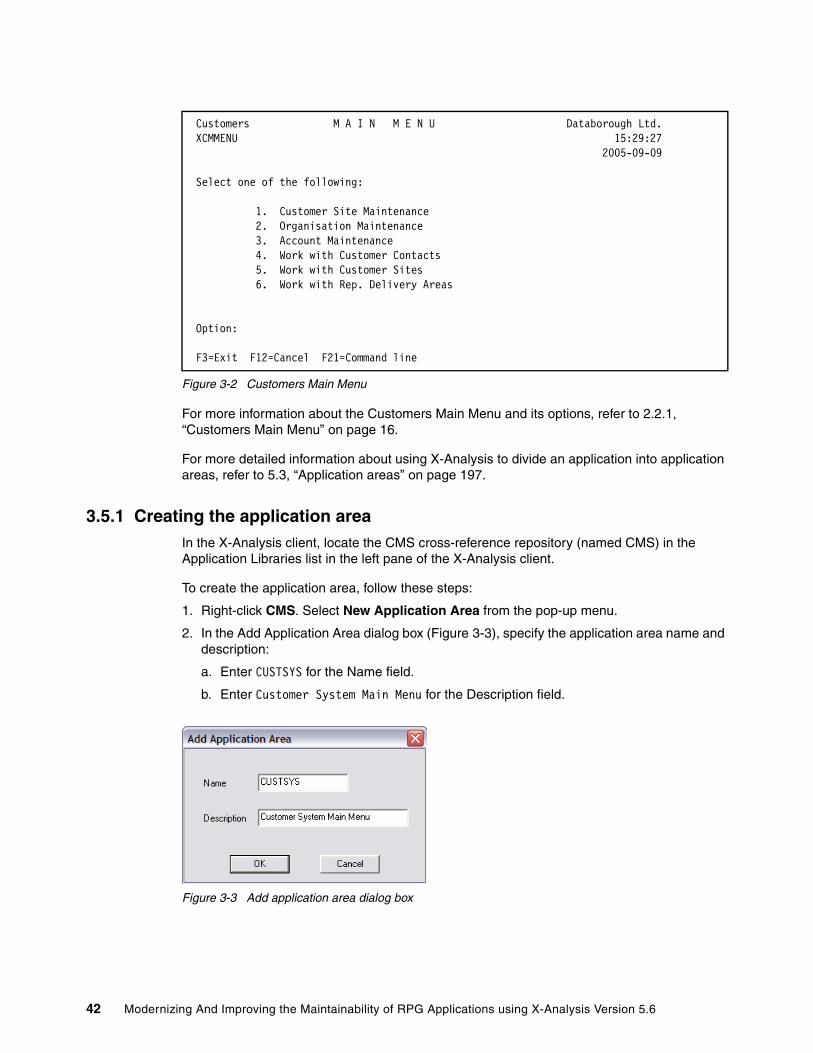
Figure 3-2 Customers Main Menu
For more information about the Customers Main Menu and its options, refer to 2.2.1, “Customers Main Menu” on page 16.
For more detailed information about using X-Analysis to divide an application into application areas, refer to 5.3, “Application areas” on page 197.
3.5.1 Creating the application areaIn the X-Analysis client, locate the CMS cross-reference repository (named CMS) in the Application Libraries list in the left pane of the X-Analysis client.
To create the application area, follow these steps:
1. Right-click CMS. Select New Application Area from the pop-up menu.
2. In the Add Application Area dialog box (Figure 3-3), specify the application area name and description:
a. Enter CUSTSYS for the Name field.
b. Enter Customer System Main Menu for the Description field.
Figure 3-3 Add application area dialog box
Customers M A I N M E N U Databorough Ltd. XCMMENU 15:29:27 2005-09-09 Select one of the following: 1. Customer Site Maintenance 2. Organisation Maintenance 3. Account Maintenance 4. Work with Customer Contacts 5. Work with Customer Sites 6. Work with Rep. Delivery Areas
Option: F3=Exit F12=Cancel F21=Command line
42 Modernizing And Improving the Maintainability of RPG Applications using X-Analysis Version 5.6

3.5.2 Adding the Customers Main Menu to the application areaIn the X-Analysis client, perform the following steps to assign the Customer Service menu and the programs it calls to the new CUSTSYS application area:
1. Locate and expand the CMS cross-reference repository (named CMS) in the Application Libraries list in the left pane of the X-Analysis client.
2. In the expanded CMS cross-reference repository, double-click Programs.
3. In the Work with Objects dialog box, click OK.
4. From the resulting list, right-click XCMMENU and select Add to Application Area with Related Objects (Figure 3-4).
Figure 3-4 XCMMENU selection
Chapter 3. Re-engineering an existing application to the MVC architecture 43

5. In the Add XCMMENU to Application Area with Related Objects dialog box (Figure 3-5), perform the following steps:
a. Select the CUSTSYS application area.
b. Select Include the files referenced by program from the first pull-down list.
c. Select Include complete stack of programs called from the second pull-down list.
d. Select Include files referenced by any included program from the third pull-down list.
Figure 3-5 Add XCMMENU to Application Area with Related Objects
e. Click OK.
f. The completion message Object and its related objects added to Application area appears in the X-Analysis client status bar located at the bottom of window.
44 Modernizing And Improving the Maintainability of RPG Applications using X-Analysis Version 5.6

3.6 Reviewing the application’s standard function definitionsFigure 3-6 shows how X-Analysis creates the data model and standard function definitions. The X-Analysis data modeling program extracts the data model from the existing application’s program code and database. Then the X-Analysis Function Builder uses this data model to build a set of SFDs for each of the physical files in the application.
Figure 3-6 X-Analysis standard function definition generation
These SFDs focus on providing view and controller information related to the display and maintenance of the application’s physical files. In some cases, these SFDs contain all View and Controller functionality needed for that file in the final re-engineered application.
3.6.1 Viewing the standard function definitionsTo view the function definitions in the X-Analysis client, perform the following steps:
1. In the left pane of the X-Analysis client window, locate and expand the CUSTSYS application area under the CMS cross-reference repository.
2. In the expanded CUSTSYS application area, double-click Functions.
3. In the Work with Objects dialog box, click OK.
4. The function list for the CUSTSYST application area appears in the right pane of the X-Analysis client.
RPG Code
Data Modeling Program
Analyzes legacy applicationand builds the Data Model
Database
Existing Application
Function Builder Program
Compacts the Data Model
Data Model
Standard FunctionDefinitions
Chapter 3. Re-engineering an existing application to the MVC architecture 45
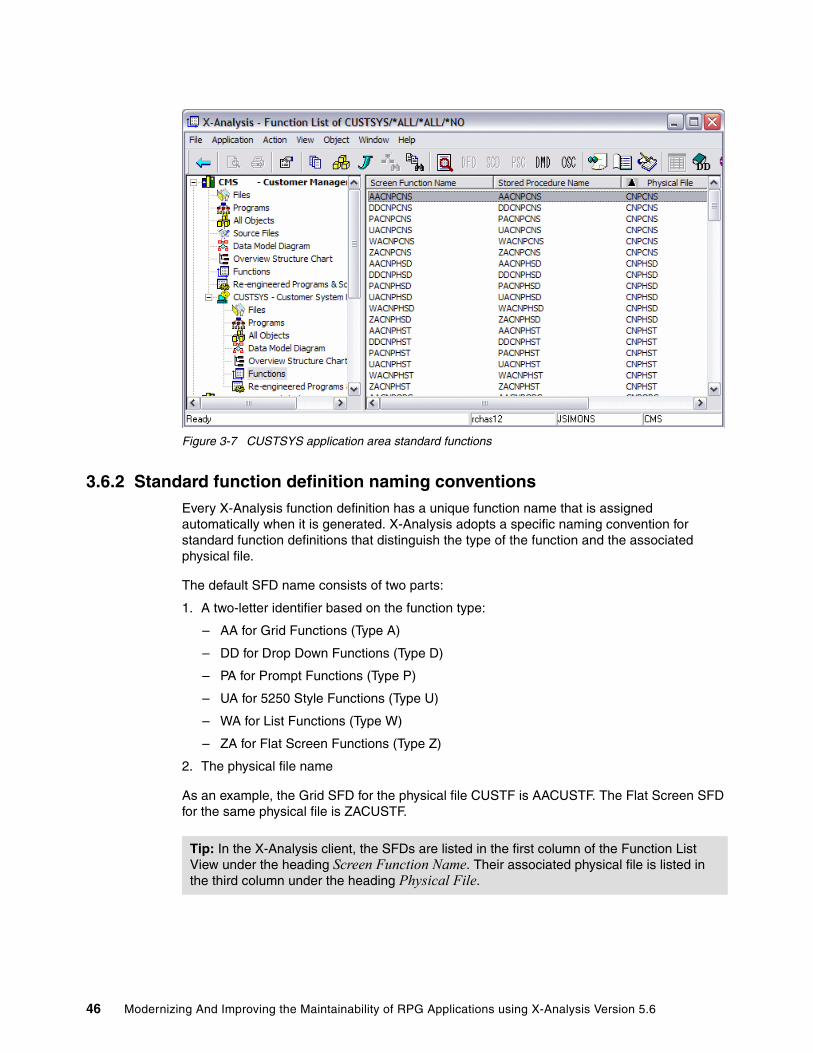
Figure 3-7 CUSTSYS application area standard functions
3.6.2 Standard function definition naming conventionsEvery X-Analysis function definition has a unique function name that is assigned automatically when it is generated. X-Analysis adopts a specific naming convention for standard function definitions that distinguish the type of the function and the associated physical file.
The default SFD name consists of two parts:
1. A two-letter identifier based on the function type:
– AA for Grid Functions (Type A)
– DD for Drop Down Functions (Type D)
– PA for Prompt Functions (Type P)
– UA for 5250 Style Functions (Type U)
– WA for List Functions (Type W)
– ZA for Flat Screen Functions (Type Z)
2. The physical file name
As an example, the Grid SFD for the physical file CUSTF is AACUSTF. The Flat Screen SFD for the same physical file is ZACUSTF.
Tip: In the X-Analysis client, the SFDs are listed in the first column of the Function List View under the heading Screen Function Name. Their associated physical file is listed in the third column under the heading Physical File.
46 Modernizing And Improving the Maintainability of RPG Applications using X-Analysis Version 5.6
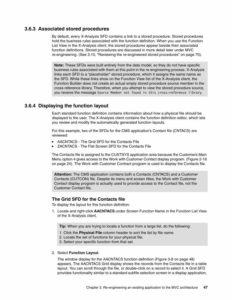
3.6.3 Associated stored proceduresBy default, every X-Analysis SFD contains a link to a stored procedure. Stored procedures hold the business rules associated with the function definition. When you use the Function List View in the X-Analysis client, the stored procedures appear beside their associated function definitions. Stored procedures are discussed in more detail later under MVC re-engineering. (See 3.10, “Reviewing the re-engineered stored procedures” on page 70).
3.6.4 Displaying the function layoutEach standard function definition contains information about how a physical file should be displayed to the user. The X-Analysis client contains the function definition editor, which lets you review and modify the automatically generated function layouts.
For this example, two of the SFDs for the CMS application’s Contact file (CNTACS) are reviewed:
� AACNTACS - The Grid SFD for the Contacts File� ZACNTACS - The Flat Screen SFD for the Contacts File
The Contacts file is assigned to the CUSTSYS application area because the Customers Main Menu option 4 gives access to the Work with Customer Contact display program. (Figure 2-16 on page 24). The Work with Customer Contract program is used to display the Contacts file.
The Grid SFD for the Contacts fileTo display the layout for this function definition:
1. Locate and right-click AACNTACS under Screen Function Name in the Function List View of the X-Analysis client.
2. Select Function Layout.
The window display for the AACNTACS function definition (Figure 3-8 on page 48) appears. The AACNTACS Grid display shows the records from the Contacts file in a table layout. You can scroll through the file, or double-click on a record to select it. A Grid SFD provides functionality similar to a standard subfile selection screen in a display application,
Note: These SFDs were built entirely from the data model, so they do not have specific business rules associated with them at this point in the re-engineering process. X-Analysis links each SFD to a “placeholder” stored procedure, which it assigns the same name as the SFD. While these links show on the Function View list of the X-Analysis client, the Function Builder does not create an actual empty stored procedure source member in the cross-reference library. Therefore, when you attempt to view the stored procedure source, you receive the message Source Member not found in this cross-reference library.
Attention: The CMS application contains both a Contacts (CNTACS) and a Customer Contacts (CUTCON) file. Despite its menu and screen titles, the Work with Customer Contact display program is actually used to provide access to the Contact file, not the Customer Contact file.
Tip: When you are trying to locate a function from a large list, do the following:
1. Click the Physical File column header to sort the list by file name. 2. Locate the set of functions for your physical file. 3. Select your specific function from that set.
Chapter 3. Re-engineering an existing application to the MVC architecture 47

but it removes many of the subfile limitations while adding additional features and functionality.
Figure 3-8 AACNTACS function layout
The Flat Screen SFD for the Contacts fileTo display the layout for ZACNTACS Flat Screen SFD display, double-click any of the table entries in the AACNTACS Grid SFD display. Alternately, you can close the Grid SFD display and take the following steps:
1. Locate and right-click ZACNTACS under Screen Function Name in the Function List View of the X-Analysis client.
2. Select Function Layout.
The window display for the ZACNTACS function definition (Figure 3-9) appears. The ZACNTACS Flat Screen SDF shows the individual record from the Contacts file.
Figure 3-9 ZACNTACS function layout
48 Modernizing And Improving the Maintainability of RPG Applications using X-Analysis Version 5.6
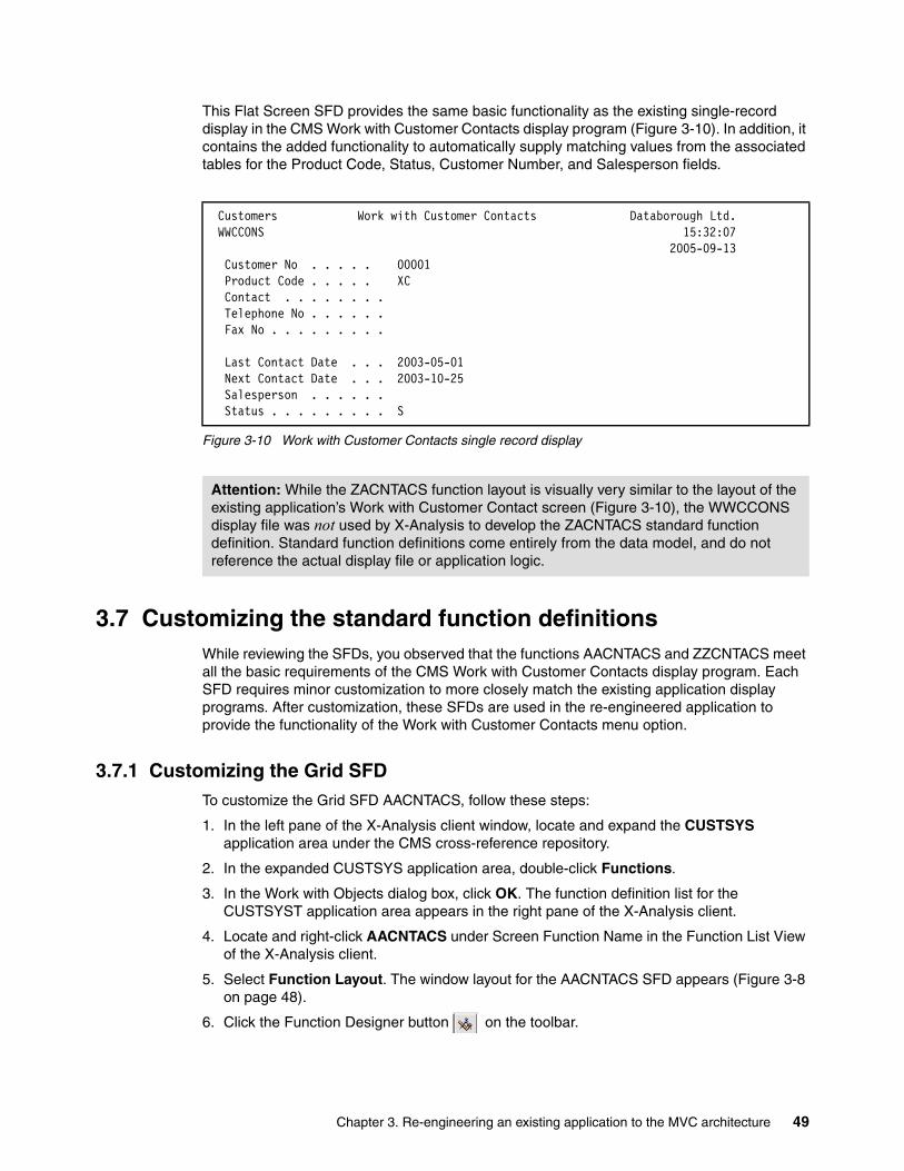
This Flat Screen SFD provides the same basic functionality as the existing single-record display in the CMS Work with Customer Contacts display program (Figure 3-10). In addition, it contains the added functionality to automatically supply matching values from the associated tables for the Product Code, Status, Customer Number, and Salesperson fields.
Figure 3-10 Work with Customer Contacts single record display
3.7 Customizing the standard function definitionsWhile reviewing the SFDs, you observed that the functions AACNTACS and ZZCNTACS meet all the basic requirements of the CMS Work with Customer Contacts display program. Each SFD requires minor customization to more closely match the existing application display programs. After customization, these SFDs are used in the re-engineered application to provide the functionality of the Work with Customer Contacts menu option.
3.7.1 Customizing the Grid SFDTo customize the Grid SFD AACNTACS, follow these steps:
1. In the left pane of the X-Analysis client window, locate and expand the CUSTSYS application area under the CMS cross-reference repository.
2. In the expanded CUSTSYS application area, double-click Functions.
3. In the Work with Objects dialog box, click OK. The function definition list for the CUSTSYST application area appears in the right pane of the X-Analysis client.
4. Locate and right-click AACNTACS under Screen Function Name in the Function List View of the X-Analysis client.
5. Select Function Layout. The window layout for the AACNTACS SFD appears (Figure 3-8 on page 48).
6. Click the Function Designer button on the toolbar.
Customers Work with Customer Contacts Databorough Ltd. WWCCONS 15:32:07 2005-09-13 Customer No . . . . . 00001 Product Code . . . . . XC Contact . . . . . . . . Telephone No . . . . . . Fax No . . . . . . . . . Last Contact Date . . . 2003-05-01 Next Contact Date . . . 2003-10-25 Salesperson . . . . . . Status . . . . . . . . . S
Attention: While the ZACNTACS function layout is visually very similar to the layout of the existing application’s Work with Customer Contact screen (Figure 3-10), the WWCCONS display file was not used by X-Analysis to develop the ZACNTACS standard function definition. Standard function definitions come entirely from the data model, and do not reference the actual display file or application logic.
Chapter 3. Re-engineering an existing application to the MVC architecture 49
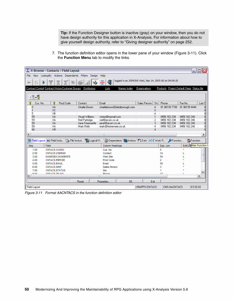
7. The function definition editor opens in the lower pane of your window (Figure 3-11). Click the Function Menu tab to modify the links.
Figure 3-11 Format AACNTACS in the function definition editor
Tip: If the Function Designer button is inactive (gray) on your window, then you do not have design authority for this application in X-Analysis. For information about how to give yourself design authority, refer to “Giving designer authority” on page 252.
50 Modernizing And Improving the Maintainability of RPG Applications using X-Analysis Version 5.6

8. Remove the undesired links:
a. Locate the Caption column in the Function Menu tab.
b. Select the check box in the Delete column (Figure 3-12) beside each of these items:
• Contract Control
• Contract History
• Customer Group
• Distributors
• List
• Name Index
• Organizations
• Project Default Steps
c. Click OK.
Figure 3-12 Deleting links in format AACNTACS
Chapter 3. Re-engineering an existing application to the MVC architecture 51
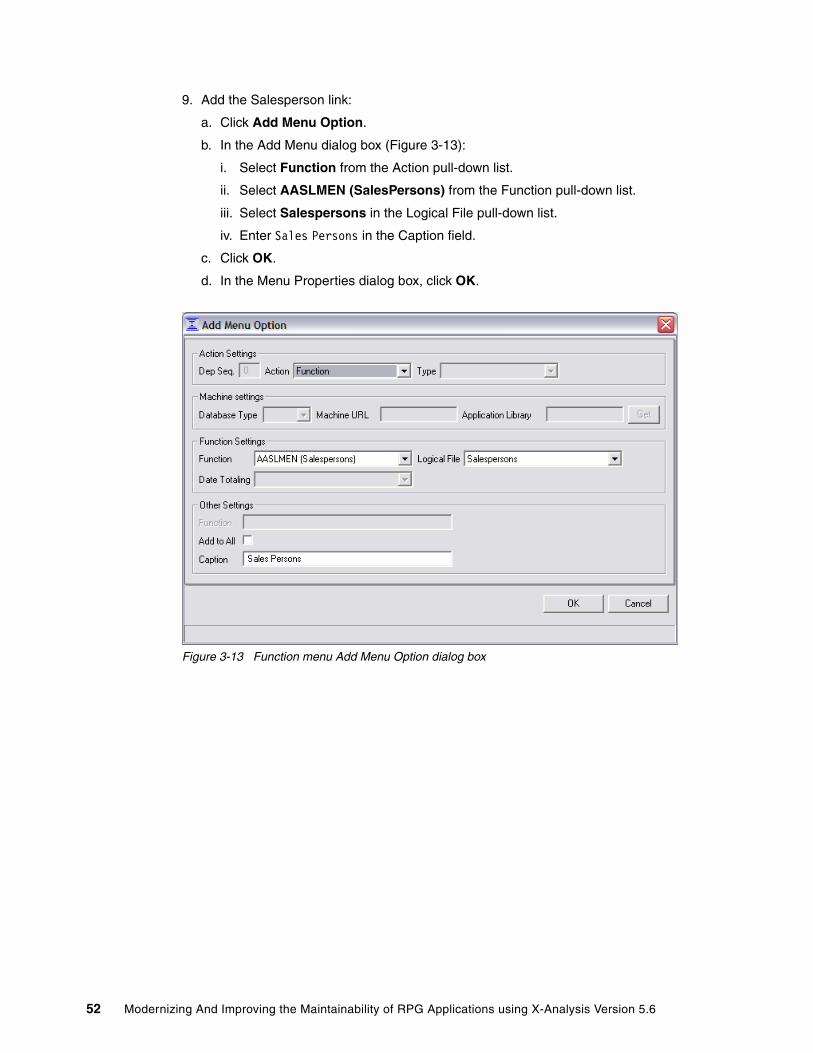
9. Add the Salesperson link:
a. Click Add Menu Option.
b. In the Add Menu dialog box (Figure 3-13):
i. Select Function from the Action pull-down list.
ii. Select AASLMEN (SalesPersons) from the Function pull-down list.
iii. Select Salespersons in the Logical File pull-down list.
iv. Enter Sales Persons in the Caption field.
c. Click OK.
d. In the Menu Properties dialog box, click OK.
Figure 3-13 Function menu Add Menu Option dialog box
52 Modernizing And Improving the Maintainability of RPG Applications using X-Analysis Version 5.6

10.Add the Site link. Perform the following steps:
a. Click Add Menu Option.
b. In the Add Menu dialog box:
i. Select Function from the Action pull-down list.
ii. Select AACUSTF (Sites) from the Function pull-down list.
iii. Select Sites by Number in the Logical File pull-down list.
iv. Enter Customer Sites in the Caption Field.
c. Click OK.
d. In the Menu Properties dialog box, click OK.
11.Change the column headings to spell out Customer Number, Product Code, Status, Last Contact Date, and Next Contact Date:
a. Click the Field Layout tab of the function definition editor.
b. Locate the Column Heading column in the Field Layout tab and perform these steps:
i. Click Cus. No (Figure 3-14) and enter Customer Number.
ii. Click Prod Code and enter Product Code.
iii. Click Sts and enter Status.
iv. Click Last Cnt Date and enter Last Contact Date.
v. Click Next Cnt Date and enter Next Contact Date.
vi. Click OK.
Figure 3-14 Changing column heading in format AACNTACS
Chapter 3. Re-engineering an existing application to the MVC architecture 53

12.Change the order of the fields displayed in the grid to put Last Contact Date immediately after Contact, by doing these steps:
a. Click the Field Layout tab of the function definition editor.
b. Locate the Seq. column in the Field Layout tab. Click Last Contact Date and enter 2.5 into the Seq. field.
c. Click OK.
Figure 3-15 Changing field order in format AACNTACS
13.Click Exit to close the function definition editor, and review the final function definition (Figure 3-16).
Figure 3-16 Final layout for format AACNTACS
54 Modernizing And Improving the Maintainability of RPG Applications using X-Analysis Version 5.6

You can click the various links to demonstrate how control flows between layouts. Click the Back button on the toolbar to return to the previous window. When you are done reviewing the layout, close the X-Browse - Contracts window to return to the X-Analysis client.
3.7.2 Customizing the Flat Screen SDFTo customize the Flat Screen SDF ZACNTACS, follow these steps:
1. Locate and right-click ZACNTACS under Screen Function Name in the Function List View of the X-Analysis client.
2. Select Function Layout. The window display for the ZACNTACS SDF appears (Figure 3-9 on page 48).
3. Click the Function Designer button on the toolbar.
4. The function definition editor opens in the lower pane of your window (Figure 3-17). Click the Function Menu tab to modify the links.
Figure 3-17 Format ZACNTACS in the function definition editor
Chapter 3. Re-engineering an existing application to the MVC architecture 55

5. Remove the undesired links as follows:
a. Locate the Caption column in the Function Menu tab.
b. Select the check box in the Delete column (Figure 3-18) beside each of the following items:
• Contract Control
• Contract History
• Customer Group
• Distributors
• List
• Name Index
• Organizations
• Project Default Steps
c. Click OK.
Figure 3-18 Deleting links in format ZACNTACS
56 Modernizing And Improving the Maintainability of RPG Applications using X-Analysis Version 5.6

6. Add the Salesperson link by performing the following steps:
a. Click Add Menu Option.
b. In the Add Menu Option dialog box (Figure 3-19):
i. Select Function from the Action pull-down list.
ii. Select AASLMEN (SalesPersons) from the Function pull-down list.
iii. Select Salespersons in the Logical File pull-down list.
iv. Enter Sales Persons in the Caption field.
c. Click OK.
d. In the Menu Properties dialog box, click OK.
Figure 3-19 Function menu Add Menu Option dialog box
7. Add the Site link:
a. Click Add Menu Option.
b. In the Add Menu Option dialog box:
i. Select Function from the Action pull-down list.
ii. Select AACUSTF (Sites) from the Function pull-down list.
iii. Select Sites by Number in the Logical File pull-down list.
iv. Enter Customer Sites in the Caption Field.
c. Click OK.
d. In the Menu Properties dialog box, click OK.
8. Change the field text to spell out Customer Number, Product Code, Status, Last Contact Date, and Next Contact Date:
a. Click the Field Layout tab of the function definition editor.
Chapter 3. Re-engineering an existing application to the MVC architecture 57

b. Locate the Constant/Field Name column in the Field Layout tab.
i. Click Prod Code (Figure 3-20) and enter Product Code.
ii. Click Sts and enter Status.
iii. Click Cus. No and enter Customer Number.
iv. Click Last Cnt Date and enter Last Contact Date.
v. Click Next Cnt Date and enter Next Contact Date.
vi. Click OK.
Figure 3-20 Changing field text in format ZACNTACS
9. Change the order in which the fields are displayed to more closely match the existing display layout (Figure 3-10 on page 49):
a. Click the Field Layout tab of the function definition editor.
b. Locate the Row column in the Field Layout tab.
i. Click Product Code and enter 2 in the row field.
ii. Click PRPCD and enter 2 in the Row field.
iii. Click PDESF and enter 2 in the Row field.
iv. Click Status and enter 11 in the Row field.
v. Click STATUS and enter 11 in the Row field.
vi. Click STSTXT and enter 11 in the Row field.
vii. Click Customer Number and enter 1 in the Row field.
58 Modernizing And Improving the Maintainability of RPG Applications using X-Analysis Version 5.6
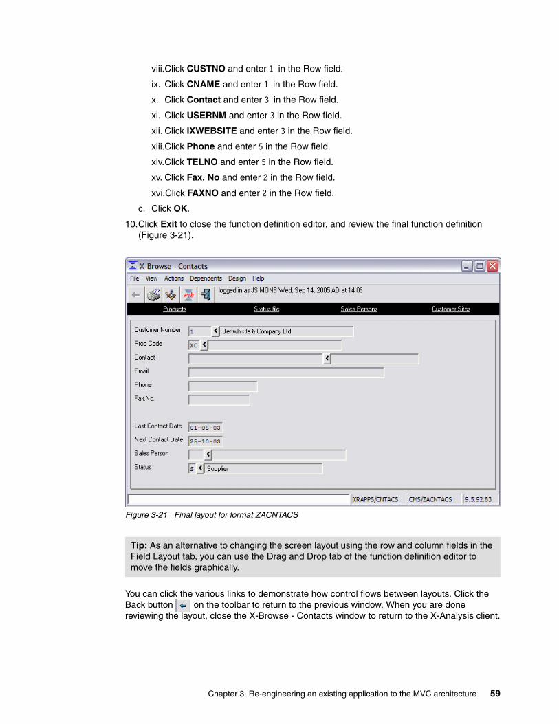
viii.Click CUSTNO and enter 1 in the Row field.
ix. Click CNAME and enter 1 in the Row field.
x. Click Contact and enter 3 in the Row field.
xi. Click USERNM and enter 3 in the Row field.
xii. Click IXWEBSITE and enter 3 in the Row field.
xiii.Click Phone and enter 5 in the Row field.
xiv.Click TELNO and enter 5 in the Row field.
xv. Click Fax. No and enter 2 in the Row field.
xvi.Click FAXNO and enter 2 in the Row field.
c. Click OK.
10.Click Exit to close the function definition editor, and review the final function definition (Figure 3-21).
Figure 3-21 Final layout for format ZACNTACS
You can click the various links to demonstrate how control flows between layouts. Click the Back button on the toolbar to return to the previous window. When you are done reviewing the layout, close the X-Browse - Contacts window to return to the X-Analysis client.
Tip: As an alternative to changing the screen layout using the row and column fields in the Field Layout tab, you can use the Drag and Drop tab of the function definition editor to move the fields graphically.
Chapter 3. Re-engineering an existing application to the MVC architecture 59

3.8 Running the X-Analysis MVC re-engineering processThe X-Analysis MVC re-engineering process consists of three logical components (Figure 3-22).
Figure 3-22 X-Analysis re-engineering components
� The Business Rule Extractor reviews the existing application RPG code for the display programs and separates the business logic code from the screen control and presentation code. It then parses the business logic code into a set of business rules that are stored in the business rules database.
� The Stored Procedure Generator uses the business rules database to generate the RPG stored procedure programs. The generated stored procedure programs form the Model component of the MVC architecture.
� The Function Builder uses the RPG code and display files from the existing application’s display programs to build the re-engineered function definitions (RFDs). The RFDs are used for the View-Controller components of the MVC architecture.
These three logical components are tightly coupled and cannot be run separately. When the X-Analysis MVC re-engineering process is run, all three components are executed automatically.
3.8.1 Running the MVC re-engineering process over an application areaFor the CMS system, the re-engineered function definitions for the CUSTSYS application area are generated as a group:
1. In the left pane of the X-Analysis client window, locate the CUSTSYS application area under the CMS cross-reference repository.
Stored ProcedureGenerator
Existing Application
RPG Code DatabaseDisplay Files
Re-engineeredFunction Definitions(View – Controller)
Business RuleExtractor
Business RulesDatabase
Stored ProcedurePrograms
(Model)
FunctionBuilder
60 Modernizing And Improving the Maintainability of RPG Applications using X-Analysis Version 5.6
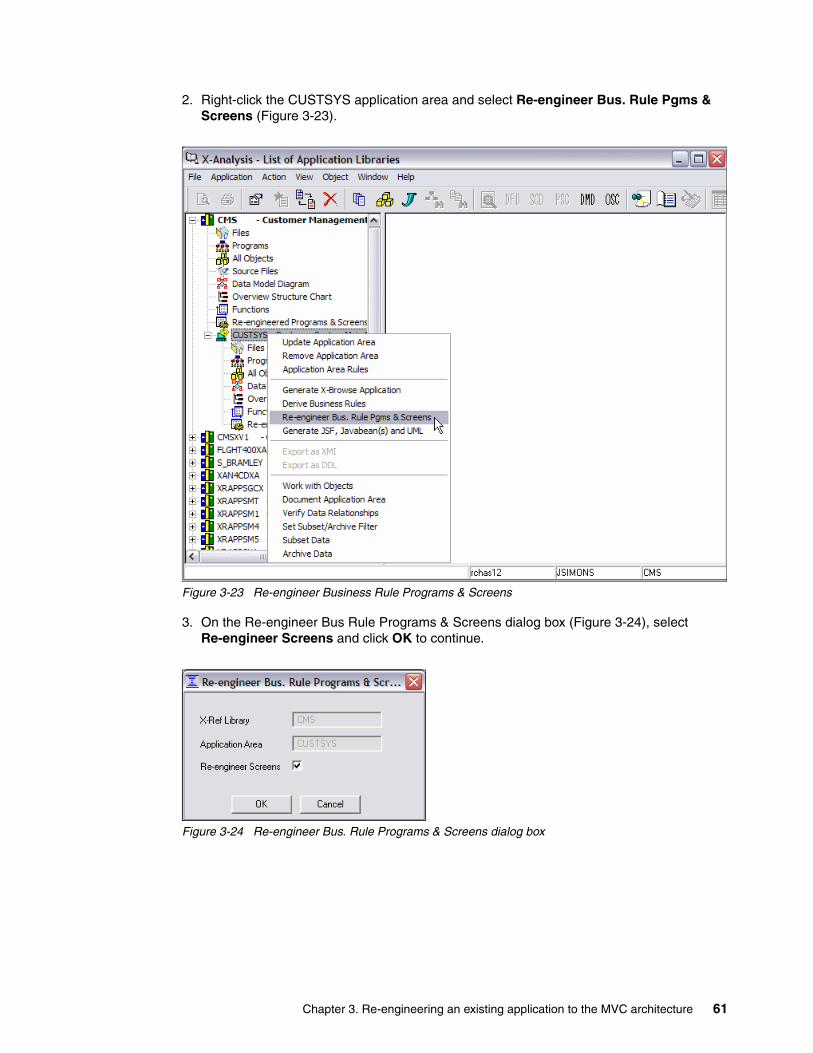
2. Right-click the CUSTSYS application area and select Re-engineer Bus. Rule Pgms & Screens (Figure 3-23).
Figure 3-23 Re-engineer Business Rule Programs & Screens
3. On the Re-engineer Bus Rule Programs & Screens dialog box (Figure 3-24), select Re-engineer Screens and click OK to continue.
Figure 3-24 Re-engineer Bus. Rule Programs & Screens dialog box
Chapter 3. Re-engineering an existing application to the MVC architecture 61

4. The Re-engineer Bus Rule Programs & Screens Status Box (Figure 3-25) appears as the business rules, stored procedures, and RFD are generated interactively from the existing application programs. When the Job Completed message appears, click Close.
Figure 3-25 Re-engineer Bus. Rule Programs & Screens status box
5. Immediately repeat steps 2 on page 61, 3 on page 61, and 4. When running the MVC re-engineering process in a group, there are some situations where a processing order issue can cause errors in the generated RFDs. For this reason it is important to run the process at least twice, which will ensure that the correct RFDs are built.
3.8.2 Running the MVC re-engineering process over an individual programThe MVC re-engineering process may also be run over an individual existing application display program:
1. In the left pane of the X-Analysis client window, locate and expand the CUSTSYS application area under the CMS cross-reference repository.
2. In the expanded CUSTSYS application area, double-click Programs.
3. In the Work with Objects dialog box, click OK.
Notes:
� The X-Analysis Function Builder reviews the existing display application in a group build in serial order. It checks each existing program to determine what other display programs are accessed, and then checks those programs to see whether they have RFDs. If an RFD for a called program is not available, the Function Builder will not correctly build the links between the descriptions. For example, if Program A calls Program B, and both will have RFDs, when Program A’s RFDs are generated, the Function Builder will not find Program B’s RFDs, as it has not processed Program B yet. This will result in the RFDs for Program A not linking correctly to the RFDs for program B. Performing a second run corrects this problem, because when Program A’s RFDs are rebuilt, the RFDs for Program B will exist.
� The Re-engineer Bus. Rule Pgms & Screens function in X-Analysis may be run repeatedly. When an RFD is regenerated, it simply replaces the prior version.
62 Modernizing And Improving the Maintainability of RPG Applications using X-Analysis Version 5.6

4. The object list for the CUSTSYST application area appears in the right column of the X-Analysis client.
a. Locate the interactive program CUSFMAINT.
b. Right-click CUSFMAINT and select Re-engineer Bus. Rule Pgms & Screens (Figure 3-26).
Figure 3-26 Individual Re-engineer Bus. Rule Pgms & Screens
c. On the Re-engineer Bus Rule Programs & Screens dialog box (Figure 3-27), select Update Screens and click OK to continue.
Figure 3-27 Individual Re-engineer Bus Rule Pgms & Screens dialog box
Chapter 3. Re-engineering an existing application to the MVC architecture 63

d. The Re-engineer Bus Rule Pgms & Screens status box (Figure 3-25 on page 62) appears as the re-engineered functions are generated from the existing application program interactively. When the Job Completed message appears, click Close.
3.9 Reviewing the re-engineered function definitionsWhen we run the MVC re-engineering process, it invokes the Function Builder to create a set of re-engineered function definitions based on the application business and display logic.
To view the RFDs in the X-Analysis client, perform the following steps:
1. In the left pane of the X-Analysis client window, locate and expand the CUSTSYS application area under the CMS cross-reference repository.
2. In the expanded CUSTSYS application area, double-click Re-engineered Program & Screens.
3. The Re-engineered Programs View for the CUSTSYS application area appears in the right pane of the X-Analysis client window (Figure 3-28). The RFDs appear in the Screen Function Name column.
Figure 3-28 CUSTSYS Re-engineered Programs & Screens
Tip: Be careful not to confuse the Re-engineer Bus. Rule Pgms & Screens option, which generates the RFDs and stored procedures, with the Re-engineered Programs & Screens option that immediately follows it, which enables you to view the RFDs and stored procedures that you have already generated.
Important: In some cases, the Function Builder recognizes that building an RFD would be redundant, because a SFD already exists that provides the required functionality. In these cases, an RFD is not built, and instead X-Analysis assigns the re-engineered stored procedure to the existing SFD. The X-Analysis client recognizes when this occurs, and includes the reused SFD in its Re-engineered Programs View.
64 Modernizing And Improving the Maintainability of RPG Applications using X-Analysis Version 5.6

3.9.1 Re-engineered function definition naming conventionsEvery X-Analysis function definition has a unique function name. X-Analysis automatically names each function when it is generated. X-Analysis adopts a specific naming convention for re-engineered function definitions that distinguishes the function type, the source display program, and the logical screen. A logical screen is a group of one or more screen formats that are overlaid to display one screen to the user.
The RFD name consists of three parts:
� A two-letter identifier based on the function type:
– AZ for Grid Functions (Type A)– ZZ for Flat Screen Functions (Type Z)
� The existing application display program name. If the program name is longer than eight characters, only the first eight characters are used.
� A suffix identifying the logical screen represented by the RFD:
– S1 for the first logical screen– S2 for the second logical screen– S3 for the third logical screen
and so forth.
As an example, the Grid RFD for the first screen in the ORGMNT application program is AZORGMNTS1. The Flat Screen RFD for the third screen in the CUS002 application program is ZZCUS002S3.
3.9.2 Viewing the function layoutEach RFD contains layout information about how a window should be displayed to the user. The X-Analysis client includes the function definition editor that lets you review and modify the automatically generated layouts.
For this example, two of the RFDs for the CMS Customers Main Menu Option 1 - Customer Site Maintenance (Figure 2-2 on page 18) are reviewed:
� AZCUSFSELS1 - The Grid RFD for the CUSFSEL customer selection program
� ZZCUSFMAINS1 - The Flat Screen RFD for the CUSFMAINT customer maintenance program
The CUSFSEL program lets the user select a customer record from a list for maintenance purposes (Figure 3-29 on page 66). The AZCUSFSELS1 function definition must provide at least the same functionality.
Tip: This RFD list can also be reached by double-clicking Functions in the application area and selecting Re-engineered Functions in the Work with Object dialog box.
Note: When generated, RFDs are also included in the general Function List View.
Tip: In the X-Analysis client, the RFDs are listed in the first column of the Re-engineered Programs View under the heading Screen Function Name. Their associated stored procedures are listed in the second column under the heading Component Source Member.
Chapter 3. Re-engineering an existing application to the MVC architecture 65
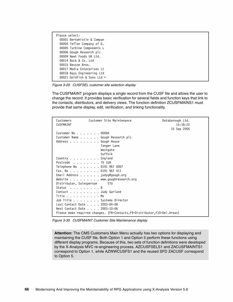
Figure 3-29 CUSFSEL customer site selection display
The CUSFMAINT program displays a single record from the CUSF file and allows the user to change the record. It provides basic verification for several fields and function keys that link to the contacts, distributors, and delivery views. The function definition ZCUSFMAINS1 must provide that same display, edit, verification, and linking functionality.
Figure 3-30 CUSFMAINT Customer Site Maintenance display
Please select: 00001 Bertwhistle & Compan 00004 Teflon Company of G. 00005 Turbine Components L 00006 Gough Research plc 00009 Newt Foods UK Ltd. 00014 Bock & Co. Ltd 00015 Besson Bros. 00017 Media Enterprises Lt 00018 Bays Engineering Ltd 00021 Goldfish & Sons Ltd +
Customers Customer Site Maintenance Databorough Ltd. CUSFMAINT 15:18:22 15 Sep 2005 Customer No . . . . . . . 00006 Customer Name . . . . . . Gough Research plc Address . . . . . . . . . Gough House Tanger Lane Westgate Suffolk Country . . . . . . . . . England Postcode . . . . . . . . T5 1UA Telephone No . . . . . . 0191 967 0007 Fax. No . . . . . . . . . 0191 967 411 Email Address . . . . . . [email protected] Website . . . . . . . . . www.goughresearch.org Distributor, Salesperson STU Status . . . . . . . . . 8 Contact . . . . . . . . . Judy Garland Title . . . . . . . . . . Ms Job Title . . . . . . . . Systems Director Last Contact Date . . . . 2003-04-08 Next Contact Date . . . . 2003-10-06 Please make required changes. (F8=Contacts,F9=Distributor,F10=Del.Areas)
Attention: The CMS Customers Main Menu actually has two options for displaying and maintaining the CUSF file. Both Option 1 and Option 5 perform these functions using different display programs. Because of this, two sets of function definitions were developed by the X-Analysis MVC re-engineering process. AZCUSFSELS1 and ZACUSFMAINTS1 correspond to Option 1, while AZWWCUSFS1 and the reused SFD ZACUSF correspond to Option 5.
66 Modernizing And Improving the Maintainability of RPG Applications using X-Analysis Version 5.6
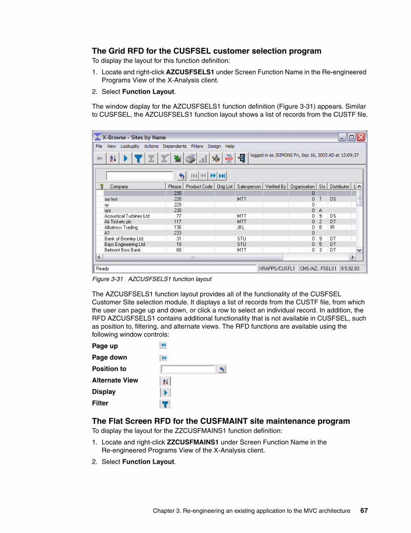
The Grid RFD for the CUSFSEL customer selection programTo display the layout for this function definition:
1. Locate and right-click AZCUSFSELS1 under Screen Function Name in the Re-engineered Programs View of the X-Analysis client.
2. Select Function Layout.
The window display for the AZCUSFSELS1 function definition (Figure 3-31) appears. Similar to CUSFSEL, the AZCUSFSELS1 function layout shows a list of records from the CUSTF file.
Figure 3-31 AZCUSFSELS1 function layout
The AZCUSFSELS1 function layout provides all of the functionality of the CUSFSEL Customer Site selection module. It displays a list of records from the CUSTF file, from which the user can page up and down, or click a row to select an individual record. In addition, the RFD AZCUSFSELS1 contains additional functionality that is not available in CUSFSEL, such as position to, filtering, and alternate views. The RFD functions are available using the following window controls:
Page up
Page down
Position to
Alternate View
Display
Filter
The Flat Screen RFD for the CUSFMAINT site maintenance programTo display the layout for the ZZCUSFMAINS1 function definition:
1. Locate and right-click ZZCUSFMAINS1 under Screen Function Name in the Re-engineered Programs View of the X-Analysis client.
2. Select Function Layout.
Chapter 3. Re-engineering an existing application to the MVC architecture 67

The window display for the ZZCUSFMAINS1 function definition (Figure 3-32) appears. The ZZCUSFMAINS1 provides a single record display that generally follows the same layout as the CUSFMAINT display program.
Figure 3-32 ZZCUSFMAINS1 function layout
Header fieldsThis MVC re-engineering process has assigned the first three fields on the screen to be header fields. These fields will stay at the top of the screen even as the other fields are scrolled.
ValidationThe ZZCUSFMAINS1 RFD is linked to the ZZCUSTFMAIN stored procedure to provide the same business rule validation as the existing display program.
To demonstrate the validation, perform the following steps:
1. Enter BADVALUE in the Telephone No. field.2. Click Validate.3. The status bar shows this message: The telephone no. is invalid.
To review the code that performed this validation, refer to 3.10.3, “Reviewing the re-engineered stored procedure source code” on page 72.
68 Modernizing And Improving the Maintainability of RPG Applications using X-Analysis Version 5.6

Function keysThe function keys from the CUSFMAINT application (F8=Contacts, F9=Distributor, F10=Del.Areas) are implemented as a button bar in the middle of the ZZCUSFMAINS1 window. These buttons are called dependent buttons.
Figure 3-33 ZZCUSFMAINS1 dependent buttons
To demonstrate how the dependent buttons work, click Distributors. The distributor information appears in the lower pane of the ZZCUSFMAINS1 format (Figure 3-34). To return to the detail information, click General.
Figure 3-34 ZZCUSFMAINS1 Distributors dependent button
Chapter 3. Re-engineering an existing application to the MVC architecture 69
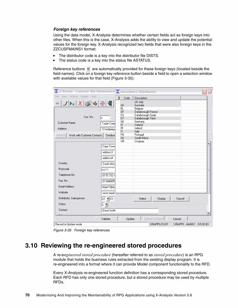
Foreign key referencesUsing the data model, X-Analysis determines whether certain fields act as foreign keys into other files. When this is the case, X-Analysis adds the ability to view and update the potential values for the foreign key. X-Analysis recognized two fields that were also foreign keys in the ZZCUSFMAINS1 format:
� The distributor code is a key into the distributor file DISTS.� The status code is a key into the status file ASTATUS.
Reference buttons are automatically provided for these foreign keys (located beside the field names). Click on a foreign key reference button beside a field to open a selection window with available values for that field (Figure 3-35).
Figure 3-35 Foreign key references
3.10 Reviewing the re-engineered stored proceduresA re-engineered stored procedure (hereafter referred to as stored procedure) is an RPG module that holds the business rules extracted from the existing display program. It is re-engineered into a format where it can provide Model component functionality to the RFD.
Every X-Analysis re-engineered function definition has a corresponding stored procedure. Each RFD has only one stored procedure, but a stored procedure may be used by multiple RFDs.
70 Modernizing And Improving the Maintainability of RPG Applications using X-Analysis Version 5.6
To view the stored procedures in the X-Analysis client, perform the following steps:
1. In the left pane of the X-Analysis client window, locate and expand the CUSTSYS application area under the CMS cross-reference repository.
2. In the expanded CUSTSYS application area, double-click Re-engineered Program & Screens.
The Re-engineered Programs View for the CUSTSYST application area appears in the right window of the of the X-Analysis client (Figure 3-28 on page 64). The stored procedures are shown in the Component Source Member column.
3.10.1 Re-engineered stored procedure naming conventionsEvery X-Analysis stored procedure has a unique name. X-Analysis automatically names each stored procedure when it is generated. X-Analysis adopts a specific naming convention for the re-engineered stored procedure that distinguishes its associated function type and the display program that was the source of its business rules.
The stored procedure name consists of two parts:
� A two-letter identifier based on the function type:
– AZ for Grid Functions (Type A)
– ZZ for Flat Screen Functions (Type Z)
� The existing application display program name. If the program name is longer than eight characters, only the first eight characters are used.
As an example, the stored procedure for the Grid Functions for the ORGMNT application program is named AZORGMNT. The stored procedure for the Flat Screen Functions for the CUS002 application program is named ZZCUS002.
3.10.2 Linking a re-engineered stored procedure to a function definitionStored procedures hold the business rules that the MVC re-engineering process extracted from the display program source. When we run the MVC re-engineering process, it automatically links each re-engineered function definition to the appropriate stored procedure. A function definition can be set to call a stored procedure at the following points:
� Pre-entry� Pre-display� Pre-update� Post-update� Validation� On exit
Tip: Stored procedures can also be reached by double-clicking Functions under the application area. Stored procedures are shown in the Stored Procedure Name column of the Function List View.
Important: Stored procedures are also referred to as shadow programs in the X-Analysis documentation.
Chapter 3. Re-engineering an existing application to the MVC architecture 71
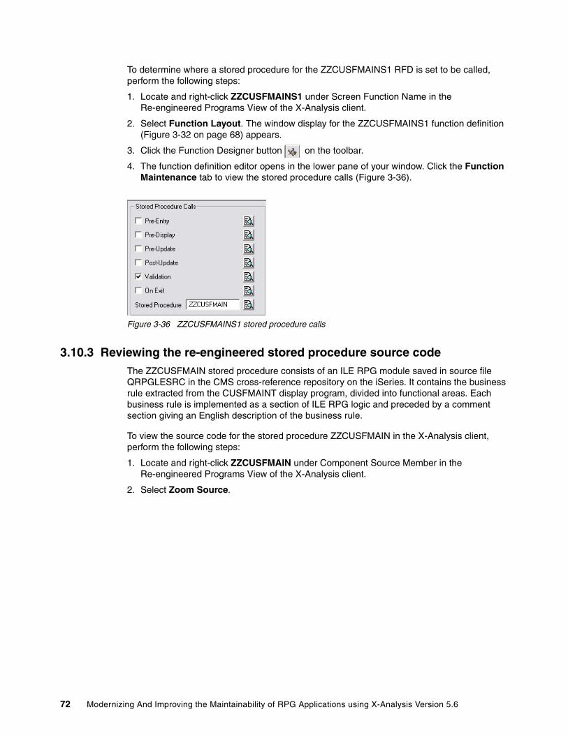
To determine where a stored procedure for the ZZCUSFMAINS1 RFD is set to be called, perform the following steps:
1. Locate and right-click ZZCUSFMAINS1 under Screen Function Name in the Re-engineered Programs View of the X-Analysis client.
2. Select Function Layout. The window display for the ZZCUSFMAINS1 function definition (Figure 3-32 on page 68) appears.
3. Click the Function Designer button on the toolbar.
4. The function definition editor opens in the lower pane of your window. Click the Function Maintenance tab to view the stored procedure calls (Figure 3-36).
Figure 3-36 ZZCUSFMAINS1 stored procedure calls
3.10.3 Reviewing the re-engineered stored procedure source codeThe ZZCUSFMAIN stored procedure consists of an ILE RPG module saved in source file QRPGLESRC in the CMS cross-reference repository on the iSeries. It contains the business rule extracted from the CUSFMAINT display program, divided into functional areas. Each business rule is implemented as a section of ILE RPG logic and preceded by a comment section giving an English description of the business rule.
To view the source code for the stored procedure ZZCUSFMAIN in the X-Analysis client, perform the following steps:
1. Locate and right-click ZZCUSFMAIN under Component Source Member in the Re-engineered Programs View of the X-Analysis client.
2. Select Zoom Source.
72 Modernizing And Improving the Maintainability of RPG Applications using X-Analysis Version 5.6

3. Scroll down to the Validation subroutine to review the validation business rules (Figure 3-37).
Figure 3-37 ZZCUSFMAIN validation code
3.11 Customizing the re-engineered function definitionsThe RFDs AZCUSFSELS1 and ZZCUSFMAINS1 provide the functionality of the existing application programs CUSFSEL and CUSFMAINT. Each RFD requires minor customization to more closely match the existing application display programs. After customization, these RFDs are used in the re-engineered application to provide the same functionality as CUSFSEL and CUSFMAINT.
3.11.1 Customizing the Grid RFDTo customize the Grid RFD AZCUSFSELS1, follow these steps:
1. In the left pane of the X-Analysis client window, locate and expand the CUSTSYS application area under the CMS cross-reference repository.
2. In the expanded CUSTSYS application area, double-click Re-engineered Program & Screens.
Attention: If the existing application display program was written in OPM RPG instead of ILE RPG, the resulting stored procedure will also be in OPM RPG, and will be stored in the QRPGSRC file.
Chapter 3. Re-engineering an existing application to the MVC architecture 73

3. Locate and right-click AZCUSFSELS1 under Screen Function Name in the Re-engineered Programs View of the X-Analysis client.
4. Select Function Layout. The window display for the AZCUSFSELS1 function definition appears.
5. Click the Function Designer button on the toolbar.
6. The function definition editor opens in the lower pane of your window.
7. To change the header text for the customer number, select the Field Layout tab and perform the following steps:
a. Click the row containing CUSF.CUSNO.
b. Enter Customer Number in the column heading field.
8. To add the telephone number and e-mail address to the grid (Figure 3-38).
a. Select the Field Inclusion tab and perform the following steps:
i. Select CUSF.TELNO in the Potential Fields list.
ii. Press the Control key and select CUSTF.USERNM in the Potential Fields list.
iii. Press the Control key and select CUSTF.EMAIL in the Potential Fields list.
iv. Click Add.
Figure 3-38 AZCUSFSELS1 field inclusion
74 Modernizing And Improving the Maintainability of RPG Applications using X-Analysis Version 5.6
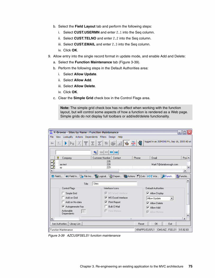
b. Select the Field Layout tab and perform the following steps:
i. Select CUST.USERMN and enter 2.1 into the Seq column.
ii. Select CUST.TELNO and enter 2.2 into the Seq column.
iii. Select CUST.EMAIL and enter 2.3 into the Seq column.
iv. Click OK.
9. Allow entry into the single record format in update mode, and enable Add and Delete:
a. Select the Function Maintenance tab (Figure 3-39).
b. Perform the following steps in the Default Authorities area:
i. Select Allow Update.
ii. Select Allow Add.
iii. Select Allow Delete.
iv. Click OK.
c. Clear the Simple Grid check box in the Control Flags area.
Figure 3-39 AZCUSFSELS1 function maintenance
Note: The simple grid check box has no effect when working with the function layout, but will control some aspects of how a function is rendered as a Web page. Simple grids do not display full toolbars or add/edit/delete functionality.
Chapter 3. Re-engineering an existing application to the MVC architecture 75

10.Add the links for the Customers Main Menu (Figure 3-2 on page 42):
a. Select the Function Menu tab.
b. Add the link for Option 2 - Organisation Maintenance:
i. Click Add Menu Option.
ii. The Add Menu Option dialog box appears. Select Function in the Action field.
iii. Select AZORGMNTS1 (Maintain Organisation) in the Function field.
iv. Click OK.
v. The Menu Properties dialog box appears. Click OK.
c. Add the link for Option 3 - Account Maintenance:
i. Click Add Menu Option.
ii. The Add Menu Option dialog box appears. Select Record in the Action field.
iii. Select ZZCUS002S1 (MAINTAIN ACCOUNTS) in the Function field.
iv. Enter Maintain Accounts in the Caption field.
v. Click OK.
vi. The Menu Properties dialog box appears. Enter 3 in the No of Keys to Prompt field.
vii. Click OK.
d. Add the link for Option 4 - Work with Customer Contacts:
i. Click Add Menu Option.
ii. The Add Menu Option dialog box appears. Select Function in the Action field.
iii. Select AACNTACS (Contacts) in the Function field.
iv. Enter Work with Customer Contacts in the Caption field.
v. Click OK.
vi. The Menu Properties dialog box appears. Click OK.
e. Add the link for Option 6 - Work with Rep. Delivery Areas:
i. Click Add Menu Option.
ii. The Add Menu Option dialog box appears. Select Function in the Action field.
iii. Select AZWWRAREASS1 (Work with Rep. Delivery Areas) in the Function field.
iv. Click OK.
v. The Menu Properties dialog box appears. Click OK.
11.Click Exit to close the function definition editor, and review the final function definition (Figure 3-40 on page 77).
Note: We will not add a link for Option 5 - Work with Customer Sites because this function definition has been customized to replace the functionality originally implemented under that option.
76 Modernizing And Improving the Maintainability of RPG Applications using X-Analysis Version 5.6

Figure 3-40 Final layout for format AZCUSFSELS1
The add, delete, and update functionality can be accessed using the new buttons that appear on the format layout:
Update
Add
Delete
You can click the various buttons to demonstrate how control flows between layouts. Click the Back button on the toolbar to return to the previous window. When you are done reviewing the layout, close the X-Browse - Sites by Name window to return to the X-Analysis client.
3.11.2 Customizing the Flat Screen RFDTo customize the Flat Screen RFD ZZCUSFMAINS1, follow these steps:
1. Locate and right-click ZZCUSFMAINS1 under Screen Function Name in the Re-engineered Programs View of the X-Analysis client.
2. Select Function Layout. The window display for the ZZCUSFMAINS1 function definition appears.
3. Click the Function Designer button on the toolbar.
4. The function definition editor opens in the lower pane of your window. To correct the header text for the customer number, select the Field Layout tab and perform the following steps:
a. Click the row containing the Field CUSF.CUSNO.
b. Enter Customer Number in the Constant / Field Name column.
c. Enter 2 in the Column column.
5. To remove the data display work field, select the Field Inclusion tab and perform the following steps:
a. Select <Work Field>ZZDATE in the Visible Fields list.
Chapter 3. Re-engineering an existing application to the MVC architecture 77

b. Click Remove.
6. To move the address line out of the header, select the Function Maintenance tab and perform the following steps:
a. Enter 3 in the Header Dividing Line No. field.
b. Click OK.
7. To enable add functionality, select the Function Maintenance tab and perform the following steps:
a. Select Allow Add in the Default Authorities group.
b. Click OK.
8. Separate the distributor and salesperson fields: Select the Field Layout tab and perform the following steps:
a. Select the Distributor, Salesperson row.
b. Enter Distributor in the Constant / Field Name column.
c. Select the SINT row.
d. Enter 21 in the row number.
e. Enter 28 in the column number.
f. Click OK.
g. Select the Drag and Drop tab (Figure 3-41) and perform the following steps:
i. Enter 21 in the Row field.
ii. Enter 2 in the Column field.
iii. Enter Salesperson in the New Constant field.
iv. Click Add.
v. Click OK.
Figure 3-41 ZZCUSFMAINS1 Drag and Drop tab
78 Modernizing And Improving the Maintainability of RPG Applications using X-Analysis Version 5.6
9. Add the description field for the distributor and the status code:
a. Select the Field Inclusion tab and perform the following steps:
i. Select ASTATUS.STSTXT in the Potential Fields list.
ii. Press the Control key and select DIST.DNAME in the Potential Fields list.
iii. Click Add.
b. Select the Field Layout tab and perform the following steps:
i. Select the DNAME row.
ii. Enter 14 in the row number.
iii. Enter 35 in the column number.
iv. Select the STSTXT row.
v. Enter 15 in the row number.
vi. Enter 35 in the column number.
vii. Click OK.
viii.Select the Status Text row. Select Delete.
ix. Select the Description row. Select Delete.
x. Click OK.
10.Remove the Work with Distributors dependent button, as the distributor description now shows on the General window. Select the Dependents tab and perform the following steps:
a. Select the ZADISTS function. Select Delete.
b. Click OK.
11.Click Exit to close the function definition editor, and review the final function definition (Figure 3-42 on page 80). When you are through reviewing the layout, close the X-Browse - Site Maintenance window to return to the X-Analysis client.
Chapter 3. Re-engineering an existing application to the MVC architecture 79

Figure 3-42 Final layout for format ZZCUSTFMAINS1
3.12 Web-enabling the application using the X-Web frameworkThe X-Web framework uses the metadata stored in each function definition to manage the View and Controller components. The required Views are built dynamically on demand by X-Web framework. The X-Web framework manages:
� Building each requested View� Flow of control between the Views� Calls to the stored procedures associated with each function definition
You use the X-Web server to execute the re-engineered Web-enabled application. The X-Web server dynamically interprets the standard and re-engineered function definitions, and builds the Web pages as needed. Maintenance changes to the Web pages are implemented by changing the underlying function definition or the configuration setting in the X-Web framework.
80 Modernizing And Improving the Maintainability of RPG Applications using X-Analysis Version 5.6

3.12.1 Starting and configuring the X-Web serverIn order to view and test the Web-enabled application, you must create a test site on the X-Web server, and link to that site to navigate the application. For development purposes, the X-Web server runs on your PC. To correctly set up the X-Web sever to host the sample application, perform the following steps.
1. Select Start → Programs → X-Web → Start X-Web Server to start the X-Web server on your PC.
2. Select Start → Programs → X-Web → Create Site Definition to create a test site definition.
3. In the X-Web Site Administration dialog box (Figure 3-43), click OK.
Figure 3-43 X-Web Site Administration dialog box
Chapter 3. Re-engineering an existing application to the MVC architecture 81

4. In the Basic Site Configurator dialog box (Figure 3-44), perform the following steps in the X-Ref/Application settings area:
a. Select DB400 in the Database Type field.
b. Enter the IP address or domain name of your iSeries in the IP Address field.
c. Enter your iSeries User ID in the User ID field.
d. Enter your iSeries password in the password and confirm password fields.
e. Enter CMS in the Function Library field.
f. Enter your application and data libraries (CMS and XRRAPPS) in the Library List field prior to the existing XREV library.
5. Click Get Eligible Pages in the Entry Page area:
a. On the Site Eligible Pages dialog box, select AZCUSFSELS1 Sites.
b. Click OK.
6. Click the Save button on the toolbar.
Figure 3-44 X-Web Basic Site Configurator dialog box
7. A message box appears with the message cms site Started. Click OK.
8. A message box appears with the message Logged out sucessfully. Click OK.
82 Modernizing And Improving the Maintainability of RPG Applications using X-Analysis Version 5.6

3.12.2 The Web-enabled application Web pagesTo start the Web-enabled application, perform the following steps:
1. Select Start → Programs → X-Web → Test Sites to launch the browser.
2. In the browser window (Figure 3-45), enter your X-Web login information. This is the user ID and password you set up in your site definition. Click Sign In.
Figure 3-45 X-Web login page
Chapter 3. Re-engineering an existing application to the MVC architecture 83

Customer sites maintenance Web pagesWhen you enter the application, the Customer Site Maintenance Selection Web page (Figure 3-46) appears. In the re-engineered application, this page combines the functionality of the Customers Main Menu display program (Figure 2-1 on page 17), the Customer Site Maintenance display program (Figure 2-2 on page 18), and the Work with Customer Sites display program (Figure 2-21 on page 26).
Figure 3-46 Customer Site Maintenance Selection Web page (AZCUSFSELS1)
The Customer Site Maintenance Selection Web page is built from the AZCUSFSELS1 function definition (Figure 3-40 on page 77), which was defined as the entry page for our application when the CMS site definition was created (Figure 3-44 on page 82). The links for the remaining menu items from the Customers Main Menu are displayed at the top of the page under the toolbar.
Tips:
� If the toolbar does not show up on the grid, make sure the function is not defined as a Simple Grid (See 3.11.1, “Customizing the Grid RFD” on page 73 for more information.)
� The page up and page down buttons are formatted to be on the far right side of the screen. If they are not visible, scroll horizontally to bring them into view.
84 Modernizing And Improving the Maintainability of RPG Applications using X-Analysis Version 5.6

In the selection window, click on the Company text of an individual record to bring up a single record display (Figure 3-47).
Figure 3-47 Customer Site Maintenance Single Record Web page (ZZCUSFMAINS1)
The Customer Site Maintenance Single Record Web page is built from the ZZCUSFMAINS1 function definition (Figure 3-42 on page 80). It corresponds to the single record site display in the existing application (Figure 2-4 on page 19). The toolbar buttons give access to the edit and delete functions. Record validations are handled by the stored procedure ZZCUSFMAIN.
Click the Back button in your Web browser or the List button on the toolbar to return to the Customer Site Maintenance Selection Web page.
Attention: When you worked with a grid function displayed in the function layout, you could click anywhere in a grid row to access the single record display. However, when working with a grid function displayed on a Web page, the link behavior more closely follows the hyperlink standard. Only the actual text in the first column acts as a link to the single record format. If you click elsewhere in the row, it will have no effect.
Chapter 3. Re-engineering an existing application to the MVC architecture 85
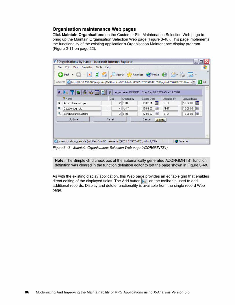
Organisation maintenance Web pagesClick Maintain Organisations on the Customer Site Maintenance Selection Web page to bring up the Maintain Organisation Selection Web page (Figure 3-48). This page implements the functionality of the existing application’s Organisation Maintenance display program (Figure 2-11 on page 22).
Figure 3-48 Maintain Organisations Selection Web page (AZORGMNTS1)
As with the existing display application, this Web page provides an editable grid that enables direct editing of the displayed fields. The Add button on the toolbar is used to add additional records. Display and delete functionality is available from the single record Web page.
Note: The Simple Grid check box of the automatically generated AZORGMNTS1 function definition was cleared in the function definition editor to get the page shown in Figure 3-48.
86 Modernizing And Improving the Maintainability of RPG Applications using X-Analysis Version 5.6

Click the View button beside a record to view the single record Web page (Figure 3-49).
Figure 3-49 Maintain Organisations Single Record Web page (ZAORGS)
The Maintain Organisations Single Record Web page is built from the standard function definition ZAORGS that was automatically created during the data modeling process. This provides the add and delete functionality of the existing application single record screen (Figure 2-12 on page 22).
Click the Back button in your browser once to return to the Maintain Organisation Selection Web page, and a second time to return to the Customer Site Maintenance Selection Web page.
Account maintenance Web pagesClick Maintain Accounts on the Customer Site Maintenance Selection Web page to bring up the Account Maintenance Web pages. These Web pages implement the functionality of the existing application’s Account Maintenance display program. Unlike the other options, the account maintenance screen does not start with a selection screen. Instead, it prompts for three key fields (Figure 2-14 on page 23), and then displays the record directly associated with those key fields (Figure 2-15 on page 23).
Note: Some minor customizations with the function definition editor were made to the automatically generated ZAORGS function definition to achieve the page in Figure 3-49:
� The default function menu items were removed.� The default dependent view for related sites was removed.� The update functionality was removed.
Chapter 3. Re-engineering an existing application to the MVC architecture 87
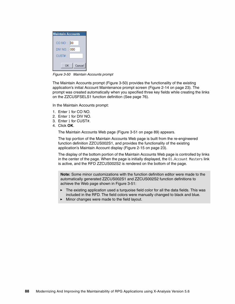
Figure 3-50 Maintain Accounts prompt
The Maintain Accounts prompt (Figure 3-50) provides the functionality of the existing application’s initial Account Maintenance prompt screen (Figure 2-14 on page 23). The prompt was created automatically when you specified three key fields while creating the links on the ZZCUSFSELS1 function definition (See page 76).
In the Maintain Accounts prompt:
1. Enter 1 for CO NO.2. Enter 1 for DIV NO.3. Enter 1 for CUST#. 4. Click OK.
The Maintain Accounts Web page (Figure 3-51 on page 89) appears.
The top portion of the Maintain Accounts Web page is built from the re-engineered function definition ZZCUS002S1, and provides the functionality of the existing application’s Maintain Account display (Figure 2-15 on page 23).
The display of the bottom portion of the Maintain Accounts Web page is controlled by links in the center of the page. When the page is initially displayed, the 01.Account Masters link is active, and the RFD ZZCUS002S2 is rendered on the bottom of the page.
Note: Some minor customizations with the function definition editor were made to the automatically generated ZZCUS002S1 and ZZCUS002S2 function definitions to achieve the Web page shown in Figure 3-51:
� The existing application used a turquoise field color for all the data fields. This was included in the RFD. The field colors were manually changed to black and blue.
� Minor changes were made to the field layout.
88 Modernizing And Improving the Maintainability of RPG Applications using X-Analysis Version 5.6

Figure 3-51 Maintain Accounts Web page (ZZCUS002S1)
5. Select 02.Account Masters 2 to render the ZZCUS002S3 RFD on the bottom of the Maintain Accounts Web page. Select 03.Customer Tax Codes to render the ZZCUS002S4 RFD on the bottom of the Maintain Accounts Web page. These RFDs correspond to the additional screens of the existing application’s Account Maintenance display program.
6. Click the Back button in your Web browser until you return to the Customer Site Maintenance Selection Web page.
Chapter 3. Re-engineering an existing application to the MVC architecture 89

Work with Customer Contacts Web pagesClick Work with Customer Contacts on the Customer Site Maintenance Selection Web page to open the Customer Contacts Selection Web page (Figure 3-52). This page implements the functionality of the existing application’s Work with Customer Contacts display program.
Figure 3-52 Customer Contacts Selection Web page (AACNTACS)
The Customer Contacts Selection Web page is built from the standard function definition AACNTACS that was customized previously (Figure 3-16 on page 54). This provides the functionality of the existing application subfile selection screens (Figure 2-17 on page 24 and Figure 2-18 on page 25).
In the selection window, click on the Customer Number text of an individual record.
90 Modernizing And Improving the Maintainability of RPG Applications using X-Analysis Version 5.6
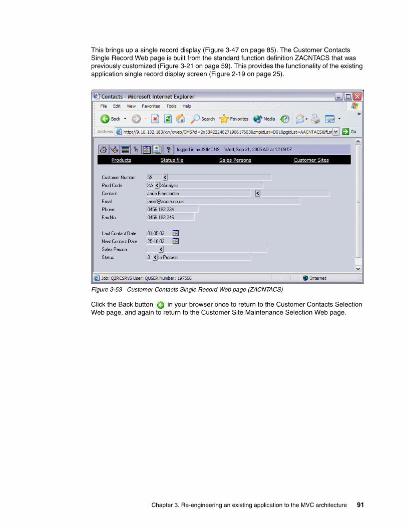
This brings up a single record display (Figure 3-47 on page 85). The Customer Contacts Single Record Web page is built from the standard function definition ZACNTACS that was previously customized (Figure 3-21 on page 59). This provides the functionality of the existing application single record display screen (Figure 2-19 on page 25).
Figure 3-53 Customer Contacts Single Record Web page (ZACNTACS)
Click the Back button in your browser once to return to the Customer Contacts Selection Web page, and again to return to the Customer Site Maintenance Selection Web page.
Chapter 3. Re-engineering an existing application to the MVC architecture 91

Work with Rep. Delivery Areas Web pagesClick Work with Rep. Delivery Areas on the Customer Site Maintenance Selection Web page to bring up the Delivery Areas Selection Web page (Figure 3-54). This Web page implements the functionality of the existing application’s Work with Rep. Delivery Areas display program.
The Delivery Areas Selection Web page is built from the re-engineered function definition AZWWRAREASS1. This provides the functionality of the existing application selection list (Figure 2-26 on page 29).
Figure 3-54 Delivery Areas Selection Web page (AZWWRAREASS1)
Click an individual record in the selection window to bring up a single record display (Figure 3-55). The Delivery Areas Single Record Web page is built from the standard function definition ZADELIVA. This provides the functionality of the existing application single record display screen (Figure 2-28 on page 29).
Figure 3-55 Delivery Areas single record Web page (ZADELIVA)
Click the Back button in your Web browser once to return to the Delivery Areas selection Web page, and a second time to return to the Customer Site Maintenance selection Web page.
92 Modernizing And Improving the Maintainability of RPG Applications using X-Analysis Version 5.6

3.13 Implementing the Web-enabled application in JavaThe recommended approach is to leave as much of the application user interface as interpreted metadata as possible. This helps ensure uniformity of styles and simplifies maintenance.
When greater control over part or all of the user interface portion of the Web-enabled application is required, selected standard and re-engineered function definitions are implemented using JavaServer Faces (JSF) technology.
We use X-Analysis to generate standard Java components (JavaServer Faces, JavaBeans, and Java abstract classes) in WDSc from the MVC re-engineered application’s function definitions. These components can be edited or further customized in a Java development environment such as WDSc.
3.13.1 Java componentsThe X-Analysis JSF Generator (Figure 3-56) creates the standard Java components needed to implement a function definition in the form of JavaServer Faces (JSF), JavaBeans, and Java abstract classes. For documentation purposes, the correct tags are generated in the JavaBeans to allow export into Unified Modeling Language (UML).
Figure 3-56 JSF Generator
JavaServer FacesJavaServer Faces (JSF) is a standardized specification for developing Web applications with rich user interfaces. JSF technology is a user interface framework for building Java-based Web applications that run on the server side and render the user interface back to the client. One of the advantages of the JSF specification is that it is based on the Model View Controller (MVC) architecture, which offers a clean separation between presentation and logic. For more information about JavaServer Faces, refer to:
http://java.sun.com/j2ee/javaserverfaces
JavaBeansJavaBeans technology is the component architecture for the Java 2 Platform, Standard Edition (J2SE™). JavaBeans are reusable software programs (components) that you can develop and assemble easily to create sophisticated applications. For more information about JavaBeans, refer to:
http://java.sun.com/products/javabeans/index.jsp
Function Definitions(View – Controller)
JSFCode JavaBeans
JSFGenerator
Chapter 3. Re-engineering an existing application to the MVC architecture 93

Java abstract classesA Java abstract class is a class description that can never be instantiated into a specific object. Abstract classes are created so that other classes can inherit from them and implement their abstract methods. The first time an MVC re-engineering project is instanced in WebSphere, X-Analysis creates a set of Java abstract classes to provide functionality needed by the View-Controller components to provide database access and stored procedure calls. These Java abstract classes are shared between all of the WebSphere projects.
Unified Modeling LanguageThe Unified Modeling Language (UML) is an Object Management Group specification, to pattern application structure, behavior, and architecture, as well as business process and data structure. X-Analysis places the correct tags into the JavaBeans it creates to allow export into a UML format. The UML-formatted information can be used to build standard Java documentation. For more information about UML, refer to:
http://www.uml.org/
3.13.2 Generating the Java componentsWe have selected the Customer Site Maintenance Single Record Web page (Figure 3-47 on page 85) to be implemented as Java components. This Web page is currently being created interactively from the ZZCUSFMAINS1 re-engineered function definition by the X-Web framework. To generate the Java components for this function definition, perform these steps:
1. In the left pane of the X-Analysis client window, locate and expand the CUSTSYS application area under the CMS cross-reference repository and double-click Re-engineered Program & Screens.
2. Locate and right-click ZZCUSFMAINS1 under Screen Function Name in the Re-engineered Programs View of the X-Analysis client.
3. Select Generate JSF, Javabean(s) and UML (Figure 3-57).
Figure 3-57 Generating JSF for RFD ZZCUSFMAINS1
94 Modernizing And Improving the Maintainability of RPG Applications using X-Analysis Version 5.6

4. The Generate Web Pages dialog box (Figure 3-58) appears with the message Cms project has not been configured in WebSphere Studio. Click Configure.
Figure 3-58 Generate Web Pages configuration dialog box
5. If you are currently running the X-Web Server on your PC, you may be prompted to stop it. Select Start → Programs → X-Web → Stop X-Web Server to stop the X-Web server.
6. The WebSphere Studio Site Developer (WSSD) will be started on your PC. This may take some time. WSSD displays a splash screen and is then minimized on your task bar.
7. The Generate Web Pages dialog box (Figure 3-58) appears with the message Process completed. Click OK.
Figure 3-59 Generate Web Pages process complete dialog box
Note: WDSc is an extension to WSSD. When the WebSphere client is started automatically from X-Analysis, the splash screen and title bar read WebSphere Studio Site Developer (Windows). When you start the WebSphere client independently (Start → Programs → IBM WebSphere Studio → Development Studio Client for iSeries 5.1.2), the splash screen and title bar will read WebSphere Development Studios Client for iSeries. For the purpose of this chapter, the WebSphere client can be started by either method. For more information about the relationship between the WebSphere Studio Site Developer and the WebSphere Development Studios Client for iSeries, refer to WebSphere Development Studio Client for iSeries Version 5.1.2, SG24-6961.
Chapter 3. Re-engineering an existing application to the MVC architecture 95
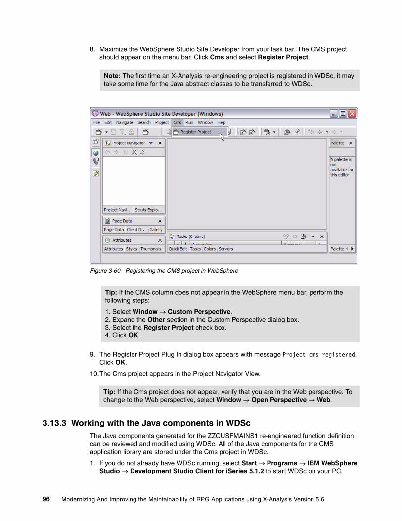
8. Maximize the WebSphere Studio Site Developer from your task bar. The CMS project should appear on the menu bar. Click Cms and select Register Project.
Figure 3-60 Registering the CMS project in WebSphere
9. The Register Project Plug In dialog box appears with message Project cms registered. Click OK.
10.The Cms project appears in the Project Navigator View.
3.13.3 Working with the Java components in WDScThe Java components generated for the ZZCUSFMAINS1 re-engineered function definition can be reviewed and modified using WDSc. All of the Java components for the CMS application library are stored under the Cms project in WDSc.
1. If you do not already have WDSc running, select Start → Programs → IBM WebSphere Studio → Development Studio Client for iSeries 5.1.2 to start WDSc on your PC.
Note: The first time an X-Analysis re-engineering project is registered in WDSc, it may take some time for the Java abstract classes to be transferred to WDSc.
Tip: If the CMS column does not appear in the WebSphere menu bar, perform the following steps:
1. Select Window → Custom Perspective.2. Expand the Other section in the Custom Perspective dialog box.3. Select the Register Project check box.4. Click OK.
Tip: If the Cms project does not appear, verify that you are in the Web perspective. To change to the Web perspective, select Window → Open Perspective → Web.
96 Modernizing And Improving the Maintainability of RPG Applications using X-Analysis Version 5.6
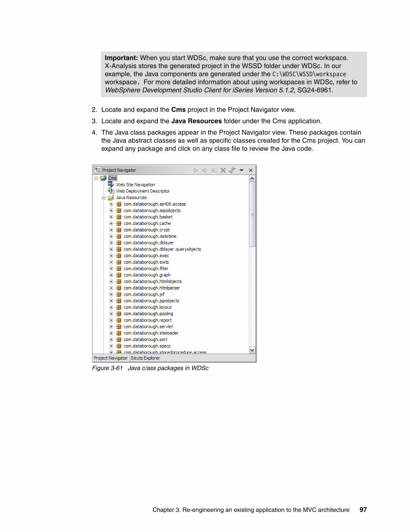
2. Locate and expand the Cms project in the Project Navigator view.
3. Locate and expand the Java Resources folder under the Cms application.
4. The Java class packages appear in the Project Navigator view. These packages contain the Java abstract classes as well as specific classes created for the Cms project. You can expand any package and click on any class file to review the Java code.
Figure 3-61 Java c/ass packages in WDSc
Important: When you start WDSc, make sure that you use the correct workspace. X-Analysis stores the generated project in the WSSD folder under WDSc. In our example, the Java components are generated under the C:\WDSC\WSSD\workspace workspace. For more detailed information about using workspaces in WDSc, refer to WebSphere Development Studio Client for iSeries Version 5.1.2, SG24-6961.
Chapter 3. Re-engineering an existing application to the MVC architecture 97

5. Scroll down in the Project Navigator view and expand the jsf folder. In this folder, you will see the JSFs for your application. Double-click zzcusfmains1.jsp to open it in the Edit view (Figure 3-62).
Figure 3-62 zzcusfmains1.jsp
6. The JSF is fully editable in the design mode. For the example project, we simply change the font attributes for the Customer number and name:
a. To change the Customer Number font attributes, perform the following steps:
i. Click the CUSNO text box.
ii. Click the Attributes view.
iii. Enter background-color: transparent; font-size: 12pt; font-weight: bold in the Properties field.
b. To change the Customer Name font attributes, perform the following steps:
i. Click the CNAME text box.
ii. Click the Attributes view.
iii. Enter background-color: transparent; font-size: 12pt; font-weight: bold in the Properties field.
iv. Enter 30 in the Width field.
c. Select File → Save to save the changes (Figure 3-63 on page 99).
98 Modernizing And Improving the Maintainability of RPG Applications using X-Analysis Version 5.6

Figure 3-63 zzcusfmains1.jsp after changes
3.13.4 Viewing the application JSFThe JSF created for the ZZCUSFMAINS1 re-engineered function definition is now available for use by the X-Web server. To view the application:
1. Select Start → Programs → X-Web → Start X-Web Server to start the X-Web server on your PC.
2. Select Start → Programs → X-Web → Test Sites to launch the browser.
3. In the browser window (Figure 3-45 on page 83), enter your X-Web login information. This is the user ID and password you set up in your site definition. Click Sign In.
4. When you enter the application, the Customer Site Maintenance selection Web page (Figure 3-46 on page 84) appears. Click an individual record in the selection window to bring up the Customer Site Single Record Web page (Figure 3-64 on page 100).
Chapter 3. Re-engineering an existing application to the MVC architecture 99

Figure 3-64 Customer Site Single Record Web page (JSF)
Once again, you can test the validation logic:
1. Click the Edit button on the toolbar.
Tip: The browser title bar indicates whether the page being displayed was built from a function definition or a JSF. Web pages built from a JSF have the text (JSF) included after the function name in the title bar.
100 Modernizing And Improving the Maintainability of RPG Applications using X-Analysis Version 5.6

2. Enter BADVALUE in the Telephone No. field and click Update. The JSF reflects the appropriate error message (Figure 3-65).
Figure 3-65 JSF validation example
Chapter 3. Re-engineering an existing application to the MVC architecture 101
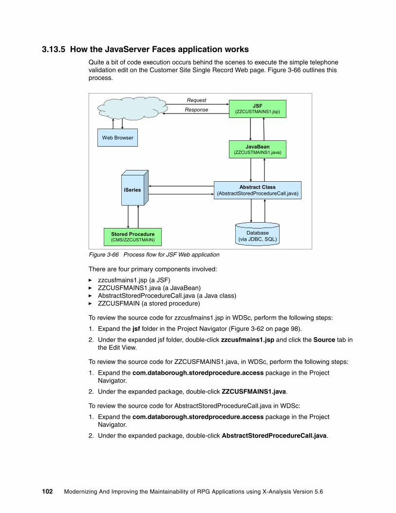
3.13.5 How the JavaServer Faces application worksQuite a bit of code execution occurs behind the scenes to execute the simple telephone validation edit on the Customer Site Single Record Web page. Figure 3-66 outlines this process.
Figure 3-66 Process flow for JSF Web application
There are four primary components involved:
� zzcusfmains1.jsp (a JSF)� ZZCUSFMAINS1.java (a JavaBean)� AbstractStoredProcedureCall.java (a Java class)� ZZCUSFMAIN (a stored procedure)
To review the source code for zzcusfmains1.jsp in WDSc, perform the following steps:
1. Expand the jsf folder in the Project Navigator (Figure 3-62 on page 98).
2. Under the expanded jsf folder, double-click zzcusfmains1.jsp and click the Source tab in the Edit View.
To review the source code for ZZCUSFMAINS1.java, in WDSc, perform the following steps:
1. Expand the com.databorough.storedprocedure.access package in the Project Navigator.
2. Under the expanded package, double-click ZZCUSFMAINS1.java.
To review the source code for AbstractStoredProcedureCall.java in WDSc:
1. Expand the com.databorough.storedprocedure.access package in the Project Navigator.
2. Under the expanded package, double-click AbstractStoredProcedureCall.java.
Request
Response
Database(via JDBC, SQL)
Web Browser
iSeries
Stored Procedure(CMS/ZZCUSTMAIN)
JSF(ZZCUSTMAINS1.jsp)
JavaBean(ZZCUSTMAINS1.java)
Abstract Class(AbstractStoredProcedureCall.java)
102 Modernizing And Improving the Maintainability of RPG Applications using X-Analysis Version 5.6

To review the source code for ZZCUSFMAIN in WDSc, do the following steps:
1. Switch to the Remote System Explorer perspective (Window → Open Perspective → Remote System Explorer).
2. Expand the QRPGLESRC file under the CMS library in the User Library folder for your iSeries. Under the QRPGLESRC file, double-click ZZCUSFMAIN.
Processing the update requestAn update record request comes from the Customer Site Single Record Web page in the Web browser and is routed to the JSF that is used to display and accept input for that Web page.
The JSF module (zzcusfmains1.jsp) receives the update record request from the browser and responds by calling the update method of its associated JavaBean (ZZCUSTFMAINS1.java) (Example 3-1).
Example 3-1 Call update method of zzcusfmains1.java
jsp:useBean id="zzcusfmains1" class="com.databorough.storedprocedure.access.ZZCUSFMAINS1" scope="session" />........
else if (request.getParameter("updRec.x") != null)
{// Update the datazzcusfmains1.update();
}
The class ZZCUSFMAINS1 in the JavaBean ZZCUSFMAINS1.java extends the AbstractStoredProcedureCall class (Example 3-2).
Example 3-2 Class ZZCUSFMAINS1.java
package com.databorough.storedprocedure.access;
/** * Insert the type's description here. * Creation date: (09/22/05 01:30:48 PM) * @author: Amit Arya */import com.ibm.as400.access.AS400;
public class ZZCUSFMAINS1 extends AbstractStoredProcedureCall{
As the Java class ZZCUSFMAINS1 does not implement the update method, we look to its super class AbstractStoredProcedureCall for the implementation details.
The update method of the AbstractStoredProcedureCall invokes the call method to implement the stored procedure call (Example 3-3).
Example 3-3 Invoke stored procedure call
public abstract class AbstractStoredProcedureCall implements ActionListener{....../** * Updates the data. * @version: (6/25/2004 4:30:49 PM * @return boolean
Chapter 3. Re-engineering an existing application to the MVC architecture 103
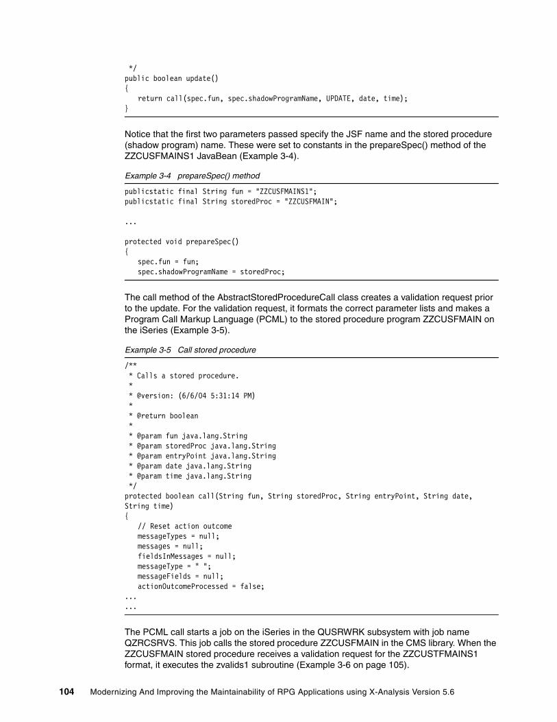
*/public boolean update(){
return call(spec.fun, spec.shadowProgramName, UPDATE, date, time);}
Notice that the first two parameters passed specify the JSF name and the stored procedure (shadow program) name. These were set to constants in the prepareSpec() method of the ZZCUSFMAINS1 JavaBean (Example 3-4).
Example 3-4 prepareSpec() method
publicstatic final String fun = "ZZCUSFMAINS1";publicstatic final String storedProc = "ZZCUSFMAIN";
...
protected void prepareSpec(){
spec.fun = fun;spec.shadowProgramName = storedProc;
The call method of the AbstractStoredProcedureCall class creates a validation request prior to the update. For the validation request, it formats the correct parameter lists and makes a Program Call Markup Language (PCML) to the stored procedure program ZZCUSFMAIN on the iSeries (Example 3-5).
Example 3-5 Call stored procedure
/** * Calls a stored procedure. * * @version: (6/6/04 5:31:14 PM) * * @return boolean * * @param fun java.lang.String * @param storedProc java.lang.String * @param entryPoint java.lang.String * @param date java.lang.String * @param time java.lang.String */protected boolean call(String fun, String storedProc, String entryPoint, String date, String time){
// Reset action outcomemessageTypes = null;messages = null;fieldsInMessages = null;messageType = " ";messageFields = null;actionOutcomeProcessed = false;
...
...
The PCML call starts a job on the iSeries in the QUSRWRK subsystem with job name QZRCSRVS. This job calls the stored procedure ZZCUSFMAIN in the CMS library. When the ZZCUSFMAIN stored procedure receives a validation request for the ZZCUSTFMAINS1 format, it executes the zvalids1 subroutine (Example 3-6 on page 105).
104 Modernizing And Improving the Maintainability of RPG Applications using X-Analysis Version 5.6

Example 3-6 Execute subroutine - zvalids1
C* VALIDATION C when entrypoint = 'VALIDATION' C select C when callingfun = 'ZZCUSFMAINS1' C exsr zvalids1
The zvalids1 subroutine contains a business rule to validate that the telephone number consists of any combination of digits or blanks (Example 3-7).
Example 3-7 Validate telephone number
C* Business Rule No. XRAPPS/QRPGLESRC/CUSFMAINT/211 Validation. C* V00002 CUSF TELNO The telephone no. is invalid. C* If the field "Phone" is not blank , verify the field "Phone" againC* 0123456789'. If other values found then the field "Phone" is invalC* Telephone number C if TELNO <> *blanks C ' 0123456789' check TELNO z1 C if %found C* Return message: "The telephone no. is invalid." C eval n1 = n1 + 1 C if n1 <= 20 C eval rtnflds(n1) = 'TELNO' C eval rtnmsgids(n1) = 'OEM0014' C eval rtnmsgtp = 'E' C endif C endif
When the validation fails, the error message is sent back as part of the response. The AbstractStoredProcedureCall class aborts the update request and passes the message back to the JSF zzcusfmains1.jsp for display in the browser.
If the validation had been processed sucessfully, the AbstractStoredProcedureCall class would have constructed an SQL statement and executed it against the iSeries database to update the CUSF file.
Stored procedure ZZCUSFMAINExample 3-8 gives the full text for the ZZCUSFMAIN stored procedure.
Example 3-8 Stored procedure ZZCUSFMAIN
H*?-------------------------------------------------------------------- H*?COPYRIGHT DATABOROUGH LTD 2005 H*? H*?PROGRAM: Shadow Program for ZZCUSFMAINS1 H*?AUTHOR: Databorough Ltd. H*?VERSION: No: 1.00 Date: 23/09/2005 Time: 15:52:03 H*?-------------------------------------------------------------------- H debug(*yes) Fdists if e k disk
Tip: The job invoked by the PCML call to the iSeries can be viewed from an iSeries command line using the WRKACTJOB command. The job name/user ID will always be QZRCSRVS/QUSER. The job number can be found in the status bar of the JSF Web page (see Figure 3-65 on page 101). The stored procedure can be debugged using the STRSRVJOB command or the iterative debugger found in WDSc.
Chapter 3. Re-engineering an existing application to the MVC architecture 105

D********************************************************************** D*?D e f i n i t i o n s D********************************************************************** D*?*ENTRY parameters:- D*?Job values D inuser s 10 D indate s 8 D intime s 6 D*?Action required (ADD/UPDATE/DELETE/DISPLAY) D action s 10 D*?Entry point D entrypoint s 20 D*?21 X 3000 bytes of data representing a single record for each of the D*?primary physical file & upto 20 secondary files D indbf s 3000 dim(21) D*?Return message type D rtnmsgtp s 1 D*?Array for return messages D rtnmsg s 80 dim(20) D*?Array for return messages ids D rtnmsgids s 7 dim(20) D*?Array for the fields to which messages relate D rtnflds s 30 dim(20) D*?Flag to indicate if fields have been updated D rtnupdbuf s 1 D*?New function name for PREENTRY processing D rtnnewfun s 20 D*?Further fields D gtots s 30p 9 D zworkflds s 50a dim(20) D zwfnames s 30a dim(20) D zwftypes s 1a dim(20) D*?Supressed fields: D supflds s 30 dim(20) D*?Fields to be displayed as constants: D conflds s 30 dim(20) D*?Fields with overriden colors: D clrflds s 30 dim(20) D*?Overriden colors: D ovrclrs s 3 dim(20)
D*?Calling function (passed in rtnnewfun field) D callingfun s 20a
D*?Work fields D n1 s 5p 0 D z1 s 5p 0 D statuses s 1a dim(37) ctdata perrcd(37) CMD Key Data
D*?Format file data
D*?FILE NAME d CUSF e ds extname(CUSF)
C********************************************************************** C*?M a i n l i n e C o d e C********************************************************************** C*?Format file records
106 Modernizing And Improving the Maintainability of RPG Applications using X-Analysis Version 5.6

C eval CUSF = indbf(001)
C*?Process individual entry points etc C select
C*?PREDISPLAY C when entrypoint = 'PREDISPLAY' C exsr zpredisp C*?VALIDATION C when entrypoint = 'VALIDATION' C select C when callingfun = 'ZZCUSFMAINS1' C exsr zvalids1 C endsl C*?PREUPDATE C when entrypoint = 'PREUPDATE ' C exsr zpreupd C*?POSTUPDATE C when entrypoint = 'POSTUPDATE' C exsr zpostupd C*?PREENTRY C when entrypoint = 'PREENTRY' C exsr zpreentry C*?ONEXIT C when entrypoint = 'ONEXIT' C exsr zonexit C*?CALL TO EXIT PROGRAM C when action = 'CALL' C exsr zcallexp
C endsl
C*?Update buffers if necessary C if rtnupdbuf = 'Y' C eval indbf(001) = CUSF C endif
C*?Perform Termination Routines C eval *inlr = *on C return C********************************************************************** C*?L o g i c a l E n d o f P r o g r a m C**********************************************************************
C********************************************************************** C*?PREDISPLAY C********************************************************************** C zpredisp begsr C endsr C**********************************************************************
C********************************************************************** C*?VALIDATION C********************************************************************** C zvalids1 begsr?%!BRC* Business Rule No. XRAPPS/QRPGLESRC/CUSFMAINT/202 Validation.?@!BRC* V00001 CUSF CNAME You must enter the customer name.?=!BRC* If the field "Company" is blank then it is invalid. C*?Customer name C if CNAME = *blanks
Chapter 3. Re-engineering an existing application to the MVC architecture 107

C* Return message: "You must enter the customer name." C eval n1 = n1 + 1 C if n1 <= 20 C eval rtnflds(n1) = 'CNAME' C eval rtnmsgids(n1) = 'OEM0012' C eval rtnmsgtp = 'E' C endif C endif?%!BRC* Business Rule No. XRAPPS/QRPGLESRC/CUSFMAINT/211 Validation.?@!BRC* V00002 CUSF TELNO The telephone no. is invalid.?=!BRC* If the field "Phone" is not blank , verify the field "Phone" against '?=!BRC* 0123456789'. If other values found then the field "Phone" is invalid. C*?Telephone number C if TELNO <> *blanks C ' 0123456789' check TELNO z1 C if %found C* Return message: "The telephone no. is invalid." C eval n1 = n1 + 1 C if n1 <= 20 C eval rtnflds(n1) = 'TELNO' C eval rtnmsgids(n1) = 'OEM0014' C eval rtnmsgtp = 'E' C endif C endif C endif?%!BRC* Business Rule No. XRAPPS/QRPGLESRC/CUSFMAINT/223 Validation.?@!BRC* V00003 CUSF FAXNO The fax. no. is invalid.?=!BRC* If the field "Fax. No." is not blank , verify the field "Fax. No."?=!BRC* against ' 0123456789'. If other values found then the field "Fax. No."?=!BRC* is invalid. C*?Fax number C if FAXNO <> *blanks C ' 0123456789' check FAXNO z1 C if %found C* Return message: "The fax. no. is invalid." C eval n1 = n1 + 1 C if n1 <= 20 C eval rtnflds(n1) = 'FAXNO' C eval rtnmsgids(n1) = 'OEM0015' C eval rtnmsgtp = 'E' C endif C endif C endif?%!BRC* Business Rule No. XRAPPS/QRPGLESRC/CUSFMAINT/235 Validation.?@!BRC* V00004 CUSF DSDCDE The distributor is invalid.?=!BRC* If the field "Distributor" is not blank , verify the field "Distributor"?=!BRC* against the file "Distributors". If not on file then the field?=!BRC* "Distributor" is invalid. C*?Distributor C if DSDCDE <> *blanks C DSDCDE setll(e) rprods C if not %equal(dists) C* Return message: "The distributor is invalid." C eval n1 = n1 + 1 C if n1 <= 20 C eval rtnflds(n1) = 'DSDCDE' C eval rtnmsgids(n1) = 'OEM0018' C eval rtnmsgtp = 'E' C endif C endif
108 Modernizing And Improving the Maintainability of RPG Applications using X-Analysis Version 5.6

C endif?%!BRC* Business Rule No. XRAPPS/QRPGLESRC/CUSFMAINT/247 Validation.?@!BRC* V00005 CUSF STATUS The status is invalid.?=!BRC* If the field "Sts" is not blank , set the field Z1 to 1 , verify the?=!BRC* field "Sts" against the array STATUSES from Z1. If not found then the?=!BRC* field "Sts" is invalid. C*?Status C if STATUS <> *blanks C eval z1 = 1 C STATUS lookup statuses(z1) 77 C if not %found C* Return message: "The status is invalid." C eval n1 = n1 + 1 C if n1 <= 20 C eval rtnflds(n1) = 'STATUS' C eval rtnmsgids(n1) = 'OEM0019' C eval rtnmsgtp = 'E' C endif C endif C endif?%!BRC* Business Rule No. XRAPPS/QRPGLESRC/CUSFMAINT/260 Validation.?@!BRC* V00006 CUSF USERNM You must enter a contact name.?=!BRC* If the field "Contact" is blank then it is invalid. C*?Contact C if USERNM = *blanks C* Return message: "You must enter a contact name." C eval n1 = n1 + 1 C if n1 <= 20 C eval rtnflds(n1) = 'USERNM' C eval rtnmsgids(n1) = 'OEM0020' C eval rtnmsgtp = 'E' C endif C endif?%!BRC* Business Rule No. XRAPPS/QRPGLESRC/CUSFMAINT/269 Validation.?@!BRC* V00007 CUSF SALUT The title is invalid.?=!BRC* If the field "Salutation" is not blank. If the field "Salutation" is not?=!BRC* 'Mr' and the field "Salutation" is not 'Mrs' and the field "Salutation"?=!BRC* is not 'Ms' and the field "Salutation" is not 'Dr' and the field?=!BRC* "Salutation" is not 'Doctor' and the field "Salutation" is not?=!BRC* 'Professor' and the field "Salutation" is not 'Sir' and the field?=!BRC* "Salutation" is not 'Lord' and the field "Salutation" is not 'Lady' then?=!BRC* the field "Salutation" is invalid. C*?Title C if SALUT <> *blanks C if SALUT <> 'Mr' C and SALUT <> 'Mrs' C and SALUT <> 'Ms' C and SALUT <> 'Dr' C and SALUT <> 'Doctor' C and SALUT <> 'Professor' C and SALUT <> 'Sir' C and SALUT <> 'Lord' C and SALUT <> 'Lady' C* Return message: "The title is invalid." C eval n1 = n1 + 1 C if n1 <= 20 C eval rtnflds(n1) = 'SALUT' C eval rtnmsgids(n1) = 'OEM0021' C eval rtnmsgtp = 'E' C endif
Chapter 3. Re-engineering an existing application to the MVC architecture 109
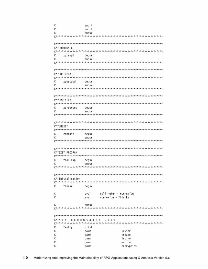
C endif C endif C endsr C**********************************************************************
C********************************************************************** C*?PREUPDATE C********************************************************************** C zpreupd begsr C endsr C**********************************************************************
C********************************************************************** C*?POSTUPDATE C********************************************************************** C zpostupd begsr C endsr C**********************************************************************
C********************************************************************** C*?PREENTRY C********************************************************************** C zpreentry begsr C endsr C**********************************************************************
C********************************************************************** C*?ONEXIT C********************************************************************** C zonexit begsr C endsr C**********************************************************************
C********************************************************************** C*?EXIT PROGRAM C********************************************************************** C zcallexp begsr C endsr C**********************************************************************
C********************************************************************** C*?Initialisation C********************************************************************** C *inzsr begsr
C eval callingfun = rtnnewfun C eval rtnnewfun = *blanks
C endsr C**********************************************************************
C********************************************************************** C*?N o n - e x e c u t a b l e C o d e C********************************************************************** C *entry plist C parm inuser C parm indate C parm intime C parm action C parm entrypoint
110 Modernizing And Improving the Maintainability of RPG Applications using X-Analysis Version 5.6

C parm indbf C parm rtnmsgtp C parm rtnmsg C parm rtnmsgids C parm rtnflds C parm rtnupdbuf C parm rtnnewfun C parm gtots C parm zworkflds C parm zwfnames C parm zwftypes C parm supflds C parm conflds C parm clrflds C parm ovrclrs C************************************************************************ 0123456789ABCDEFGHIJKLMNOPQRSTUVWXYZ
Chapter 3. Re-engineering an existing application to the MVC architecture 111

112 Modernizing And Improving the Maintainability of RPG Applications using X-Analysis Version 5.6

Chapter 4. Application maintainability and re-engineering
Powerful application maintainability and re-engineering features are available within X-Analysis. This chapter examines those features and provides some scenarios for using them, including step-by-step examples.
These features are discussed:
� Integrated maintenance environment
� Application analysis and documentation
� Program analysis and understanding
� Using X-Analysis cross-reference repository for modernizing
� Performing field re-engineering
4
© Copyright IBM Corp. 2006. All rights reserved. 113

4.1 Introducing the X-Analysis cross-reference repositoryThe foundation of X-Analysis is the X-Analysis cross-reference repository. During the application initialization step, X-Analysis builds a cross-reference repository of every line of source code in the existing application. This repository is then completely cross-indexed and analyzed, enabling any cross-reference query to run instantly. The user can then produce data flow diagrams or structure charts on demand at the application level or the individual program level. The program code can also be represented in either overview or complete form as flowcharts, pseudo code, or internal structure charts.
The X-Analysis diagrams are entirely interactive in that selection is allowed on any diagram object. This enables new actions to be initiated focused on the selected object.
The cross-reference repository can also be accessed programmatically, allowing the source code to be automatically updated for re-engineering operations. Project sizing estimates could be produced by programmatically querying the repository. A good example of such an operation is provided by the X-Analysis field resizing facility. (See 4.6, “Performing field re-engineering” on page 159.) At any point, a group of objects (or a complete application area) can be fully documented by exporting the required program and application diagrams to Microsoft Word or Visio.
4.2 Integrated maintenance environmentX-Analysis provides a complete set of navigation and documentation facilities for viewing existing applications. Every detail of the application source code is comprehensively cross-indexed, so the Where Used features can be used both for impact analysis and to facilitate program understanding. X-Analysis is used to gain a better understanding of areas of the application unfamiliar to the analyst or developer. The documentation and cross-reference features are then used to map out code changes prior to implementing the edits in the Live Parsing Editor (LPEX) or Source Entry Utility (SEU).
4.2.1 Variable Where UsedThe underlying function of X-Analysis that performs the impact analysis is called Variable Where Used (VWU). VWU lists all of the source lines where the field or variable of a file or program has been used or referenced in the Member source and its associated device files and copybooks throughout the application.
During impact analysis, a wide variety of object types and their constructs are interrogated by VWU. This list includes:
� Files (physical files, logical files, display files) and their data fields� Programs/modules:
– Array definitions – Data Structures– Data-Structures sub-fields– Indicators– Key Lists– Data Fields– File Formats – Subroutines– Program Variables – Array Elements– Parameter Lists
114 Modernizing And Improving the Maintainability of RPG Applications using X-Analysis Version 5.6

– Parameters – Key Fields – EXCPT Names
The X-Analysis Variable Where Used menu allows seven levels of VWU viewing. The list below describes the process that each of the View Levels uses to determine whether the source member statement contains a reference to the specified VWU field or variable. As the View Level is increased, references with greater indirection levels are displayed.
� View Level 1:
– Finds all statements with direct references to the VWU field.– Displays/returns all statements found with direct references.
� View Level 2:
– Finds all work fields that are directly referenced by the VWU field.
– Displays and returns all statements included in Level 1 and any statements that contain the work fields found at Level 2.
� View Level 3:
– Finds all work fields that are directly referenced by the work fields found in Level 2.
– Displays and returns all statements included in Level 2 and any statements that contain the work fields found in this level.
� View Level 4 (Parameters):
– Finds all work fields that are directly referenced by the work variables found in Level 3.
– Finds all fields in called or calling programs that reference program parameters already identified in the process so far.
– Finds all work fields that are directly referenced by the previously identified fields.
– Displays and returns all statements included in Level 3 and any statements that contain the work fields and parameters found in this level.
� View Level 5 (Cascading Parameters):
– Finds all work fields that are directly referenced by the work variables found in Level 4.
– Finds all fields in the cascading set of called or calling programs that reference program parameters already identified in the process so far.
– Displays and returns all statements included in Level 4 and any statements that contain the work fields and parameters found in this level.
� View Level 6 (Aliases):
– Finds all work fields that are directly referenced by the work variables found in Level 5.
– Finds all references to aliases of any of the database fields identified so far. An alias is defined as a field having a foreign key relationship to the field we are tracking.
� View Level 7 (Maximum Tracking):
– Finds all work fields that are directly referenced by the work variables found in Level 6.
– Apart from this, there is currently no difference between Level 6 and Level 7.
In the following example, we examine the impact of changing the field CUSNO in file CUSTS. To perform this analysis, follow these steps:
1. Select Start → Programs → X-Analysis → XAnalysis (Online) to start the X-Analysis client on your PC.
Chapter 4. Application maintainability and re-engineering 115

2. Locate the CMS application in the Application Libraries list on the left side of the X-Analysis window. Expand the CMS application and double-click Source Files.
3. A list of all source files in the library appears in the right pane of the window (Figure 4-1). Double-click QDDSSRC in the right pane of the window.
Figure 4-1 Source files List
4. All of the source file members in source file CMS/QDDSSRC appear in the right pane (Figure 4-2). Double-click the source file member named CUSTS.
Figure 4-2 Member List of the CMS/QDDSSRC
116 Modernizing And Improving the Maintainability of RPG Applications using X-Analysis Version 5.6
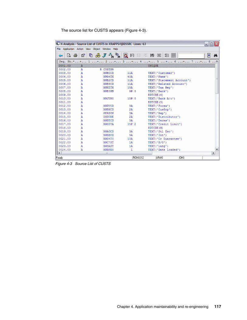
The source list for CUSTS appears (Figure 4-3).
Figure 4-3 Source List of CUSTS
Chapter 4. Application maintainability and re-engineering 117
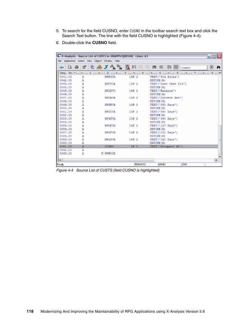
5. To search for the field CUSNO, enter CUSNO in the toolbar search text box and click the Search Text button. The line with the field CUSNO is highlighted (Figure 4-4).
6. Double-click the CUSNO field.
Figure 4-4 Source List of CUSTS (field CUSNO is highlighted)
118 Modernizing And Improving the Maintainability of RPG Applications using X-Analysis Version 5.6

The Variable Where Used window for CUSTS/CUSNO - Level 1 appears (Figure 4-5).
Figure 4-5 Variable Where Used for CUSTS/CUSNO - Level 1
7. To view Level 2, from the toolbar menu select View → VWU Level → Level 2. Variable Where Used for CUSTS/CUSNO - Level 2 appears (Figure 4-6).
Figure 4-6 Variable Where Used for CUSTS/CUSNO - Level 2
Chapter 4. Application maintainability and re-engineering 119

8. To view Level 3, from the toolbar menu select View → VWU Level → Level 3. Variable Where Used for CUSTS/CUSNO - Level 3 appears (Figure 4-7).
Figure 4-7 Variable Where Used for CUSTS/CUSNO - Level 3
9. To view Level 4, from the toolbar menu select View → VWU Level → Level 4. Variable Where Used for CUSTS/CUSNO - View Level 4 appears (Figure 4-8). View Level 4 displays the lines where CUSNO is passed as a parameter.
Figure 4-8 Variable Where Used for CUSTS/CUSNO - Level 4
10.To view Level 5, from the toolbar menu select View → VWU Level → Level 5. Variable Where Used for CUSTS/CUSNO - View Level 5 appears (Figure 4-9). View Level 5 displays the cascading parameters as well.
Figure 4-9 Variable Where Used for CUSTS/CUSNO - Level 5
120 Modernizing And Improving the Maintainability of RPG Applications using X-Analysis Version 5.6
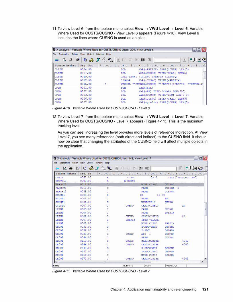
11.To view Level 6, from the toolbar menu select View → VWU Level → Level 6. Variable Where Used for CUSTS/CUSNO - View Level 6 appears (Figure 4-10). View Level 6 includes the lines where CUSNO is used as an alias.
Figure 4-10 Variable Where Used for CUSTS/CUSNO - Level 6
12.To view Level 7, from the toolbar menu select View → VWU Level → Level 7. Variable Where Used for CUSTS/CUSNO - Level 7 appears (Figure 4-11). This is the maximum tracking level.
As you can see, increasing the level provides more levels of reference indirection. At View Level 7, you see many references (both direct and indirect) to the CUSNO field. It should now be clear that changing the attributes of the CUSNO field will affect multiple objects in the application.
Figure 4-11 Variable Where Used for CUSTS/CUSNO - Level 7
Chapter 4. Application maintainability and re-engineering 121

13.We now examine the impact that such a change would have on one particular program, FAXSHT1. Make sure that the VWU level is set to 7 (Maximum tracking) and locate sequence number 11.0 for source member FAXSHT1.
14.Double-click the line with sequence number 11.0. X-Analysis opens FAXSHT1 at the line (Figure 4-12).
Figure 4-12 Source list highlighting the field reference
As CUSNO is moved to CUSNOA, any changes made to CUSNO will also apply to CUSNOA. By selecting the Member X-Ref for CUSNOA, you view all instances of CUSNOA and see how any changes to the end field will affect the application. Member X-Reference lists all source lines where CUSNOA has been referenced, in the member source and its associated device files and copybooks.
122 Modernizing And Improving the Maintainability of RPG Applications using X-Analysis Version 5.6
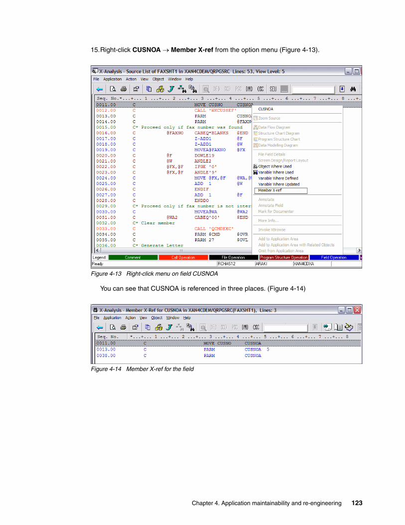
15.Right-click CUSNOA → Member X-ref from the option menu (Figure 4-13).
Figure 4-13 Right-click menu on field CUSNOA
You can see that CUSNOA is referenced in three places. (Figure 4-14)
Figure 4-14 Member X-ref for the field
Chapter 4. Application maintainability and re-engineering 123

16.Double-click the line for sequence number 13.00. Although line 13.00 remains highlighted, the source browser view is repositioned and the entire source file member is displayed (Figure 4-15). You can now scroll up and down the listing to view the context.
Figure 4-15 Source browser view with the selected line highlighted
As you can see, CUSNOA is a parameter passed to a program WKCUS8EF. The process can begin again by zooming into WKCUS8EF to track the impact on the parameters.
4.3 Application analysis and documentationA primary objective of X-Analysis is to facilitate understanding of existing applications. By enabling the user to rapidly build a conceptual view of the components to be maintained, performing the necessary code updates will be faster.
X-Analysis produces three different diagram types at the object level:
� Data Flow Diagrams (DFD)
� Structure Chart Diagrams (SCD)
� Data Model Diagrams (also referred to as Entity Relationship Diagrams). Data Model Diagrams are more fully described in “Exploring the application data model” on page 200.
Two diagrams are also at the application area level:
� Overview Structure Charts (OSC)� Application Area Data Model Diagrams
Each of these diagrams can be produced at both a detailed and an outline level. A detailed DFD also shows field usages between objects. A detailed SCD (OSC) also shows file usages.
124 Modernizing And Improving the Maintainability of RPG Applications using X-Analysis Version 5.6

4.3.1 Data Flow Diagrams (DFD)X-Analysis enables you to see how the objects within an application relate to each other. In the following example, we examine how the CUSTS object relates to the whole application. Follow these steps to complete the example:
1. Locate the CMS application in the Application Libraries list on the left pane of the X-Analysis client window. Expand the CMS application and double-click Source Files. A list of all source files in the library appears in the right pane of the window.
2. Double-click QDDSSRC in the right pane of the window. All of the source file members in source file CMS/QDDSSRC appear in the right pane.
3. In the Member List view, locate and select the member named CUSTS, and click the Data Flow Diagram button ( ) on the toolbar.
The Object Centered Data flow diagram view (Figure 4-16) opens. This dataflow diagram represents a graphical equivalent of the Object Where Used on CUSTS. From this diagram you see how CUSTS fits into the application (the programs used to update CUSTS), and the various logical views and access paths of CUSTS.
Figure 4-16 Object Centered Data Flow Diagram for CUSTS
The type of Objects in the Data Flow Diagram may be interpreted using the color-coded legend bar (Figure 4-17) at the bottom of the window.
Figure 4-17 Data Flow Diagram Legend Bar
4. To view field usage for any program, click the small gray button beside the program (Figure 4-18). This box may be located on either side of the program.
Figure 4-18 Field usage button on DFD item
Chapter 4. Application maintainability and re-engineering 125
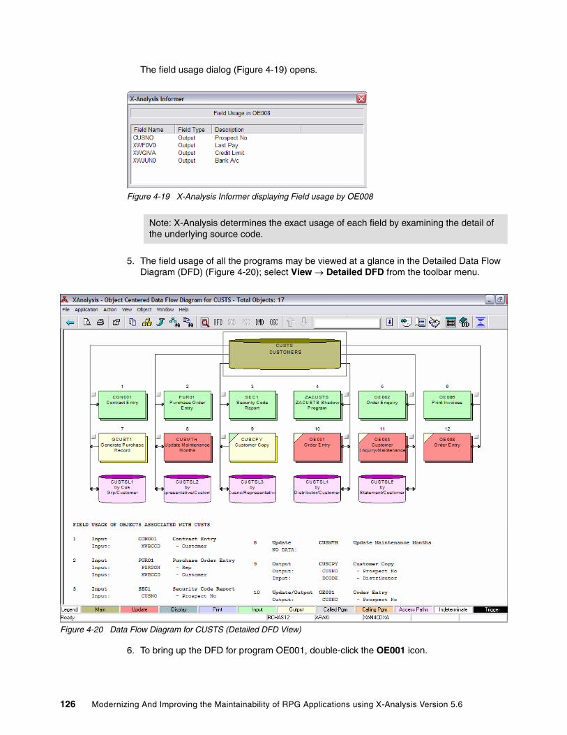
The field usage dialog (Figure 4-19) opens.
Figure 4-19 X-Analysis Informer displaying Field usage by OE008
5. The field usage of all the programs may be viewed at a glance in the Detailed Data Flow Diagram (DFD) (Figure 4-20); select View → Detailed DFD from the toolbar menu.
Figure 4-20 Data Flow Diagram for CUSTS (Detailed DFD View)
6. To bring up the DFD for program OE001, double-click the OE001 icon.
Note: X-Analysis determines the exact usage of each field by examining the detail of the underlying source code.
126 Modernizing And Improving the Maintainability of RPG Applications using X-Analysis Version 5.6

The DFD for OE001 appears (Figure 4-21). You can browse through a single large model. However, closer inspection reveals that in the case of a program that is not called by any other program, a double-click does not lead to another Data Flow Diagram.
Figure 4-21 Data Flow Diagram for OE001
4.3.2 Structure Chart Diagram (SCD)The structure chart is a nested tree diagram that shows the programs called and information about those programs.
To bring up the Structure Chart Diagram for OE001, right-click OEMEMU → Structure Chart Diagram. The Structure Chart Diagram for OEMENU appears (Figure 4-22).
Figure 4-22 OEMENU Structure Chart
OEMENU calls five programs. The nature of the called programs may be ascertained through the color-coded Structure Chart legend at the bottom of the screen (Figure 4-23).
Figure 4-23 Structure Chart Legend
Chapter 4. Application maintainability and re-engineering 127
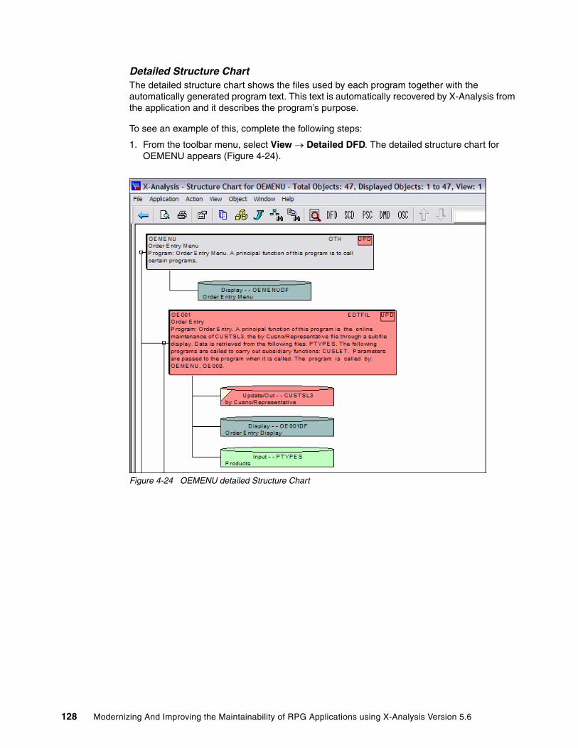
Detailed Structure ChartThe detailed structure chart shows the files used by each program together with the automatically generated program text. This text is automatically recovered by X-Analysis from the application and it describes the program’s purpose.
To see an example of this, complete the following steps:
1. From the toolbar menu, select View → Detailed DFD. The detailed structure chart for OEMENU appears (Figure 4-24).
Figure 4-24 OEMENU detailed Structure Chart
128 Modernizing And Improving the Maintainability of RPG Applications using X-Analysis Version 5.6

2. All of these charts can be printed. To see a print preview, click the Print Preview button. Figure 4-25 shows the print preview of OEMENU view ().
Figure 4-25 Print preview of OEMENU detailed Structure Chart
This can be printed if required. Close the print preview and return to the detailed structure chart.
Note: All diagrams are fully interactive. From any selected object, it is possible to select another diagram or zoom into the source code.
Chapter 4. Application maintainability and re-engineering 129
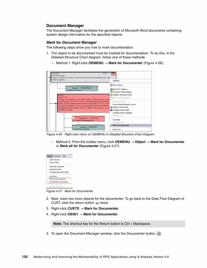
Document ManagerThe Document Manager facilitates the generation of Microsoft Word documents containing system design information for the specified objects.
Mark for Document ManagerThe following steps show you how to mark documentation:
1. The object to be documented must be marked for documentation. To do this, in the Detailed Structure Chart diagram, follow one of these methods:
– Method 1: Right-click OEMENU → Mark for Documenter (Figure 4-26).
Figure 4-26 Right-click menu on OEMENU in Detailed Structure Chart Diagram
– Method 2: From the toolbar menu, click OEMENU → Object → Mark for Documenter or Mark all for Documenter (Figure 4-27).
Figure 4-27 Mark for Documenter
2. Next, mark two more objects for the documenter. To go back to the Data Flow Diagram of CUST, click the return button twice.
3. Right-click CUSTS → Mark for Documenter.
4. Right-click OE001 → Mark for Documenter.
5. To open the Document Manager window, click the Documenter button .
Note: The shortcut key for the Return button is Ctrl + Backspace.
130 Modernizing And Improving the Maintainability of RPG Applications using X-Analysis Version 5.6

6. The Document Manager dialog box appears (Figure 4-28). Click Generate Document.
Figure 4-28 Document Manager
7. The Documentation Process dialog box (Figure 4-29) opens. You can choose to generate a single document with documentation for all objects marked for documentation or individual documents for each object marked for documentation. Click Generate Single System Document.
Figure 4-29 Documentation process dialog
8. The application document location dialog (Figure 4-30) opens. Enter a file name and click Save.
Figure 4-30 Application document location dialog
Chapter 4. Application maintainability and re-engineering 131

9. The System Documentation Wizard - Start window (Figure 4-31) opens. Click Next.
Figure 4-31 System Documentation Wizard - Start Window
10.The System Documentation Wizard - Specify Contents window (Figure 4-32) opens. Click Next.
Figure 4-32 System Documentation Wizard - Specify Contents window
132 Modernizing And Improving the Maintainability of RPG Applications using X-Analysis Version 5.6

11.The System Documentation Wizard - Specify Sequence window (Figure 4-33) opens. Confirm the sequence of the documentation and click Next.
Figure 4-33 System Documentation Wizard - Specify Sequence window
12.The System Documentation Wizard - Finish window (Figure 4-34) opens. To complete the operation, click Finish.
Figure 4-34 System Documentation Wizard - Finish window
The documenter runs, producing the required documentation. The documenter creates a table of contents and an index as well.
Chapter 4. Application maintainability and re-engineering 133

The document that has been produced can be viewed in Microsoft Word (Figure 4-35) from its saved location.
Figure 4-35 Print Preview of the System Document
4.4 Program analysis and understandingX-Analysis uses another set of constructs against the cross-reference repository to facilitate individual program understanding.
The program analysis facilities consist of:
� The source browser� Variable Where Used� Member X-Reference� Viewing source at different detail levels� Indented source� Pseudo code displays� Program flowchart� MS Visio � Business Rule displays
In the following section, each one of these facilities is described in detail.
4.4.1 The Source BrowserThe Source Browser displays the source code of an object and can be invoked in one of three ways:
� The right-click menu on any member or object on the Member/Object list. This presents Zoom Source as the first option, which opens the source of an object or member in the Source Browser.
Note: Flow charts are generated using Microsoft Visio and are shown as hyperlinks in the MS Word document.
Note: The System Documentation Wizard displays a warning message at the bottom:
WARNING: While System Documentation is in progress, using MS Word or Visio may hinder the documentation process. Please avoid such activity on the system while the document is being prepared.
134 Modernizing And Improving the Maintainability of RPG Applications using X-Analysis Version 5.6
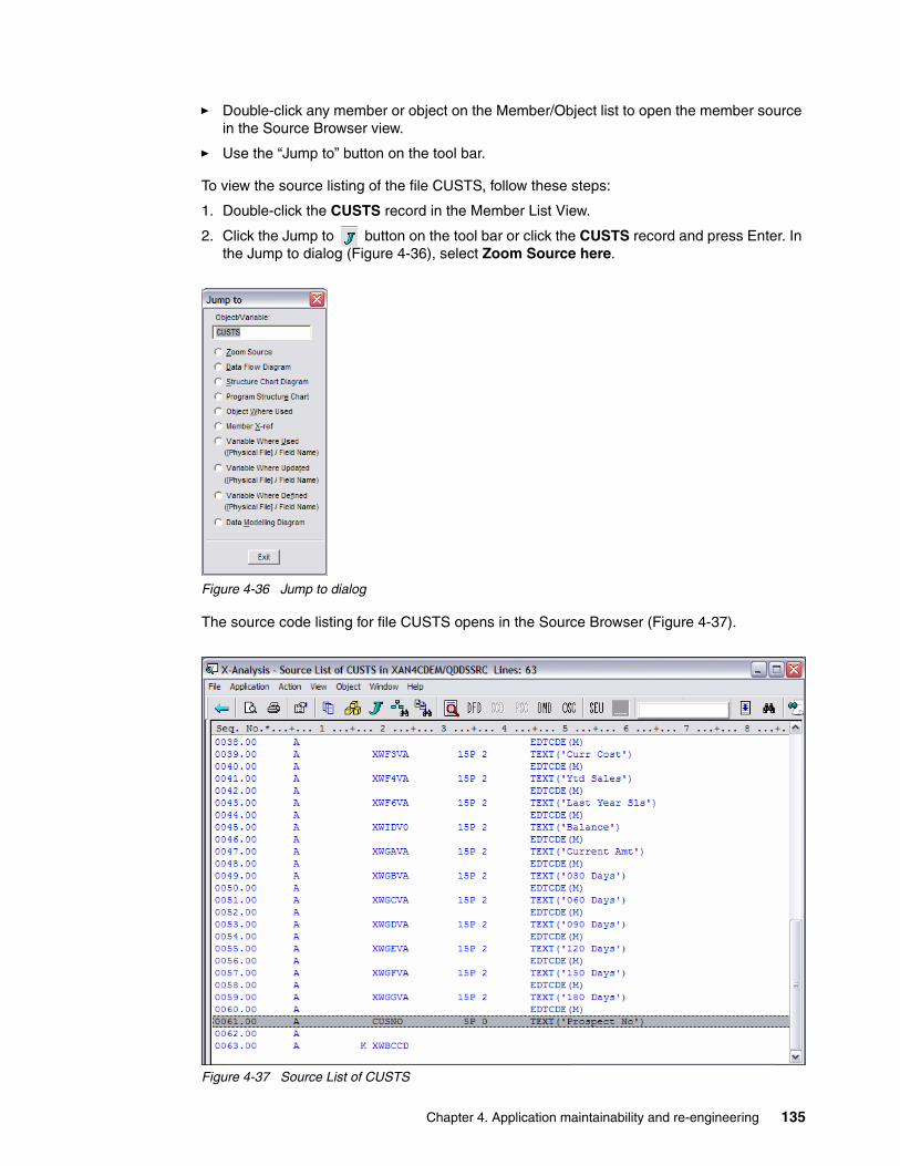
� Double-click any member or object on the Member/Object list to open the member source in the Source Browser view.
� Use the “Jump to” button on the tool bar.
To view the source listing of the file CUSTS, follow these steps:
1. Double-click the CUSTS record in the Member List View.
2. Click the Jump to button on the tool bar or click the CUSTS record and press Enter. In the Jump to dialog (Figure 4-36), select Zoom Source here.
Figure 4-36 Jump to dialog
The source code listing for file CUSTS opens in the Source Browser (Figure 4-37).
Figure 4-37 Source List of CUSTS
Chapter 4. Application maintainability and re-engineering 135

4.4.2 Variable Where UsedThe Variable Where Used (VWU) facility lists all of the source lines where the field or variable of a file or program has been referenced in the member source and its associated device files and copybooks, throughout the application. For further details about the VWU levels, refer to 4.2.1, “Variable Where Used” on page 114.
To display all references of CUSNO in CUSTS along with the associated line of code, complete the following steps:
1. Right-click the CUSNO in the Source List of CUSTS (Figure 4-38) and select Variable Where Used.
Figure 4-38 Source Lists of CUSTS
136 Modernizing And Improving the Maintainability of RPG Applications using X-Analysis Version 5.6

The Variable Where Used View opens (Figure 4-39). From this view you see all of the lines of all the source members that reference the CUSNO field.
Figure 4-39 Variable Where Used View for CUSTS/CUSNO
4.4.3 Member X-ReferenceMember X-Reference lists all of the source lines in which the selected field or variable has been used or referenced, in the member source (currently displayed) and its associated device files and copybooks. A wide variety of items can be specified including: files, array definitions, data structures, data structure sub-fields, indicators, key lists, data fields, file formats, subroutines, program variables, array elements, parameter lists, parameters, key fields, and EXCPT names.
Double-click a field in a member source to present the Member X-Reference view. Alternatively, you can choose Member X-ref using the right-click menu.
To perform a Member X-Reference on a variable, complete the following steps:
1. In the source list of source member OE001, the cursor is positioned on sequence number 38.00. Right-click the variable DSORDN and select Member X-ref (Figure 4-40).
Figure 4-40 Source list of OE001
Chapter 4. Application maintainability and re-engineering 137

Member X-Ref for DSORDN view (Figure 4-41) opens. Here you see all references to the field DSORDN in OE001 and its associated device files.
Figure 4-41 Member X-Ref for DSORDN
4.4.4 Viewing Source at different detail levelsThe Member X-Reference may be viewed at various levels using the source levels in the View menu. The View levels range from1 to 5 and are available only for program objects. The View menu on this display allows for indentation and five levels of source listing. Each level suppresses certain source lines such as:
� Level 5 shows all source lines.
� Level 4 suppresses all blank lines and comments.
� Level 3 removes source lines having opcodes such as MOVE and ADD and presents the remaining source lines.
� Level 2 suppresses the source lines having opcodes such as IF/ELSE/END and DOW/DOU and leaves file information, comments, and so forth.
� Level 1 presents only the comments and the CALL/EXSR statements.
Source lines have the following color codes:
� Call operations such as CALL or ESXR are in red.
� Conditional constructs such as IF/ELSE/END, DO/WHILE, and DO/UNTIL are in dark brown.
� Field operations such as MOVE and ADD are in blue.
� Program structure statements are in dark magenta.
� Comments are in green.
� The rest of the source lines are in black.
In the following example, the source view level of program OE001 is changed to level 1. This reduces the number of source lines that are displayed. The source view level is then incrementally changed back up to level 5. Follow these steps to complete the example:
1. At the Member X-Ref for DSORDN screen, click the Return button on the tool bar to return to the OE001 Source Listing.
138 Modernizing And Improving the Maintainability of RPG Applications using X-Analysis Version 5.6

2. On the toolbar menu (Figure 4-42), select View → Source Level → Level 1.
Figure 4-42 Source levels on Source browser
3. The source list for OE001 is reduced to the absolute minimum. Only the subroutines and comments are displayed (Figure 4-43).
Figure 4-43 OE001 Source list - View level 1
4. Incrementally increase the source level from 1 to 5 to see the number of source lines increase. Selecting View → Source Level → Level 5 returns you to normal source listing.
Chapter 4. Application maintainability and re-engineering 139

4.4.5 Indented SourceThe indented source view presents the source listing in an indented format. Source lines within all conditional or flow of control statements such as IF/ELSE/END and DO/WHILE are shown indented. The indented source view improves code readability and helps you comprehend the program logic. This view is especially helpful when viewing Original Program Model (OPM) RPG program source file listings due to the columnar format restrictions of these programs.
To display the indented source view, complete the following steps:
1. In the source listing for OE001 make sure you are at View Level 5. From the toolbar menu, select View → Indented Source. The Indented Source view for OE001 opens (Figure 4-44).
Figure 4-44 OE001 Indented source view
2. Select View → Source Code to return to normal source listing.
140 Modernizing And Improving the Maintainability of RPG Applications using X-Analysis Version 5.6

4.4.6 Pseudo Code DisplaysIn the Pseudo Code view, the source lines are displayed as English statements. Java and other non-RPG programmers may find this view the most helpful to read and aid in understanding the program logic.
To display Pseudo Code view for OE001, complete the following steps:
1. In the source listing for OE001 make sure you are at View Level 5. From the toolbar menu, select View → Pseudo Code. The Pseudo Code view for OE001 opens (Figure 4-45).
Figure 4-45 OE001 Pseudo Code view
2. Select View → Source Code to return to normal source listing.
Chapter 4. Application maintainability and re-engineering 141

4.4.7 Program flowchartsProgram Structure Chart (PSC) graphically displays the sequence of calls in a program. The call could be to execute subroutines, programs, modules, or procedures in service programs. The item circled in Figure 4-46 represents a subroutine. Subroutines are depicted by small gray rectangles containing the name of the subroutine.
To display the Program Structure Chart for program OE001, complete the following steps.
1. In the source listing for OE001, click the Program Structure Chart button .
2. From the toolbar menu, select Object → Program Structure Chart.
Figure 4-46 Program Structure Chart
All other items (modules, procedures, and service programs), are the same size as the program element for OE001. The function type determines the background color for these items (refer to Figure 4-23 on page 127 for the color-coded Structure Chart legend).
3. Double-click the $RVCUS subroutine in the Program Structure Chart. The Source List of OE001 with the line EXSR $RVCUS highlighted is displayed (Figure 4-47).
Figure 4-47 Zoom to $RVCUS subroutine from OE001 Program Structure Chart
142 Modernizing And Improving the Maintainability of RPG Applications using X-Analysis Version 5.6

4.4.8 Microsoft Visio flow chartsX-Analysis has the ability to generate a flow chart of the program using Microsoft Visio. This option is available only in the Source Browser view and can be performed only for OPM RPG and ILE RPG programs.
To generate a Visio flow chart for program OE001, complete the following steps:
1. In the source listing for OE001, select View → Flowchart in MS Visio. Microsoft Visio opens showing a flow chart of OE001 (Figure 4-48).
Figure 4-48 Flowchart of OE001 generated using Visio
4.4.9 Business rulesThe Business Rules view enables you to see the business rule logic highlighted within the member. You can immediately see the business logic within the context of the program as a whole.
Business rules are generated automatically by the reverse-engineering operations described in 3.8, “Running the X-Analysis MVC re-engineering process” on page 60. During this process, the program source is grouped into discreet blocks of logic so that each block represents a particular execution of a business rule. Blocks of code are then converted to pseudo code that describes the execution of the logic. Literals and constants, used where possible in the narration, produce very accurate descriptions of the logic. Each rule has a unique identifier that makes systemwide analysis and documentation of business rules possible in X-Analysis.
Chapter 4. Application maintainability and re-engineering 143

The Business Rules view is enabled only for the OPM RPG and ILE RPG programs. It can be selected from all source views (Normal, Indented, Pseudo Code).
The program OE001 is not a good example for this exercise because it does not contain any business rules. To showcase the features of this Business Rules view, we use the program CUSFMAINT instead.
To view the business logic for CUSFMAINT, complete the following steps:
1. On left side of the X-Analysis development environment, double-click Programs under the Application tree for CMS.
2. At the Work with Objects window (Figure 4-49), click OK.
Figure 4-49 Work with Objects window
Note: Business Rules Code and Business Rules Pseudo Code highlight the major file operations in the program, along with related comments.
144 Modernizing And Improving the Maintainability of RPG Applications using X-Analysis Version 5.6
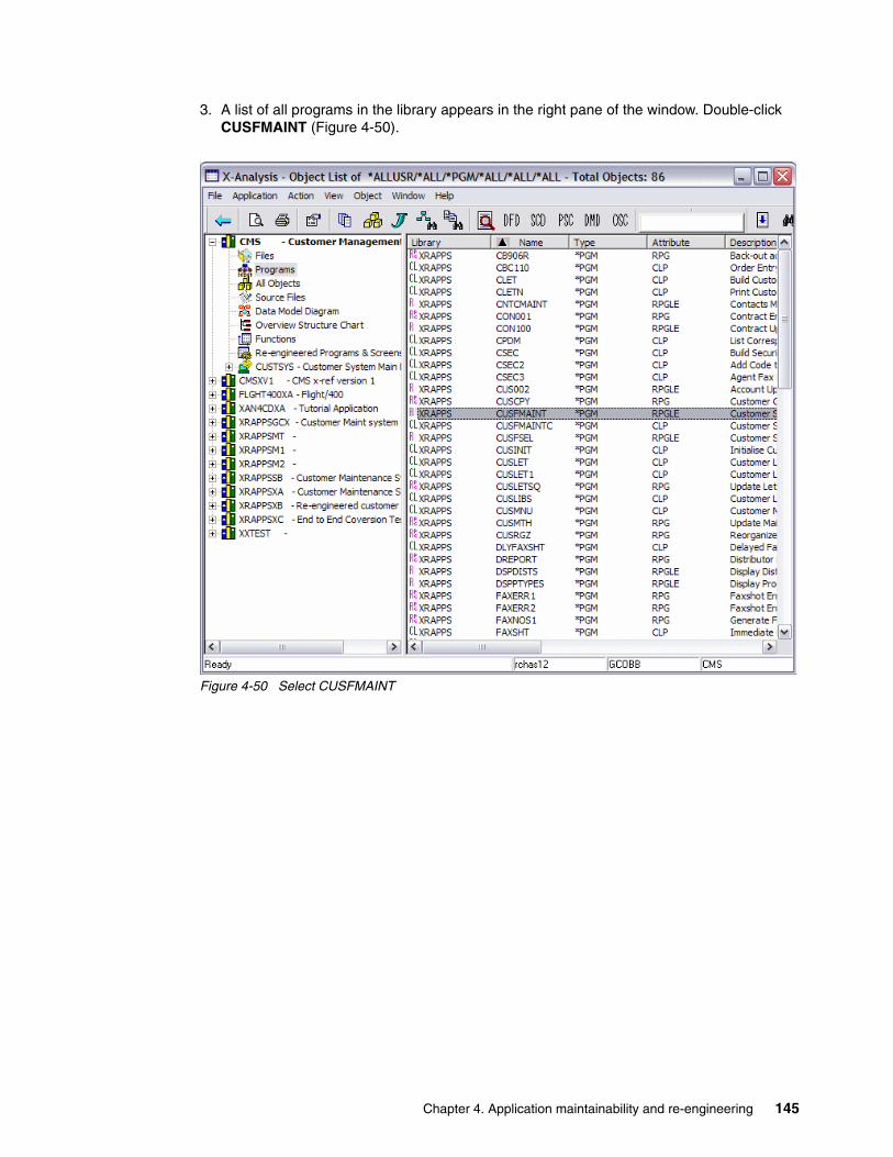
3. A list of all programs in the library appears in the right pane of the window. Double-click CUSFMAINT (Figure 4-50).
Figure 4-50 Select CUSFMAINT
Chapter 4. Application maintainability and re-engineering 145
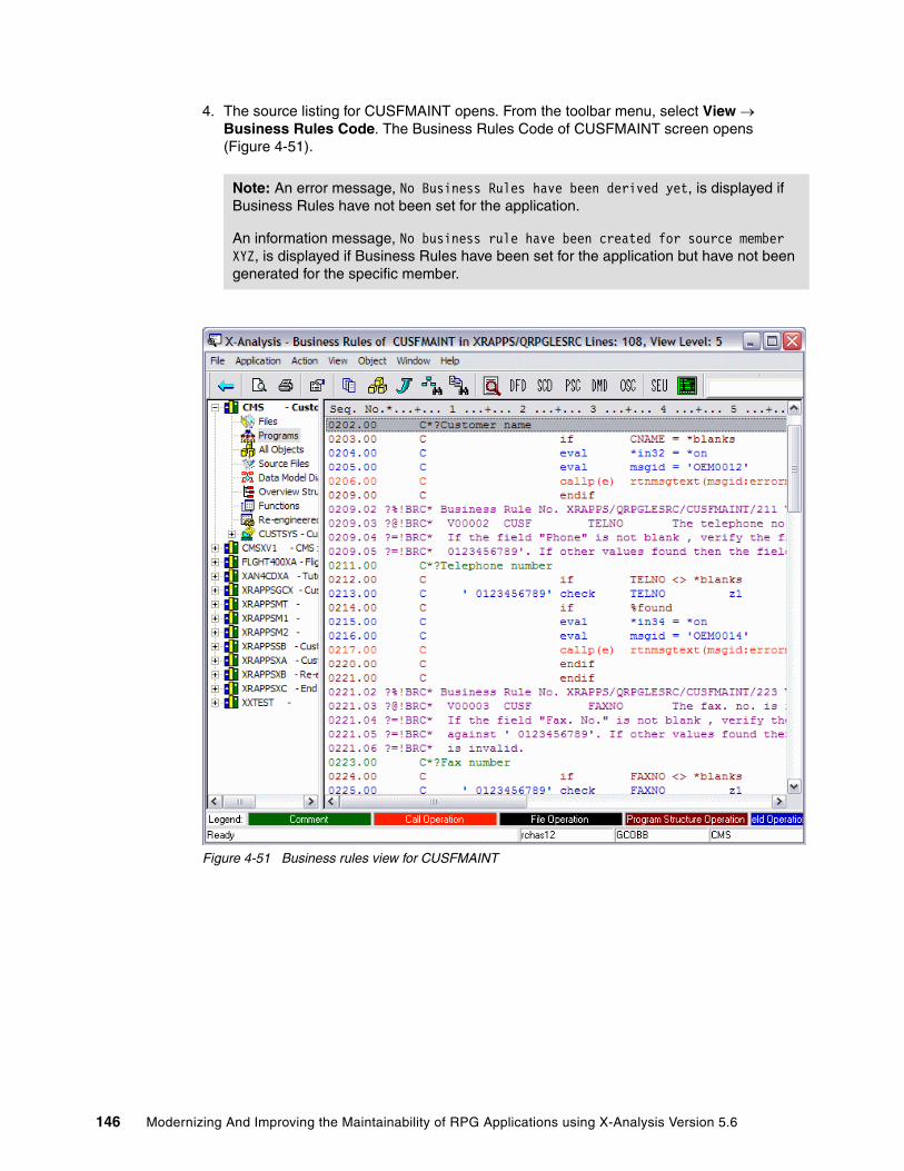
4. The source listing for CUSFMAINT opens. From the toolbar menu, select View → Business Rules Code. The Business Rules Code of CUSFMAINT screen opens (Figure 4-51).
Figure 4-51 Business rules view for CUSFMAINT
Note: An error message, No Business Rules have been derived yet, is displayed if Business Rules have not been set for the application.
An information message, No business rule have been created for source member XYZ, is displayed if Business Rules have been set for the application but have not been generated for the specific member.
146 Modernizing And Improving the Maintainability of RPG Applications using X-Analysis Version 5.6

5. To look at the business rules Pseudo Code view of this program, from the toolbar menu select View → Business Rules Pseudo Code. The Business Rules Pseudo Code display for CUSFMAINT opens (Figure 4-52).
Figure 4-52 Business rules Pseudo Code view for CUSFMAINT
4.5 Using X-Analysis cross-reference repository for modernizing
This section provides a detailed description of the X-Analysis cross-reference repository and shows how it can be used to aid in application modernization activities. The objective is to provide information so you can use the data in the repository for your own specific modernization requirements. When you understand the format, architecture, and content of the database, you can determine whether developing custom programs to automate application modernization changes is appropriate.
4.5.1 X-Analysis cross-reference repository detailsAs described earlier, X-Analysis builds a cross-reference repository of every line of source code in the existing application. This repository is then completely cross-indexed and analyzed, enabling any cross-reference query to run instantly. Much of the information stored in the cross-reference repository can be used in modernization activities (for example, making
Chapter 4. Application maintainability and re-engineering 147

existing RPG applications more maintainable or converting existing applications into reusable components). The following list provides some specific modernization activities that the X-Analysis cross-reference repository could be used for:
� Using prototypes for program calls� Converting subroutines to procedures� Using reusable database I/O routines� Removing indicator usage� Removing usage of program defined files� Placing definitions in D-Specs at the start of programs� Eliminating GOTO and CAB operations
In this section, we focus on two of the tables in the X-Analysis cross-reference repository, X@XPGRF and XAGWU. (The subsequent section gives details about format and usage of these tables.) A sample utility program that demonstrates how you can use the data in the cross-reference repository to perform a specific application modernization task is provided. The X-Analysis cross-reference repository is comprised of many tables, which are documented in detail in Appendix B, “X-Analysis cross-reference repository details” on page 257.
Table X@XPGRF program object referencesX@XPGRF contains objects referenced by programs, commands, and menus. These references are retrieved primarily from object data. However, the source is also interpreted for additional references. There are two equivalent files:
� XVXPGREF for variant libraries� XPROCREF for OCL
X@XPGRF and its equivalents are used to:
� Provide comprehensive Object Where Used data.� Enable complete investigation of program references.
Table 4-1 X@XPGRF file layout
Field Datatype Length Description
WHPNAM CHAR 10 The name of the program, CMD or MENU
WHTEXT CHAR 50 The text held against WHPNAM
WHFNAM CHAR 11 The name of the referenced object
WHOBTP CHAR 1 The type of referenced object:P - ProgramF - FileD - Data areaC - Command
WUSAGE CHAR 1 The object type usage:I - Input fileU - Update or input fileO - Output fileA - Input and output fileB - Input, output, and update fileC - Command calls command processing programV - Command calls validity checking programI - Program calls program or calls commandT - Trigger program input fileS - Trigger program update file
148 Modernizing And Improving the Maintainability of RPG Applications using X-Analysis Version 5.6

Table XAGWU X-Analysis Where Used dataXAGWU (X-Analysis Where Used data) is an index of each significant word in each source member with an allowable source type. The source member details are stored (library, file, member, type, relative record number (RRN)) together with the variable name, type, and whether modified. When used with alias and rename data this allows instant cross-reference of any variable, constant, or such against the entire application.
To retrieve an occurrence of a variable, use the source member details to open the source file member, then use the RRN to retrieve the individual source record. Use a standard procedure to interpret the source line. The source file attribute (VATTR) determines which standard procedure is used to interpret the source. For COBOL, the field sequence no. (VVARSQ) allows determination of the specific occurrence of the field in the statement. Where statements extend over several source lines, standard procedures are used to build the complete statements, reading both backward and forward through the source member.
Table 4-2 XAGWU file layout
Note: The object type of the WHPNAM field may be implied by the value of the WUSAGE. This is important when an object such as a program and a command have the same name. When WUSAGE = C or V, the WHPNAM object type is command, otherwise the WHPNAM object type is a program.
Field Datatype Length Description
VSRCLB CHAR 10 Source library
VSRCFL CHAR 10 Source file
VSRCMB CHAR 10 Source member
VOBTY CHAR 2 Variable type:AA - Start of program logic sectionCL - Called programCN - Constant/literalEF - Externally defined data structureIN - IndicatorPI - Procedure interface definitionSR - Start of ILE RPG subroutine, COBOL section, or paragraph
VRECN PACKED 5,0 RRN where the variable occurs in the source member
VMOD CHAR 1 Indicates, if relevant, whether the variable is modified
VATTR CHAR 2 Indicates the source member attribute:CL - CL variant (CLP, CL, CLLE)RG - RPG variant (RPG, RPG38, SQLRPG)RI - RPGLE variant (RPGLE, SQLRPGLE)CB - COBOL variant (CBL)PF - PF variantLF - LF variantDS - DSPF variantPR - PRTF variantOC - OCLSQ - SQLUS - User spaceAL - Alias-only record (enables retrieval of references to a variable when it occurs only as an alias in a source member)
Chapter 4. Application maintainability and re-engineering 149

4.5.2 Using the repository: an example programThe sample utility program XREFEXAMPL, demonstrates how you can use the information provided in the X-Analysis cross-reference repository. This is an SQLRPGLE program that uses Structured Query Language (SQL) access methods to search the repository files for program references to a specified program (passed in as an input parameter). The utility program performs the following actions:
� If the specified program is referenced by the use of a dynamic, unbound call (operation code CALL), the utility replaces it with a prototyped call (operation code CALLP).
� It converts the CALL parameter list format to the CALLP parameter format, generates the prototype in a separate member, and inserts a copybook statement to that prototype member.
� All changes described are applied to a new source file member (leaving the original source file member intact and unchanged). The new source file member has the same name as the original, but the first character is replaced with Z. (If the name of the original member is OE001, the new member containing the changes would be named ZE001.)
You may be wondering why we chose to highlight this particular modification in the example program and what it has to do with application modernization. Prototyped calls have several advantages over non-prototyped calls:
� The compiler can check whether the correct types and lengths of parameters are used.
� When prototyped, a program call can be easily changed to a procedure call by simply changing the prototype from EXTPGM to EXTPROC.
� The CONST keyword can be used on a parameter definition of a prototyped call to indicate that a constant value is being passed.
The following sample utility program is coded to handle certain cases and coding styles. If you decide to use it, examine it carefully and make changes to tailor it to your environment. The program in its current form makes the following assumptions:
� The programs being searched in the cross-reference repository are ILE RPG programs.
� The source file containing members to examine and change is named QRPGLESRC.
� The parameter lists of all dynamic calls are specified on the lines following the CALL operation code, using the PARM operation. No dynamic calls are using the name PLIST. In addition, the parameter variables are defined on the same line as the PARM operation code.
� Member names do not start with the letter Z because new members are generated and named by copying the name of the original member and replacing the first character with the letter Z.
For instructions about how to download this sample program, refer to “Restoring the xrefexampl.savf library” on page 268.
VVARSQ PACKED 5,0 The sequence number (position) of the variable within the source statement (or the part of it that is on the source line if the statement extends over more than one line). This only applies to COBOL and free-format ILE RPG.
Field Datatype Length Description
150 Modernizing And Improving the Maintainability of RPG Applications using X-Analysis Version 5.6

Example 4-1 Example program to convert dynamic calls to prototyped calls
hDftActGrp(*NO) hoption(*srcstmt : *nodebugio)// Program: XREF_EXP // X-Analysis X-Ref Database Example Program. // This sample utility pgm provides an example of how one can use // the information stored in the X-Analysis X-Ref Database. // In this example utility pgm, a program name and source file // library are accepted as input parameters. The X-Ref database // is then searched to find all other programs that make dynamic, // non-bound calls to the specified program. If any are found, this // utility creates a copy of the program’s source member and replaces // all instances of dynamic calls (operation code 'CALL') with // prototyped calls (operation code 'CALLP'). The parameter list of // the dynamic call is also converted to callp parameter // format. Finally, a prototype is generated in a seperate // member and a copybook with that prototype is inserted. // To create this program: // CRTSQLRPGI OBJ(OBJLIB/XREFEXAMPL) // SRCFILE(SRCLIB/QRPGLESRC) COMMIT(*NONE) // To run: // 1- Add both cross-reference library and source file library // to your library list // 2- CALL PGM(XREFEXAMPL/XREFEXAMPL) PARM(yourPgmName yourSrcFilLib)
// --------------------------------------------------------------- // Global variables, data structures, constants // --------------------------------------------------------------- d pgmRefRow e ds extname(x@xpgrf) d gwuRow e ds extname(xagwu) d rpgleRow e ds extname(qrpglesrc) d protoRow e ds extname(qrpglesrc) prefix(pr_) d insertRow e ds extname(qrpglesrc) prefix(i_) d srcMbrRow ds d srcStm like(srcdta) d srcRRN 15p 0 // Input parameters d inPgmNam s 10a d inSrcLibNam s 10a // Constants d upper c 'ABCDEFGHIJKLMNOPQRSTUVWXYZ' d lower c 'abcdefghijklmnopqrstuvwxyz'
d procCall s 35a d parmNam s 10a d parmCount s 3s 0 d parmArray s 10a dim(100) d parmLenArr s 5a dim(100) d parmDecLenArr s 2a dim(100) d pc s 3s 0 d newMbrNam s 10a d srcStmUC s like(srcdta) d newLine s like(srcdta) d nxtRRN s like(vrecn) d specCode s 1a d ovrdbfFlag s 1a d insCBkFlag s 1a d genProFlag s 1a d qcmd s 120a // ---------------------------------------------------------------
Chapter 4. Application maintainability and re-engineering 151
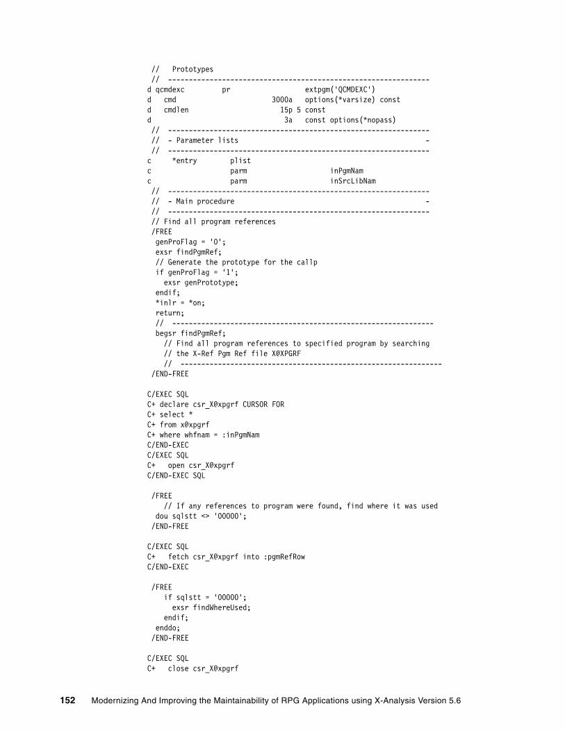
// Prototypes // --------------------------------------------------------------- d qcmdexc pr extpgm('QCMDEXC') d cmd 3000a options(*varsize) const d cmdlen 15p 5 const d 3a const options(*nopass) // --------------------------------------------------------------- // - Parameter lists - // --------------------------------------------------------------- c *entry plist c parm inPgmNam c parm inSrcLibNam // --------------------------------------------------------------- // - Main procedure - // --------------------------------------------------------------- // Find all program references /FREE genProFlag = '0'; exsr findPgmRef; // Generate the prototype for the callp if genProFlag = '1'; exsr genPrototype; endif; *inlr = *on; return; // --------------------------------------------------------------- begsr findPgmRef; // Find all program references to specified program by searching // the X-Ref Pgm Ref file X@XPGRF // --------------------------------------------------------------- /END-FREE
C/EXEC SQL C+ declare csr_X@xpgrf CURSOR FOR C+ select * C+ from x@xpgrf C+ where whfnam = :inPgmNam C/END-EXEC C/EXEC SQL C+ open csr_X@xpgrf C/END-EXEC SQL
/FREE // If any references to program were found, find where it was used dou sqlstt <> '00000'; /END-FREE
C/EXEC SQL C+ fetch csr_X@xpgrf into :pgmRefRow C/END-EXEC
/FREE if sqlstt = '00000'; exsr findWhereUsed; endif; enddo; /END-FREE
C/EXEC SQL C+ close csr_X@xpgrf
152 Modernizing And Improving the Maintainability of RPG Applications using X-Analysis Version 5.6

C/END-EXEC SQL
/FREE endsr; //--------------------------------------------------------------- begsr findWhereUsed; // Find where the reference pgm is used. //--------------------------------------------------------------- ovrdbfFlag = '0'; /END-FREE
C/EXEC SQL C+ declare csr_xagwu CURSOR FOR C+ select * C+ from xagwu C+ where vsrcfl = 'QRPGLESRC' c+ and vsrcmb = :whpnam c+ and vname = :whfnam C/END-EXEC C/EXEC SQL C+ open csr_xagwu C/END-EXEC SQL
/FREE dou sqlstt <> '00000'; /END-FREE
C/EXEC SQL C+ fetch csr_xagwu into :gwuRow C/END-EXEC
/FREE if sqlstt = '00000';
// VSRCMB contains name of the source member. Override to this source // member with this name. if ovrdbfFlag = '0'; qcmd = 'OVRDBF FILE(QRPGLESRC) ' + 'TOFILE(' + %trim(inSrcLibNam) + '/QRPGLESRC) '+ 'MBR(' + %trim(VSRCMB) +')'; CallP(e) Qcmdexc(qcmd : %Len(%Trim(qcmd))); exsr crtNewMbr; ovrdbfFlag = '1'; endif;
// Find program parameters, update the source member procCall = %trim(vname) + '('; exsr findParms; exsr updSrcMbr;
endif; enddo; /END-FREE
C/EXEC SQL C+ close csr_xagwu C/END-EXEC SQL
Chapter 4. Application maintainability and re-engineering 153

/FREE // Insert the prototype copybook. // Last, delete override to src file members if ovrdbfFlag = '1'; exsr insProCpyBk; qcmd = 'DLTOVR FILE(QRPGLESRC) '; CallP(e) Qcmdexc(qcmd : %Len(%Trim(qcmd))); qcmd = 'DLTOVR FILE(QRPGLENEW) '; CallP(e) Qcmdexc(qcmd : %Len(%Trim(qcmd))); endif; endsr;
// --------------------------------------------------------------- begsr findParms; // Find source statements that contains the parameters // that follow the program call // ---------------------------------------------------------------
// VRECN contains relative record number of the source statement // that contains the Call to the program. By selecting all // records greater than this RRN, we can find all parms // that follow the program call. /END-FREE C/EXEC SQL C+ declare csr_qrpglesrc CURSOR FOR C+ select srcdta, rrn(qrpglenew) C+ from qrpglenew C+ where rrn(qrpglenew) > :VRECN c+ order by rrn(qrpglenew) C/END-EXEC C/EXEC SQL C+ open csr_qrpglesrc C/END-EXEC SQL /FREE parmCount = 0; dou sqlstt <> '00000'; /END-FREE C/EXEC SQL C+ fetch csr_qrpglesrc into :srcMbrRow C/END-EXEC
/FREE // See if the rpg statement following the call contains a // parameter operation. This assumes that the PARM operations // immediately follow the CALL operation (not using the PLIST // operation) if sqlstt <> '00000'; leave; endif;
// Skip comment lines if %subst(srcstm:7:1) = '*'; iter; endif;
// Convert the source statment to upper case. Then compare // the contents of the source statement at positions 26-29 with 'PARM' // If no match, leave the loop, we are done. srcStmUC = %xlate(lower : upper : srcStm); if %subst(srcStmUC:26:4)<>'PARM';
154 Modernizing And Improving the Maintainability of RPG Applications using X-Analysis Version 5.6

leave; endif;
// If we are here, we have found a PARM statement. Extract parm and // construct parameter list in prototyped call format. parmCount = parmCount + 1; parmNam = %subst(srcStmUC:50:10); parmArray(parmCount) = parmNam; parmLenArr(parmCount) = %subst(srcStmUC:64:5); parmDecLenArr(parmCount) = %subst(srcStmUC:69:2); if parmCount = 1; procCall = %trim(procCall) + %trim(parmNam); else; procCall = %trim(procCall) + ' : ' + %trim(parmNam); endif; enddo; procCall = %trim(procCall) + ')';
/END-FREE C/EXEC SQL C+ close csr_qrpglesrc C/END-EXEC SQL /FREE endsr;
// --------------------------------------------------------------- begsr updSrcMbr; // Update the line that contains the program call. Replace program // call with prototyped call. // --------------------------------------------------------------- newLine = *blanks; %subst(newline:6:1) = 'c'; %subst(newline:26:5) = 'callp'; %subst(newline:36:35)= procCall; /END-FREE
C/EXEC SQL C+ update qrpglenew C+ set srcdta = :newLine C+ where rrn(qrpglenew) = :VRECN C/END-EXEC
/FREE // Delete the lines following the pgm call that contain the // PARM operation for pc = 1 to parmCount; %subst(newline:6:2) = ' *'; nxtRRN = vrecn + pc; /END-FREE C/EXEC SQL C+ delete from qrpglenew C+ where rrn(qrpglenew) = :nxtRRN C/END-EXEC /FREE endfor;
genProFlag = '1'; endsr;
Chapter 4. Application maintainability and re-engineering 155
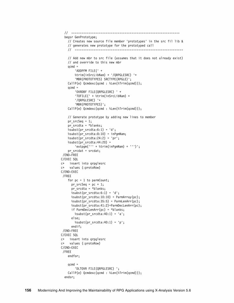
// --------------------------------------------------------------- begsr GenPrototype; // Creates new source file member 'prototypes' in the src fil lib & // generates new prototype for the prototyped call // ---------------------------------------------------------------
// Add new mbr to src file (assumes that it does not already exist) // and override to this new mbr qcmd = 'ADDPFM FILE(' + %trim(inSrcLibNam) + '/QRPGLESRC) '+ 'MBR(PROTOTYPES) SRCTYPE(RPGLE)'; CallP(e) Qcmdexc(qcmd : %Len(%Trim(qcmd))); qcmd = 'OVRDBF FILE(QRPGLESRC) ' + 'TOFILE(' + %trim(inSrcLibNam) + '/QRPGLESRC) '+ 'MBR(PROTOTYPES)'; CallP(e) Qcmdexc(qcmd : %Len(%Trim(qcmd)));
// Generate prototype by adding new lines to member pr_srcSeq = 1; pr_srcdta = *blanks; %subst(pr_srcdta:6:1) = 'd'; %subst(pr_srcdta:8:10) = inPgmNam; %subst(pr_srcdta:24:2) = 'pr'; %subst(pr_srcdta:44:20) = 'extpgm(''' + %trim(inPgmNam) + ''')'; pr_srcdat = srcdat; /END-FREE C/EXEC SQL c+ insert into qrpglesrc c+ values (:protoRow) C/END-EXEC /FREE for pc = 1 to parmCount; pr_srcSeq = pc + 1; pr_srcdta = *blanks; %subst(pr_srcdta:6:1) = 'd'; %subst(pr_srcdta:10:10) = ParmArray(pc); %subst(pr_srcdta:35:5) = ParmLenArr(pc); %subst(pr_srcdta:41:2)=ParmDecLenArr(pc); if ParmDecLenArr(pc) = *blanks; %subst(pr_srcdta:40:1) = 'a'; else; %subst(pr_srcdta:40:1) = 'p'; endif; /END-FREE C/EXEC SQL c+ insert into qrpglesrc c+ values (:protoRow) C/END-EXEC /FREE endfor;
qcmd = 'DLTOVR FILE(QRPGLESRC) '; CallP(e) Qcmdexc(qcmd : %Len(%Trim(qcmd))); endsr;
156 Modernizing And Improving the Maintainability of RPG Applications using X-Analysis Version 5.6

// --------------------------------------------------------------- begsr InsProCpyBk; // Insert prototype copybook statement in D-specs // The lines of source file members appear in arrival sequence. // This means, unfortunately, that new lines cannot just be // inserted in source file members. // The records of the member must be read and written to a // temp space. When you arrive at the point in which you want to // insert the new line, write that new line to the temp space. // Once you've written the whole member to the temp space (including the // newly inserted lines), delete all records from the original mbr, and // copy all rows from the temp back back into original src mbr // ---------------------------------------------------------------
insCbkFlag = '0';
// Create and clear a temp table to store temp results /END-FREE C/EXEC SQL c+ create table qtemp/qrpgletmp as c+ (select * from qrpglesrc) with no data C/END-EXEC C/EXEC SQL c+ delete from qtemp/qrpgletmp C/END-EXEC
// Open cursor for original source member (we still // have an override on it at this point) C/EXEC SQL C+ declare csr_qrpglesrc2 CURSOR FOR C+ select * C+ from qrpglenew c+ order by rrn(qrpglenew) C/END-EXEC C/EXEC SQL C+ open csr_qrpglesrc2 C/END-EXEC SQL
/FREE // Fetch the rows from the orignal source member dou sqlstt <> '00000'; /END-FREE
C/EXEC SQL C+ fetch csr_qrpglesrc2 into :rpgleRow C/END-EXEC
/FREE if sqlstt <> '00000'; leave; endif;
// Find first D-spec and insert the prototype statement // immediately before that statement specCode = %subst(srcDta:6:1); if (specCode = 'd' or specCode = 'D') and insCbkFlag = '0'; i_srcSeq = srcSeq - .01; i_srcdta = *blanks;
Chapter 4. Application maintainability and re-engineering 157

%subst(i_srcdta:7:20) = '/copy prototypes'; i_srcdat = srcdat; insCbkFlag = '1'; /END-FREE C/EXEC SQL c+ insert into qrpgletmp c+ values (:insertRow) C/END-EXEC /FREE endif;
// Write the original source member record to the temp table /END-FREE C/EXEC SQL c+ insert into qrpgletmp c+ values (:rpgleRow) C/END-EXEC
/FREE enddo;
// Now clear the records from the original source member // and copy all records from temp table into it /END-FREE C/EXEC SQL c+ delete from qrpglenew C/END-EXEC C/EXEC SQL c+ insert into qrpglenew c+ select * from qrpgletmp c+ order by rrn(qrpgletmp) C/END-EXEC C/EXEC SQL C+ close csr_qrpglesrc2 C/END-EXEC SQL
/FREE endsr;
// --------------------------------------------------------------- begsr crtNewMbr; // Create new source member to store results of conversion // ---------------------------------------------------------------
// Create new member. Use old member name and change name to start with Z newMbrNam = vSrcMb; %subst(newMbrNam:1:1) = 'Z'; qcmd = 'ADDPFM FILE(' + %trim(inSrcLibNam) + '/QRPGLESRC) '+ 'MBR(' + %trim(newMbrNam) +') SRCTYPE(RPGLE)'; CallP(e) Qcmdexc(qcmd : %Len(%Trim(qcmd))); qcmd = 'OVRDBF FILE(QRPGLENEW) ' + 'TOFILE(' + %trim(inSrcLibNam) + '/QRPGLESRC) '+ 'MBR(' + %trim(newMbrNam) +')'; CallP(e) Qcmdexc(qcmd : %Len(%Trim(qcmd)));
// Clear a temp table to store temp results
158 Modernizing And Improving the Maintainability of RPG Applications using X-Analysis Version 5.6

/END-FREE C/EXEC SQL c+ delete from qrpglenew C/END-EXEC C/EXEC SQL c+ insert into qrpglenew c+ select * from qrpglesrc c+ order by rrn(qrpglesrc) C/END-EXEC /FREE endsr;
4.6 Performing field re-engineeringThis section introduces you to the field re-engineering capabilities of X-Analysis. By definition, field re-engineering means changing the attributes of an existing database field. The primary example of field re-engineering is field expansion. The effects of a field re-engineering change may be far-reaching and have a profound impact on the application. The database file itself must be changed, as well as all of the dependent logical files, display files, programs, modules, and service programs that reference that field. In addition, renamed fields, program parameters, and work variables also must be considered; thus the importance of the tool to identify object dependencies, perform the necessary impact analysis, carry out the actual source member conversion (for all of the impacted files and programs), and execute all of the necessary recompiling.
The field re-engineering process is performed by X-Resize, an X-Analysis extension. X-Resize utilizes X-Analysis impact analysis capabilities to identify all objects that are affected by the field change. It performs the necessary conversions by updating the source file members (if deemed necessary) of all identified objects and recompiling those objects.
The underlying function of X-Analysis that performs the impact analysis is called Variable Where Used (VWU). VWU lists all of the source lines where the field or variable of a file or program has been used or referenced in the Member source and its associated device files and copybooks, throughout the application. For more information about VWU and the view levels, refer to 4.2.1, “Variable Where Used” on page 114.
The example field re-engineering process scenario identifies a field expansion effort. This scenario requires expanding the Customer Number field throughout the Customer Management System application. This field expansion could take place if either the maximum customer number value is about to be exceeded or the length of the field must expand to make the application more compatible with an external system or interface. The current length of the CUSNO (Customer Number) field in all of the files is packed 5,0 and the field expansion requirement is to expand it to packed decimal 7,0.
To do this, the following activities are carried out:
� Create and initialize a new resize project. � Set up searching and run field searches.� Identify fields to be changed.� Build a list of objects to be converted.� Run the conversion.� Identify potential problems.
Important: When the impact analysis is performed for field re-engineering, View Level 5 is used to determine field usage.
Chapter 4. Application maintainability and re-engineering 159

4.6.1 Creating a new resizing projectTo create a new resize project, perform the following steps:
1. From a 5250 session, sign on with your user profile.
2. On an OS/400 command line, type the EDTLIBL command and press Enter.
3. At the Edit Library List screen, enter the libraries XAN4 and XRESIZE. You may have other libraries in your library list, but make sure that you have the four libraries in the sequence shown in Figure 4-53. Press Enter.
Figure 4-53 EDTLIBL command screen
4. On the OS/400 command line, type the command XWRKPRJ and press Enter. The Work with X-Resize Projects screen (Figure 4-54) appears.
Figure 4-54 Work with X-Resize Projects
5. At the Work with X-Resize Projects screen, press F6 (Add) to add a new X-Resize project.
Edit Library List System: RCHAS12 Type new/changed information, press Enter. Sequence Sequence Sequence Number Library Number Library Number Library 0 150 300 10 XRESIZE 160 310 20 XAN4 170 320 30 QGPL 180 330 40 QTEMP 190 340 50 200 350 60 210 360 70 220 370 80 230 380 90 240 390 100 250 400 110 260 410 120 270 420 130 280 430 140 290 440 More.. F3=Exit F5=Refresh F12=Cancel Library list changed.
X-Resize Work with X-Resize Projects Databorough Ltd.XRRWKPRJ 09:55:53 16 Sep 2005Enter options, press Enter. 1=Initialise 2=Change 4=Delete 5=Display 6=Work with searches 7=Work with fields 8=Build lists 9=Work with lists 10=Work with conversions... Project Status X-A Lib Project Description
F1=Help F3=Exit F6=Add F10=Cmd line F12=Cancel F24=More keys
160 Modernizing And Improving the Maintainability of RPG Applications using X-Analysis Version 5.6

6. A detail screen appears (Figure 4-55), which is used to add a new resize project. To create the X-Resize project, enter the following information:
Project Name XRAPPCUSNO (the name of our project). This project name follows the naming convention of the original cross-reference repository XRAPPSGCX.
X-Analysis Library XRAPPSGCX (the name of the existing cross-reference repository).
Project Description Field expansion project for CUSNO file.
Press Enter.
Figure 4-55 Add new X-Resize Project screen
The new project XRAPPCUSNO is created (Figure 4-56). In addition, a new library XRAPPCUSNO is created and is associated with the cross-reference library XRAPPSGCX.
Figure 4-56 Work with X-Resize Projects screen
4.6.2 Initializing the resize project The new project must be initialized. The initialization process creates a data dictionary for all fields and all objects used in the application. To initialize the resize project, perform the following steps.
At the Work with X-Resize Projects screen, select option 1 (Initialise) next to the XRAPPCUSNO project and press Enter. A batch job (XRESIZEJOB) is submitted to create the project database and complete the initialization.
X-Resize Work with X-Resize Projects Databorough Ltd. XRRWKPRJ 10:59:28 09 Sep 2005 Project Name . . . . . . . . . XRAPPCUSNO Project Status . . . . . . . . X-Analysis Library . . . . . . XRAPPSGCX Project Description . . . . . Field expansion project for CUSNO file
F1=Help F3=Exit F12=Cancal
X-Resize Work with X-Resize Projects Databorough Ltd. XRRWKPRJ 10:59:28 09 Sep 2005 Enter options, press Enter. 1=Initialise 2=Change 4=Delete 5=Display 6=Work with searches 7=Work with fields 8=Build lists 9=Work with lists 10=Work with conversions... Project Status X-A Lib Project Description XRAPPCUSNO Created XRAPPSGCX Field expansion project for CUSNO file
F1=Help F3=Exit F6=Add F10=Cmd line F12=Cancel F24=More keys Project added.
Chapter 4. Application maintainability and re-engineering 161

When initialization has completed, the project status changes to Intialised (Figure 4-57).
Figure 4-57 Work with X-Resize Projects
4.6.3 Identifying fields to changeWith the project initialized, the next step is identify the fields to expand. This may be done with either of two methods:
� Set up and run searches.� Change fields on the Work with Projects Fields screen.
Setting up searchesManually locating and identifying all the fields to expand can potentially be a daunting task, especially if a data dictionary is not available in your environment. The fields may be dispersed throughout the application database files and may not follow consistent naming conventions. To aid in this effort, X-Analysis provides a global search capability. X-Analysis uses the search word to scan all relevant data against each field in each database file in the project.
The search is not case sensitive. It scans for keyword matches in the following places in the database file field descriptions:
� Field names� Field text� Column headings� Aliases
Tip: To determine whether the batch job has completed, press F15 (DSPMSG) from the Work with X-Resize Projects screen. You can work with the submitted job by pressing F14 (WRKSBMJOB) at this screen. These function keys are provided from this screen so that you do not have to exit the tool and return to the OS/400 command line to check on the job.
X-Resize Work with X-Resize Projects Databorough Ltd. XRRWKPRJ 11:43:53 09 Sep 2005 Enter options, press Enter. 1=Initialise 2=Change 4=Delete 5=Display 6=Work with searches 7=Work with fields 8=Build lists 9=Work with lists 10=Work with conversions... Project Status X-A Lib Project Description XRAPPCUSNO Initialised XRAPPSGCX Field expansion project for CUSNO file
F1=Help F3=Exit F6=Add F10=Cmd line F12=Cancel F24=More keys (C) Copyright Databorough Ltd. England 2002.
162 Modernizing And Improving the Maintainability of RPG Applications using X-Analysis Version 5.6

To set up a new search:
1. At the Work with X-Resize Projects screen (Figure 4-58), select option 6 (Work with searches) next to the XRAPPCUSNO project and press Enter.
Figure 4-58 Work with X-Resize Projects screen
2. The Work with X-Resize Searches screen (Figure 4-59) appears. Press F6 (Add) to add a new X-Resize search.
Figure 4-59 Work with X-Resize Searches
This opens the screen to add a new search word. This screen is used to specify the search criteria of the fields you are looking for. Here is a description of the information that can be specified from this screen:
Search Word Specifies the search word; the search is not case sensitive.
Increment When a match is found, it specifies the increment length to apply to the field length automatically.
Option Specifies whether to Add or Replace results. Valid values are:
A Add the results of the search to any existing selected fields.
R Replace all current selected fields with the results of this search.
X-Resize Work with X-Resize Projects Databorough Ltd. XRRWKPRJ 14:06:25 09 Sep 2005 Enter options, press Enter. 1=Initialise 2=Change 4=Delete 5=Display 6=Work with searches 7=Work with fields 8=Build lists 9=Work with lists 10=Work with conversions... Project Status X-A Lib Project Description 6 XRAPPCUSNO Initialised XRAPPSGCX Field expansion project for CUSNO file
F1=Help F3=Exit F6=Add F10=Cmd line F12=Cancel F24=More keys
X-Resize Work with X-Resize Searches Databorough Ltd. XRRWKSCH 14:06:25 09 Sep 2005 Enter options, press Enter. 1=Run search 2=Change 4=Delete 5=Display 6=Run search incl. aliases 7=Work with exclusions Search Word + Option Field Type, Length, Decs.
F1=Help F3=Exit F4=Run all F5=Run all/aliases F6=Add F24=More keys
Note: If a field had a new length assigned, then it appears on the Work with Fields screen when F8 is pressed to display only selected fields.
Note: If you submit a request to run all specified searches, then the first search will automatically be run in Replace mode.
Chapter 4. Application maintainability and re-engineering 163
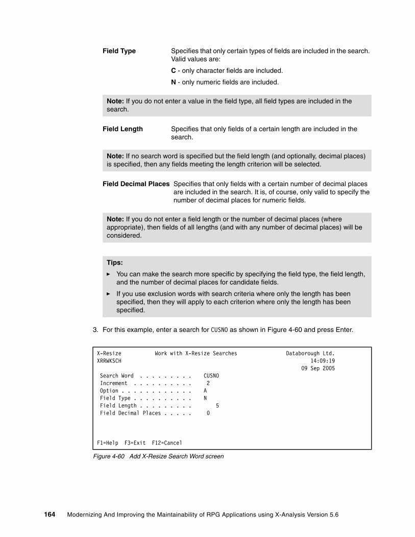
Field Type Specifies that only certain types of fields are included in the search. Valid values are:
C - only character fields are included.
N - only numeric fields are included.
Field Length Specifies that only fields of a certain length are included in the search.
Field Decimal Places Specifies that only fields with a certain number of decimal places are included in the search. It is, of course, only valid to specify the number of decimal places for numeric fields.
3. For this example, enter a search for CUSNO as shown in Figure 4-60 and press Enter.
Figure 4-60 Add X-Resize Search Word screen
Note: If you do not enter a value in the field type, all field types are included in the search.
Note: If no search word is specified but the field length (and optionally, decimal places) is specified, then any fields meeting the length criterion will be selected.
Note: If you do not enter a field length or the number of decimal places (where appropriate), then fields of all lengths (and with any number of decimal places) will be considered.
Tips:
� You can make the search more specific by specifying the field type, the field length, and the number of decimal places for candidate fields.
� If you use exclusion words with search criteria where only the length has been specified, then they will apply to each criterion where only the length has been specified.
X-Resize Work with X-Resize Searches Databorough Ltd. XRRWKSCH 14:09:19 09 Sep 2005 Search Word . . . . . . . . . CUSNO Increment . . . . . . . . . . 2 Option . . . . . . . . . . . . A Field Type . . . . . . . . . . N Field Length . . . . . . . . . 5 Field Decimal Places . . . . . 0
F1=Help F3=Exit F12=Cancel
164 Modernizing And Improving the Maintainability of RPG Applications using X-Analysis Version 5.6
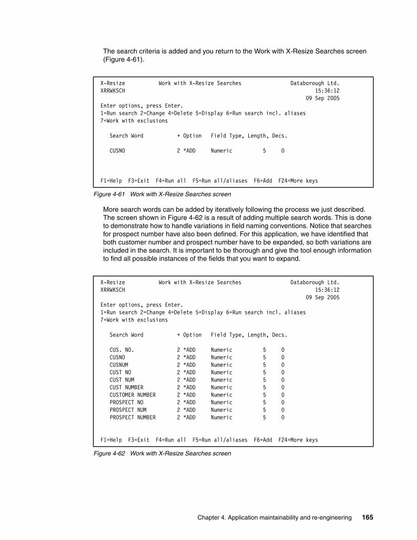
The search criteria is added and you return to the Work with X-Resize Searches screen (Figure 4-61).
Figure 4-61 Work with X-Resize Searches screen
More search words can be added by iteratively following the process we just described. The screen shown in Figure 4-62 is a result of adding multiple search words. This is done to demonstrate how to handle variations in field naming conventions. Notice that searches for prospect number have also been defined. For this application, we have identified that both customer number and prospect number have to be expanded, so both variations are included in the search. It is important to be thorough and give the tool enough information to find all possible instances of the fields that you want to expand.
Figure 4-62 Work with X-Resize Searches screen
X-Resize Work with X-Resize Searches Databorough Ltd. XRRWKSCH 15:36:12 09 Sep 2005 Enter options, press Enter. 1=Run search 2=Change 4=Delete 5=Display 6=Run search incl. aliases 7=Work with exclusions Search Word + Option Field Type, Length, Decs.
CUSNO 2 *ADD Numeric 5 0
F1=Help F3=Exit F4=Run all F5=Run all/aliases F6=Add F24=More keys
X-Resize Work with X-Resize Searches Databorough Ltd. XRRWKSCH 15:36:12 09 Sep 2005 Enter options, press Enter. 1=Run search 2=Change 4=Delete 5=Display 6=Run search incl. aliases 7=Work with exclusions Search Word + Option Field Type, Length, Decs. CUS. NO. 2 *ADD Numeric 5 0 CUSNO 2 *ADD Numeric 5 0 CUSNUM 2 *ADD Numeric 5 0 CUST NO 2 *ADD Numeric 5 0 CUST NUM 2 *ADD Numeric 5 0 CUST NUMBER 2 *ADD Numeric 5 0 CUSTOMER NUMBER 2 *ADD Numeric 5 0 PROSPECT NO 2 *ADD Numeric 5 0 PROSPECT NUM 2 *ADD Numeric 5 0 PROSPECT NUMBER 2 *ADD Numeric 5 0
F1=Help F3=Exit F4=Run all F5=Run all/aliases F6=Add F24=More keys
Chapter 4. Application maintainability and re-engineering 165

Setting up search exclusionsYou can also enter exclusion words against a specific search word to indicate that the search is invalid if the exclusion word is also present. Although you do not specify any search exclusions in this example, we now look at the Work with Search Exclusion screens:
1. At the Work with X-Resize Searches screen, select option 7 (Work with exclusions) next to the search word (CUSNO) and press Enter.
2. The Work with X-Resize Search Exclusions screen appears. Press F6 (Add) at this screen to display the screen from which to add a new search exclusion.
3. The screen used to add search exclusions appears (Figure 4-63). From here you would specify exclusion words to indicate that although the search has found a match, the search should be discounted if the exclusion word is also present. You are not adding a search exclusion in this example, so press F12 (Cancel) twice to return to the Work with X-Resize Search Screen.
Figure 4-63 Add X-Resize Search Exclusion screen
Running the searchAfter entering the words to search, you can run the search.
1. At the Work with X-Resize Searches screen, press F5 to run the search of all specified search words. As an alternative method, you can select option 6 next to each search word and press Enter. A batch job to perform the word search is submitted.
2. Press F12 to return to the Work with X-Resize Projects screen.
X-Resize Work with X-Resize Search Exclusions Databorough Ltd. XRRWKSHX 14:33:30 09 Sep 2005 Search Word . . . . . . . . . CUSNO Exclusion Word . . . . . . . . TEST
F1=Help F3=Exit F12=Cancel
Tip: To determine whether the batch job has completed, press F15 (DSPMSG) at the Work with X-Resize Searches screen. You can also work with the submitted job by pressing F14 (WRKSBMJOB) at this screen. These function keys are provided at this screen so that you do not have to exit the tool and return to the OS/400 command line.
166 Modernizing And Improving the Maintainability of RPG Applications using X-Analysis Version 5.6

3. When the batch job has completed, you see the results of the search. At the Work with X-Resize Projects screen, press F8 (All/selected) to toggle the view from all files to fields selected by the search. All fields matching the search are presented. Notice in Figure 4-64 that the field length has automatically been incremented (from 5 to 7) under the New Vals column.
Figure 4-64 Work with X-Resize Project Fields screen
4.6.4 Explicitly identifying fields to changeAnother method for identifying fields to change is to explicitly change the field lengths at the Work with Project Fields screen. This is a more manual process as it requires you to scroll through the list of fields in the cross-reference database, locate each of the fields to change, and change them. To be thorough, you could use both methods (field searching and changing fields) but in general, searches should be used to avoid having to identify each individual field manually.
Displaying global usage of a selected fieldPrior to identifying the fields to resize, you may need to gather more information about the fields and files being used. To display field usage information:
1. At the Work with X-Resize Project Fields screen, select option 6 (Field usage) next to the CUSNO field and press Enter.
X-Resize Work with X-Resize Project Fields Databorough Ltd.XRRWKFLD 15:33:50 09 Sep 2005Position on: Enter options, press Enter. 2=Change 4=Delete 5=Display 6=Field usage 7=File usage Field File Curr. Vals New Vals Field text... CNACUST CNPHSD 3 5 0 4 7 0 CUSTOMER NUMBER CNACUST CNPHST 3 5 0 4 7 0 CUSTOMER NUMBER CNVCUST CNPCNS 3 5 0 4 7 0 CUSTOMER NUMBER CUCCCUST CUTCON 3 5 0 4 7 0 CUSTOMER NUMBER CUCCUST CUTMST 3 5 0 4 7 0 CUSTOMER NUMBER CUCLCUST CUTCLC 3 5 0 4 7 0 CUSTOMER NUMBER CUCSCUST CUTSLM 3 5 0 4 7 0 CUSTOMER NUMBER CUCSCUST CUTSRI 3 5 0 4 7 0 CUSTOMER NUMBER CUSNO CNTACS 3 5 0 4 7 0 Cus. No. CUSNO CUSF 3 5 0 4 7 0 Cus. No. CUSNO CUSTS 3 5 0 4 7 0 Prospect No + F1=Help F3=Exit F6=Add F7=File/field sequence F24=More keys
Chapter 4. Application maintainability and re-engineering 167

2. A window displaying field usage information for the specified field appears (Figure 4-65). The three columns in this window show:
– The sequence number of the source file member containing the field reference.
– The name of the source file member containing the field reference.
– The first 40 characters of the actual source file member statement that contains the field reference.
From this window, you can jump to a summary view of the field usage information. To do this, type *SUMMARY in the input field following Level: (right upper corner of screen) and press Enter.
Figure 4-65 X-Resize Project Field usage detail screen
3. A window displaying field usage information for the specified field appears (Figure 4-66). The four columns in this window show:
– The sequence number of .00 (because this is a summary level view).
– The name of the source file member containing the field reference.
– The name of the source file containing the member.
– The name of the library that contains the source file.
Press F12 to return to the Work with X-Resize Project Fields screen.
Figure 4-66 X-Resize Project Field usage summary screen
Variable Where Used: CUSNO Level: *DETAIL 4.00 CLET DCL VAR(&CUSNO) TYPE(*DEC 9.00 CLET CHGVAR &CUSNO &CUSNC 10.00 CLET CALL LETN1 (&CUSNO &PREFIX &LETS 1.00 CLETN PGM PARM(&CUSNO &PREFIX & 3.00 CLETN DCL VAR(&CUSNO) TYPE(*DEC 10.00 CLETN CALL LETN1 (&CUSNO &PREFIX &LLET 3.00 CNTACS A CUSNO 5P 0 T 21.00 CNTACS A K CUSNO 97.00 CNTCMAINT C eval zcusno = c 116.00 CNTCMAINT C eval cusno = zc +
Variable Where Used: CUSNO Level: *SUMMARY .00 CLET QCLSRC XRAPPSGC .00 CLETN QCLSRC XRAPPSGC .00 CNTACS QDDSSRC XRAPPSGC .00 CNTCMAINT QRPGLESRC XRAPPSGC .00 CNTLF3 QDDSSRC XRAPPSGC .00 CNTLF4 QDDSSRC XRAPPSGC .00 CPDM QCLSRC XRAPPSGC .00 CSEC QCLSRC XRAPPSGC .00 CSEC2 QCLSRC XRAPPSGC .00 CUSCPY QRPGSRC XRAPPSGC +
168 Modernizing And Improving the Maintainability of RPG Applications using X-Analysis Version 5.6
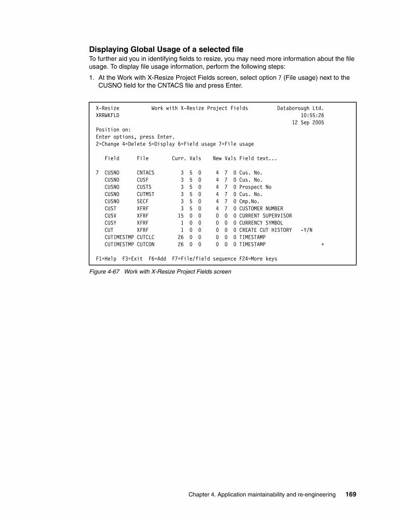
Displaying Global Usage of a selected fileTo further aid you in identifying fields to resize, you may need more information about the file usage. To display file usage information, perform the following steps:
1. At the Work with X-Resize Project Fields screen, select option 7 (File usage) next to the CUSNO field for the CNTACS file and press Enter.
Figure 4-67 Work with X-Resize Project Fields screen
X-Resize Work with X-Resize Project Fields Databorough Ltd. XRRWKFLD 10:55:26 12 Sep 2005 Position on: Enter options, press Enter. 2=Change 4=Delete 5=Display 6=Field usage 7=File usage Field File Curr. Vals New Vals Field text... 7 CUSNO CNTACS 3 5 0 4 7 0 Cus. No. CUSNO CUSF 3 5 0 4 7 0 Cus. No. CUSNO CUSTS 3 5 0 4 7 0 Prospect No CUSNO CUTMST 3 5 0 4 7 0 Cus. No. CUSNO SECF 3 5 0 4 7 0 Cmp.No. CUST XFRF 3 5 0 4 7 0 CUSTOMER NUMBER CUSV XFRF 15 0 0 0 0 0 CURRENT SUPERVISOR CUSY XFRF 1 0 0 0 0 0 CURRENCY SYMBOL CUT XFRF 1 0 0 0 0 0 CREATE CUT HISTORY -Y/N CUTIMESTMP CUTCLC 26 0 0 0 0 0 TIMESTAMP CUTIMESTMP CUTCON 26 0 0 0 0 0 TIMESTAMP + F1=Help F3=Exit F6=Add F7=File/field sequence F24=More keys
Chapter 4. Application maintainability and re-engineering 169
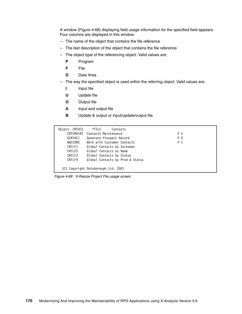
A window (Figure 4-68) displaying field usage information for the specified field appears. Four columns are displayed in this window:
– The name of the object that contains the file reference
– The text description of the object that contains the file reference
– The object type of the referencing object. Valid values are:
P Program
F File
D Data Area
– The way the specified object is used within the referring object. Valid values are:
I Input file
U Update file
O Output file
A Input and output file
B Update & output or input/update/output file
Figure 4-68 X-Resize Project File usage screen
Object: CNTACS *FILE Contacts CNTCMAINT Contacts Maintenance P U GCNTAC1 Generate Prospect Record P O WWCCONS Work with Customer Contacts P I CNTLF1 Global Contacts by Salesman CNTLF2 Global Contacts by Name CNTLF3 Global Contacts by Status CNTLF4 Global Contacts by Prod & Status (C) Copyright Databorough Ltd. 2001
170 Modernizing And Improving the Maintainability of RPG Applications using X-Analysis Version 5.6
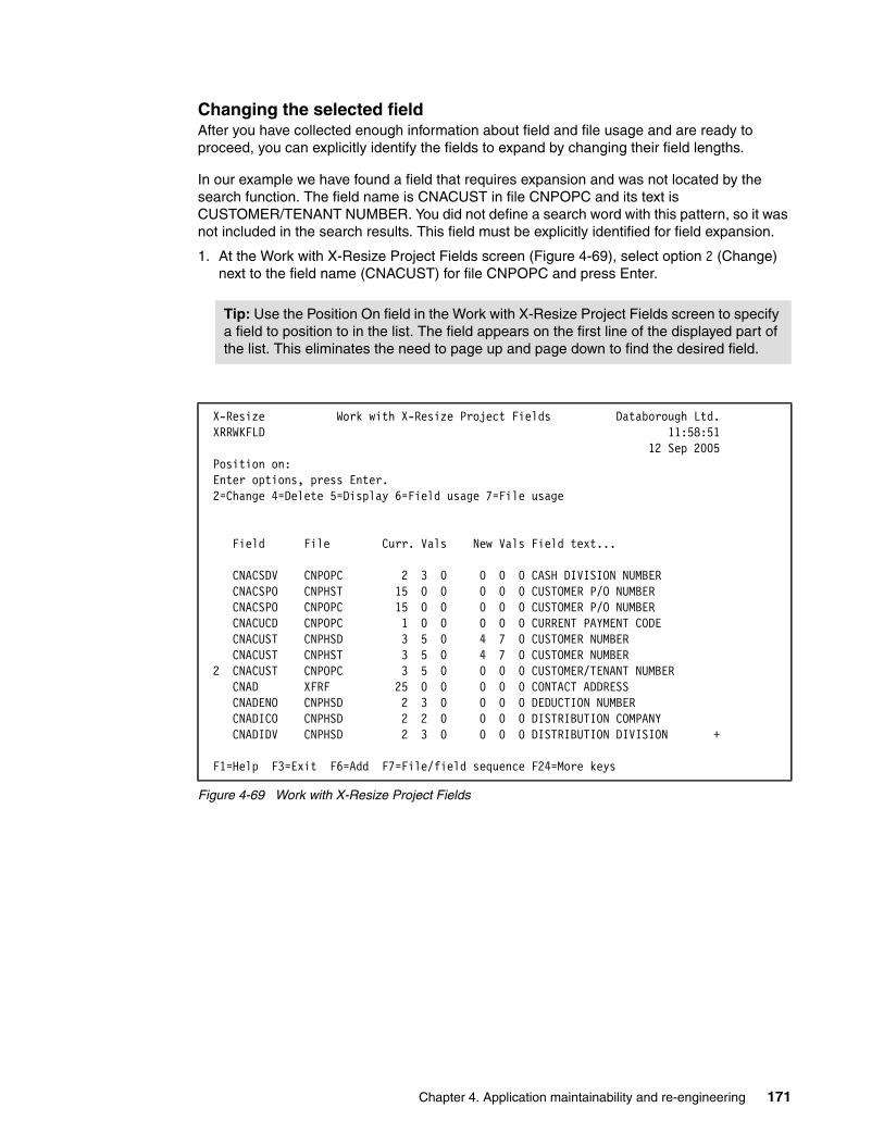
Changing the selected fieldAfter you have collected enough information about field and file usage and are ready to proceed, you can explicitly identify the fields to expand by changing their field lengths.
In our example we have found a field that requires expansion and was not located by the search function. The field name is CNACUST in file CNPOPC and its text is CUSTOMER/TENANT NUMBER. You did not define a search word with this pattern, so it was not included in the search results. This field must be explicitly identified for field expansion.
1. At the Work with X-Resize Project Fields screen (Figure 4-69), select option 2 (Change) next to the field name (CNACUST) for file CNPOPC and press Enter.
Figure 4-69 Work with X-Resize Project Fields
Tip: Use the Position On field in the Work with X-Resize Project Fields screen to specify a field to position to in the list. The field appears on the first line of the displayed part of the list. This eliminates the need to page up and page down to find the desired field.
X-Resize Work with X-Resize Project Fields Databorough Ltd. XRRWKFLD 11:58:51 12 Sep 2005 Position on: Enter options, press Enter. 2=Change 4=Delete 5=Display 6=Field usage 7=File usage Field File Curr. Vals New Vals Field text... CNACSDV CNPOPC 2 3 0 0 0 0 CASH DIVISION NUMBER CNACSPO CNPHST 15 0 0 0 0 0 CUSTOMER P/O NUMBER CNACSPO CNPOPC 15 0 0 0 0 0 CUSTOMER P/O NUMBER CNACUCD CNPOPC 1 0 0 0 0 0 CURRENT PAYMENT CODE CNACUST CNPHSD 3 5 0 4 7 0 CUSTOMER NUMBER CNACUST CNPHST 3 5 0 4 7 0 CUSTOMER NUMBER 2 CNACUST CNPOPC 3 5 0 0 0 0 CUSTOMER/TENANT NUMBER CNAD XFRF 25 0 0 0 0 0 CONTACT ADDRESS CNADENO CNPHSD 2 3 0 0 0 0 DEDUCTION NUMBER CNADICO CNPHSD 2 2 0 0 0 0 DISTRIBUTION COMPANY CNADIDV CNPHSD 2 3 0 0 0 0 DISTRIBUTION DIVISION + F1=Help F3=Exit F6=Add F7=File/field sequence F24=More keys
Chapter 4. Application maintainability and re-engineering 171

2. The screen to change the project field appears. Type 7 for the New Length value (Figure 4-70) and press Enter.
Figure 4-70 Change X-Resize Project Field
The record is changed and you are returned to the Work with X-Resize Project Fields screen (Figure 4-71).
Figure 4-71 Work with X-Resize Project Fields
X-Resize Work with X-Resize Project Fields Databorough Ltd. XRRWKFLD 11:58:51 12 Sep 2005 File . . . . . . . . . . . . . CNPOPC Field . . . . . . . . . . . . CNACUST Current Length . . . . . . . . 5 Current Decimal Positions . . 0 New Length . . . . . . . . . . 7 New Decimal Positions . . . . 0 Field Type . . . . . . . . . . P Field Text . . . . . . . . . . CUSTOMER/TENANT NUMBER Column Heading 1 . . . . . . . CUST# Column Heading 2 . . . . . . . Column Heading 3 . . . . . . . Internal Field Name . . . . . CNACUST Field Alias . . . . . . . . . F1=Help F3=Exit F12=Cancel
X-Resize Work with X-Resize Project Fields Databorough Ltd. XRRWKFLD 11:58:51 12 Sep 2005 Position on: Enter options, press Enter. 2=Change 4=Delete 5=Display 6=Field usage 7=File usage Field File Curr. Vals New Vals Field text... CNACSDV CNPOPC 2 3 0 0 0 0 CASH DIVISION NUMBER CNACSPO CNPHST 15 0 0 0 0 0 CUSTOMER P/O NUMBER CNACSPO CNPOPC 15 0 0 0 0 0 CUSTOMER P/O NUMBER CNACUCD CNPOPC 1 0 0 0 0 0 CURRENT PAYMENT CODE CNACUST CNPHSD 3 5 0 4 7 0 CUSTOMER NUMBER CNACUST CNPHST 3 5 0 4 7 0 CUSTOMER NUMBER CNACUST CNPOPC 3 5 0 4 7 0 CUSTOMER/TENANT NUMBER CNAD XFRF 25 0 0 0 0 0 CONTACT ADDRESS CNADENO CNPHSD 2 3 0 0 0 0 DEDUCTION NUMBER CNADICO CNPHSD 2 2 0 0 0 0 DISTRIBUTION COMPANY CNADIDV CNPHSD 2 3 0 0 0 0 DISTRIBUTION DIVISION + F1=Help F3=Exit F6=Add F7=File/field sequence F24=More keys Record changed.
172 Modernizing And Improving the Maintainability of RPG Applications using X-Analysis Version 5.6

Displaying all fields identified for field expansionAt this point you have (via the two methods) identified all fields to be expanded. You can view a list of the fields from the Work with X-Resize Project Fields by using the F8 Toggle function:
1. At the Work with X-Resize Project Fields screen, press F8 (All/selected).
Notice that the contents of the list (Figure 4-72) have changed. Prior to pressing F8, all fields in the cross-reference library were displayed. Now only those found by the search or that have explicitly changed appear on the screen.
Also notice that each value in the Curr. Vals columns is 3,5,0 (3 for the buffer length, 5 for field length, 0 for decimal positions) and in New Vals it is 4,7,0. This change in the field length determines what is shown in the list. All fields that have new values that differ from their current values are displayed. In the case of those identified by the search, their new value was incremented from 5 to 7 automatically. You explicitly changed the length of the CNACUST field in the CNPOPC file.
Figure 4-72 Work with X-Resize Project Fields
2. Press F8 again to toggle back to displaying all fields in the cross-reference repository.
3. Press F12 to return to the Work with X-Resize Projects screen.
X-Resize Work with X-Resize Project Fields Databorough Ltd. XRRWKFLD 11:58:51 12 Sep 2005 Position on: Enter options, press Enter. 2=Change 4=Delete 5=Display 6=Field usage 7=File usage Field File Curr. Vals New Vals Field text... CNACUST CNPHSD 3 5 0 4 7 0 CUSTOMER NUMBER CNACUST CNPHST 3 5 0 4 7 0 CUSTOMER NUMBER CNACUST CNPOPC 3 5 0 4 7 0 CUSTOMER/TENANT NUMBER CNVCUST CNPCNS 3 5 0 4 7 0 CUSTOMER NUMBER CUCCCUST CUTCON 3 5 0 4 7 0 CUSTOMER NUMBER CUCCUST CUTMST 3 5 0 4 7 0 CUSTOMER NUMBER CUCLCUST CUTCLC 3 5 0 4 7 0 CUSTOMER NUMBER CUCSCUST CUTSLM 3 5 0 4 7 0 CUSTOMER NUMBER CUCSCUST CUTSRI 3 5 0 4 7 0 CUSTOMER NUMBER CUSNO CNTACS 3 5 0 4 7 0 Cus. No. CUSNO CUSF 3 5 0 4 7 0 Cus. No. + F8=All/selected F10=Cmd line F12=Cancel F14=WRKSBMJOB F24=More keys
Chapter 4. Application maintainability and re-engineering 173
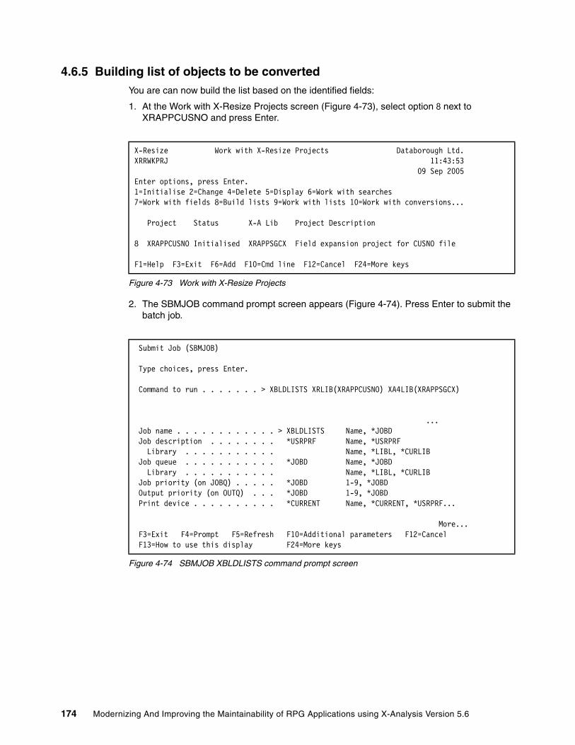
4.6.5 Building list of objects to be convertedYou are can now build the list based on the identified fields:
1. At the Work with X-Resize Projects screen (Figure 4-73), select option 8 next to XRAPPCUSNO and press Enter.
Figure 4-73 Work with X-Resize Projects
2. The SBMJOB command prompt screen appears (Figure 4-74). Press Enter to submit the batch job.
Figure 4-74 SBMJOB XBLDLISTS command prompt screen
X-Resize Work with X-Resize Projects Databorough Ltd. XRRWKPRJ 11:43:53 09 Sep 2005 Enter options, press Enter. 1=Initialise 2=Change 4=Delete 5=Display 6=Work with searches 7=Work with fields 8=Build lists 9=Work with lists 10=Work with conversions... Project Status X-A Lib Project Description 8 XRAPPCUSNO Initialised XRAPPSGCX Field expansion project for CUSNO file
F1=Help F3=Exit F6=Add F10=Cmd line F12=Cancel F24=More keys
Submit Job (SBMJOB) Type choices, press Enter. Command to run . . . . . . . > XBLDLISTS XRLIB(XRAPPCUSNO) XA4LIB(XRAPPSGCX)
... Job name . . . . . . . . . . . . > XBLDLISTS Name, *JOBD Job description . . . . . . . . *USRPRF Name, *USRPRF Library . . . . . . . . . . . Name, *LIBL, *CURLIB Job queue . . . . . . . . . . . *JOBD Name, *JOBD Library . . . . . . . . . . . Name, *LIBL, *CURLIB Job priority (on JOBQ) . . . . . *JOBD 1-9, *JOBD Output priority (on OUTQ) . . . *JOBD 1-9, *JOBD Print device . . . . . . . . . . *CURRENT Name, *CURRENT, *USRPRF... More... F3=Exit F4=Prompt F5=Refresh F10=Additional parameters F12=Cancel F13=How to use this display F24=More keys
174 Modernizing And Improving the Maintainability of RPG Applications using X-Analysis Version 5.6

The command XBLDLISTS is submitted to batch. When the job completes, the status for the project changes to Lists built (Figure 4-75).
Figure 4-75 Work with X-Resize Projects
Tip: To determine whether the batch job has completed, press F15 (DSPMSG) at the Work with X-Resize Searches screen. To work with the submitted job, press F14 (WRKSBMJOB) from this screen. These function keys are provided for this screen so that you do not have to exit the tool and return to the OS/400 command line.
X-Resize Work with X-Resize Projects Databorough Ltd. XRRWKPRJ 10:43:40 12 Sep 2005 Enter options, press Enter. 1=Initialise 2=Change 4=Delete 5=Display 6=Work with searches 7=Work with fields 8=Build lists 9=Work with lists 10=Work with conversions... Project Status X-A Lib Project Description XRAPPCUSNO Lists built XRAPPSGCX Field expansion project for CUSNO file
F1=Help F3=Exit F6=Add F10=Cmd line F12=Cancel F24=More keys
Chapter 4. Application maintainability and re-engineering 175
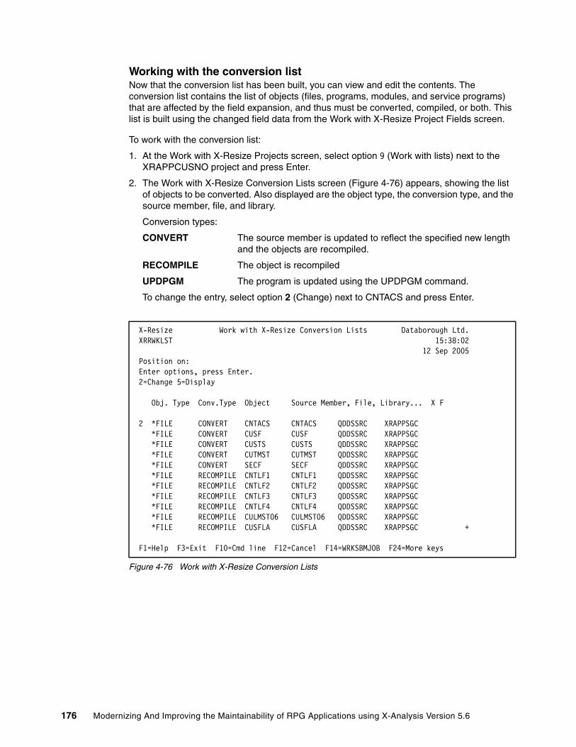
Working with the conversion listNow that the conversion list has been built, you can view and edit the contents. The conversion list contains the list of objects (files, programs, modules, and service programs) that are affected by the field expansion, and thus must be converted, compiled, or both. This list is built using the changed field data from the Work with X-Resize Project Fields screen.
To work with the conversion list:
1. At the Work with X-Resize Projects screen, select option 9 (Work with lists) next to the XRAPPCUSNO project and press Enter.
2. The Work with X-Resize Conversion Lists screen (Figure 4-76) appears, showing the list of objects to be converted. Also displayed are the object type, the conversion type, and the source member, file, and library.
Conversion types:
CONVERT The source member is updated to reflect the specified new length and the objects are recompiled.
RECOMPILE The object is recompiled
UPDPGM The program is updated using the UPDPGM command.
To change the entry, select option 2 (Change) next to CNTACS and press Enter.
Figure 4-76 Work with X-Resize Conversion Lists
X-Resize Work with X-Resize Conversion Lists Databorough Ltd. XRRWKLST 15:38:02 12 Sep 2005 Position on: Enter options, press Enter. 2=Change 5=Display
Obj. Type Conv.Type Object Source Member, File, Library... X F 2 *FILE CONVERT CNTACS CNTACS QDDSSRC XRAPPSGC *FILE CONVERT CUSF CUSF QDDSSRC XRAPPSGC *FILE CONVERT CUSTS CUSTS QDDSSRC XRAPPSGC *FILE CONVERT CUTMST CUTMST QDDSSRC XRAPPSGC *FILE CONVERT SECF SECF QDDSSRC XRAPPSGC *FILE RECOMPILE CNTLF1 CNTLF1 QDDSSRC XRAPPSGC *FILE RECOMPILE CNTLF2 CNTLF2 QDDSSRC XRAPPSGC *FILE RECOMPILE CNTLF3 CNTLF3 QDDSSRC XRAPPSGC *FILE RECOMPILE CNTLF4 CNTLF4 QDDSSRC XRAPPSGC *FILE RECOMPILE CULMST06 CULMST06 QDDSSRC XRAPPSGC *FILE RECOMPILE CUSFLA CUSFLA QDDSSRC XRAPPSGC + F1=Help F3=Exit F10=Cmd line F12=Cancel F14=WRKSBMJOB F24=More keys
176 Modernizing And Improving the Maintainability of RPG Applications using X-Analysis Version 5.6

3. The screen to change the conversion list object appears (Figure 4-77). From this screen, you can change two fields: Excluded and Reference Type.
Excluded Specify “Y” to exclude the object from the conversion.
Reference Type Specify:
• F indicates that the object is a field reference file. These files are compiled first.
• R indicates that the file is some other reference file. These files are compiled next followed by all other files.
For this example, there are no changes to those fields. Press Enter.
Figure 4-77 Change conversion list entry screen
4.6.6 Running a conversionWhen all of the problems highlighted by the diagnostic reports have been addressed, you are ready to proceed with the conversion stage of the project. The complete conversion process contains the following stages:
1. Convert fields: The field definitions in the source members for the database files are converted.
2. Recompile files: The database files are recompiled.
3. Update files: The data is copied and mapped from the original database files to the converted database files.
4. Convert programs: Programs, service programs, and modules and any device files used by them are converted.
5. Recompile programs: Programs, service programs, and modules and any device files used by them are recompiled. (For ILE RPG programs and service programs, the modules are recompiled and the programs are updated.)
6. Reattach triggers: Any trigger programs attached to the original database files are attached to the converted database files.
The conversion can be run to completion in one step (using option 1 from the Work with X-Resize Conversion screen) or it can be broken down into incremental steps. In most environments, it is neither advisable or practical to run the conversion in one step. This is because most production environments are complex and require multiple levels of change management control. Successfully implementing a field re-engineering project in one step is not feasible due to the complex nature of most production environments.
X-Resize Work with X-Resize Conversion Lists Databorough Ltd. XRRWKLST 13:33:51 12 Sep 2005 Object Type . . . . . . . . . *FILE Conversion Type . . . . . . . CONVERT Object . . . . . . . . . . . . CNTACS Source Member . . . . . . . . CNTACS Source File . . . . . . . . . QDDSSRC Source Library . . . . . . . . XRAPPSGC Source Type . . . . . . . . . PF Excluded . . . . . . . . . . . Reference Type . . . . . . . .
F1=Help F3=Exit F12=Cancel
Chapter 4. Application maintainability and re-engineering 177

A more practical approach is to conduct the conversion process in individual steps.
1. Set up conversion.
2. Conduct recompile of files and programs only.
3. Run field conversions and recompile objects.
a. Convert fields and recompile files.
b. Convert programs and recompile programs.
4. Perform analysis.
5. Import converted library into change management system.
Setting up a conversionTo set up a conversion, perform the following steps:
1. At the Work with X-Resize Projects screen, select option 10 (Work with conversions) next to the XRAPPCUSNO project and press Enter.
2. The Work with X-Resize Conversions screen appears (Figure 4-78). Press F6 (Add) to create a new conversion.
Figure 4-78 Work with X-Resize Conversions screen
3. The screen to add a new conversion record is displayed. The following information can be entered at this screen:
Conversion Library The conversion library name should be the name of a new library, X-Resize creates specifically for this purpose.
Conversion Description Any descriptive text required.
Conversion Type The conversion type can be either:
*REPLACE Replace the current source line with an amended one.
*ADD Comment out the current source line and add a new amended) one immediately after it.
Notation type The notation type can be one of the following
MARGIN Flag a changed source line in positions 1 to 5. The default value is XRSZE, however, you can specify any value using the data area XRMARGIN in the project library.
COMMENT Flag a changed source line with a comment immediately preceding it.
X-Resize Work with X-Resize Conversions Databorough Ltd. XRRWKCNV 16:03:00 12 Sep 2005 Enter options, press Enter. 1=Run complete conversion 2=Change 4=Delete 5=Display 6=Convert fields 7=Recompile files 8=Update files 9=Convert programs 10=Recompile programs... Conversion Description Type Progress
F1=Help F3=Exit F6=Add F10=Cmd line F12=Cancel F24=More keys
178 Modernizing And Improving the Maintainability of RPG Applications using X-Analysis Version 5.6
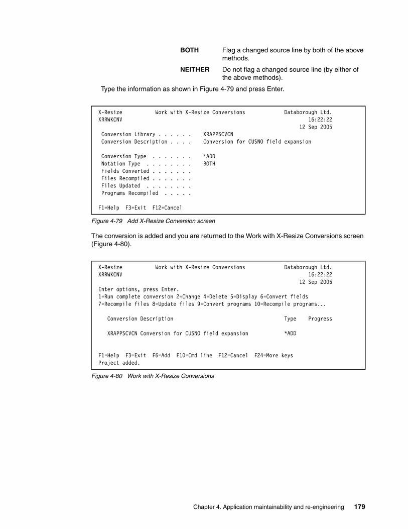
BOTH Flag a changed source line by both of the above methods.
NEITHER Do not flag a changed source line (by either of the above methods).
Type the information as shown in Figure 4-79 and press Enter.
Figure 4-79 Add X-Resize Conversion screen
The conversion is added and you are returned to the Work with X-Resize Conversions screen (Figure 4-80).
Figure 4-80 Work with X-Resize Conversions
X-Resize Work with X-Resize Conversions Databorough Ltd. XRRWKCNV 16:22:22 12 Sep 2005 Conversion Library . . . . . . XRAPPSCVCN Conversion Description . . . . Conversion for CUSNO field expansion Conversion Type . . . . . . . *ADD Notation Type . . . . . . . . BOTH Fields Converted . . . . . . . Files Recompiled . . . . . . . Files Updated . . . . . . . . Programs Recompiled . . . . .
F1=Help F3=Exit F12=Cancel
X-Resize Work with X-Resize Conversions Databorough Ltd. XRRWKCNV 16:22:22 12 Sep 2005 Enter options, press Enter. 1=Run complete conversion 2=Change 4=Delete 5=Display 6=Convert fields 7=Recompile files 8=Update files 9=Convert programs 10=Recompile programs... Conversion Description Type Progress XRAPPSCVCN Conversion for CUSNO field expansion *ADD
F1=Help F3=Exit F6=Add F10=Cmd line F12=Cancel F24=More keys Project added.
Chapter 4. Application maintainability and re-engineering 179

Conducting recompile only exerciseAt this stage, the X-Resize tool has identified what objects need be changed. Prior to converting the fields and applying any changes in the source code, you need to conduct a baseline test to establish whether any compile issues exist. This baseline test helps eliminate time wasted by trying to track down and resolves issues that existed previously and are not the result of the field expansion.
An example of this is a program that contains a reference to the expanded field (and thus was included in the build list), but cannot compile due to a missing logical file that it references. It could not be compiled prior to field expansion or afterwards. Any time spent trying to investigate and resolve this is beyond the scope of our field expansion effort.
To perform the baseline test:
1. Follow the steps described in “Setting up a conversion” on page 178 to create another X-Resize conversion (which we call XRAPPSTEST).
2. At the Work with X-Resize Conversions, select option 7 (Recompile files) next to the XRAPPSTEST conversion and press Enter (Figure 4-81).
Figure 4-81 Work with X-Resize Conversions
3. A job to recompile the files is submitted to batch. When this job completes, select option 10 (Recompile programs) next to the XRAPPSTEST conversion and press Enter.
A job to recompile the programs is submitted to batch. As a result of the previous two steps, two physical files were created in library XRAPPSTEST:
XRRCFERR Contains a list of all files that encountered errors during compilation and could not be compiled.
XRRCVERR Contains a list of all programs that encountered errors during compilation and could not be compiled.
These activities produce a list of files and programs that could not be compiled prior to field conversion. You can use these two files later in the process to determine what files and programs to ignore when performing problem determination after an actual conversion.
X-Resize Work with X-Resize Conversions Databorough Ltd. XRRWKCNV 12:00:28 15 Sep 2005 Enter options, press Enter. 1=Run complete conversion 2=Change 4=Delete 5=Display 6=Convert fields 7=Recompile files 8=Update files 9=Convert programs 10=Recompile programs... Conversion Description Type Progress XRAPPSCVCN Conversion for CUSNO field expansion *ADD Y Y Y Y 7 XRAPPSTEST Baseline test for XRAPPS conversion *ADD
F1=Help F3=Exit F6=Add F10=Cmd line F12=Cancel F24=More keys Project added.
180 Modernizing And Improving the Maintainability of RPG Applications using X-Analysis Version 5.6

Running field conversions and recompiling objectsWith the conversion set up, you can convert the fields:
1. At the Work with X-Resize Conversions screen (Figure 4-82), select option 6 (Convert fields) next to the XRAPPSCVCN conversion and press Enter.
The job XCVTFIELDS to convert the fields is submitted to batch. This job converts the field definitions in the source members for all of the identified database files. Monitor the progress of this job to verify that it completes successfully.
Figure 4-82 Work with X-Resize Conversions
2. When the batch job to convert the fields completes successfully, select option 7 (Recompile files) next to the XRAPPSTEST conversion and press Enter. A job to recompile the files is submitted to batch.
3. When the job to recompile the files, successfully completes, select option 9 (Convert programs) next to the XRAPPSTEST conversion (Figure 4-83) and press Enter.
Figure 4-83 SBMJOB command prompt screen
4. The SBMJOB command prompt screen appears. Make sure your cursor is on the Command to run parameter and press F4.
X-Resize Work with X-Resize Conversions Databorough Ltd. XRRWKCNV 16:22:22 12 Sep 2005 Enter options, press Enter. 1=Run complete conversion 2=Change 4=Delete 5=Display 6=Convert fields 7=Recompile files 8=Update files 9=Convert programs 10=Recompile programs... Conversion Description Type Progress 6 XRAPPSCVCN Conversion for CUSNO field expansion *ADD
Submit Job (SBMJOB) Type choices, press Enter. Command to run . . . . . . . . . > XCVTPGMS XRLIB(XRAPPCUSNO) XA4LIB(XRAPPSGCX) CVLIB(XRAPPSCVCN) CVTTYPE(*ADD) NOTETYPE(*BOTH) NOTEVAL(XRSZE)
... Job name . . . . . . . . . . . . > XCVTPGMS Name, *JOBD Job description . . . . . . . . *USRPRF Name, *USRPRF Library . . . . . . . . . . . Name, *LIBL, *CURLIB Job queue . . . . . . . . . . . *JOBD Name, *JOBD Library . . . . . . . . . . . Name, *LIBL, *CURLIB Job priority (on JOBQ) . . . . . *JOBD 1-9, *JOBD Output priority (on OUTQ) . . . *JOBD 1-9, *JOBD Print device . . . . . . . . . . *CURRENT Name, *CURRENT, *USRPRF... More... F3=Exit F4=Prompt F5=Refresh F10=Additional parameters F12=Cancel F13=How to use this display F24=More keys
Chapter 4. Application maintainability and re-engineering 181

5. The XCVTPGMS (Convert Programs) command prompt screen (Figure 4-84) appears. From here you can change the values of the Line Conversion Type and Annotation Type values that were discussed previously. In addition, you can change the Annotation Value parameter. This value marks converted source code. You can enter a value of your choice, or leave the default value of *DFT. If you specify *DFT, the system will use the value from data area XRMARGIN. Press Enter twice.
Figure 4-84 Convert Programs command prompt screen
6. A job to convert the programs fields is submitted to batch. This job converts the identified fields, variables, and other previously described constructs for all identified programs, modules, and any device files used by them. When the batch job to convert the programs has completed, select option 10 (Recompile programs) next to the XRAPPSTEST conversion and press Enter.
A job to recompile the programs is submitted to batch.
Optional stepsIf you are not using a change management system to implement the field re-engineering changes in production, you need to take the following two steps:
7. Update Files copies and maps the data from the original database files to the converted database files. Select option 8 (Update files) next to the XRAPPSTEST conversion and press Enter.
A job is submitted to batch.
8. Reattach Triggers takes any trigger programs attached to the original database files and attaches them to the converted database files. Select option 11 (Reattach triggers) next to the XRAPPSTEST conversion and press Enter.
A job to reattach the triggers is submitted to batch.
Performing analysisAfter the conversion has completed, you are ready to analyze the results of the conversion. First you verify the changes were implemented by examining the source file member changes. You also want to verify that all files and programs were compiled successfully. In this section, you verify the results of the field conversion process by examining the source file member changes of a physical file, display file, and RPG program. And you analyze the log files to determine whether the files and programs compiled successfully.
Convert Programs (XCVTPGMS) Level: 2 Type choices, press Enter. X-Resize Library . . . . . . . . > XRAPPCUSNO Name X-Analysis Library . . . . . . . > XRAPPSGCX Name, *XRLIB Conversion Library . . . . . . . > XRAPPSCVCN Name Line Conversion Type . . . . . . > *ADD *ADD, *REPLACE Annotation Type . . . . . . . . > *BOTH *MARGIN, *COMMENT, *BOTH... Annotation Value . . . . . . . . *DFT Name, *DFT
Bottom F3=Exit F4=Prompt F5=Refresh F12=Cancel F13=How to use this display F24=More keys
182 Modernizing And Improving the Maintainability of RPG Applications using X-Analysis Version 5.6

Verifying completion of conversion processTo verify that the conversion process has completed, take the following steps:
1. At the Work with X-Resize Projects screen, select option 10 (Work with conversions) next to the XRAPPCUSNO project and press Enter.
The Work with X-Resize Conversions screen (Figure 4-85) appears. Each conversion stage is displayed on the Work with X-Resize Conversions screen under the Progress columns (right column). If the stage has been completed, a Y appears in the column. Here is a description of each Progress column:
– Progress column 1: Fields converted; the source file members of all affected files have been updated to reflect the field expansion.
– Progress column 2: Files recompiled; all affected files have been recompiled.
– Progress column 3: Files updated; the data of all affected database files has been copied and mapped from the original database files to the converted database files.
– Progress column 4: Programs recompiled; all affected modules, programs, and service programs have been recompiled.
2. When all four Progress columns display Y, the conversion has completed.
Figure 4-85 Work with X-Resize Conversions screen
Verifying source code changesAs a result of the conversion process, changes were made to multiple source code members. In this section you verify some of the changes by examining the updated source file members of a physical file, display file, and RPG program.
To examine the DDS source file member changes to a physical file, perform the following steps:
1. From the Work with X-Resize Conversions screen, select option 12 (Work with conv. fields) next to the XRAPPSCVCN conversion and press Enter.
X-Resize Work with X-Resize Conversions Databorough Ltd. XRRWKCNV 16:31:42 12 Sep 2005 Enter options, press Enter. 1=Run complete conversion 2=Change 4=Delete 5=Display 6=Convert fields 7=Recompile files 8=Update files 9=Convert programs 10=Recompile programs... Conversion Description Type Progress XRAPPSCVCN Conversion for CUSNO field expansion *ADD Y Y Y Y
F1=Help F3=Exit F6=Add F10=Cmd line F12=Cancel F24=More keys
Tip: If option 12 does not appear on the Work with X-Resize Conversions screen, press F23 (More options). Pressing the key shows additional list options on the display. The options can be used even when they are not shown on the display.
Chapter 4. Application maintainability and re-engineering 183

2. The Work with Members Using PDM screen appears (Figure 4-86). Select option 5 (Display) next to the CNTACS member and press Enter.
Figure 4-86 Work with Members using PDM screen
The Source Entry Utility (SEU) is invoked and the source file member CNTACS is presented in browse mode (Figure 4-87 on page 185). The following changes were implemented automatically by the conversion process:
– Line 3 contains a comment describing the change.
– Line 4 contains the specification for field CUSNO prior to the change. The length of the field is packed 5,0. This line has been commented out, instructing the compiler to ignore it.
– Line 5 has the new specification for CUSNO. The length of the field is now packed 7,0.
Work with Members Using PDM RCHAS12 File . . . . . . QDDSSRC Library . . . . XRAPPSCVCN Position to . . . . . Type options, press Enter. 2=Edit 3=Copy 4=Delete 5=Display 6=Print 7=Rename 8=Display description 9=Save 13=Change text 14=Compile 15=Create module... Opt Member Type Text 5 CNTACS PF Contacts CNTCMAINTD DSPF Contacts Maintenance CUSF PF Sites CUSFMAINTD DSPF Customer Site Maintenance CUSFSELD DSPF Customer Site Selection CUSTS PF Purchases CUTMST PF Account Masters OE001DF DSPF Order Entry Display More... Parameters or command ===> F3=Exit F4=Prompt F5=Refresh F6=Create F9=Retrieve F10=Command entry F23=More options F24=More keys (C) COPYRIGHT IBM CORP. 1981, 2003.
184 Modernizing And Improving the Maintainability of RPG Applications using X-Analysis Version 5.6

Figure 4-87 SEU screen for CNTACS
3. Press F12 (Cancel) to return to the Work with Members Using PDM screen.
To examine the DDS source file member changes to a display file:
1. From the Work with Members Using PDM screen (Figure 4-88), select option 5 (Display) next to the CNTCMAINTD member and press Enter.
Figure 4-88 Work with Members Using PDM screen
Columns . . . : 1 71 Edit XRAPPSCVCN/QDDSSRC SEU==> CNTACS FMT A* .....A*. 1 ...+... 2 ...+... 3 ...+... 4 ...+... 5 ...+... 6 ...+... 7 *************** Beginning of data *************************************0001.00 * Active Contacts File: 0002.00 A R RCNTAC 0003.00 XRSZEA* Changed by X-RESIZE 0004.00 XRSZEA* CUSNO 5P 0 TEXT('Cus. No.') 0005.00 XRSZEA CUSNO 7P 0 TEXT('Cus. No.') 0006.00 A COLHDG('Cus.' 'No.') 0007.00 A USERNM 34A TEXT('Contact') 0008.00 A PRPCDE 2A TEXT('Product Code') 0009.00 A COLHDG('Prod' 'Code') 0010.00 A TELNO 17A TEXT('Phone') 0011.00 A FAXNO 15A TEXT('Fax.No.') 0012.00 A EMAIL 50A TEXT('Email') 0013.00 A LCTDAT 6S 0 TEXT('Last Date') 0014.00 A COLHDG('Last Cnt' 'Date') 0015.00 A EDTCDE(Y) 0016.00 A APDATE 6S 0 TEXT('Next Date')
Work with Members Using PDM RCHAS12 File . . . . . . QDDSSRC Library . . . . XRAPPSCVCN Position to . . . . . Type options, press Enter. 2=Edit 3=Copy 4=Delete 5=Display 6=Print 7=Rename 8=Display description 9=Save 13=Change text 14=Compile 15=Create module... Opt Member Type Text CNTACS PF Contacts 5 CNTCMAINTD DSPF Contacts Maintenance CUSF PF Sites CUSFMAINTD DSPF Customer Site Maintenance CUSFSELD DSPF Customer Site Selection CUSTS PF Purchases CUTMST PF Account Masters OE001DF DSPF Order Entry Display More... Parameters or command ===> F3=Exit F4=Prompt F5=Refresh F6=Create F9=Retrieve F10=Command entry F23=More options F24=More keys
Chapter 4. Application maintainability and re-engineering 185

2. SEU is invoked and the source file member CNTCMAINTD is presented in browse mode. Page down until you see the XRSZE tags (Figure 4-89). Note that the following changes were implemented automatically by the conversion process:
– Line 2.5 contains the specification for field ZCUSNO prior to the change. The length of the field is packed 5,0. This line has been commented out, thus instructing the compiler to ignore it.
– Line 2.6 contains a comment describing the change.
– Line 2.7 contains the new specification for ZCUSNO. The length of the field is now packed 7,0.
Press F12 (Cancel) to return to the Work with Members Using PDM screen.
Figure 4-89 SEU screen for CNTCMAINTD
Finally, to examine an RPG source file member change:
1. From the Work with Members Using PDM screen, change the value following File (the first input capable field on the screen, located in the top-left corner) from QDDSSRC to QRPGLESRC and press Enter.
Columns . . . : 1 71 Browse XRAPPSCVCN/QDDSSRC SEU==> CNTCMAINTD FMT DP .....AAN01N02N03T.Name++++++RLen++TDpBLinPosFunctions++++++++++++++++++ 0001.80 A 1 64'Databorough Ltd.' 0001.90 A COLOR(BLU) 0002.00 A ZZPGM 10A O 2 2TEXT('Program Name') 0002.10 A OVRDTA 0002.20 A 2 72TIME 0002.30 A ZZDATE 11A O 3 69OVRDTA 0002.40 A 4 2'Customer No . . . . . . .' 0002.50 XRSZEA* ZCUSNO 5Y 0B 4 28 0002.60 * XRSZE Line added by X-Resize 0002.70 XRSZEA ZCUSNO 7Y 0B 4 28 0002.80 A DSPATR(HI) 0002.90 A OVRDTA OVRATR 0003.00 A 31 DSPATR(PR) 0003.10 A 5 2'Product Code . . . . . .' 0003.20 A ZPRPCDE 2A B 5 28 0003.30 A DSPATR(HI) 0003.40 A OVRDTA OVRATR F3=Exit F5=Refresh F9=Retrieve F10=Cursor F11=Toggle F12=Cancel F16=Repeat find F24=More keys
186 Modernizing And Improving the Maintainability of RPG Applications using X-Analysis Version 5.6
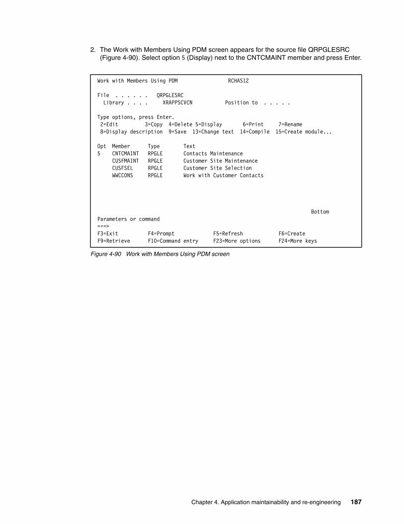
2. The Work with Members Using PDM screen appears for the source file QRPGLESRC (Figure 4-90). Select option 5 (Display) next to the CNTCMAINT member and press Enter.
Figure 4-90 Work with Members Using PDM screen
Work with Members Using PDM RCHAS12 File . . . . . . QRPGLESRC Library . . . . XRAPPSCVCN Position to . . . . . Type options, press Enter. 2=Edit 3=Copy 4=Delete 5=Display 6=Print 7=Rename 8=Display description 9=Save 13=Change text 14=Compile 15=Create module... Opt Member Type Text 5 CNTCMAINT RPGLE Contacts Maintenance CUSFMAINT RPGLE Customer Site Maintenance CUSFSEL RPGLE Customer Site Selection WWCCONS RPGLE Work with Customer Contacts Bottom Parameters or command ===> F3=Exit F4=Prompt F5=Refresh F6=Create F9=Retrieve F10=Command entry F23=More options F24=More keys
Chapter 4. Application maintainability and re-engineering 187
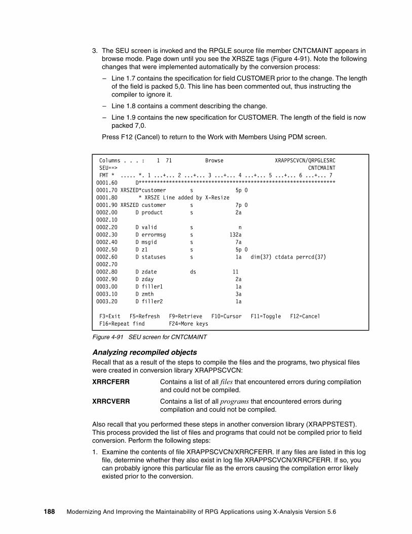
3. The SEU screen is invoked and the RPGLE source file member CNTCMAINT appears in browse mode. Page down until you see the XRSZE tags (Figure 4-91). Note the following changes that were implemented automatically by the conversion process:
– Line 1.7 contains the specification for field CUSTOMER prior to the change. The length of the field is packed 5,0. This line has been commented out, thus instructing the compiler to ignore it.
– Line 1.8 contains a comment describing the change.
– Line 1.9 contains the new specification for CUSTOMER. The length of the field is now packed 7,0.
Press F12 (Cancel) to return to the Work with Members Using PDM screen.
Figure 4-91 SEU screen for CNTCMAINT
Analyzing recompiled objectsRecall that as a result of the steps to compile the files and the programs, two physical files were created in conversion library XRAPPSCVCN:
XRRCFERR Contains a list of all files that encountered errors during compilation and could not be compiled.
XRRCVERR Contains a list of all programs that encountered errors during compilation and could not be compiled.
Also recall that you performed these steps in another conversion library (XRAPPSTEST). This process provided the list of files and programs that could not be compiled prior to field conversion. Perform the following steps:
1. Examine the contents of file XRAPPSCVCN/XRRCFERR. If any files are listed in this log file, determine whether they also exist in log file XRAPPSCVCN/XRRCFERR. If so, you can probably ignore this particular file as the errors causing the compilation error likely existed prior to the conversion.
Columns . . . : 1 71 Browse XRAPPSCVCN/QRPGLESRC SEU==> CNTCMAINT FMT * ..... *. 1 ...+... 2 ...+... 3 ...+... 4 ...+... 5 ...+... 6 ...+... 7 0001.60 D***************************************************************** 0001.70 XRSZED*customer s 5p 0 0001.80 * XRSZE Line added by X-Resize 0001.90 XRSZED customer s 7p 0 0002.00 D product s 2a 0002.10 0002.20 D valid s n 0002.30 D errormsg s 132a 0002.40 D msgid s 7a 0002.50 D z1 s 5p 0 0002.60 D statuses s 1a dim(37) ctdata perrcd(37) 0002.70 0002.80 D zdate ds 11 0002.90 D zday 2a 0003.00 D filler1 1a 0003.10 D zmth 3a 0003.20 D filler2 1a F3=Exit F5=Refresh F9=Retrieve F10=Cursor F11=Toggle F12=Cancel F16=Repeat find F24=More keys
188 Modernizing And Improving the Maintainability of RPG Applications using X-Analysis Version 5.6

2. Do the same analysis for the program log file XRAPPSCVCN/XRRCVERR. Again, eliminate any programs that could not be compiled prior to conversion.
3. After you have completed this analysis, you should have a list of all files and programs that could not be compiled due to the conversion. More involved analysis is required at some point. Find and examine the spool files generated by the compile to determine the cause of the compilation errors.
4.6.7 Identifying potential problemsIt is overly optimistic to expect the field re-engineering process to perform flawlessly, especially for large complex applications. This section covers some of the more common problems that occur during field re-engineering and introduces you to the reports that can help you identify and isolate the problems.
Device File Problems ReportDuring the conversion process of field re-engineering, the X-Analysis tool attempts to apply the conversion changes to the application’s device files (display files and print files). In the case of field expansion, this means that more space is needed on the lines where the field appears. The tool uses a “shuffling” technique to shift everything (to the right of the field) over the appropriate number of columns. If it determines that the shift would move the contents of the line beyond the last available column of the device file, an error flag is set. The Device File Problems Report shows the cases where the shifting could not be applied due to the lack of device file columns necessary for the shift.
To print this report, take the following steps:
1. From the Work with X-Resize Projects screen, select option 12 (Print dev. file problems) next to the XRAPPCUSNO project and press Enter.
2. The job to print the report (XPRTDVPROB) is submitted to batch. To view the report from the Work with X-Resize Projects screen, press F16 (WRKSPLF).
3. The Work with All Spooled Files screen appears. Select option 5 (Display) next to the spool file entry with File name of XRREPORT and User Data of XRRPTDVP and press Enter.
4. The report is displayed (Figure 4-92). Press F12 (Cancel) twice to return to the Work with X-Resize Projects screen.
Figure 4-92 Device File Problems Report
*...+....1....+....2....+....3....+....4....+....5....+....6....+....7....+....8. X-Resize Device File Problems Report XRRPTDVP _________________________________________________________________________________ Member File Library Format Field Problem BT030DF QDSPSRC LIBBB INVEXSSB MOHINV Extended field will ove BT030DF QDSPSRC LIBBB INVEXSSX MOHINV Extended field will ove
* * * * * E N D O F R E P O R T * * * * *
Chapter 4. Application maintainability and re-engineering 189

Program Logic Problems ReportThe Program Logic Problems Report shows the source lines with conversion problems. The problem might be due to the fact that a resized field (or a field dependent upon it) is a subfield in a structure that may not be resized.
1. From the Work with X-Resize Projects screen, select option 13 (Print program problems) next to the XRAPPCUSNO project and press Enter. The job to print the report (XPRTPGPROB) is submitted to batch. To view the report from the Work with X-Resize Projects screen, Press F16 (WRKSPLF).
2. The Work with All Spooled Files screen appears. Select option 5 (Display) next to the spool file entry with file name XRREPORT and User Data of XRRACPBS and press Enter.
3. The report is displayed (Figure 4-93). Press F12 (Cancel) twice to return to the Work with X-Resize Projects screen.
Figure 4-93 Program Logic Problems Report
DB Warnings ReportThe Database Warnings report shows every source line where there may be a conversion problem. Example problems appearing in this report are:
� A resized field is moved to a non-resized field.
� Parameters that are work fields may not be resized.
� Resized and non-resized fields are compared.
� Key fields that are work fields may not be resized.
� Resized field (or a field dependent on it) is a subfield in a structure that may not be resized.
To run the report, follow these steps:
1. From the Work with X-Resize Projects screen, select option 14 (Print DB Warnings) next to the XRAPPCUSNO project and press Enter.
*...+....1....+....2....+....3....+....4....+....5....+....6....+....7....+....8.X-Resize Program Logic Problems Report XRRACPBS *DETAIL,_SHOWFIXBLE(*NO),_SHOWTYPES(4),_ASSUMEFIX(*YES)__________________________Library File Member Field Type Source Statement * * * * * E N D O F R E P O R T * * * * *
190 Modernizing And Improving the Maintainability of RPG Applications using X-Analysis Version 5.6

2. The command prompt screen for the OS/400 command SBMJOB appears (Figure 4-94). Make sure that the cursor is at the Command to run parameter and press F4 (Prompt).
Figure 4-94 Prompt screen for the SBMJOB command
3. The prompt screen for the Print Global Field Usage (XPRTUSAGE) command appears (Figure 4-95). Press F10 (Additional parameters).
Additional parameters appear at the bottom of the prompt screen. We recommend that you do not change anything on this screen. The intent is to show you the parameters for the XPRTUSAGE command. Notice that the report type is *DBWARNING. The same XPRTUSAGE command can be used to generate various reports.
Also notice the name and library of the output file. This is the file that contains the output records from the Build Global Field Usage (XBLDUSAGE) command.
4. Press Enter twice to submit the batch job to print the DB Warnings report.
Figure 4-95 Prompt screen for the XPRTUSAGE command
Submit Job (SBMJOB) Type choices, press Enter. Command to run . . . . . . . . . > XPRTUSAGE XRLIB(XRAPPCUSNO) XA4LIB(XRAPPSGCX) RPTTYPE(*DBWARNING) ... Job name . . . . . . . . . . . . > XPRTUSAGE Name, *JOBD Job description . . . . . . . . *USRPRF Name, *USRPRF Library . . . . . . . . . . . Name, *LIBL, *CURLIB Job queue . . . . . . . . . . . *JOBD Name, *JOBD Library . . . . . . . . . . . Name, *LIBL, *CURLIB Job priority (on JOBQ) . . . . . *JOBD 1-9, *JOBD Output priority (on OUTQ) . . . *JOBD 1-9, *JOBD Print device . . . . . . . . . . *CURRENT Name, *CURRENT, *USRPRF... More... F3=Exit F4=Prompt F5=Refresh F10=Additional parameters F12=Cancel F13=How to use this display F24=More keys
Print Global Field Usage (XPRTUSAGE) Level: 2 Type choices, press Enter. X-Resize Library . . . . . . . . > XRAPPCUSNO Name X-Analysis Library . . . . . . . > XRAPPSGCX Name, *XRLIB Report type . . . . . . . . . . > *DBWARNING *CHANGES, *WRKFLD... Additional Parameters Output file name . . . . . . . . XRGWU Name Output Library . . . . . . . . . *XRLIB Name, *XRLIB
Bottom F3=Exit F4=Prompt F5=Refresh F12=Cancel F13=How to use this display F24=More keys
Chapter 4. Application maintainability and re-engineering 191

5. The Work with X-Resize Projects screen appears. To view the report from the Work with X-Resize Projects screen, press F16 (WRKSPLF).
6. The Work with All Spooled Files screen appears. Select option 5 (Display) next to the spool file entry with File name XRREPORT2 and User Data of XRCPPGFU. Press Enter.
7. The report is displayed (Figure 4-96). Press F12 (Cancel) twice to return to the Work with X-Resize Projects screen.
Figure 4-96 DataBase Conflict Warnings Report
Workfield Conflict ReportThe Workfield Conflict Report shows the detection of workfield conflicts. A workfield conflict occurs when both of the following conditions occur:
� The references of a single workfield can be traced back to two or more database fields. � At least one of those database fields is extended and at least one is not.
To print this report:
1. From the Work with X-Resize Projects screen, select option 15 (Print workfield conflicts) next to the XRAPPCUSNO project and press Enter.
2. The SBMJOB command prompt screen appears. Press F4 at the command to Run parameter to prompt the XPRTUSAGE command.
3. Do not change any of the parameter values. Press Enter twice to print the report.
4. The job to print the report (XPRTUSAGE) is submitted to batch. To view the report from the Work with X-Resize Projects screen, press F16 (WRKSPLF).
5. The Work with All Spooled Files screen appears. Select option 5 (Display) next to the spool file entry with File name of XRREPORT2 and User Data of XRCPPGFU and press Enter.
6. The report is displayed (Figure 4-97). Press F12 (Cancel) twice to return to the Work with X-Resize Projects screen.
Figure 4-97 Workfield conflict report
X-Resize DataBase Conflict Warnings Report XRRPRGFU ________________________________________________________________________________________________________ File Field Description Bytes Positions Decimals CUSF ADD1 Address 1 00034 00 0 CUSF PREFIX Doc.Prefix: 00005 00 0 CUSTS XWJUN0 Bank A/c 00008 15 0 SECF SCDEXD Xa Code Expiry Date 00004 06 0 SECF SSRLNB Srl.no. 00008 00 0
F3=Exit F12=Cancel F19=Left F20=Right F24=More keys
*...+....1....+....2....+....3....+....4....+....5....+....6....+....7....+....8X-Resize Workfield Conflict Report: *WRKFLD XRRPRGFU ________________________________________________________________________________Library File Member Sequence Source Code XRAPPSGC QRPGSRC WKSECF6 007900 C PARM CUSNO
192 Modernizing And Improving the Maintainability of RPG Applications using X-Analysis Version 5.6

Source File References ReportThe Source line References Report shows the total number of occurrences of each resized field in each program/module source member, with a grand total at the end of the report.
To print this report:
1. From the Work with X-Resize Projects screen, select option 16 (Print source refs) next to the XRAPPCUSNO project and press Enter.
2. The SBMJOB command prompt screen appears. Press F4 at the command to Run parameter to prompt the XPRTUSAGE command.
3. Do not change any of the parameter values. Press Enter twice to print the report.
4. The job to print the report (XPRTUSAGE) is submitted to batch. To view the report from the Work with X-Resize Projects screen, Press F16 (WRKSPLF).
5. The Work with All Spooled Files screen appears. Select option 5 (Display) next to the spool file entry with File name XRREPORT2 and User Data of XRCPPGFU. Press Enter.
6. The report is displayed (Figure 4-98). Press F12 (Cancel) twice to return to the Work with X-Resize Projects screen.
Figure 4-98 Print Source References Report
X-Resize Program Source Line References Report: *CHANGES XRRPRGFU _____________________________________________________________________________________________________Library File Member Sequence Source Code XRAPPSGC QCLSRC CLET 000200 DCL VAR(&PK) TYPE(*CHAR) LEN(500) XRAPPSGC QCLSRC CLET 000400 DCL VAR(&CUSNO) TYPE(*DEC) LEN(5 0) XRAPPSGC QCLSRC CLET 000500 DCL VAR(&CUSNC) TYPE(*CHAR) LEN(5) XRAPPSGC QCLSRC CLET 000600 DCL VAR(&prefix) TYPE(*CHAR) LEN(5) XRAPPSGC QCLSRC CLETN 000300 DCL VAR(&CUSNO) TYPE(*DEC) LEN(5 0) XRAPPSGC QCLSRC CLETN 000400 DCL VAR(&PREFIX) TYPE(*CHAR) LEN(5) XRAPPSGC QCLSRC CLETN 000700 DCL VAR(&CUSNC) TYPE(*CHAR) LEN(5) XRAPPSGC QCLSRC CPDM 000200 DCL VAR(&PK) TYPE(*CHAR) LEN(500) XRAPPSGC QCLSRC CPDM 000300 DCL VAR(&CUSNO) TYPE(*DEC) LEN(5 0) XRAPPSGC QCLSRC CPDM 000600 DCL VAR(&CUSNC) TYPE(*CHAR) LEN(5) XRAPPSGC QCLSRC CPDM 000700 DCL VAR(&prefix) TYPE(*CHAR) LEN(5) XRAPPSGC QCLSRC CUSFMAINTC 000200 DCL VAR(&CUSTOMER) TYPE(*DEC) LEN(5 0)XRAPPSGC QCLSRC CUSLET 000200 DCL VAR(&CUSNN) TYPE(*DEC) LEN(5 0) XRAPPSGC QCLSRC CUSLET 000300 DCL VAR(&CUSNC) TYPE(*CHAR) LEN(5) XRAPPSGC QCLSRC CUSLET1 000200 DCL VAR(&PK) TYPE(*CHAR) LEN(500)
Chapter 4. Application maintainability and re-engineering 193

4.6.8 Import converted library into change management systemWhen you are satisfied with the results and you have verified that all necessary files and programs have compiled successfully after the field conversion, the converted library can be introduced to your testing environment. At this point the converted library should be imported into your change management system. The change management system is responsible for promoting the contents of the converted library through your testing, quality assurance, and production environments.
Each change management system is different and has its own interfaces, so a detailed example is not included. Most change management systems accept a library that contains the converted source code members. The converted library in our example, XRAPPCVCN, is what is input into the change management system. The change management system will compile the files and programs and promote them through the various environments. If configured to do so, it handles other complexities such as copying and mapping database file data, reattaching triggers, and re-enabling journalling.
194 Modernizing And Improving the Maintainability of RPG Applications using X-Analysis Version 5.6

Chapter 5. Recovering application design
This chapter discusses how to recover application design models using X-Analysis. You will learn how to use the tool to build and explore a data model for your application and to break the application up into logical functional areas. You will discover how X-Analysis can help you visualize the program structure of your systems and how you can separate your business rules from screen and database handling.
5
© Copyright IBM Corp. 2006. All rights reserved. 195

5.1 Modernization and maintenance through modellingIn some cases modernizing your existing applications may not be a straight conversion exercise. You might want to rework it to utilize the full capabilities of modern ILE RPG. The application that is created by the X-Analysis conversion might not fit your needs or your architecture. In this scenario you need to build a deeper understanding of your applications to help with the re-engineering process. To accomplish this, the first stage is to construct a model of the existing application.
An accurate model of your existing system can also help to improve its maintainability. Organizations are exposed to risks when they lack an understanding of their existing applications. The original designers and developers of the software may have left the organization. Design documentation may be incomplete, inaccurate, or simply missing. People supporting or updating the application often have a shallow understanding of the code. This can make support, maintenance, and enhancement of applications problematic, more time consuming, and more expensive than is necessary. X-Analysis can help recover the application design and make it quicker and easier to understand these applications.
5.2 Recovering the data model designIn the past, the DB2 database did not offer the means to describe relationships between tables such as foreign key constraints. As a result, relationships existed and were enforced purely in the logic of existing applications. Relationships may not be as simple as foreign keys, and other relationships may be embedded even deeper into application logic. For example, a transaction type code held on a control table may form a part of a transaction number field on a historical table. There is an implicit relationship between these two tables.
X-Analysis can help identify these relationships and recover a data model design. It analyzes an application and builds a data model that you can visualize through the X-Analysis client or export into other case tools. It also produces a set of function definitions that you can run as a prototype application through X-Browse.
The main command used in this process is XDMODEL. This command generates the data model for the target application or application area. (See 5.3, “Application areas” on page 197 for more information about application areas.)
5.2.1 Tuning the data model with XDMODELThe XDMODEL command has several key parameters that enable you to control and tune how the relationships in the data model are built.
� FORGNKEYS (Derive foreign keys) specifies how foreign keys are determined. This can be a combination of database and program logic or using an existing Synon data model.
� MATCHVAL (Allow unmatched fieldnames) specifies how closely fieldnames must match when validating a relationship.
� EXCLIND (Exclude indirect relations) is an option used to simplify the generated model by removing indirect relationships. For example, if there is a grandparent > parent > child relationship between three tables, then using this option will exclude the implicit grandparent > child relationship from the data model.
Note: You must have the X-Rev extension to X-Analysis to perform data modelling. X-Rev commands are located in the library XREV.
196 Modernizing And Improving the Maintainability of RPG Applications using X-Analysis Version 5.6

� VALPGREF (Validate relations by program references) only allows relationships to be generated when they can be proved by program logic.
� OWNERSIM (Priority to simplest owner) is an option used to simplify the generated model by including only the simplest relationship when multiple relationships are identified.
� ONETOONE (Derive 1 to 1 relationships) allows the inclusion or exclusion of “extends by” relationships in the model.
5.3 Application areasLarge applications can be subdivided into smaller units containing a subset of the overall functionality. When broken up into more manageable pieces, these smaller units are clearer and easier to understand than the system as a whole. X-Analysis offers the facility to create these smaller units, which are known as application areas. If the diagrams for your system are complex and difficult to read, breaking the system down into application areas can make the diagrams much easier to follow.
5.4 Defining application areasYou define and maintain application areas using either the X-Analysis client or OS/400 commands. We use the X-Analysis client to define a new application area within our example Customer Management System (CMS). In this example, the application library XRAPPSXA holds the CMS model.
1. Right-click the application library node and select New Application Area (Figure 5-1).
Figure 5-1 Adding a new application area
Chapter 5. Recovering application design 197

X-Analysis prompts you to enter a name and a description for the new application area (Figure 5-2). Enter MAIN_MENU as the name of the new application area and Customer Management System Menu as the description.
Figure 5-2 Add application area dialog
The application area is defined and appears as a new node under the application library (Figure 5-3). Notice that the expanded application area node has the same set of nodes underneath it as the application library (with the exception of application area nodes).
Figure 5-3 The new application area node
198 Modernizing And Improving the Maintainability of RPG Applications using X-Analysis Version 5.6

2. An application area was created but it does not contain any objects. To add everything that is in the call stack from Customers Main Menu into our MAIN_MENU application area (Figure 5-4), perform the following steps:
a. Double-click the Programs node under the application library.
b. Click OK in the Work With Objects dialog. X-Analysis displays a list of all programs in the application library.
c. The Customers Main Menu program is called XCMMENU. Locate this program in the list and right-click it to display the context menu.
d. Select Add to Application Area with Related Objects.
Figure 5-4 The program context menu
Chapter 5. Recovering application design 199
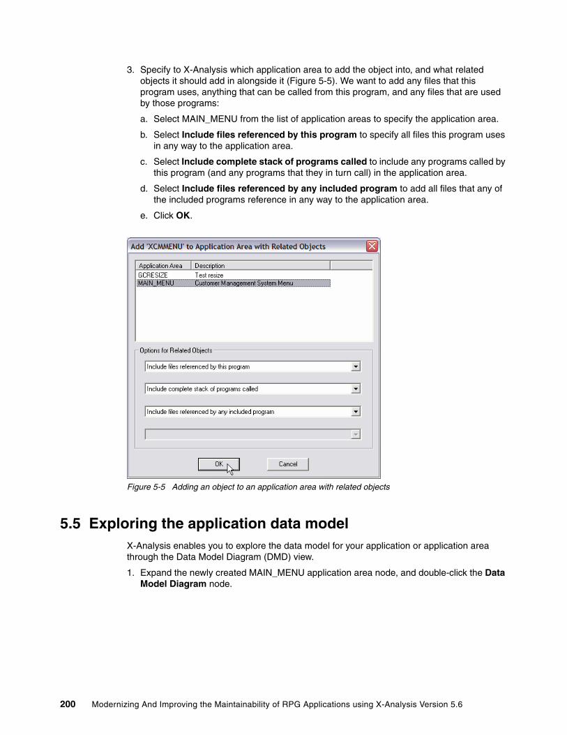
3. Specify to X-Analysis which application area to add the object into, and what related objects it should add in alongside it (Figure 5-5). We want to add any files that this program uses, anything that can be called from this program, and any files that are used by those programs:
a. Select MAIN_MENU from the list of application areas to specify the application area.
b. Select Include files referenced by this program to specify all files this program uses in any way to the application area.
c. Select Include complete stack of programs called to include any programs called by this program (and any programs that they in turn call) in the application area.
d. Select Include files referenced by any included program to add all files that any of the included programs reference in any way to the application area.
e. Click OK.
Figure 5-5 Adding an object to an application area with related objects
5.5 Exploring the application data modelX-Analysis enables you to explore the data model for your application or application area through the Data Model Diagram (DMD) view.
1. Expand the newly created MAIN_MENU application area node, and double-click the Data Model Diagram node.
200 Modernizing And Improving the Maintainability of RPG Applications using X-Analysis Version 5.6

2. This brings up the Data Modelling Diagram dialog (Figure 5-6). This dialog enables you to filter the objects that are displayed in the diagram and force X-Analysis to regenerate the diagram data. As you open the dialog from the application area’s node, the application area defaults to MAIN_MENU. Click OK to accept the defaults.
Figure 5-6 Data Modelling Diagram dialog
3. The DMD for the MAIN_MENU application area is displayed (Figure 5-7). By default X-Analysis shows all of the relationships between tables.
Figure 5-7 The data modelling diagram for an application area
Chapter 5. Recovering application design 201

Three types of relationships are presented in the X-Analysis data model:
Owns Describes a direct parent-child relationship. The primary key of the parent file forms the first part of the primary key of the child.
Refers To Describes a foreign key relationship. Fields on the dependent file can be used as the primary key to the owning file. In this scenario it is not possible to access a record from the dependent file from the owning file.
Accesses Is a stronger form of the Refers To relationship. There is an access path over the dependent file that can be accessed by the foreign key.
And three types of files are presented in the X-Analysis data model:
Internal Files located inside the application area.
External Files located outside the application area.
Interface Is an interface to a completely different application or system.
4. You can choose to view relationships with tables outside of the current application area in your DMD. To do this, select Display External Relationships in the Data Modelling Diagram dialog (Figure 5-6 on page 201) when generating the DMD. The tables external to the current application area are displayed in blue in the DMD (Figure 5-8).
Figure 5-8 Data modelling diagram including external relationships
202 Modernizing And Improving the Maintainability of RPG Applications using X-Analysis Version 5.6

5. The DMD is an interactive diagram that enables you to explore the application data model. To view the relationships for a single table rather than the entire model, you simply click on that table. Click on the table CUTMST in the diagram (see Figure 5-9).
Figure 5-9 Data modelling diagram showing relationships to a single table
6. On each relationship link is a small button. This enables you to display the fields that are involved in that relationship (Figure 5-10). Click the button on the CUSF relationship to CUTMST to view the details of the connection between these two tables.
Figure 5-10 File connection details dialog
Tip: A relationship link is the line between two tables. The button is at the end of this line where it meets the child table.
Chapter 5. Recovering application design 203

7. You can view all of the information for a single table by drilling down into the detailed DMD view. Double-click the CUTMST table to view its detailed DMD (Figure 5-11).
Figure 5-11 Detailed data modelling diagram view (Note: the navigation panel has been minimized)
204 Modernizing And Improving the Maintainability of RPG Applications using X-Analysis Version 5.6

8. Click any table in the detailed DMD view to display only the relationship between that table and the primary table in the diagram. Click the table CUTSLM to show the relationship with CUTMST(Figure 5-12). You can see that CUTMST owns (is a parent of) the file CUTSLM.
Figure 5-12 Detailed data modelling diagram showing relationship to a single table
5.5.1 Adjusting the generated data modelIn certain scenarios it is possible that the information in the data model requires some manual adjustment. This can occur if:
� The data model is not built with the appropriate parameters for your site or for a subset of your application.
� The application logic does not enable the modelling process to determine the information automatically.
In this situation you can manually adjust the data model by adding overrides. You can add or delete relationships, including complex relationships between fields that do not necessarily have the same data type.
Chapter 5. Recovering application design 205

An example of a need for an override exists in the CMS system. The Sites file CUSF should have a relationship with the Salespersons file SLMEN. The field SINIT on CUSF should logically join to the PERSON field on SLMEN. However, the CMS application is incomplete and does not contain the program logic to enable X-Analysis to determine this relationship automatically. Therefore, we manually adjust the data model to add this relationship by taking the following steps:
1. Ensure that the application library is set to allow interactive update. This is controlled by the data area XINTUPD in the application library on the iSeries server. To allow interactive update, you must set the value of this to *YES.
2. Open the application area node in the X-Analysis client navigation pane. In this example, the application library is XRAPPSSB.
3. Expand the MAIN_MENU application area node created previously. This contains a subset of the application, and the diagrams are simpler to work with.
4. Double-click Data Model Diagram.
5. Click OK in the Data Modelling Diagram dialog.
6. Double-click the CUSF file in the diagram to view its detailed DMD.
7. If interactive update was enabled correctly, the panel in Figure 5-13 will be displayed at the bottom of the DMD.
Figure 5-13 Interactive update panel
8. To add the relationship to SLMEN in this panel:
a. Select SLMEN in the Refers list.
b. Select SINIT in the By list.
c. Click Apply Changes.
The detailed DMD is updated and the relationship with SLMEN appears (Figure 5-14 on page 207).
Tip: You may need to resize the frames in the detailed DMD to see this panel. If it is not visible, drag the horizontal divide upwards to make the bottom section bigger.
206 Modernizing And Improving the Maintainability of RPG Applications using X-Analysis Version 5.6

Figure 5-14 Detailed DMD for CUSF with added relationship to SLMEN
The override that you have added stays in place even when the data model is rebuilt. This facility enables you to perfect the data model that X-Analysis built.
Chapter 5. Recovering application design 207
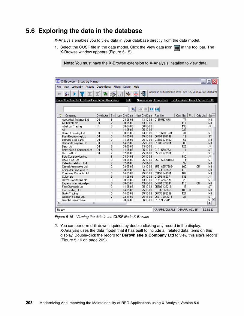
5.6 Exploring the data in the databaseX-Analysis enables you to view data in your database directly from the data model.
1. Select the CUSF file in the data model. Click the View data icon in the tool bar. The X-Browse window appears (Figure 5-15).
Figure 5-15 Viewing the data in the CUSF file in X-Browse
2. You can perform drill-down inquiries by double-clicking any record in the display. X-Analysis uses the data model that it has built to include all related data items on this display. Double-click the record for Bertwhistle & Company Ltd to view this site’s record (Figure 5-16 on page 209).
Note: You must have the X-Browse extension to X-Analysis installed to view data.
208 Modernizing And Improving the Maintainability of RPG Applications using X-Analysis Version 5.6

3. Notice that the value in the Distributor field is displayed both as the value held on the table and the name of the distributor as held on the DISTS file. X-Analysis identifies the relationship between this field and the primary key of the DISTS file. It also identifies a descriptor field for the DISTS file. This field describes the information held in the record (for example, a name or description field). It uses the foreign key value to retrieve the descriptor field from that file.
To view the possible descriptor field values, click the less-than sign (<) by the Distributor field.
Figure 5-16 Viewing a record in X-Browse
Chapter 5. Recovering application design 209

4. Select the record with the code DT and click Display (Figure 5-17).
Figure 5-17 Descriptor fields for the Distributors table
5. You see the record displayed in a new X-Browse window. You can also view the related records on dependent tables. In the X-Browse window for the Sites (CUSF) file, click View → Dependent Functions.
6. A series of tabs appears (Figure 5-18). Open the Purchases tab.
Figure 5-18 Viewing dependent record data
The data from the dependent files is displayed, but only data that is related to the record in the main display. In this case you can display all purchase records for Bertwhistle & Company Ltd. Double-click this record to drill down into the purchase record and display it in the X-Browse window.
210 Modernizing And Improving the Maintainability of RPG Applications using X-Analysis Version 5.6

5.7 Measuring referential integrityReferential integrity may not be enforced at the database level. This may be by design or due to the application pre-dating referential integrity features in the database. X-Analysis can produce an exception report by applying the reverse-engineered rules to the data in the database.
The command to run this report is XVERIFY (Figure 5-19).
Figure 5-19 The XVERIFY command
Table 5-1 XVERIFY command parameters
Data Integrity Verification (XVERIFY) Type choices, press Enter. X-Rev function library . . . . . Name Database library name . . . . . *LOADLIB Name, *LOADLIB, *LIBL X-Analysis application area . . *ALL Name, *ALL Run mode . . . . . . . . . . . . *REPORT *REPORT, *UPDATE, *PREUPDATE Maximum Errors Allowed . . . . . 5 1-999, *NOMAX, *NONE Maximum Records to Search . . . *ALL 1-999999999, *ALL, *NONE
Bottom F3=Exit F4=Prompt F5=Refresh F12=Cancel F13=How to use this display F24=More keys
Parameter Special values Description
X-Rev function library (FUNLIB)
The library that contains the data model
Database library name (DBLIB)
*LOADLIB: Use the database library that files were located in when the database was modelled. *LIBL: Use the current library list to locate files.
The library that contains the database to report over
X-Analysis application area (XA4AREA)
*ALL: Report over the complete data model.
Enables the report to be restricted to one application area
Run mode (MODE) *REPORT: Prints a report showing referential integrity failures (see below).*UPDATE: Updates the database model to downgrade or delete the relationship between files if more errors are found than the number specified in the MAXRECS parameter.*PREUPDATE: Reports on the changes that would be made in *UPDATE mode without actually making those changes
Governs what mode X-Verify runs in (see special values)
Chapter 5. Recovering application design 211

Use this command to determine how clean your production data is and to fine-tune the data model that X-Analysis generates. The report contains details of each relationship that the command verifies. It tells whether the data was verified successfully; if not, it tells you the key to the record on the parent table that is invalid and the key that cannot be found on the child.
If there are a large number of failures for a relationship then the relationship may be incorrect. Running the command with MODE(*UPDATE) can automatically do some of this fine-tuning for you. If a greater number of errors occurs than you specify on the MAXRECS parameter, then the relationship will be downgraded to a Refers To relationship. If it is already a Refers To relationship then it will be deleted from the model.
5.8 Recovering application design structureIn order to understand the existing application, it is vital to understand the function of the various programs within it and the way they interrelate. X-Analysis provides a means of graphically displaying an overview of an application or application area to help you gain this understanding. The Overview Structure Chart (OSC) shows you the hierarchy of programs in the application or application area. Entry points to the application are displayed at the top of the hierarchy - these are the top-level programs that are not called from any other program in the application or application area. Each program is colored to indicate its general function. To view the OSC for the MAIN_MENU application area, take the following steps:
1. Expand the MAIN_MENU node in the navigation pane and double-click Overview Structure Chart.
Maximum Errors Allowed (MAXRECS)
*NONE: No errors are allowed.*NOMAX: There is no maximum number of errors allowed
If MODE is *REPORT, this specifies the maximum number of entries that will appear on the report.If MODE is *UPDATE, this specifies the threshold number of errors that are allowed before a relationship will be downgraded or deleted.
Maximum Records to Search (MAXDBRECS)
*ALL: All records will be examined.*NONE: No records will be examined.
Specifies the maximum number of records in each file that will be examined.
X-Analysis library (XA4LIB) If an application area is specified, the X-Analysis library containing the application area is required.
Parameter Special values Description
212 Modernizing And Improving the Maintainability of RPG Applications using X-Analysis Version 5.6
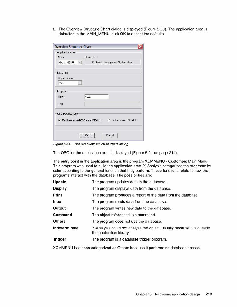
2. The Overview Structure Chart dialog is displayed (Figure 5-20). The application area is defaulted to the MAIN_MENU, click OK to accept the defaults.
Figure 5-20 The overview structure chart dialog
The OSC for the application area is displayed (Figure 5-21 on page 214).
The entry point in the application area is the program XCMMENU - Customers Main Menu. This program was used to build the application area. X-Analysis categorizes the programs by color according to the general function that they perform. These functions relate to how the programs interact with the database. The possibilities are:
Update The program updates data in the database.
Display The program displays data from the database.
Print The program produces a report of the data from the database.
Input The program reads data from the database.
Output The program writes new data to the database.
Command The object referenced is a command.
Others The program does not use the database.
Indeterminate X-Analysis could not analyze the object, usually because it is outside the application library.
Trigger The program is a database trigger program.
XCMMENU has been categorized as Others because it performs no database access.
Chapter 5. Recovering application design 213

Figure 5-21 The overview structure chart
The box in the top-right corner of each program rectangle describes the rolled up function of the program. Each type of function has a place in a hierarchy according to the strength of its interaction with the database. This box represents the strongest function that is in the stack of programs called. For example, in Figure 5-21, XCMMENU has a red update box because update functions are in the stack of programs that it calls.
You can use the OSC diagram to drill down and analyze the individual programs using the tools described starting in 4.3, “Application analysis and documentation” on page 124. These tools can help complete your understanding of the application.
5.9 Recovering business rulesSome of the most valuable artifacts in your existing applications are the business rules that are coded into them. Very often these applications were not developed in a modular fashion; the programs perform multiple functions such as database access, screen handling, application workflow, or business logic. If business logic is embedded in a screen program it cannot be accessed by any other programs. If the same business rules should be applied elsewhere, they have to be duplicated, which increases the maintenance overhead if the logic has to change in the future.
One goal when designing a component-based architecture is for each component in a system to perform one clearly defined task. To move an existing application toward this kind of
214 Modernizing And Improving the Maintainability of RPG Applications using X-Analysis Version 5.6
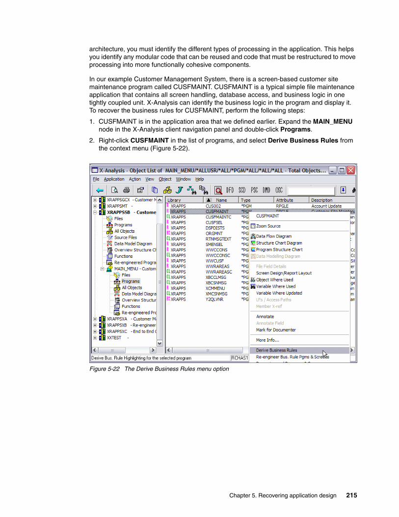
architecture, you must identify the different types of processing in the application. This helps you identify any modular code that can be reused and code that must be restructured to move processing into more functionally cohesive components.
In our example Customer Management System, there is a screen-based customer site maintenance program called CUSFMAINT. CUSFMAINT is a typical simple file maintenance application that contains all screen handling, database access, and business logic in one tightly coupled unit. X-Analysis can identify the business logic in the program and display it. To recover the business rules for CUSFMAINT, perform the following steps:
1. CUSFMAINT is in the application area that we defined earlier. Expand the MAIN_MENU node in the X-Analysis client navigation panel and double-click Programs.
2. Right-click CUSFMAINT in the list of programs, and select Derive Business Rules from the context menu (Figure 5-22).
Figure 5-22 The Derive Business Rules menu option
Chapter 5. Recovering application design 215
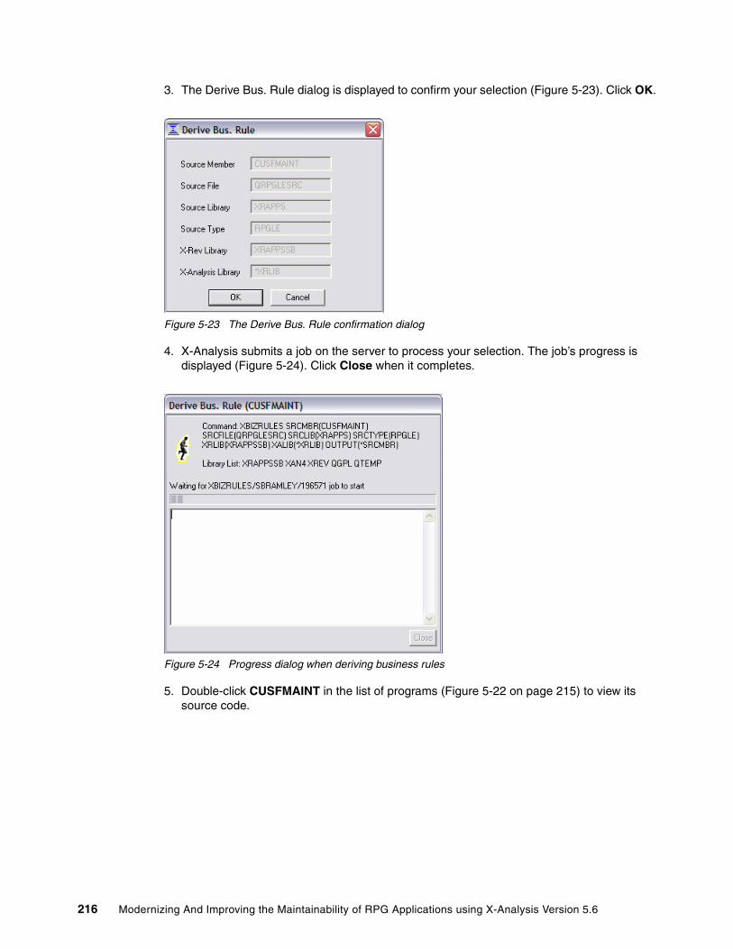
3. The Derive Bus. Rule dialog is displayed to confirm your selection (Figure 5-23). Click OK.
Figure 5-23 The Derive Bus. Rule confirmation dialog
4. X-Analysis submits a job on the server to process your selection. The job’s progress is displayed (Figure 5-24). Click Close when it completes.
Figure 5-24 Progress dialog when deriving business rules
5. Double-click CUSFMAINT in the list of programs (Figure 5-22 on page 215) to view its source code.
216 Modernizing And Improving the Maintainability of RPG Applications using X-Analysis Version 5.6

6. X-Analysis shows the complete source of the program by default. To view the business rules that it derives (Figure 5-25), select View → Business Rules Code.
Figure 5-25 Business rules view for CUSFMAINT
Chapter 5. Recovering application design 217

7. X-Analysis can display these business rules as pseudo code (Figure 5-26). Select View → Business Rules Pseudo Code.
Figure 5-26 Business Rules Pseudo Code view of CUSFMAINT
In addition to deriving the business rules behind the screen validation in this program, X-Analysis relates the business rule back to the application data model. In Figure 5-26, the rule for validating a customer’s telephone number is applied to the TELNO field on the CUSF file. From a logical point of view you see the identified business entity customer, which has a property of telephone number. Both the business rule for validating the telephone number and where it is physically stored and maintained in the application are now known.
Tip: To derive the business rules for an entire application or application area, right-click the node in the X-Analysis client navigation pane and select Derive Business Rules.
218 Modernizing And Improving the Maintainability of RPG Applications using X-Analysis Version 5.6

Chapter 6. Using the recovered model
This chapter describes how you can make further use of the application model that X-Analysis created. You will learn how to export the data model to other applications and how to make further use of the metadata X-Analysis has built.
6
© Copyright IBM Corp. 2006. All rights reserved. 219
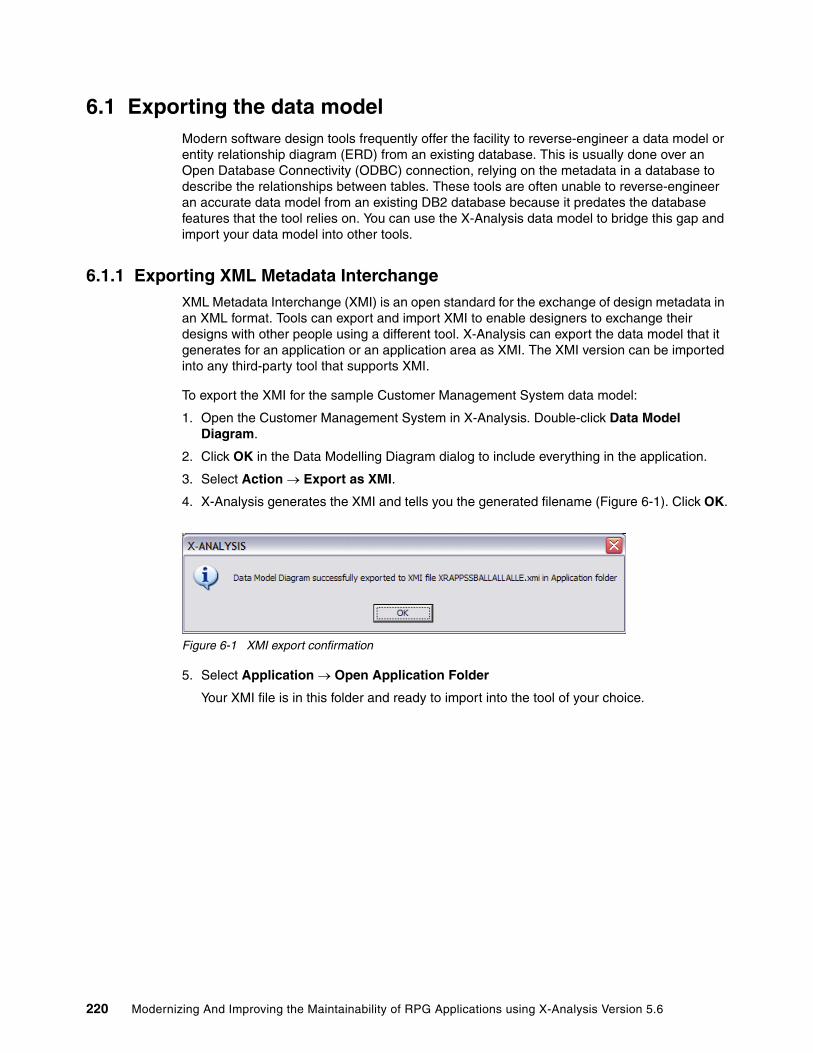
6.1 Exporting the data modelModern software design tools frequently offer the facility to reverse-engineer a data model or entity relationship diagram (ERD) from an existing database. This is usually done over an Open Database Connectivity (ODBC) connection, relying on the metadata in a database to describe the relationships between tables. These tools are often unable to reverse-engineer an accurate data model from an existing DB2 database because it predates the database features that the tool relies on. You can use the X-Analysis data model to bridge this gap and import your data model into other tools.
6.1.1 Exporting XML Metadata InterchangeXML Metadata Interchange (XMI) is an open standard for the exchange of design metadata in an XML format. Tools can export and import XMI to enable designers to exchange their designs with other people using a different tool. X-Analysis can export the data model that it generates for an application or an application area as XMI. The XMI version can be imported into any third-party tool that supports XMI.
To export the XMI for the sample Customer Management System data model:
1. Open the Customer Management System in X-Analysis. Double-click Data Model Diagram.
2. Click OK in the Data Modelling Diagram dialog to include everything in the application.
3. Select Action → Export as XMI.
4. X-Analysis generates the XMI and tells you the generated filename (Figure 6-1). Click OK.
Figure 6-1 XMI export confirmation
5. Select Application → Open Application Folder
Your XMI file is in this folder and ready to import into the tool of your choice.
220 Modernizing And Improving the Maintainability of RPG Applications using X-Analysis Version 5.6
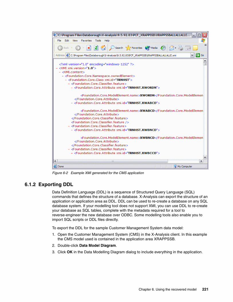
Figure 6-2 Example XMI generated for the CMS application
6.1.2 Exporting DDLData Definition Language (DDL) is a sequence of Structured Query Language (SQL) commands that defines the structure of a database. X-Analysis can export the structure of an application or application area as DDL. DDL can be used to re-create a database on any SQL database system. If your modelling tool does not support XMI, you can use DDL to re-create your database as SQL tables, complete with the metadata required for a tool to reverse-engineer the new database over ODBC. Some modelling tools also enable you to import SQL scripts or DDL files directly.
To export the DDL for the sample Customer Management System data model:
1. Open the Customer Management System (CMS) in the X-Analysis client. In this example the CMS model used is contained in the application area XRAPPSSB.
2. Double-click Data Model Diagram.
3. Click OK in the Data Modelling Diagram dialog to include everything in the application.
Chapter 6. Using the recovered model 221
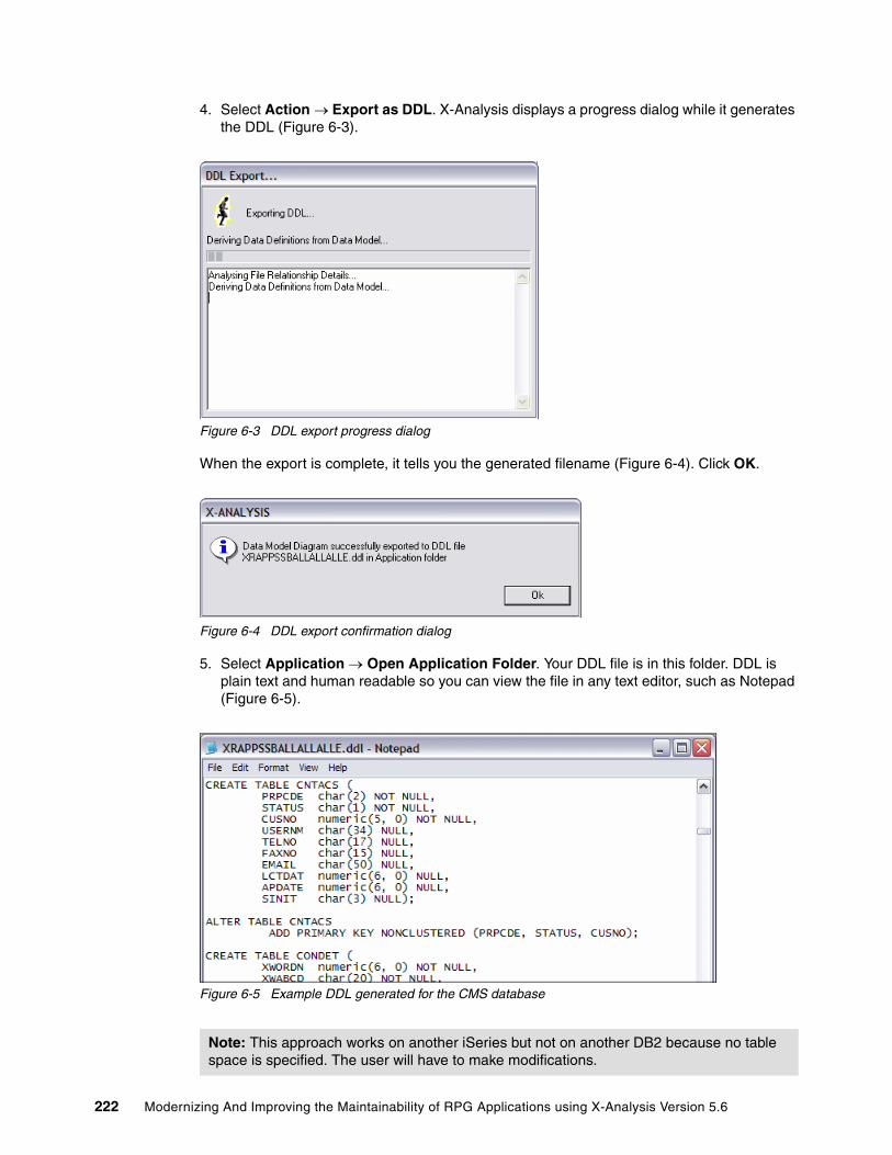
4. Select Action → Export as DDL. X-Analysis displays a progress dialog while it generates the DDL (Figure 6-3).
Figure 6-3 DDL export progress dialog
When the export is complete, it tells you the generated filename (Figure 6-4). Click OK.
Figure 6-4 DDL export confirmation dialog
5. Select Application → Open Application Folder. Your DDL file is in this folder. DDL is plain text and human readable so you can view the file in any text editor, such as Notepad (Figure 6-5).
Figure 6-5 Example DDL generated for the CMS database
Note: This approach works on another iSeries but not on another DB2 because no table space is specified. The user will have to make modifications.
222 Modernizing And Improving the Maintainability of RPG Applications using X-Analysis Version 5.6

6.1.3 Exporting to Microsoft VisioX-Analysis generates Microsoft Visio drawings for any X-Analysis data model diagram. You can share these drawings with other Visio users or you can incorporate them into your documentation if you have Microsoft Visio installed on your PC.
To export the data model diagram for the sample Customer Management System data model to Visio:
1. Open the Customer Management System in X-Analysis. Double-click Data Model Diagram.
2. Click OK in the Data Modelling Diagram dialog to include everything in the application.
3. Select Action → Export to MS Visio.
X-Analysis generates a new Visio entity relationship diagram (Figure 6-6). Depending on your security settings, Visio may prompt you to enable macros during this process
Figure 6-6 CMS data modelling diagram exported into Microsoft Visio
6.2 Using the X-Analysis databaseThe metadata database that underlies X-Analysis is a valuable resource, and it contains information that can be leveraged for your own purposes. In this section we examine the structure of the database and show some examples of how you might use the information that it contains.
Chapter 6. Using the recovered model 223

6.2.1 The data model databaseThe X-Analysis data modelling process generates five core tables (Table 6-1).
Table 6-1 Tables generated by the X-Analysis data modelling process
Figure 6-7 depicts the relationship between the tables.
Figure 6-7 The X-Analysis data model database
Table XPIDSEach physical file in the application has a record in the XPIDS table.
Table 6-2 XPIDS file layout
Name Description
XPIDS Primary identifiers
XDD Data dictionary
XRELS Relationships
XSHKEYS Relationship detail
XKEYMAP Access paths
Field Datatype Length Description
PIDPF CHAR 10 The name of the physical file.
PIDLF CHAR 10 The name of the access path containing the primary key.
TEXT CHAR 50 The description of the access path file (DDS text or SQL label).
NORMLF CHAR 10 This is a reserved field.
PIDNUM CHAR 1 Yes or No flag indicating whether the file has an automatically incremented sequential key.
KEYnn CHAR 10 The key fields to the file in order. The model supports up to 10 key fields in a file key. The field names are as they appear in the physical file.
ALWDSP CHAR 1 Governs whether a display record function is allowed.
ALWUPD CHAR 1 Governs whether an update record function is allowed.
ALWDEL CHAR 1 Governs whether a delete record function is allowed.
PFLVID CHAR 13 The record format level identifier of the version of the file that this record describes.
224 Modernizing And Improving the Maintainability of RPG Applications using X-Analysis Version 5.6
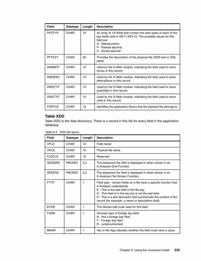
Table XDDTable XDD is the data dictionary. There is a record in this file for every field in the application database.
Table 6-3 XDD file layout
PFDTYP CHAR 10 An array of 1A fields that contain the data types of each of the key fields held in KEY1-KEY10. The possible values for this field are:A - AlphanumericP - Packed decimalS - Zoned decimal
PFTEXT CHAR 50 Provides the description of the physical file (DDS text or SQL label).
XWAMTF CHAR 10 Used by the X-Web module, indicating the field used to store prices in this record.
XWDESC CHAR 10 Used by the X-Web module, indicating the field used to store descriptions in this record.
XWQTYF CHAR 10 Used by the X-Web module, indicating the field used to store quantities in this record.
XWUTYF CHAR 10 Used by the X-Web module, indicating the field used to store units in this record.
PDPFLB CHAR 10 Identifies the application library that the physical file belongs to.
Field Datatype Length Description
VFLD CHAR 10 Field name
VFILE CHAR 10 Physical file name
FLDCLS CHAR 10 Reserved
SEQGRD PACKED 5,2 The sequence the field is displayed in when shown in an X-Analysis Grid Function.
SEQFSC PACKED 5,2 The sequence the field is displayed in when shown in an X-Analysis Flat Screen Function.
FTYP CHAR 1 Field type - certain fields on a file have a specific function that X-Analysis understands:K - This is the last field in the file key.H - This field is in the key but is not the last field.D - This is a text descriptor that summarizes the content of the record (for example, a name or description field).
ECDE CHAR 1 The iSeries edit code used for this field.
FGNK CHAR 1 Denotes type of foreign key field:N - Not a foreign key fieldF - Foreign key fieldR - (undocumented)
BNAW CHAR 1 Yes or No flag indicates whether the field must have a value.
Field Datatype Length Description
Chapter 6. Using the recovered model 225

CDFD CHAR 1 Yes or No flag to indicate whether there are records on the XCODES file for this field. XCODES contain a list of allowable values for the field.
YNFD CHAR 1 Yes or No flag to indicate whether this is a Yes or No field. If Yes (Y), only the values “Y” or “N” may be entered into the field.
DATP CHAR 1 If identified as a date or time field, this field indicates the type of date:Z - TimestampT - TimeD - Date6 - Six-digit date7 - Seven-digit date8 - Eight-digit date
DATF CHAR 10 If identified as a date or time field, this indicates the format of the date. This may be a standard format (for example *ISO) or a descriptive format (for example, CCYYMMDD).
VPGM CHAR 10 The name of an external validation program that can be called to validate the field content.
VPRM CHAR 1 Indicates whether only the field itself or the entire database record is passed to the validation program held in VPGM.
VCHK CHAR 1 Indicates whether the validation program is called when the field is blank.
XVAL CHAR 1 Reserved
WPTYP CHAR 2 (undocumented)
GATTR CHAR 1 The typical display characteristics of the field: H - Hidden (it is never displayed on screen)O - Output onlyB - Both input and outputP - The field cannot be used by an application
WHCHD1 CHAR 20 Reserved
WHCHD2 CHAR 20 Reserved
WHCHD3 CHAR 20 Reserved
FLDHDG CHAR 50 The column heading for the field
FDATTR CHAR 1 Data type:A - AlphanumericP - Packed decimalS - Zoned decimal
FLDLEN CHAR 3 Field length in bytes
FLDDEC CHAR 2 Decimal precision
FLDBFP CHAR 5 The position of the field in the record buffer.
FLDDLN CHAR 3 Used by X-Web to control what length of the field is displayed.
FMGRP CHAR 1 Used to control grouping of fields in displays.
Field Datatype Length Description
226 Modernizing And Improving the Maintainability of RPG Applications using X-Analysis Version 5.6

Table XRELSThe XRELS table details the relationships between tables in the data model.
Table 6-4 XRELS file layout
Table XSHKEYSThe XSHKEYS table is the child of the file XRELS and describes the fields involved in the relationships that it holds.
Table 6-5 XSHKEYS file layout
Field Datatype Length Description
OWNPF CHAR 10 The physical file that is the parent in the relationship.
OWNTXT CHAR 50 The text associated with the parent file.
DEPPF CHAR 10 The physical file that is the child in the relationship.
DEPSEQ PACKED 5,2 Used to order the child relationships that the parent file has.
DEPTXT CHAR 50 The text associated with the child file.
DEPLF CHAR 10 The access path that is used to retrieve records from the child file. This will be the access path that is sequenced by the foreign key fields in the relationship.
RFONLY CHAR 1 Describes the type of relationship: Y - There is no access path over the child file sequenced by the foreign key (Refers To).O - The access path held in DEPLF is the primary access path for the child (as specified in the field PIDLF on the file XPIDS) (Owns).Blank - The access path held in DEPLF is not the primary access path for the child (Accesses).
ORIGIN CHAR 1 Reserved
OWNLF CHAR 10 Reserved
RELID PACKED 7,0 This is a unique identifier for this relationship.
R1T1 CHAR 1 Flag indicating a one-to-one rather than a one-to-many relationship.
RELPTY CHAR 1 Used to sequence referential integrity tests.
Field Datatype Length Description
FILE CHAR 10 The child file
MFILE CHAR 10 The parent file
KSEQ PACKED 5,2 The sequence of the fields in the key
FLD CHAR 10 Field on the child file
MFLD CHAR 10 Field on the parent file
CONST CHAR 20 A constant value used to join the files
RELID PACKED 7,0 The unique identifier for the relationship as held on XRELS
Chapter 6. Using the recovered model 227

XKEYMAPThe XKEYMAP table details all of the access paths over each physical file in the data model.
Table 6-6 XKEYMAP file layout
6.2.2 Using X-Browse to explore the data model databaseThe easiest way to view the data in the data model is to use the data dictionary facility provided within X-Analysis:
1. Open the Customer Management System in X-Analysis.
2. Click the data dictionary icon in the tool bar. An X-Browse window opens showing the data in the file XPIDS.
For more information about using X-Browse, review 5.6, “Exploring the data in the database” on page 208.
Field Datatype Length Description
KMFILE CHAR 10 The physical file that the access path is over.
KMLF CHAR 10 The file containing the access path. (This may be the physical itself if it is keyed.)
KMKFLD CHAR 200 An array of 10A elements holding the field names of the key fields. The field names are sequenced as they appear in the key.
KMRFLD CHAR 200 Reserved
KMFAT1 CHAR 200 Reserved
KMFAT2 CHAR 200 Reserved
KMPFUN CHAR 1 A flag indicating a physical file with a unique key.
KMSUPR CHAR 10 Reserved
KM#OWN ZONED 2,0 Reserved
KMLFTX CHAR 50 Text associated with the logical file.
KMLFSQ PACKED 5,0 Dictates the sequence the logical files over this physical file are displayed in.
KMLFKS CHAR 1 Reserved
KMDKIX CHAR 20 An array of 1A elements holding the data types of the fields in the key:A - AlphanumericP - Packed decimalS - Zoned decimal
KMSELO CHAR 1 Flag indicating whether the file has select/omit criteria specified.
KMFSEL CHAR 1 Flag indicating whether the logical file renames fields from the physical file.
KMLFLB CHAR 10 The library that the logical file resides in.
228 Modernizing And Improving the Maintainability of RPG Applications using X-Analysis Version 5.6

6.3 Using the business rules databaseThe X-Analysis business rules extraction process builds metadata about your RPG applications in order to identify the business rules code. You can write your own programs and queries to use this metadata. For example, you may have code that has been copied between programs over a period of years. To improve the maintainability of this code, externalize the code from these programs. The problem that this poses is locating where the copied code has been used. Workfield names are likely to differ between programs. The code may have mutated slightly to fit developers’ individual coding styles. It may have been adjusted to fit with the style of new releases of the RPG language. Simple string searches are therefore unlikely to be a good way of identifying where the code has been replicated. You could manually search through source code but this would be a painful and time-consuming process. The business rules database can be used in conjunction with X-Analysis to mitigate the effort.
The business rules extraction process builds information in several layers. Each layer uses information gathered in the previous step. At each level the data becomes more directly related to business rules. The levels are:
� Level 1: Contains raw information about source code in individual programs.� Level 2: Identifies the logical purpose of some of the programs and fields in the system.� Level 3: Identifies the purpose of blocks of code within a program.
6.3.1 Level 1Tables at level 1 contain raw information about source code in individual programs:
XERRIND Holds indicators used as error message indicators in a program.XEXFLDCMPS Contains valid comparisons for fields specified in programs.XEXFLDRNGS Contains valid ranges of values for fields specified in programs.XEXFLDTRKR Tracks the movement of data between fields in programs.XEXFLDVALS Details the permitted values for a field in a program.XEXPGMBLKS Describes code block structures in a program and how they are nested.XEXPGMFLDS Stores the fields that have been defined in the program.XEXPGMLSTS Holds details of the list structures.XEXPGMMGSS Details the program statements where messages are referenced.XEXPGMSTTS Holds generic statement types as they occur in a program.XEXPGMCTAS Holds details of the compile time array defined in a program.
Table XERRINDTable XERRIND holds indicators used as error message indicators within programs. Each indicator definition has two records on this file. The first record has the indicator listed by number in the indicator field. The second record sets the position for this indicator in the indicator array field to 1.
Table 6-7 XERRIND file layout
Field Datatype Length Description
XEPGM CHAR 10 Program
XEIND CHAR 2 Indicator
XEFLD CHAR 30 Field
XEFILE CHAR 10 The device file where the indicator is used
XEFMT CHAR 10 The record format that the indicator is defined on
Chapter 6. Using the recovered model 229
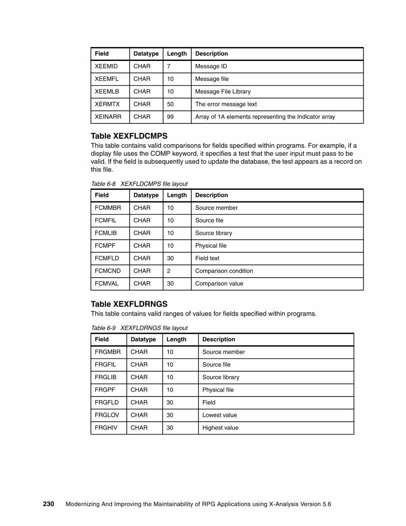
Table XEXFLDCMPSThis table contains valid comparisons for fields specified within programs. For example, if a display file uses the COMP keyword, it specifies a test that the user input must pass to be valid. If the field is subsequently used to update the database, the test appears as a record on this file.
Table 6-8 XEXFLDCMPS file layout
Table XEXFLDRNGSThis table contains valid ranges of values for fields specified within programs.
Table 6-9 XEXFLDRNGS file layout
XEEMID CHAR 7 Message ID
XEEMFL CHAR 10 Message file
XEEMLB CHAR 10 Message File Library
XERMTX CHAR 50 The error message text
XEINARR CHAR 99 Array of 1A elements representing the Indicator array
Field Datatype Length Description
FCMMBR CHAR 10 Source member
FCMFIL CHAR 10 Source file
FCMLIB CHAR 10 Source library
FCMPF CHAR 10 Physical file
FCMFLD CHAR 30 Field text
FCMCND CHAR 2 Comparison condition
FCMVAL CHAR 30 Comparison value
Field Datatype Length Description
FRGMBR CHAR 10 Source member
FRGFIL CHAR 10 Source file
FRGLIB CHAR 10 Source library
FRGPF CHAR 10 Physical file
FRGFLD CHAR 30 Field
FRGLOV CHAR 30 Lowest value
FRGHIV CHAR 30 Highest value
Field Datatype Length Description
230 Modernizing And Improving the Maintainability of RPG Applications using X-Analysis Version 5.6

Table XEXFLDTRKRThis table tracks the movement of data between fields in programs.
Table 6-10 XEXFLDTRKR file layout
Table XEXFLDVALSThis table details the permitted values for a field in a program. There is one record on this file for each permitted value. For example, if a display file uses the VALUES keyword it restricts the values that the user can enter for a field. If the field is subsequently used to populate a field on the database, then the database field has a record on this file for each value specified on the VALUES keyword.
Table 6-11 XEXFLDVALS file layout
Table XEXPGMBLKSThis table describes the code block structures within a program and how they are nested.
Table 6-12 XEXPGMBLKS file layout
Field Datatype Length Description
TRKMBR CHAR 10 Source member
TRKFIL CHAR 10 Source file
TRKLIB CHAR 10 Source library
TRKRRN ZONED 5,0 Relative record number (RRN) of the source instruction
TRKFRF CHAR 30 From field
TRKTOF CHAR 30 To field
TRKDIR CHAR 1 Direction - which field is the data moving from: F - The data is being moved from the from field (TRKFRF) into the to field (TRKTOF).T - The data is being moved from the to field (TRKTOF) into the from field (TRKFRF).
Field Datatype Length Description
FVLMBR CHAR 10 Source member
FVLFIL CHAR 10 Source file
FVLLIB CHAR 10 Source library
FVLPF CHAR 10 Physical file
FVLFLD CHAR 30 Field
FVLVAL CHAR 30 Permitted field value
Field Datatype Length Description
BLKMBR CHAR 10 Source member
BLKFIL CHAR 10 Source file
BLKRRN ZONED 5,0 The relative record number (RRN) of the source statement where the block operation occurs
Chapter 6. Using the recovered model 231

Table XEXPGMFLDSThis table stores the fields defined in a program.
Table 6-13 XEXPGMFLDS file layout
BLKBXE CHAR 1 Type of block operation:B - Begin (example is IF)X - Extend (example is ELSE)E - End (example is ENDIF)
BLKLVL ZONED 3,0 Nesting level
BLKTYP CHAR 10 RPG operation code
Field Datatype Length Description
FLDMBR CHAR 10 Source member
FLDFIL CHAR 10 Source file
FLDLIB CHAR 10 Source library
FLDFLD CHAR 30 Field
FLDTYP CHAR 1 Field type
FLDLEN ZONED 3,0 Field length
FLDDEC CHAR 2 Field decimal places
FLDDYN CHAR 1 Date field (Y/N)
FLDORI CHAR 1 Field origin:W- WorkfieldD - Database
FLDDFL CHAR 10 If the field is linked to a database field, specifies the field name.
FLDDRF CHAR 10 Name of renamed record format
FLDDBF CHAR 30 Name of the field as defined on the database
FLDLKF CHAR 30 Like field
FLDLKS CHAR 1 Like field adjusted sign
FLDLKV ZONED 2,0 Like field adjusted value
FLDTRK CHAR 30 If the field is linked to a tracked database field, what the field name is.
FLDDVF CHAR 10 The device file that the field is defined on.
FLDDFF CHAR 10 The record format in the device file that the field is defined on.
FLDSTR CHAR 30 The name of the data structure that contains the field.
FLDDTF CHAR 1 Date format
Field Datatype Length Description
232 Modernizing And Improving the Maintainability of RPG Applications using X-Analysis Version 5.6

Table XEXPGMLSTSXEXPGMLSTS holds details of the list structures (key lists and parameter lists) defined in a program. There will be one record for each field in the list.
Table 6-14 XEXPGMLSTS file layout
Table XEXPGMMGSSXEXPGMMGSS details the program statements where messages are referenced.
Table 6-15 XEXPGMMGSS file layout
Field Datatype Length Description
LSTMBR CHAR 10 Source member
LSTFIL CHAR 10 Source file
LSTLIB CHAR 10 Source library
LSTRRN ZONED 5,0 RRN of the source statement where the list is defined
LSTTYP CHAR 1 List type:K - Key listP - Parameter list
LSTLST CHAR 20 List name. If this is defined in line (for example a prototyped call or by using PARM statements after the CALL operation), this is generated.
LSTSEQ ZONED 3,0 The sequence of the field within the list
LSTFLD CHAR 30 The name of the field in the list
Field Datatype Length Description
MSGMBR CHAR 10 Source member
MSGFIL CHAR 10 Source file
MSGLIB CHAR 10 Source library
MSGRRN ZONED 5,0 RRN of the source statement where the message is referenced
MSGMID CHAR 7 Message ID
MSGMFL CHAR 10 Message file
MSGMLB CHAR 10 Message file library
MSGMTX CHAR 50 Message text
MSGEIN CHAR 2 Any program error indicator associated with the message
MSGEFD CHAR 30 The underlying database field that the error refers to
MSGEFL CHAR 10 The file that the underlying database field is on
Chapter 6. Using the recovered model 233

Table XEXPGMSTTSThis table holds the generic types of statements as they occur in a program. For example, any operations that compare variables (such as IF or WHEN) are logically grouped as the same generic type of operation.
Table 6-16 XEXPGMSTTS file layout
Table XEXPGMCTASThis table holds details of the compile time arrays that are defined in a program.
Table 6-17 XEXPGMCTAS file layout
6.3.2 Level 2The level 2 data derivation identifies the logical purpose of some of the programs and fields in a system. Level 2 contains these files:
XEXPMTFLDS Details which fields programs use as prompt fieldsXEXRTNCDES Details which fields programs uses a return codes.XEXSELPGMS Details programs other programs use to perform record selection from a list.XEXUPDFUNS Contains the physical files causing X-Analysis functions to be created.XEXVALFLGS Contains validation flags.
Table XEXPMTFLDSThis table details the fields programs use as prompt fields. Prompt fields are fields that are used to request a prompt or selection program and can be excluded from business rules.
Table 6-18 XEXPMTFLDS file layout
Field Datatype Length Description
STTMBR CHAR 10 Source member
STTFIL CHAR 10 Source file
STTLIB CHAR 10 Source library
STTRRN ZONED 5,0 Source RRN
STTTYP CHAR 10 Statement type
STTTQL CHAR 10 Type qualifier
Field Datatype Length Description
CTAMBR CHAR 10 Source member
CTAFIL CHAR 10 Source file
CTALIB CHAR 10 Source library
CTACTA CHAR 30 Compile time array name
CTARRN ZONED 5,0 RRN of the source statement where the array is located. This is the content of the array rather than the definition of the variable.
Field Datatype Length Description
PMTMBR CHAR 10 Source member
PMTFIL CHAR 10 Source file
234 Modernizing And Improving the Maintainability of RPG Applications using X-Analysis Version 5.6

Table XEXRTNCDESXEXRTNCDES details which fields programs use as return codes. This enables the identification of validation code where a program is passed values and returns a result.
Table 6-19 XEXRTNCDES file layout
Table XEXSELPGMSThis table details which programs other programs use to perform record selection from a list. These calls can be excluded from business rules.
Table 6-20 XEXSELPGMS file layout
Table XEXUPDFUNSThis table contains the physical files for which X-Analysis functions are created currently performed in this program.
Table 6-21 XEXUPDFUNS file layout
PMTLIB CHAR 10 Source library
PMTPMT CHAR 30 Prompt field
Field Datatype Length Description
RTCMBR CHAR 10 Source member
RTCFIL CHAR 10 Source file
RTCLIB CHAR 10 Source library
RTCCDE CHAR 30 Return code field
Field Datatype Length Description
SELMBR CHAR 10 Source member
SELFIL CHAR 10 Source file
SELLIB CHAR 10 Source library
SELPGM CHAR 10 Selection program
Field Datatype Length Description
UDFMBR CHAR 10 Source member
UDFFIL CHAR 10 Source file
UDFLIB CHAR 10 Source library
UDFFUN CHAR 10 Function file
UDFTYP CHAR 1 Function type
UDFMAP CHAR 20 Map name
Field Datatype Length Description
Chapter 6. Using the recovered model 235

Table XEXVALFLGSTable XEXVALFLGS identifies validation flags, which are fields set to indicate error conditions within a program. They are similar to return codes but are not used as program parameters.
Table 6-22 XEXVALFLGS file layout
6.3.3 Level 3Level 3 derivation identifies the purpose of blocks of code in a program. It contains these files:
XEXTRGLINS Identifies the trigger lines within a program.XEXOTHFILS Details all non-owner file access performed in a program.
Table XEXTRGLINSTable XEXTRGLINS contains the trigger lines. A trigger line is a line of code where a specific operation occurs within a program. The possible operations are:
� A comparison with a database field or a field linked to an underlying database field
� A comparison with a program return code
� A comparison with a program validation flag
� Comparing or setting the value of an error indicator after a subroutine is executed
� Comparing or setting the value of program parameters
� Database input or output for validation purposes
� Update of a file that is not the primary file in the program (secondary update)
� Reading a file that the program’s primary file does not have at least a refers to relationship with in the X-Analysis data model (non-owner read)
� A call to a program that does not meet any of the following criteria:
– Interactive programs
– Print programs
– Selection programs (as held on the file XEXSELPGMS)
– Excluded programs (as held on the file XEXCPGM)
� Executing a validation subroutine
� A statement that references a message (as held on XEXPGMMGSS)
� A Synon User Exit Point
� Populating a screen workfield
Field Datatype Length Description
VLFMBR CHAR 10 Source member
VLFFIL CHAR 10 Source file
VLFLIB CHAR 10 Source library
VLFFLG CHAR 30 Validation flag
236 Modernizing And Improving the Maintainability of RPG Applications using X-Analysis Version 5.6

Table 6-23 XEXTRGLINS file layout
Table XEXOTHFILSThis table holds details of all non-owner file access performed in a program.
Table 6-24 XEXOTHFILS file layout
Field Datatype Length Description
TRGMBR CHAR 10 Source member
TRGFIL CHAR 10 Source file
TRGLIB CHAR 10 Source library
TRGRRN ZONED 5,0 Source RRN
TRGTYP CHAR 1 Trigger type:V - ValidationU - Secondary updateR - Non-owner readC - Program callE - Execute validation subroutineP - Population of program parametersX - Synon user exitW - Populating a screen workfield
TRGVTP CHAR 1 If field TRGTYP = V, this contains validation type:M - Message statementF - File validation statementC - Comparison statementIf field TRGTYP = C, this contains call type:M - Message programD - Date programV - Validation programP - Print program*BLANK - Other program
TRGCTP CHAR 1 Comparison type:F - Field comparisonR - Return code comparisonV - Validation flag comparisonI - Resulting indicator comparison
Field Datatype Length Description
OTFMBR CHAR 10 Source member
OTFFIL CHAR 10 Source file
OTFLIB CHAR 10 Source library
OTFPF CHAR 10 Physical file name
OTFTYP CHAR 1 Type:R - ReadU - Update
Chapter 6. Using the recovered model 237

6.3.4 Level 4Tables at level 4 hold the extracted business rules. The tables are:
XEXEXTLGC Contains trigger lines with a valid piece of business logic.XEXBIZRLES Contains the definition of the business rules that were extracted.
Table XEXEXTLGCThis table contains information when a trigger line (XEXTRGLINS) contains a valid piece of business logic. In this case, the code block at the trigger line is written to this file.
Table 6-25 XEXTLGC file layout
Table XEXBIZRLESThis table contains the definitions of the business rules that have been extracted.
Table 6-26 XEXBIZRLES file layoutr
Field Datatype Length Description
EXTMBR CHAR 10 Source member
EXTFIL CHAR 10 Source file
EXTLIB CHAR 10 Source library
EXTRRN ZONED 5,0 The RRN of the source record
EXTTYP CHAR 1 Extract type:As TRGTYP above and additionally:S - Validation subroutineT - Validation subroutineZ - Synon user exit or XBIZRULES derived logicD - Shadow program definition specificationF - Shadow program file specification
EXTSTP CHAR 1 Extract subtype:As TTGVTYP above and additionally:L - List type definitionR - Rename type definitionS - Secondary workfield move
EXTCDE CHAR 100 Source code
EXTPF CHAR 10 The underlying physical file that the code relates to
EXTFNC CHAR 2 Function type
Field Datatype Length Description
BIZMBR CHAR 10 Source member
BIZFIL CHAR 10 Source file
BIZLIB CHAR 10 Source library
BIZRRN ZONED 5,0 RRN of the source line where the business rule occurs
238 Modernizing And Improving the Maintainability of RPG Applications using X-Analysis Version 5.6

Here is a simple example of how you can apply this information to identify business rules. This is useful when modelling the functionality in the existing system as part of a modernization exercise.
The table XEXBIZRLES contains the business rules that exist in our system. The business rules are related back to underlying fields in our database. We can query XEXBIZRLES to display all of the business rules that are applied to a particular table. To do this for the Sites table CUSF, use the SQL statement shown in Example 6-1.
Example 6-1 Querying business rules applied to the sites table
SELECT BIZMBR, BIZFIL, BIZLIB, BIZRRN, BIZTYP, BIZNUM, BIZFLD, BIZOBJ, BIZRUL FROM XRAPPSSB/XEXBIZRLES WHERE BIZOBJ = ‘CUSF’ ORDER BY BIZMBR, BIZNMUM
BIZTYP CHAR 1 Business rule type:C - Program callL - Field logicR - Non-owner file readV - ValidationU - Secondary file update
BIZNUM ZONED 5,0 Business rule number
BIZFLD CHAR 30 The underlying tracked database field that this rule relates to.
BIZOBJ CHAR 10 The file that the tracked field is on, or the program called if this rule is a program call.
BIZRUL CHAR 100 Text description of the business rule
BIZSHMBR CHAR 10 Shadow source member
BIZSHFIL CHAR 10 Shadow source file
BIZSHLIB CHAR 10 Shadow source library
BIZSHRRN ZONED 5,0 Shadow source RRN
BIZACTIVE CHAR 1 Is the business rule active? Yes or No
BIZCAT01 CHAR 10 Rule Category Number 01
BIZCAT02 CHAR 10 Rule Category Number 02
BIZCAT03 CHAR 10 Rule Category Number 03
BIZCAT04 CHAR 10 Rule Category Number 04
BIZCAT05 CHAR 10 Rule Category Number 05
BIZCAT06 CHAR 10 Rule Category Number 06
BIZCAT07 CHAR 10 Rule Category Number 07
BIZCAT08 CHAR 10 Rule Category Number 08
BIZCAT09 CHAR 10 Rule Category Number 09
BIZCAT10 CHAR 10 Rule Category Number 10
Field Datatype Length Description
Chapter 6. Using the recovered model 239

This query produces the results shown in Figure 6-8. These results show that there are various business rules that are applied to fields on the file CUSF. You see that in the sample application these business rules have been duplicated. Both CUSFMAINT and WWCUSF would have to be amended if any of the business rules relating to the customer have to change. The BIZRRN field holds the relative record number of the source line where the business rule is coded into the source member. These results help you model the business logic in the existing application more easily than reading through the source alone.
Figure 6-8 Query results from Example 6-1 on page 239
BIZMBR BIZFIL BIZLIB BIZRRN BIZTYP BIZNUM BIZFLD BIZOBJ BIZRULCUSFMAINT QRPGLESRC XRAPPS 202 V 1 CNAME CUSF You must enter the customer name.CUSFMAINT QRPGLESRC XRAPPS 211 V 2 TELNO CUSF The telephone no. is invalid.CUSFMAINT QRPGLESRC XRAPPS 223 V 3 FAXNO CUSF The fax. no. is invalid.CUSFMAINT QRPGLESRC XRAPPS 235 V 4 DSDCDE CUSF The distributor is invalid.CUSFMAINT QRPGLESRC XRAPPS 247 V 5 STATUS CUSF The status is invalid.CUSFMAINT QRPGLESRC XRAPPS 260 V 6 USERNM CUSF You must enter a contact name.CUSFMAINT QRPGLESRC XRAPPS 269 V 7 SALUT CUSF The title is invalid.WWCUSF QRPGLESRC XRAPPS 316 V 1 CUSNO CUSF Invalid customer number.WWCUSF QRPGLESRC XRAPPS 323 V 2 CNAME CUSF You must enter the customer name.WWCUSF QRPGLESRC XRAPPS 330 V 3 TELNO CUSF The telephone no. is invalid.WWCUSF QRPGLESRC XRAPPS 339 V 4 FAXNO CUSF The fax. no. is invalid.WWCUSF QRPGLESRC XRAPPS 348 V 5 DSDCDE CUSF The distributor is invalid.WWCUSF QRPGLESRC XRAPPS 358 V 6 STATUS CUSF The status is invalid.WWCUSF QRPGLESRC XRAPPS 367 V 7 USERNM CUSF You must enter a contact name.
240 Modernizing And Improving the Maintainability of RPG Applications using X-Analysis Version 5.6

Appendix A. Getting started with X-Analysis
This appendix describes how to install the X-Analysis software and associated products. We show how to:
� Prepare for the installation of X-Analysis
� Install X-Analysis on the iSeries and on the client
� Configure X-Analysis on the client
� Create a cross-reference repository and a data model for our sample application
� Install the X-Web Server
A
© Copyright IBM Corp. 2006. All rights reserved. 241

Setting up X-Analysis Prior to using X-Analysis, various activities must be performed to incorporate the product into your development environment. These activities are:
� Ensure that your development environment is ready to accommodate X-Analysis.� Install X-Analysis on your iSeries and your development personal computer (PC).� Configure X-Analysis on your PC.
To prepare for the modernization scenarios covered in this paper, we show you how to:
� Create a cross-reference repository for the Customer Management System (CMS), which is the sample application.
� Generate a data model for CMS.
� Give designer authority to the cross-reference repository.
� Access X-Analysis on the PC.
� Install X-Web Server.
Preparing for the X-Analysis installationTo ensure a successful installation of X-Analysis software, you must perform the following activities prior to installing the product:
1. Obtain an authorization code from Databorough. The authorization code is obtained by completing the License Code Request form (located in Appendix C of the X-Analysis for Windows User Manual that comes with the product). E-mail the completed form to [email protected].
2. Verify that your PC meets the following criteria:
– Is an IBM-compatible PC with Microsoft Windows 98 (or later) operating system
– Has a Internet Explorer 4.0 or later
– Has Microsoft Office 97 (or later) for viewing the X-Analysis system documentation
3. Ensure that you are authorized to create and restore libraries and have the authority to perform various commands such as DSPDBR.
4. X-Analysis client software uses the JT400 driver to access data on the iSeries. Ensure that the following iSeries ports are accessible:
– 449 for Toolbox for Java
– 8470 for Toolbox for Java
– 8471 for JDBC™ Database requests
– 8475 for command calls
– 8476 for signon (Toolbox for Java)
Installing X-AnalysisIn order to set up X-Analysis in your development environment, the following main activities must be performed:
� Install X-Analysis software on the iSeries.� Install X-Analysis software on the PC.� Configure the X-Analysis software on the PC.
242 Modernizing And Improving the Maintainability of RPG Applications using X-Analysis Version 5.6

Installing X-Analysis on the iSeriesWe are installing X-Analysis and all the extensions. To install X-Analysis on the iSeries, log on to the iSeries and perform the following steps:
1. Set the logging level to track any problems. Enter the following command:
CHGJOB LOG(4 00 *SECLVL) LOGCLPGM(*YES)
2. Place the CD into the iSeries CD drive and on the command line enter:
LODRUN DEV(*OPT)
3. Check the job log to verify that the job completed successfully. Add the XAN4 (X-Analysis) software library to the library list. On the command line enter:
ADDLIBLE XAN4
4. On the command line enter this command (an X-Analysis command to start the authorization process):
X@PSW
5. On the Password Maintenance screen (Figure A-1), enter the authorization code and iSeries serial number. Press Enter.
Figure A-1 Enter authorization code
Installing X-Analysis clientThe installation of the X-Analysis client consists of the following activities:
� Install any missing prerequisites.� Install the X-Analysis software.
Install missing prerequisitesTo install any missing prerequisites, perform the following step:
1. Place the CD into the local CD drive. The Databorough Product Suite window appears. Click the Install X-Analysis icon.
X-analysis Password Maintenance Databorough Ltd. Type value, press enter. XAN/4 password. . . . . TWXXETZCILTTTX5XD8RL
Serial number . . . . . 65D0ACD
F1=Help F3=Exit F4=Prompt
Appendix A. Getting started with X-Analysis 243
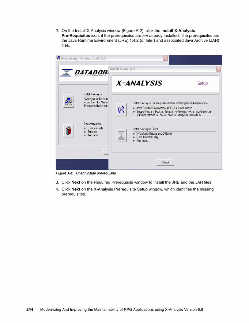
2. On the Install X-Analysis window (Figure A-2), click the Install X-Analysis Pre-Requisites icon, if the prerequisites are not already installed. The prerequisites are the Java Runtime Environment (JRE) 1.4.2 (or later) and associated Java Archive (JAR) files.
Figure A-2 Client install prerequisite
3. Click Next on the Required Prerequisite window to install the JRE and the JAR files.
4. Click Next on the X-Analysis Prerequisite Setup window, which identifies the missing prerequisites.
244 Modernizing And Improving the Maintainability of RPG Applications using X-Analysis Version 5.6

5. When the prerequisite install is complete, the X-Analysis Pre-Requisite Setup window indicates that the missing components have been installed (Figure A-3). The Action column in the PreRequisites table identifies the status of components installed. Click Finish to complete the X-Analysis client installation.
Figure A-3 Prerequisites installed
6. On the X-Analysis PreRequisite Setup wizard, click Next.
7. On the Select Installation Folder window, you can specify the location of the X-Analysis software. We used the default folder provided (C:\Program Files\Databorough). Click Next.
8. On the Read to Install window, click Install.
9. On the Completing the X-Analysis PreRequisite Setup Wizard window, click Finish to exit this portion of the setup wizard.
Appendix A. Getting started with X-Analysis 245

Installing the X-Analysis clientThe following steps are used to install the X-Analysis software on the client:
1. To start the installation, click the Install X-Analysis icon on the initial Databorough install window (Figure A-4).
Figure A-4 Main install window
2. On the X-Analysis Setup window, click the Install X-Analysis icon.
3. Click Next on the Welcome to X-Analysis Setup Wizard.
4. Click Install on the X-Analysis Setup (Ready to Install) window.
5. On the Completing the X-Analysis Setup Wizard window, click Finish to exit the setup wizard.
6. If you want to install the product documentation, the Databorough Product Suite is still active, either click the Documentation icon (to install the documentation) or click Exit to end the program. We chose to click Exit to end the program.
Configuring X-Analysis on the client
Before you can use X-Analysis, it must be configured by performing the following steps:1. To start the configuration on your PC, select Start → Programs → X-Analysis →
X-Analysis Configurator.
246 Modernizing And Improving the Maintainability of RPG Applications using X-Analysis Version 5.6
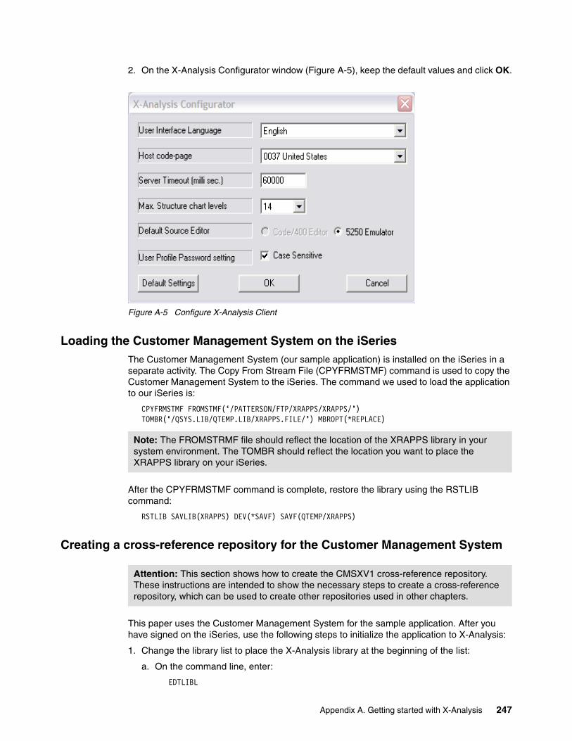
2. On the X-Analysis Configurator window (Figure A-5), keep the default values and click OK.
Figure A-5 Configure X-Analysis Client
Loading the Customer Management System on the iSeriesThe Customer Management System (our sample application) is installed on the iSeries in a separate activity. The Copy From Stream File (CPYFRMSTMF) command is used to copy the Customer Management System to the iSeries. The command we used to load the application to our iSeries is:
CPYFRMSTMF FROMSTMF(‘/PATTERSON/FTP/XRAPPS/XRAPPS/’) TOMBR(‘/QSYS.LIB/QTEMP.LIB/XRAPPS.FILE/’) MBROPT(*REPLACE)
After the CPYFRMSTMF command is complete, restore the library using the RSTLIB command:
RSTLIB SAVLIB(XRAPPS) DEV(*SAVF) SAVF(QTEMP/XRAPPS)
Creating a cross-reference repository for the Customer Management System
This paper uses the Customer Management System for the sample application. After you have signed on the iSeries, use the following steps to initialize the application to X-Analysis:
1. Change the library list to place the X-Analysis library at the beginning of the list:
a. On the command line, enter:
EDTLIBL
Note: The FROMSTRMF file should reflect the location of the XRAPPS library in your system environment. The TOMBR should reflect the location you want to place the XRAPPS library on your iSeries.
Attention: This section shows how to create the CMSXV1 cross-reference repository. These instructions are intended to show the necessary steps to create a cross-reference repository, which can be used to create other repositories used in other chapters.
Appendix A. Getting started with X-Analysis 247
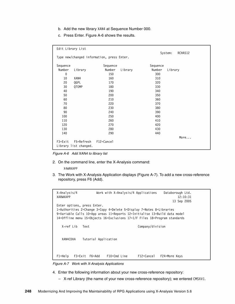
b. Add the new library XAN4 at Sequence Number 000.
c. Press Enter. Figure A-6 shows the results.
Figure A-6 Add XAN4 to library list
2. On the command line, enter the X-Analysis command:
X4WRKAPP
3. The Work with X-Analysis Application displays (Figure A-7). To add a new cross-reference repository, press F6 (Add).
Figure A-7 Work with X-Analysis Applications
4. Enter the following information about your new cross-reference repository:
– X-ref Library (the name of your new cross-reference repository); we entered CMSXV1.
Edit Library List System: RCHAS12 Type new/changed information, press Enter. Sequence Sequence Sequence Number Library Number Library Number Library 0 150 300 10 XAN4 160 310 20 QGPL 170 320 30 QTEMP 180 330 40 190 340 50 200 350 60 210 360 70 220 370 80 230 380 90 240 390 100 250 400 110 260 410 120 270 420 130 280 430 140 290 440 More... F3=Exit F5=Refresh F12=Cancel Library list changed.
X-Analysis/4 Work with X-Analysis/4 Applications Databorough Ltd. XARWKAPP 12:10:31 13 Sep 2005 Enter options, press Enter. 1=Authorities 2=Change 3=Copy 4=Delete 5=Display 7=Notes 8=Libraries 9=Variable Calls 10=App areas 11=Reports 12=Initialise 13=Build data model 14=Offline menu 15=Objects 16=Exclusions 17=I/F Files 18=Program standards X-ref Lib Text Company/division
XAN4CDXA Tutorial Application
F1=Help F3=Exit F6=Add F10=Cmd Line F12=Cancel F24=More Keys
248 Modernizing And Improving the Maintainability of RPG Applications using X-Analysis Version 5.6

– Text (a brief description; we entered CMS x-ref version 1.
– For Company/division, we entered ITSO.
– For Index source files, enter A for All.
– For Process var & bound calls, enter Y (Yes).
Press Enter.
Figure A-8 Create a cross-reference repository
5. The new cross-reference repository is added to the application library list. You see the message Application Added on the Work with X-Analysis/4 Applications screen.
6. To assign the source and object libraries, select option 8 (Libraries) beside CMSXV1.
7. To add the source and object libraries for the CMS application:
a. Press F6 (Add) to get the detail screen. To add the Source (on the Work with X-Analysis/ 4 Application Libraries detail screen), enter the following:
i. Type is S (source).
ii. Sequence is 1.00.
iii. Library is XRAPPS.
iv. Press Enter. The Work with X-Analysis/4 Application Libraries screen appears with the source library added. At the bottom of the screen you see the message Record Added.
b. Press F6 (Add) to get the detail screen. To add the Object (on the Work with X-Analysis/4 Application Libraries detail screen), enter the following:
i. Type is O (object).
ii. Sequence is 1.00.
iii. Library is XRAPPS.
iv. Press Enter. The Work with X-Analysis/4 Application Libraries screen appears with the object library added. At the bottom of the screen you see the message Record Added.
Figure A-9 shows both the source and object library added to the cross-reference repository.
X-Analysis/4 Work with X-Analysis/4 Applications Databorough Ltd. XARWKAPP 15:26:12 13 Sep 2005 X-ref Library. . . . . . . . . CMSXV1 Text . . . . . . . . . . . . . CMS x-ref version 1 Company/division . . . . . . . ITSO Index src files. . . . . . . . A Process var & bound calls. . . Y Include obsolete source . . . Build data model . . . . . . . Data model match value . . . TCPIP address . . . . . . . . User iD . . . . . . . . . . .
F1=Help F3=Exit F12=Cancel
Appendix A. Getting started with X-Analysis 249

8. Press F12 (Cancel) to return to the main Work with X-Analysis/4 Application Libraries screen.
Figure A-9 XRAPPS source and object libraries are added
Initializing the cross-reference repository for the Customer Management SystemTo initialize the cross-reference repository for the Customer Management System, perform the following steps:
1. On the Work with X-Analysis/4 Application screen, select option 12 (Initialize) next to the CMSXV1.
2. On the Initialise X-Analysis/4 screen (Figure A-10), press Enter.
Figure A-10 Initialize the application model
X-Analysis/4 Work with X-Analysis/4 Application Libraries Databorough Ltd. XARWKLIB 15:39:47 13 Sep 2005 Selected x-ref Library -> : CMSXV1 Enter options, press Enter. 2=Change 4=Delete 5=Display Type Sequence Library S 1.00 XRAPPS O 1.00 XRAPPS
F1=Help F3=Exit F6=Add F12=Cancel F16=Print
Initialise X-Analysis/4 (XA4INITP) Type choices, press Enter. Library for X-Ref database . . . > CMSXV1 Name Submit job . . . . . . . . . . . *YES *YES, *NO
Bottom F3=Exit F4=Prompt F5=Refresh F12=Cancel F13=How to use this display F24=More keys
250 Modernizing And Improving the Maintainability of RPG Applications using X-Analysis Version 5.6

3. On the Initialise X-Analysis/4 detail screen (Figure A-11), accept the default values. Press Enter to submit a batch job.
Figure A-11 Details of batch job
You are returned to the Work with X-Analysis/4 Applications screen. You see the message Job successfully submitted.
Generating the data model for the Customer Management SystemTo create a data model for the Customer Management System, perform the following steps:
1. On the Work with X-Analysis/4 Applications screen, select option 13 (Build data model) beside CMSXV1.
2. On the Initialise Data Model screen (Figure A-12), accept the defaults and press Enter.
Figure A-12 Submit batch job for creating the data model
Initialise X-Analysis/4 (XA4INIT) Type choices, press Enter. X-Analysis Library . . . . . . . > CMSXV1 Name Object Libraries . . . . . . . . > XRAPPS Name + for more values Source Libraries . . . . . . . . > XRAPPS Name, *NONE + for more values Index Source Files . . . . . . . > *ALL *CHG, *NO, *ALL, *UPG Include obsolete source . . . . *NO *YES, *NO Process variable & bound CALLS > *YES *YES, *NO, *ALL, *SRC Non AS/400 Code TCPIP Address . *NONE
Bottom F3=Exit F4=Prompt F5=Refresh F12=Cancel F13=How to use this display F24=More keys
Initialise Data Model (XDMODELP) Type choices, press Enter. Library for X-Ref database . . . > CMSXV1 Name Submit job . . . . . . . . . . . *YES *YES, *NO
Bottom F3=Exit F4=Prompt F5=Refresh F12=Cancel F13=How to use this display F24=More keys
Appendix A. Getting started with X-Analysis 251

3. On the Generate Prototype Application (XDMODEL) screen (Figure A-13), accept the default values and press Enter.
Figure A-13 Verify job details
On the Work with X-Analysis/4 Libraries screen, you see the message Job successfully submitted.
Giving designer authorityIn order to work with the cross-reference repository, you must be authorized. On the Work with X-Analysis/4 Applications screen, perform the following steps to get authorized:
1. Select option 1 (Authorities) for CMSXV1.
2. On the Work with Authorities screen, press F6 (Add) to add your user information.
3. On the Work with Authorities detail screen (Figure A-14), enter the following information:
a. For User profile, enter your user ID. We entered LINDAMAY.
b. For Designer, enter Y (yes) to give yourself designer authority.
c. For Allow to change Help Text, enter Y (yes).
d. For Design level, enter A (All).
e. For Security level enter A (All).
f. Press Enter.
Generate Prototype Application (XDMODEL) Type choices, press Enter. Function Library . . . . . . . . > CMSXV1 Name Add/replace model data . . . . . *REPLACE *ADD, *REPLACE Site Library . . . . . . . . . . *FUNLIB Name, *FUNLIB Add/replace site data . . . . . *REPLACE *ADD, *REPLACE Function type . . . . . . . . . > *GRIDS *GRIDS, *LISTS, *NONE X-Analysis Application Area . . *ALL Name, *ALL Data Libraries . . . . . . . . . > XRAPPS Name + for more values Synon Model Libraries . . . . . *NONE Character value, *NONE + for more values Derive Foreign Keys . . . . . . > *PGMLOGIC *DATABASE, *DATABASEA... Tolerance Value . . . . . . . . *NOMAX Number, *NOMAX Allow unmatched field names . . *PREFIX *ALL, *PREFIX, *PREFIX3... Use ref. fields for deriving . . *NO *NO, *EXACT, *PREFIX, *SUFFIX Use field texts for deriving . . *NO *AND, *OR, *NO Overrides Library/Diagrammer . . *DGM Name, *DGM, *FUNLIB More... F3=Exit F4=Prompt F5=Refresh F12=Cancel F13=How to use this display F24=More keys
252 Modernizing And Improving the Maintainability of RPG Applications using X-Analysis Version 5.6
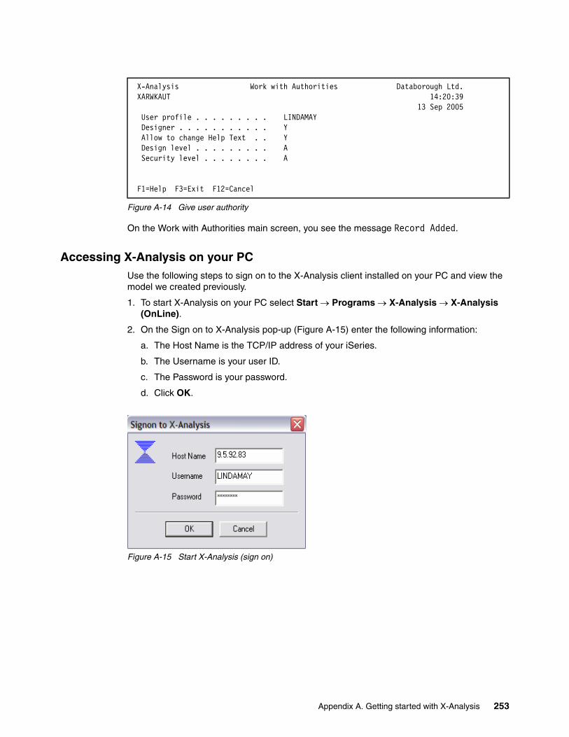
Figure A-14 Give user authority
On the Work with Authorities main screen, you see the message Record Added.
Accessing X-Analysis on your PCUse the following steps to sign on to the X-Analysis client installed on your PC and view the model we created previously.
1. To start X-Analysis on your PC select Start → Programs → X-Analysis → X-Analysis (OnLine).
2. On the Sign on to X-Analysis pop-up (Figure A-15) enter the following information:
a. The Host Name is the TCP/IP address of your iSeries.
b. The Username is your user ID.
c. The Password is your password.
d. Click OK.
Figure A-15 Start X-Analysis (sign on)
X-Analysis Work with Authorities Databorough Ltd. XARWKAUT 14:20:39 13 Sep 2005 User profile . . . . . . . . . LINDAMAY Designer . . . . . . . . . . . Y Allow to change Help Text . . Y Design level . . . . . . . . . A Security level . . . . . . . . A
F1=Help F3=Exit F12=Cancel
Appendix A. Getting started with X-Analysis 253

3. The X-Analysis List of Application Libraries window appears, displaying the available repositories (Figure A-16).
Figure A-16 View CMSXV1 model
4. To expand the model to see the details, click the plus sign (+) beside CMSXV1. Figure A-17 shows the various types of components contained within the model. To explore the model further, you can double-click any of these components.
Figure A-17 View CSMV1 detail
Installing the X-Web Server and Apache TomcatTo execute a re-engineered Web-enabled application, a Web server is required. The X-Analysis CD includes the X-Web Server and the Apache Tomcat servlet container. Before you can use the X-Web Server and Apache Tomcat, you must install them on your PC by performing the following activities:
� Unzip the installer to your PC.� Run the setup utility.� Install Apache Tomcat.� Install the X-Web server.
The X-Web Server installer is a zipped file on the X-Analysis installation CD. Perform the following steps for the installation:
1. On your PC, create a new directory within the Program Files directory, as follows:
a. Open an Explorer window.
254 Modernizing And Improving the Maintainability of RPG Applications using X-Analysis Version 5.6

b. Expand the C: drive.
c. Select the Program Files → Databorough directory.
d. Create a new folder and name it X-Web Server.
2. Copy and unpack the X-Web installation file using the following steps:
a. Insert the X-Analysis installation CD in your CD drive.
b. Open the root directory of the CD and locate the X-Web_5.6.7.zip file.
c. Copy the zip file to the X-Web Server folder.
d. Unpack the zip file into the X-Web Server folder.
3. Run the X-Web Server setup utility, as follows:
a. Locate and run the Setup.exe file located in the X-Web Server folder.
b. On the installation mode dialog box, select Full Installation.
c. Click OK.
4. The X-Web Server setup utility installs the Apache Tomcat servlet container, as follows:
a. In the Apache Tomcat Installer dialog box (Figure A-18), set the X-Web Server port field to 80.
b. Leave the remaining fields at the defaults.
c. Click OK.
Figure A-18 Apache Tomcat Installer
d. When the installation of Apache Tomcat is complete, a dialog box appears with the message Apache’s Tomcat has been successfully installed. Click OK.
5. The X-Web Server setup utility next installs the X-Web Server by performing these steps:
a. Review the X-Web End User License Agreement. Click Next to accept and continue the installation.
b. Leave the installation parameters at the default values. Click Next to start the install.
c. X-Web Server installation begins. When the X-Web installation dialog box displays the message Installation completed, click Finish to complete the installation. The X-Web Server installation setup utility displays pop-up messages as it copies utilities, sets up shortcuts, and installs registry entries.
Appendix A. Getting started with X-Analysis 255

d. When the installation is complete, the X-Web Installation dialog box appears with the following essential status information (there may be additional messages particular to your PC):
The machine has following components:> Sun's Java Runtime Environment> Apache's Tomcat WebServer> Databorough's X-Browse> Databorough's X-Web
e. Click OK to exit the installation.
256 Modernizing And Improving the Maintainability of RPG Applications using X-Analysis Version 5.6

Appendix B. X-Analysis cross-reference repository details
This appendix contains detailed information about the X-Analysis cross-reference repository. You can use this information to create programs to access the repository for your own purposes. Most of the files are described in detail; the only omissions are temporary work files and files used to format data areas.
B
© Copyright IBM Corp. 2006. All rights reserved. 257
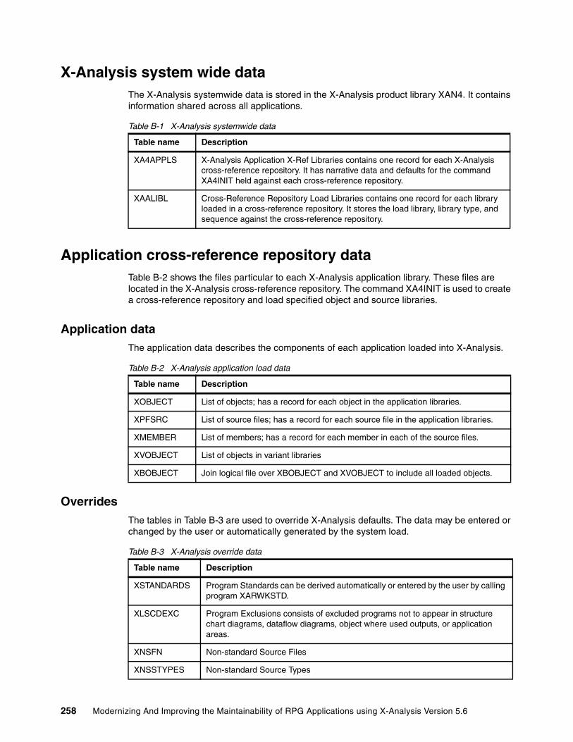
X-Analysis system wide dataThe X-Analysis systemwide data is stored in the X-Analysis product library XAN4. It contains information shared across all applications.
Table B-1 X-Analysis systemwide data
Application cross-reference repository dataTable B-2 shows the files particular to each X-Analysis application library. These files are located in the X-Analysis cross-reference repository. The command XA4INIT is used to create a cross-reference repository and load specified object and source libraries.
Application dataThe application data describes the components of each application loaded into X-Analysis.
Table B-2 X-Analysis application load data
OverridesThe tables in Table B-3 are used to override X-Analysis defaults. The data may be entered or changed by the user or automatically generated by the system load.
Table B-3 X-Analysis override data
Table name Description
XA4APPLS X-Analysis Application X-Ref Libraries contains one record for each X-Analysis cross-reference repository. It has narrative data and defaults for the command XA4INIT held against each cross-reference repository.
XAALIBL Cross-Reference Repository Load Libraries contains one record for each library loaded in a cross-reference repository. It stores the load library, library type, and sequence against the cross-reference repository.
Table name Description
XOBJECT List of objects; has a record for each object in the application libraries.
XPFSRC List of source files; has a record for each source file in the application libraries.
XMEMBER List of members; has a record for each member in each of the source files.
XVOBJECT List of objects in variant libraries
XBOBJECT Join logical file over XBOBJECT and XVOBJECT to include all loaded objects.
Table name Description
XSTANDARDS Program Standards can be derived automatically or entered by the user by calling program XARWKSTD.
XLSCDEXC Program Exclusions consists of excluded programs not to appear in structure chart diagrams, dataflow diagrams, object where used outputs, or application areas.
XNSFN Non-standard Source Files
XNSSTYPES Non-standard Source Types
258 Modernizing And Improving the Maintainability of RPG Applications using X-Analysis Version 5.6

User control dataThe tables in Table B-4 enable you to manipulate the application library into application areas. Many X-Analysis commands run on an application area. Projects that utilize this information could run for specific areas rather than the entire application.
Table B-4 X-Analysis user control data
Object dataThe tables in Table B-5 are derived from the object by using standard IBM commands or APIs.
Table B-5 X-Analysis object data
XPGREXCS Program Reference Exclusions; has programs such as APIs like QCMDEXC that are excluded from referencing.
XSRCPFEX Source file exclusions
XCMDEXCLS Command exclusions
XAXGENFILS Generic file data
XAXGENPGMS Generic program data
Table name Description
Table name Description
XAADESC Application Area Descriptions
XAALIST Application Area Objects
ARULES Application Area Rules
Table name Description
X@XPGRF Program Object References
X@XDBR Database relations
X@XRFMT Record Format Data
XLFFD File Field Data
XLBASATR Object Attribute Data
XTRIGGERS Trigger Data
XJOURNALS Journal Data
XCONSTRTS Constraint Data
XADDMFILS DM File Data
XAXCPP CMD Processor Data
XAXCVCP CMD Validity Checker Data
XAXMENU Menu Data
XVCONSTRTS Variant Library Constraint Data
Appendix B. X-Analysis cross-reference repository details 259

Table X@XPGRFTable X@XPGRF contains objects referenced by programs, commands, and menus. These references are retrieved primarily from object data. However, the source is also interpreted for additional references.
X@XPGRF and its equivalents (XVXPGREF and XPROCREF) are used to:
� Provide comprehensive Object Where Used data.� Allow complete investigation of program references.
Table B-6 X@XPGRF file layout
XVTRIGGERS Variant Library Trigger Data
XVXPGRF Variant Library Program Object References. There are variant versions of all programs that populate X@XPGRF.
Field name Datatype Length Description
WHPNAM CHAR 10 The name of the program, CMD or MENU
WHTEXT CHAR 50 The text held against WHPNAM
WHFNAM CHAR 11 The name of the referenced object
WHOBTP CHAR 1 The referenced object type:P - ProgramF- FileD - Data AreaC - Command
WUSAGE CHAR 1 The object type usage:I - Input FileU - Update/Input FileO - Output FileA - Input and Output FileB - Input and Output and Update FileC - Command calls command processing programV - Command calls validity checking programI - Program calls program or calls commandT - Trigger program input fileS - Trigger program update file
Notes: Remember:
� The object type of the WHPNAM field may be implied by the value of the WUSAGE. This is important when an object such as a program and a command have the same name. When WUSAGE = C or V, the WHPNAM object type is command; otherwise the WHPNAM object type is a program.
� Program in this case may indicate either a *PGM object or a *SRVPGM object.
� XVXPGREF is the equivalent file for variant libraries.
� XPROCREF is the equivalent file for OCL.
Table name Description
260 Modernizing And Improving the Maintainability of RPG Applications using X-Analysis Version 5.6
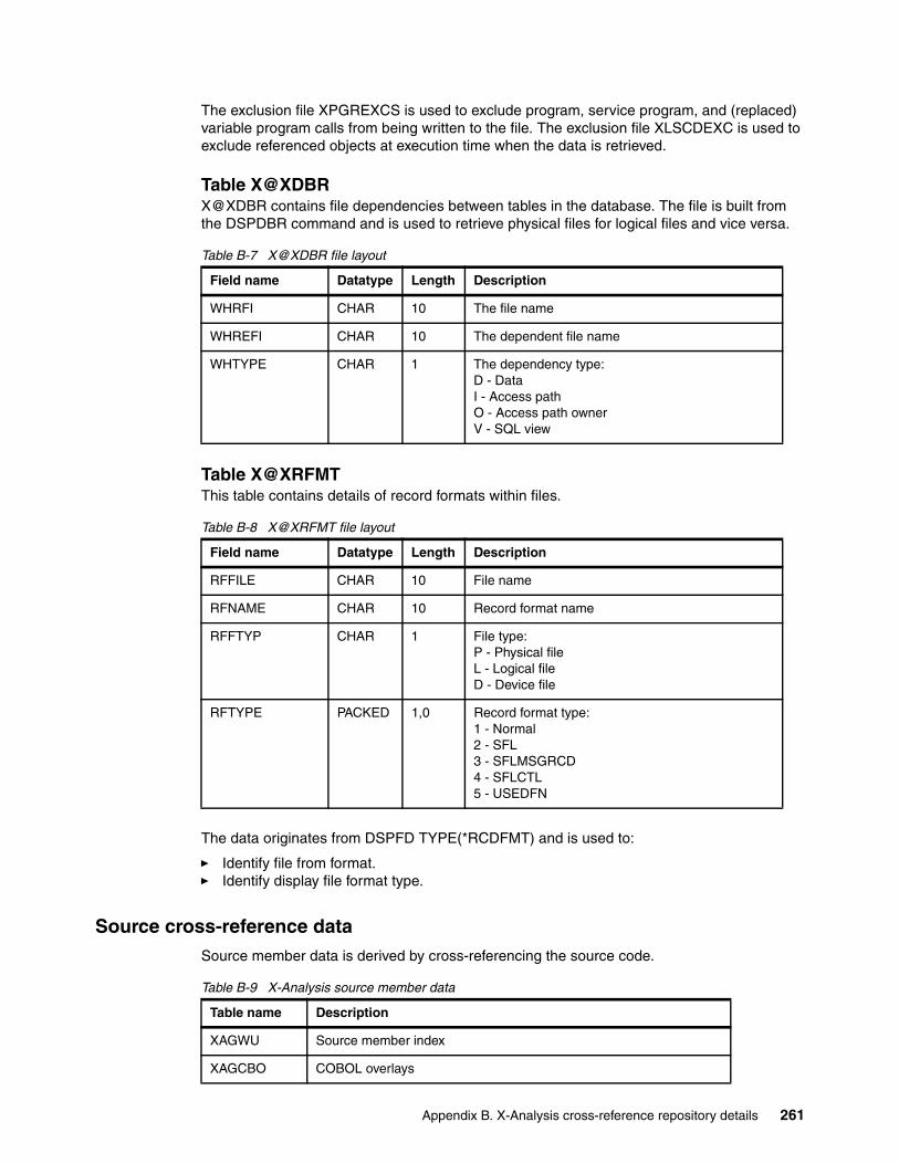
The exclusion file XPGREXCS is used to exclude program, service program, and (replaced) variable program calls from being written to the file. The exclusion file XLSCDEXC is used to exclude referenced objects at execution time when the data is retrieved.
Table X@XDBRX@XDBR contains file dependencies between tables in the database. The file is built from the DSPDBR command and is used to retrieve physical files for logical files and vice versa.
Table B-7 X@XDBR file layout
Table X@XRFMTThis table contains details of record formats within files.
Table B-8 X@XRFMT file layout
The data originates from DSPFD TYPE(*RCDFMT) and is used to:
� Identify file from format.� Identify display file format type.
Source cross-reference dataSource member data is derived by cross-referencing the source code.
Table B-9 X-Analysis source member data
Field name Datatype Length Description
WHRFI CHAR 10 The file name
WHREFI CHAR 10 The dependent file name
WHTYPE CHAR 1 The dependency type:D - DataI - Access pathO - Access path ownerV - SQL view
Field name Datatype Length Description
RFFILE CHAR 10 File name
RFNAME CHAR 10 Record format name
RFFTYP CHAR 1 File type:P - Physical fileL - Logical fileD - Device file
RFTYPE PACKED 1,0 Record format type:1 - Normal2 - SFL3 - SFLMSGRCD4 - SFLCTL5 - USEDFN
Table name Description
XAGWU Source member index
XAGCBO COBOL overlays
Appendix B. X-Analysis cross-reference repository details 261

The files in Table B-10 are lists of source members.
Table B-10 Lists of source members
Table XAGWU XAGWU (X-Analysis Where Used Data) is an index of each significant word in each source member with an allowable source type. The source member details are stored (library, file, member, type, relative record number (RRN)) together with the variable name, type, and whether modified. When used with alias and rename data, this enables instant cross-referencing of any variable type or constant against the entire application.
To retrieve an occurrence of a variable, use the source member details to open the source file member, then use the RRN to retrieve the individual source record. Use a standard procedure to interpret the source line. The source file attribute (VATTR) determines which standard procedure is used to interpret the source. For COBOL, the field sequence no. (VVARSQ) allows determination of the specific occurrence of the field in the statement. Where statements extend over several source lines, standard procedures are used to build the complete statements, reading both backward and forward through the source member.
Table B-11 XAGWU file layout
XAGCBQ COBOL qualifiers
XAXPGREF Program references from source
X@XCPYB /COPY references by member
X@XDSPF Device files by member
X@XPRXM Procedures by member
XAXPROTO Prototypes by member
XAXFMTR Format renames by member
XRFPREFX Field renames by member
XAXMFF File/format name/rename by member
XAFALIAS Field aliases
XPROCREF OCL procedure references
XCLOVRS CL overrides
XCONCATS Field concatenation data
XVPGREF Program references from variant source
Table name Description
XLSRCMBR Source Member Data
X4MEMBER Source Member Index Control
Field name Datatype Length Description
VSRCLB CHAR 10 Source library
VSRCFL CHAR 10 Source file
Table name Description
262 Modernizing And Improving the Maintainability of RPG Applications using X-Analysis Version 5.6

Table X@XCPYBX@XCPYB holds details of /COPY references within source members
Table B-12 X@XCPYB file layout
VSRCMB CHAR 10 Source member
VOBTY CHAR 2 Variable type:AA - Start of program logic sectionCL - Called programCN - Constant/literalEF - Externally defined data structureIN - IndicatorPI - Procedure interface definitionSR - Start of ILE RPG subroutine, COBOL section, or paragraph
VRECN PACKED 5,0 RRN where the variable occurs in the source member
VMOD CHAR 1 Indicates whether the variable is modified or not - if relevant
VATTR CHAR 2 Indicates the source member attribute:CL - CL variant (CLP, CL, CLLE)RG - RPG variant (RPG, RPG38, SQLRPG)RI - RPGLE variant (RPGLE, SQLRPGLE)CB - COBOL variant (CBL)PF - PF variantLF - LF variantDS - DSPF variantPR - PRTF variantOC - OCLSQ - SQLUS - User SpaceAL - Alias only record (allows references to a variable to be retrieved when it only occurs as an alias in a source member)
VVARSQ PACKED 5,0 The sequence number (position) of the variable within the source statement (or the part of it that is on the source line if the statement extends over more than one line). This only applies to COBOL and free-format ILE RPG.
Field name Datatype Length Description
PGMMBR CHAR 10 The source member containing the reference
PGMFIL CHAR 10 The source file containing the source member
PGMLIB CHAR 10 The library containing the source file
CPYMBR CHAR 10 The source member referenced by /COPY
CPYFIL CHAR 10 The source file containing the referenced source member
CPYLIB CHAR 10 The library containing the referenced source file
Restriction: The CPYFIL and CPYLIB fields cannot be relied on to contain values. The program X@RSRCF can be called to ensure that the correct values are retrieved.
Field name Datatype Length Description
Appendix B. X-Analysis cross-reference repository details 263

Table X@XDSPFTable X@XDSPF holds references to device files by source member.
Table B-13 X@XDSPF file layout
Table X@XPRXM Table B-14 table contains ILE RPG procedures by Member.
Table B-14 X@XPRXM file layout
The cross-indexing process also writes records to XAXPROTO. This contains the prototype name versus the exported procedure name. These two files enable the tracking of prototyped procedures and programs.
Derived dataThe tables in Table B-15 are derived by X-Analysis from the source and object data.
Table B-15 X-Analysis derived data
Field name Datatype Length Description
PGMMBR CHAR 10 The source member containing the reference
PGMFIL CHAR 10 The source file containing the source member
PGMLIB CHAR 10 The library containing the source file
DSPMBR CHAR 10 Is the source member of the device file
DSPFIL CHAR 10 The source file containing the referenced source member
DSPLIB CHAR 10 The library containing the referenced source file
Restriction: The DSPFIL and DSPLIB fields cannot be relied on to contain values. The program X@RSRCF can be called to ensure that the correct values are retrieved.
Field name Datatype Length Description
PRXMBR CHAR 10 The source member containing the procedure
PRXFIL CHAR 10 The source file containing the source member
PRXLIB CHAR 10 The library containing the source file
PRXPR CHAR 50 Has the name of the procedure
Table name Description
XAXFLOW Program flow data
XAXPFLOW Procedure flow data
XAXSCD Program SCD data
XLTXT Program narratives
XLENC Encyclopedia - Data modelling diagram interface
Note: A Global Where Used Workfile named XAGWUWK has no file layout information.
264 Modernizing And Improving the Maintainability of RPG Applications using X-Analysis Version 5.6
Appendix C. Additional material
This Redpaper refers to additional material that can be downloaded from the Internet as described below.
Locating the Web materialThe Web material associated with this Redpaper is available in softcopy on the Internet from the IBM Redbooks Web server. Point your Web browser to:
ftp://www.redbooks.ibm.com/redbooks/REDP4046
Alternatively, you can go to the IBM Redbooks Web site at:
ibm.com/redbooks
Select the Additional materials and open the directory that corresponds with the Redpaper form number, REDP4046.
Using the Web materialThe additional Web material that accompanies this Redpaper includes the following files:
File name Description
LIBRARYCMS.savf Sample library containing the sample application used in this paper. This library is for V5R2 of OS/400 or V5R3 of i5/OS.
CMS project.zip Sample Web project for the MVC re-engineering project.
xrefexampl.savf Sample ILE RPG source code that demonstrates how the X-Analysis Cross-Reference Repository can be used.
C
© Copyright IBM Corp. 2006. All rights reserved. 265

System requirements for downloading the Web materialThe following system configuration is recommended:
Hard disk space 190 MB minimumOperating System Windows 2000 ProfessionalProcessor Pentium® III or higherMemory 512 MB
How to use the Web materialTo use the Web material, follow the instructions in this section.
Restoring the LIBRARYCMS.SAVFSend by File Transfer Protocol (FTP) the libraryCMS.savf file to the iSeries server using the following example:
1. Create a save file in your library on the iSeries:
CRTSAVF QGPL/LIBRARYCMS
2. Transfer the downloaded save file to your iSeries library:
C:\>ftp yoursystemConnected to yoursystem.yourdomain.com.220-QTCP at yoursystem.yourdomain.com.220 Connection will close if idle more than 5 minutes.User (yoursystem.yourdomain.com.:(none)): youruserid331 Enter password.Password:yourpassword230 youruserid logged on.ftp> bin200 Representation type is binary IMAGE.ftp> put c:\yourDir\librarycms.savf /qsys.lib/qgpl.lib/librarycms.savf200 PORT subcommand request successful.150-NAMEFMT set to 1150 Sending file to member LIBRARYCMS in the LIBRARYCMS in library your library.250 File Transfer completed successfully.
3. End the FTP session by entering quit.
4. Sign on to the iSeries server and restore the save file:
RSTLIB SAVLIB(LIBRARYCMS) DEV(*SAVF) SAVF(QGPL/LIBRARYCMS) RSTLIB(XRAPPS)
Installing the CMS MVC re-engineering Web projectFollow these steps to install the application:
1. From the WebSphere Development Studio Client for iSeries tool bar, click File → Import.
266 Modernizing And Improving the Maintainability of RPG Applications using X-Analysis Version 5.6

2. On the Import window (Figure C-1), select Project Interchange Format and click Next.
Figure C-1 Import project into WDSc
Appendix C. Additional material 267
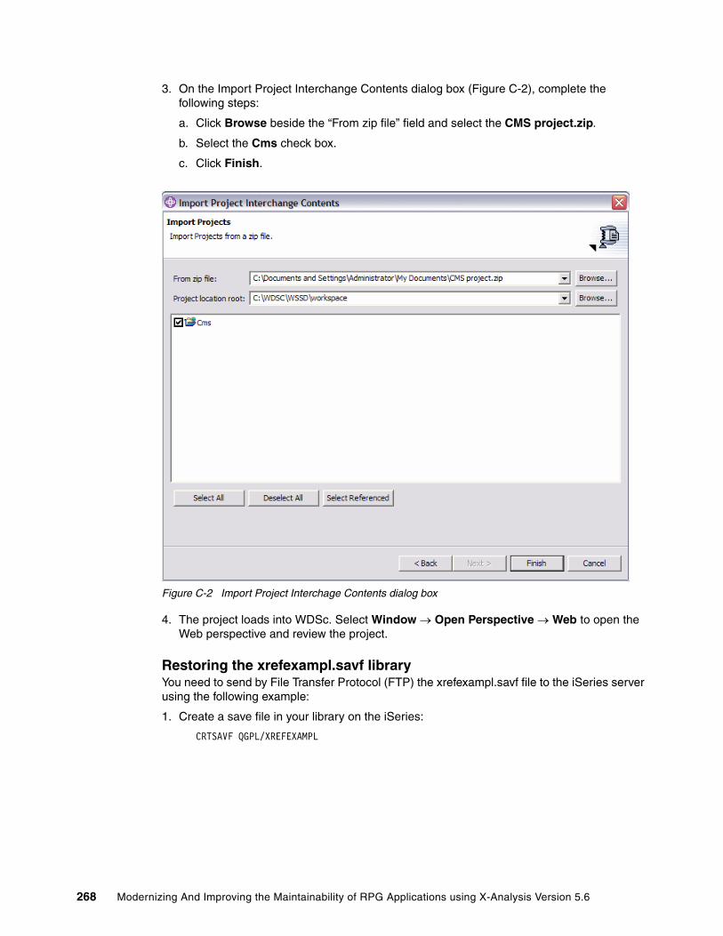
3. On the Import Project Interchange Contents dialog box (Figure C-2), complete the following steps:
a. Click Browse beside the “From zip file” field and select the CMS project.zip.
b. Select the Cms check box.
c. Click Finish.
Figure C-2 Import Project Interchage Contents dialog box
4. The project loads into WDSc. Select Window → Open Perspective → Web to open the Web perspective and review the project.
Restoring the xrefexampl.savf libraryYou need to send by File Transfer Protocol (FTP) the xrefexampl.savf file to the iSeries server using the following example:
1. Create a save file in your library on the iSeries:
CRTSAVF QGPL/XREFEXAMPL
268 Modernizing And Improving the Maintainability of RPG Applications using X-Analysis Version 5.6

2. Transfer the downloaded save file to your iSeries library:
C:\>ftp yoursystemConnected to yoursystem.yourdomain.com.220-QTCP at yoursystem.yourdomain.com.220 Connection will close if idle more than 5 minutes.User (yoursystem.yourdomain.com.:(none)): youruserid331 Enter password.Password:yourpassword230 youruserid logged on.ftp> bin200 Representation type is binary IMAGE.ftp> quote site namefmt 1250 Now using naming format "1".ftp> put c:\yourDir\xrefexampl.savf /qsys.lib/qgpl.lib/xrefexampl.file200 PORT subcommand request successful.150 Sending file to member XREFEXAMPL in file XREFEXAMPL in library QGPL.250 File transfer completed successfully.
3. End the FTP session by entering quit.
4. Sign on to the iSeries server and restore the save file:
RSTLIB SAVLIB(XREFEXAMPL) DEV(*SAVF) SAVF(QGPL/XREFEXAMPL) RSTLIB(XREFEXAMPL)
Two objects are restored to library XREFEXAMPL:
– QRPGLESRC: Contains the example source member XREFEXAMPL– XREFEXAMPL: Program object
Appendix C. Additional material 269

270 Modernizing And Improving the Maintainability of RPG Applications using X-Analysis Version 5.6
Related publications
The publications listed in this section are considered particularly suitable for a more detailed discussion of the topics covered in this Redpaper.
IBM RedbooksFor information on ordering these publications, see “How to get IBM Redbooks” on page 273. Note that some of the documents referenced here may be available in softcopy only.
� Modernizing IBM Eserver iSeries Application Data Access - A Roadmap Cornerstone, SG24-6393
� WebSphere Development Studio Client for iSeries Version 5.1.2, SG24-6961
� WebSphere Development Studio Client for iSeries: Bringing New Life into 5250 Applications, SG24-6600
� Managing Information Access to an Enterprise Information System Using J2EE and Services Oriented Architecture, SG24-6371
� Patterns: Implementing an SOA using an Enterprise Service Bus, SG24-6346
� Patterns: SOA with an Enterprise Service Bus in WebSphere Application Server V6, SG24-6494
� Student Edition: WebSphere Development Studio Client for iSeries V5.0, SG24-7086
� Enabling Web Services for the IBM Eserver iSeries Server, REDP-0192
� IBM Eserver i5 and iSeries System Handbook: IBM i5/OS Version 5 Release 3 October 2004, GA19-5486
� WebSphere for the IBM Eserver iSeries Server Buying and Selling Guide, REDP-3646
� Moving to Integrated Language Environment for RPG IV, GG24-4358
� Unleashing AS/400 Applications on the Internet, SG24-4935
� Who Knew You Could Do That with RPG IV? A Sorcerer's Guide to System Access and More, SG24-5402
� WebSphere Studio Application Developer Programming Guide, SG24-6585
� WebSphere Application Server V5 for iSeries: Installation, Configuration, and Administration, SG24-6588
� WebSphere Studio Application Developer Version 5 Programming Guide, SG24-6957
� WebSphere Application Server - Express V5.0 for iSeries, REDP-3624
Other publicationsThese publications are also relevant as further information sources:
� Java for RPG Programmers, Second Edition, by George Farr and Phil Coulthard. Mc Press, April 2002, ISBN193118206X
� VisualAge for RPG by Example, by Bryan Meyers and Jef Sutherland. 29th Street Press, April 1998, ISBN 1882419839
© Copyright IBM Corp. 2006. All rights reserved. 271

� Experience RPG IV Tutorial, by Heather Rogers and M. Masri. Advice Press, April 1999, ISBN 1889671223
� Programming with VisualAge RPG, SC09-2449
� VisualAge RPG Parts Reference, SC09-2450
� VisualAge RPG Language Reference, SC09-2451
� iSeries Performance Capabilities Reference, SC41-0607
Online resourcesThese Web sites and URLs are also relevant as further information sources:
� For more information about X-Analysis
http://www.databorough.com/
� WebSphere Development Studio Client for iSeries information and help
http://publib.boulder.ibm.com/infocenter/iadthelp/index.jsp
� iSeries Developer Roadmap
http://www.ibm.com/servers/eserver/iseries/roadmap
� Technical support and resources for iSeries and AS/400
http://www-912.ibm.com/
� Information about Model-View-Controller Architecture
http://java.sun.com/blueprints/patterns/MVC.html
� JavaServer Faces
http://java.sun.com/j2ee/javaserverfaces
� JavaBeans
http://java.sun.com/products/javabeans/index.jsp
� Apache Tomcat
http://jakarta.apache.org/tomcat
� Information about UML
http://www.uml.org
� WebSphere Studio Site Developer
http://www.ibm.com/software/ad/studiositedev
� WebSphere Studio Application Developer
http://www.ibm.com/software/ad/studioappdev
� WebSphere Application Server Version 4.0 Advanced Edition for iSeries
http://publib.boulder.ibm.com/was400/40/AE/english/docs
� iSeries Information Center
http://www.ibm.com/eserver/iseries/infocenter
Online TutorialsSeveral self study tutorials covering WDSc are available on the Internet:
� You can register for the Web-based Training Course SW738 Introducing IBM WebSphere Development Studio Client for iSeries at:
272 Modernizing And Improving the Maintainability of RPG Applications using X-Analysis Version 5.6

http://ibm.com/developerworks/websphere/library/tutorials/dl/sw738/
� There are also some tutorials provided with the online Help under Tutorials and samples. If you do not have WDSc installed on your workstation, you can also access the online help at:
http://publib.boulder.ibm.com/infocenter/iadthelp/index.jsp
How to get IBM RedbooksYou can search for, view, or download Redbooks, Redpapers, Hints and Tips, draft publications and Additional materials, as well as order hardcopy Redbooks or CD-ROMs, at this Web site:
ibm.com/redbooks
Help from IBMIBM Support and downloads
ibm.com/support
IBM Global Services
ibm.com/services
Related publications 273

274 Modernizing And Improving the Maintainability of RPG Applications using X-Analysis Version 5.6

Index
Numerics5250 function 40
Aabstract Java classes 8accessing X-Analysis client 253Account Maintenance 23
Web pages 87adjusting generated data model 205analysis performing 182analyze programs 134analyzing recompiled object 188Apache Tomcat
installing 254application
viewing of JSF 99Web enabling 80
application analysis 124application area 8, 40, 42, 197
adding Customers Main Menu 43creating 42data model diagram 124defining 197
application area level diagrams 124application boundaries 7application data model
exploring 200application design
recovering 195–196, 212application documentation 124Application Overview extension 10application partitioning 41application structure 3application versions 7architecture of modern application 4attract new developers 2authorizing designer 252automated application conversion 7automated modernization projects 7availability of tools 2
BBasic Site Configurator 82browser based application 5build global field usage (XBLDUSAGE) 191building object list
object list building 174business logic 3, 40
viewing 143business processes 11business rule
query 239recovering 214
© Copyright IBM Corp. 2006. All rights reserved.
viewing 143business rules database
using 229business rules extraction process 229
levels 229Business Rules Extractor 60business scenario 1 14business scenario 2 14business scenario 3 14
Ccall prototype 150CALLP 150change management 7, 10, 194changing size of selected field 171CMS project.zip
installing 266com.databorough.storedprocedure.access package 102component based architecture 3, 8, 13, 214componentization 3configuring X-Analysis client 246CONST keyword 150constructing a model 196controlled access 4controller 4conversion
running 177setting up 178
conversion listworking with 176
conversion process 7, 177verifying 183
conversion type 176convert program (XCVTPGMS) 182converted application 7creating
Model 38View and Controller 38
creating cross-reference repository 247creating Web-enabled application 80cross-reference repository 8
application data 258creating 247derived data 264details 147initializing 250introducing 114object data 259overrides 258user control data 259
cross-reference source data 261cross-referencing 9Customer Management System 197
loading 247
275
overview 16Customer Site Maintenance 18
Web pages 99Customer Sites Maintenance
Web pages 84Customers Main Menu 16, 41, 199
Account Maintenance 23Customer Site Maintenance 18data files 30Maintain Organizations 21programs 30Work with Customer Contacts 24Work with Customer Sites 25Work with Rep. Delivery Area 28
DData Definition Language 11Data Definition Language (DDL)
exporting 221data dictionary 225data flow diagram (DFD) 114, 124
object centered data flow diagram 125viewing 125
data model 8adjusting 205core tables 224exporting 220generating 251tuning 196types of relationships 202using 224
data model diagram (DMD) 124, 200database 8
exploring data via X-Analysis 208database warning report 190DB warnings report 190defining an application area 197delineated objects 7dependent buttons 69derived data 264deriving business rules 214designer authority
giving 252detailed structure chart
viewing 128development life cycle 7device file problems report 189DFD 124display file 8distributed systems 6Document Manager 130
marking 130documentation 14
application 124documentation wizard 10
using 132DSPDBR command 261
Eend user experience 11, 13entity relationship diagram (ERD) 124, 220, 223ERD 124explicitly identifying field change 167exploring application data model 200exploring data in database 208exporting DDL 221exporting Microsoft Visio 223exporting the data model 220exporting XMI 220
Ffield change
global usage 167identifying 162
field expansion 159, 173field length change 173field re-engineering
performing 159field resize 114, 159, 173
changing selected field 171field resizing 114file global usage 169flat screen function 40
customizing 55, 77for Contacts file 48for site maintenance program 67
flowchartin Microsoft Visio 143
foreign key reference 70value 209
Function Builder 45, 60, 64function definition 38
5250 function 40flat screen function 40linking 71list function 40prompt function 40pull-down selection list function 40types of 40
Function Definition Editor 40, 47function definitions
categories 40grid function 40JSF 93
function key 40, 69function layout
displaying 47viewing 65
future tools view 13
Ggenerating data model 251global field usage 167global usage of selected file
displaying 169grid function 40
customizing 49
276 Modernizing And Improving the Maintainability of RPG Applications using X-Analysis Version 5.6
for Contacts file 47grid re-engineered function definition
customizing 73for customer selection program 67
Iidentifying field change 167identifying field changes 162identifying potential problems 189ILE RPG 14impact analysis 114import converted library 194importing converted libary to change management 194indented source view 140initializing cross-reference repository 250installing Apache Tomcat 254installing CMS project.zip 266installing X-Analysis client 243installing X-Analysis on iSeries 243installing X-Web server 254iSeries Developer Roadmap 11–12iSeries Initiative for Innovation 12
JJava abstract classes 8, 94Java BluePrint 37Java components 93
customizing 96generating 94
Java Server Faces 93JavaBeans 8, 13, 39, 93JavaServer Faces 4, 8, 13, 39job 5JSF Generator 39, 93
Kkeyword match 162
LLIBRARYCMS.savf
restoring 266list function 40list of objects
building 174loading Customer Management System 247logical screen 65
MMaintain Organization 21
Web page 86maintainability 2, 196maintenance 14measuring referential integrity 211Member X-Ref 122member x-reference 137Microsoft Office 10Microsoft Visio 10
exporting 223flowchart 143
Microsoft Word 10documents 130
Modelaccess 39creating 38functionality 70
model 4modelling 196Model-View-Controller architecture 1, 4, 11, 37modern application 2
architecture 4modernization 1, 7, 15modernization scenarios 14modernize 1–2, 14
application modernization 16modernization 7modernization process 7reasons for 2
modified versions 7modular architecture 11, 13multi-tier architecture 4MVC 13–14MVC architecture 4MVC re-engineering
prerequisites 36summary 41
MVC re-engineering process 36, 38, 41running 60running over an individual program 62
Oobject centered data flow diagram 125object level diagrams 124object where used 125open interfaces 2OPM RPG 14overview structure chart (OSC)
using 212Overview Structure Charts (OSC) 124
Ppartitioning application 41performing analysis 182performing field re-engineering 159portability 2potential problems
identifying 189preparing for X-Analysis install 242print global field usage command (XPRTUSAGE) 191print preview 129printing diagrams 129process model 8productivity 11, 13program analysis and understanding 134program logic problems report 190program object reference 148program structure chart (PSC) 142
Index 277

program variable 5programming languages 11project sizing 114prompt function 40PSC 142pseudo code 10, 114, 143, 218pull-down selection list function 40
Qquery business rules 239
Rrecompile object 181
analyzing 188recompile only exercise
conducting 180recovering application design 195–196, 212recovering business rules 214Redbooks Web site 273
Contact us xiire-engineered function definition 40, 99
customizing 73generating 60naming conventions 65reviewing 64
re-engineered programs view 64re-engineered stored procedure 70
linking 71naming conventions 71reviewing 70source code 72, 105
re-engineering 8referential integrity 10
measuring 211relationship link 203resizing project
creating 160initializing 161
responsiveness to change 2restoring LIBRARYCMS.savf 266restoring xrefexampl.savf 268reusable components 3, 6, 148RFD 40rich client user interface 4, 39running conversion 177running search 166
Ssample application 16
introducing 15sample utility program 150scalability 4SCD 124search criteria 163search exclusion 166searching
keyword match 162multiple search words 165
running search 166search criteria 163search exclusion 166search word 163setting up 162
security 4service-oriented architecture (SOA) 6services 6set up conversion 178set up searches 162setting up search 162SFD 40single source member 3six pillars 11SOA 6Source Browser 134source code 8, 140
pseudo code viewing 141re-engineering store procedure 72viewing 138
source code changesverifying 183
source file references report 193source listing
view 135SQL 4standard function definition 40standard function definitions
customizing 49generation 45reviewing 45viewing 45
starting X-Analysis client 115stateless programs 5
state information 5stored procedure 8, 38, 47, 70
ZZCUSFMAIN 105Stored Procedure Generator 60structure chart diagram (SCD) 124
viewing 127Structured Query Language (SQL) 4, 221
Tthree tier architecture 4traditional 5250 application 5, 11trial conversion 7tuning the data model 196
UUnified Modeling Language (UML) 93–94update request
processing 103user interface 3
rich client user interface 4Web browser user interface 4
using the business rules database 229using the data model 224using X-Browse to explore data model 228utility program sample 150
278 Modernizing And Improving the Maintainability of RPG Applications using X-Analysis Version 5.6

Vvariable 5variable where used (VWU) 114, 136, 159
level 1 119level 2 119level 3 120level 4 120level 5 120level 6 121level 7 121viewing levels 1-7 115
verifying conversion process 183verifying source code changes 183view 4View and Controller
creating 38viewing data flow diagram 125viewing detailed structure chart 128viewing indented 140viewing pseudo code 141viewing source code 138viewing source listing 135viewing structure chart diagram 127viewing VWM level 5 120viewing VWU level 1 119viewing VWU level 2 119viewing VWU level 3 120viewing VWU level 4 120viewing VWU level 6 121viewing VWU level 7 121VWU
viewing levels 115
WWDSc 93
running 96working with Java components 96
Web browser user interface 4, 39Web material
download requirements 266locating 265using 265
Web-enabled applicationcreating 80starting 83
WebSphere Studio Site Developer (WSSD)starting 95
where used data 149Work with Customer Contacts 24
Web pages 90Work with Customer Contract 47Work with Customer Sites 25Work with Rep. Delivery Area 28Work with X-Resize Projects screen 178workfield conflict report 192working with conversion list 176workspace 97
XX@XCPYB table 263X@XDBR table 261X@XDSPF table 264X@XPGRF table 148, 260X@XPRXM table 264X@XRFMT table 261XAGWU table 149, 262X-Analysis 1, 13, 16, 114
components 9extensions 9foundation product 9Function Builder 45installing on iSeries 243introducing 8preparing for install 242set up 242system wide data 258X-Analysis client 8
X-Analysis client 8, 206accessing 253configuring 246installing 243starting 115
X-Archive 10XBLDLISTS 175XBLDUSAGE (build global field usage) 191X-Browse 10, 36, 39, 196, 208
using 228XCMMENU 199X-Control 10XCVTPGMS (convert program) 182XDD table 225XDMODEL command 196XERRIND table 229XEXBIZRLES table 238XEXEXTLGC table 238XEXFLDCMPS table 230XEXFLDRNGS table 230XEXFLDTRKR table 231XEXFLDVALS table 231XEXOTHFILS table 237XEXPGMBLKS table 231XEXPGMCTAS table 234XEXPGMFLDS table 232XEXPGMLSTS table 233XEXPGMMGSS table 233XEXPGMSTTS table 234XEXPMTFLDS table 234XEXRTNCDES table 235XEXSELPGMS table 235X-Extract 10, 36XEXTRGLINS table 236XEXUPDFUN table 235XEXVALFLGS table 236XKEYMAP table 228XMI
exporting 220X-Migrate 11, 36XML Metadata Interchange (XMI) 11
Index 279
XPIDS table 224XPRTUSAGE (print global field usage) 191XRAPPS 16
data files 31library 31source and object files 32
xrefexampl details 150xrefexampl.savf
restoring 268XRELS table 227X-Resize 10, 178XRESIZEJOB 161X-Rev 9, 36, 196XRRCFERR 188XRRCVERR 188XSHKEYS table 227X-Subset 10X-Verify 10XVERIFY command 211
parameters 211X-Web framework 39, 80
using 80X-Web server 36, 80
authority 37configuring 81installing 254starting 81
280 Modernizing And Improving the Maintainability of RPG Applications using X-Analysis Version 5.6

®
INTERNATIONAL TECHNICALSUPPORTORGANIZATION
BUILDING TECHNICAL INFORMATION BASED ON PRACTICAL EXPERIENCE
IBM Redbooks are developed by the IBM International Technical Support Organization. Experts from IBM, Customers and Partners from around the world create timely technical information based on realistic scenarios. Specific recommendations are provided to help you implement IT solutions more effectively in your environment.
For more information:ibm.com/redbooks
Redpaper
Modernizing and Improving the Maintainability of RPG Applications Using X-Analysis Version 5.6
Graphically analyze application architecture
Extract business rule logic and application data models
Modularize existing code into the MVC architecture
This IBM Redpaper covers the use of X-Analysis to accelerate the modernization and improve the maintainability of existing RPG applications. It discusses how X-Analysis is used to restructure and reuse the RPG application’s business logic and application data model, and includes step-by-step examples and scenarios showing an RPG application exposed by the tool. The paper shows how an application is visually displayed, starting from a high-level model and drilling down to program details such as the specific use of fields and files.
Use of X-Analysis to convert an existing application to the Model-View-Controller architecture is explained. In this instance, the View and Controller portions of the application are converted to JavaServer Faces and JavaBeans. X-Analysis takes advantage of the implicit data and process model in the application to create individually callable pieces of business logic.
This paper explores many of the capabilities available in X-Analysis and shows you how to write programs to use information stored in the cross-reference repository. You can use this information to simplify and automate your conversion process.
If you are thinking about modernization or maintainability, and want to accelerate the process, this is the Redpaper for you.
Back cover