modification of fuel for increasing the power of paks units botond beliczai pa zrt. nufo rfo 2009
TRANSCRIPT

Modification of fuel for increasing the power of
Paks units
Botond BeliczaiPA Zrt. NUFO RFO
2009.

Increasing the lattice pitch and its effectProfiled enrichment
4th unit 23rd cycle subchannel outlet
temperature values applying fuel assemblies
with different lattice pitch
1 306.8
2 302.4
3 301.6
4 301.6
5 301.3
6 300.8
7 301.1
8 305.1
9 302.6
10 311.5
11 311.5
12 313.1
13 311.7
14 313.4
15 311.6
16 312.9
17 311.3
18 312.7
19 310.9
20 311.9
21 310.0
22 309.7
23 301.1
24 302.1
25 312.3
26 313.4
27 313.6
28 313.4
29 313.0
30 313.1
31 312.3
32 312.6
33 312.0
34 312.5
35 312.0
36 312.2
37 312.1
38 311.7
39 310.2
40 300.5
41 302.3
42 312.8
43 314.1
44 313.7
45 313.3
46 312.2
47 312.0
48 311.2
49 311.3
50 310.6
51 310.9
52 310.5
53 311.1
54 310.8
55 311.8
56 311.9
57 312.0
58 310.3
59 300.5
60 302.4
61 312.7
62 314.1
63 313.6
64 313.0
65 311.8
66 311.4
67 310.6
68 310.5
69 310.0
70 310.1
71 309.7
72 309.9
73 309.7
74 310.2
75 310.2
76 311.2
77 311.5
78 311.6
79 310.1
80 300.2
81 302.2
82 312.5
83 314.4
84 313.9
85 313.1
86 311.9
87 311.3
88 310.5
89 310.3
90 309.8
91 309.7
92 308.4
93 309.4
94 309.2
95 309.4
96 309.4
97 309.8
98 310.0
99 310.9
100 311.4
101 311.5
102 309.7
103 299.8
104 302.8
105 312.1
106 313.8
107 313.9
108 313.5
109 312.4
110 311.6
111 310.7
112 310.3
113 309.9
114 308.6
115 303.2
116 302.9
117 302.5
118 308.1
119 309.0
120 309.2
121 309.2
122 309.7
123 310.1
124 311.0
125 311.1
126 310.7
127 308.9
128 300.3
129 304.3
130 307.5 131
302.8
132 312.0
133 313.7
134 313.9
135 313.4
136 312.3
137 311.4
138 310.6
139 310.2
140 309.8
141 308.5
142 302.9
143 302.6
144 302.6
145 307.8
146 308.9
147 309.0
148 309.2
149 309.5
150 310.1
151 310.8
152 311.0
153 310.5
154 308.9
155 300.2
156 302.0
157 312.3
158 313.9
159 313.6
160 312.7
161 311.6
162 310.8
163 310.2
164 309.9
165 309.5
166 309.3
167 308.2
168 309.0
169 308.9
170 309.0
171 309.0
172 309.3
173 309.6
174 310.4
175 311.1
176 311.2
177 309.4
178 299.6
179 302.0
180 312.2
181 313.4
182 313.0
183 312.3
184 311.2
185 310.7
186 310.0
187 309.8
188 309.5
189 309.4
190 309.2
191 309.2
192 309.1
193 309.5
194 309.6
195 310.4
196 310.7
197 311.0
198 309.6
199 299.8
200 301.8
201 311.9
202 313.3
203 312.9
204 312.4
205 311.3
206 311.1
207 310.3
208 310.3
209 309.8
210 310.0
211 309.7
212 310.1
213 310.1
214 310.8
215 311.1
216 311.2
217 309.6
218 299.8
219 301.3
220 311.4
221 312.4
222 312.6
223 312.4
224 312.0
225 312.0
226 311.3
227 311.5
228 310.9
229 311.5
230 311.0
231 311.1
232 311.0
233 310.6
234 309.4
235 299.6
236 301.7
237 310.7
238 310.4
239 312.0
240 310.6
241 312.2
242 310.6
243 311.7
244 310.3
245 311.6
246 309.8
247 310.7
248 309.0
249 309.0
250 300.2
251 305.6
252 301.6
253 300.8
254 300.7
255 300.3
256 299.9
257 300.4
258 304.4
TsubOutCO[C] data
Sector/Assembly Num: 1/12
Axial Layer: 1
1
TsubOutCO[C]:
316.13:317.52 314.73:316.13 313.34:314.73 311.94:313.34 310.55:311.94 309.15:310.55 307.76:309.15 306.37:307.76 304.97:306.37 303.58:304.97 302.18:303.58 300.79:302.18 299.39:300.79 298.00:299.39 296.60:298.00
Assembly 12.2 mm lattice pitch
12.3 mm lattice pitch
Difference
12 314.4 C 312.9 C - 1.5 C
26 315.0 C 313.4 C - 1.6 C
38 308.6 C 307.3 C - 1.3 C
56 287.8 C 287.1 C - 0.7 C

Geometry of Hf-layer in the CFA

Effect of applying Hf-layer in the CFA
Decreasing the power peak in the pin next to the CFA
Axial distribution of the linear heat rate
0
50
100
150
200
250
300
0 5 10 15 20 25 30 35 40 45
Axial layer
Lin
ear
hea
tra
te(W
/cm
)
Without Hf
With Hf
Axial distribution of the linear heat rate
0
50
100
150
200
250
300
0 5 10 15 20 25 30 35 40 45
Axial layer
Lin
ear
hea
tra
te(W
/cm
)
Without Hf
With Hf

Purpose of modification: helping in the increase of heat power
• Increasing the subchannel outlet temperature reserve for 8 % heat power increase:5 ( 4+1) C
Sources of increasing the subchannel outlet temperature reserve : • Change in the pressure control: 1 C• VERONA upgrade + modified engineering limits 1.5 C• Modified fuel 1.5 CAlltogether 4 COther sources:
More conservative reload patternReduced pressure in the secondary circuitApplying a mixing modell inside the FA
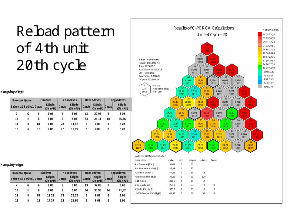
Reload patternof 4th unit 20th cycle
1
22,74 1007
2
13,64 1011
3
11,09 1011
4
21,00 1007
5
11,09 1011
6
20,20 1010
7
13,21 1013
8
24,24 1010
9
0,000 1011
10
24,90 1007
11
23,56 1010
12
23,39 1010
13
11,99 1011
14
7,749 1011
15
26,21 1010
16
22,52 1010
17
0,000 1011
18
0,000 1011
19
35,16 1010
20
13,81 1011
21
12,24 1011
22
13,40 1011
23
23,69 1010
24
27,06 1010
25
12,89 1011
26
0,000 1011
27
35,26 1010
28
10,49 1011
29
25,43 1010
30
0,000 1013
31
33,78 1010
32
0,000 1011
33
13,17 1013
34
35,45 1010
35
25,42 1010
36
20,08 1010
37
24,14 1010
38
34,97 1010
39
0,000 1011
40
0,000 1011
41
35,65 1010
42
10,46 1011
43
7,752 1011
44
26,06 1010
45
0,000 1011
46
0,000 1011
47
35,78 1010
48
11,90 1011
49
25,51 1010
50
0,000 1013
51
0,000 1011
52
0,000 1011
53
0,000 1011
54
0,000 1011
55
36,89 1010
56
36,76 1010
57
0,000 1011
58
36,85 1010
59
36,84 1010
Time= 0,00 eff.day
Power= 1485,000 MW
Tin.= 267,000 C
Mod.Flow= 29816,0 t/h
Cb= 7,383 g/kg
Reactivity= 0,0008 %
h6 pos.= 212,000 cm
2 -Ass.pos.
23,4 -AssBu[MWd/kgU] 1010 -AssType
AssBu[MWd/kgU]:
34,78:37,26
32,29:34,78
29,81:32,29
27,32:29,81
24,84:27,32
22,36:24,84
19,87:22,36
17,39:19,87
14,90:17,39
12,42:14,90
9,94:12,42
7,45: 9,94
4,97: 7,45
2,48: 4,97
0,00: 2,48
Results of C-PORCA Calculations
Unit=4 Cycle=20
code info:/4/20/tterv/boros/0/-/-
parameters: value: sec: ass.pos: pinpos: layer:
Ass.Pow-max[MW]: 5,602 1 53
Ass.Bu-max[MWd/kgU]: 36,89 1 55
PinPow-max[kW]: 47,33 1 39 10
PinBu-max[MWd/kgU]: 39,45 1 59 120
Tsub-max[C]: 316,9 1 39 14
Nlin-max[W/cm]: 256,0 1 53 10 9
Nlin-limit[W/cm]: 325,0 1 53 10 9
LocPinBu-max[MWd/kgU]: 45,37 1 56 58 8
Kampány eleje:
Kazetták típusa Elsőéves Másodéves Harmadéves Negyedéves
Számmal Betűvel DarabKiégés
(GWn/tU)Darab
Kiégés (GWn/tU)
DarabKiégés
(GWn/tU)Darab
Kiégés (GWn/tU)
7 G 0 0,00 0 0,00 13 22,93 0 0,00
10 H 0 0,00 0 0,00 84 24,11 66 35,76
11 K 84 0,00 78 11,42 0 0,00 0 0,00
13 N 12 0,00 12 13,19 0 0,00 0 0,00
Kampány vége:
Kazetták típusa Elsőéves Másodéves Harmadéves Negyedéves
Számmal Betűvel DarabKiégés
(GWn/tU)Darab
Kiégés (GWn/tU)
DarabKégés
(GWn/tU)Darab
Kiégés (GWn/tU)
7 G 0 0,00 0 0,00 13 32,88 0 0,00
10 H 0 0,00 0 0,00 84 35,93 66 41,52
11 K 84 12,28 78 25,22 0 0,00 0 0,00
13 N 12 14,19 12 25,00 0 0,00 0 0,00

Measured characteristics of reload pattern of unit 4_____________________________________________________________________________
|Mintavetel:2006- 8- 3 10:14:40 >>> IRIS <<< 4.bl. 20.kamp. 30.32 eff. nap||_____________________________________________________________________________||Telj. |SZBV 6cs.|Cborsav |T hideg|T meleg|DeltaT|R.forgalom |By pass|Pr.nyom.|| 96.1%|218.07cm | 6.5g/kg|265.50C|296.73C|31.23C|31621.64t/h| 3.80%|122.57 b||_____________________________________________________________________________||MAX3 : Osszefoglalo naplo a tartalekok alapjan legterheltebb kazettakrol ||_____________________________________________________________________________|| Reaktorfizikai feldolgozas alapjan szubcsatorna kilepo homerseklet || tartalek (TS-t) minimum, futoelem linearis teljesitmeny tartalek (NL-t) || minimum, futoelem teljesitmeny tartalek (PP-t) minimum es kazetta || teljesitmeny tartalek (AP-t) minimum szerint kivalasztva. ||=============================================================================|| 1. legterheltebb kazettak ||Kiv|koord/sz| TS-t ( Tsub) | NL-t ( Nlin) |PP-t (Ppin) |AP-t (Pass) ||===|========|===============|==================|==============|==============|TS-t:11-28/53 6.0 (313.3) C 45.2 (240.8) W/cm 6.6 ( 45.4) kW 0.90 (5.38) MWNL-t:19-34/53 6.3 (313.0) C 45.1 (240.9) W/cm 6.5 ( 45.5) kW 0.88 (5.40) MWPP-t:15-52/30 9.3 (310.0) C 54.4 (231.6) W/cm 6.5 ( 45.5) kW 0.91 (5.37) MWAP-t:19-34/53 6.3 (313.0) C 45.1 (240.9) W/cm 6.5 ( 45.5) kW 0.88 (5.40) MW|=============================================================================|| Maximalisan elerheto teljesitmenyek az alapveto korlatok szerint ||=============================================================================| Szubcsatorna kilepo homerseklet szerint: 108.2 % Futoelem linearis teljesitmeny szerint: 114.1 % Futoelem teljesitmeny szerint : 109.7 % Kazetta teljesitmeny szerint : 111.8 % |=============================================================================|| Maximalisan elerheto teljesitmeny : 108.2 % |=============================================================================|
Mért és számított kazetta dT eltérések kazettatípusonként 4. blokk 20. kampány
0
5
10
15
20
25
30
35
-5 -4 -3 -2 -1 0 1 2 3 4 5
eltérés [C]
elté
rése
k sz
áma
1011 1010
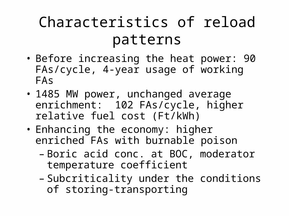
Characteristics of reload patterns
• Before increasing the heat power: 90 FAs/cycle, 4-year usage of working FAs
• 1485 MW power, unchanged average enrichment: 102 FAs/cycle, higher relative fuel cost (Ft/kWh)
• Enhancing the economy: higher enriched FAs with burnable poison – Boric acid conc. at BOC, moderator
temperature coefficient– Subcriticality under the conditions of
storing-transporting

Opportunities for fuel development
• Present or modified geometry • Enrichment ( 4.2 – 4.4)• Annual number of FAs, 4 or 5-year
usage of FAS, maximum burnup • Pins with Gd-burnable poison
(number, arrangement)• CFA follower (with burnable
poison ?)
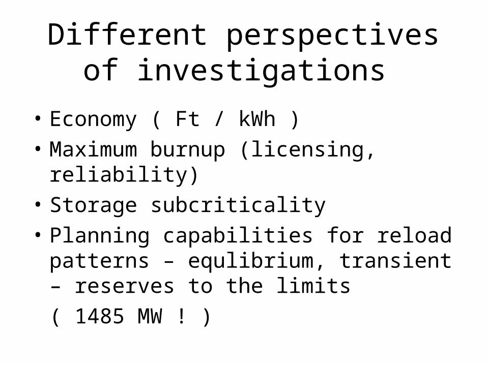
Different perspectives of investigations
• Economy ( Ft / kWh )• Maximum burnup (licensing,
reliability)• Storage subcriticality • Planning capabilities for reload
patterns – equlibrium, transient – reserves to the limits ( 1485 MW ! )
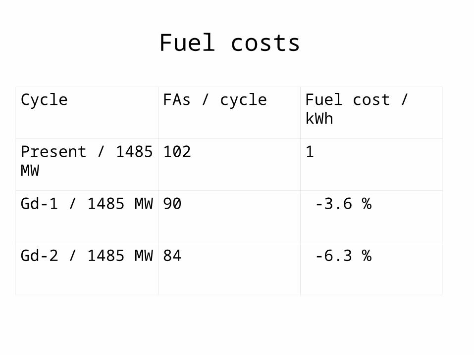
Fuel costs
Cycle FAs / cycle Fuel cost / kWh
Present / 1485 MW
102 1
Gd-1 / 1485 MW 90 -3.6 %
Gd-2 / 1485 MW 84 -6.3 %
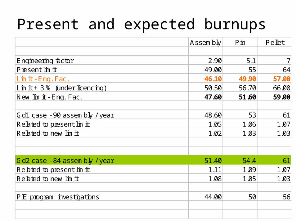
Present and expected burnups Assembly Pin Pellet
Engineering factor 2.90 5.1 7Present limit 49.00 55 64Limit - Eng. Fac. 46.10 49.90 57.00Limit + 3 % (under licencing) 50.50 56.70 66.00New limit - Eng. Fac. 47.60 51.60 59.00
Gd1 case - 90 assembly / year 48.60 53 61Related to present limit 1.05 1.06 1.07Related to new limit 1.02 1.03 1.03
Gd2 case - 84 assembly / year 51.40 54.4 61Related to present limit 1.11 1.09 1.07Related to new limit 1.08 1.05 1.03
PIE program investigations 44.00 50 56

Higher enriched fuel (3 Gd pins)
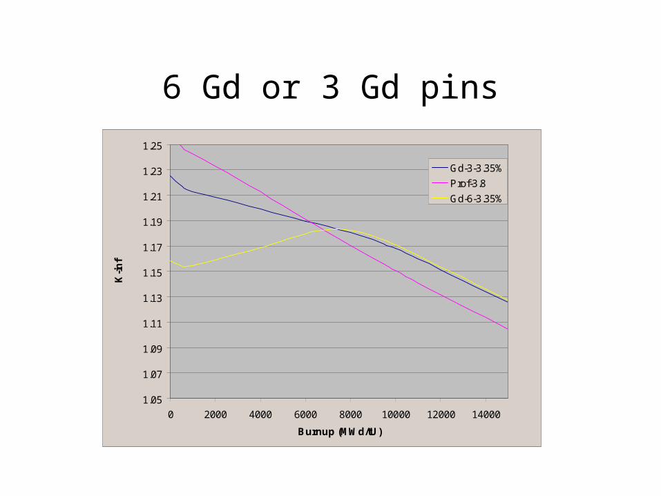
6 Gd or 3 Gd pins
1.05
1.07
1.09
1.11
1.13
1.15
1.17
1.19
1.21
1.23
1.25
0 2000 4000 6000 8000 10000 12000 14000
Burnup (MWd/tU)
K-i
nf
Gd-3-3.35%
Prof-3.8
Gd-6-3.35%

Limits during the cycle (examples)Cycle Data Calculated by C-PORCA Unit=5 Cycle=7
Pin.p_max [kW]
teff [FPD]320300280260240220200180160140120100806040200
Pin.
p_m
ax [
kW]
50
49
48
47
Cycle Data Calculated by C-PORCA Unit=5 Cycle=7
t_sub_max [C]
teff [FPD]300250200150100500
t_su
b_m
ax [
C]
322
321
320
319
318
317
316
315
Cycle Data Calculated by C-PORCA Unit=5 Cycle=7
Pin.p_max [kW]
teff [FPD]350300250200150100500
Pin.
p_m
ax [
kW]
48
47
46
45
44
Cycle Data Calculated by C-PORCA Unit=5 Cycle=7
t_sub_max [C]
teff [FPD]350300250200150100500
t_su
b_m
ax [
C]
321
320
319
318
317
316
315
314
313
6 Gd pins
6 Gd pins
3 Gd pins
3 Gd pins

Storage subcriticality
• 6 Gd pins: deep subcriticality for all cases
• 3 Gd pins : Gd-1 o.k., Gd-2
• New calculations: – Modified geometry with 3 Gd-pins:
o.k.

Ultimate common proposal/ 1
- Diameter of fuel pin - 9,07 mm; - Height of fuel pin in the working FA - 2480 mm;- Height of fuel pin in the working control FA - 2360 mm;- Outer diameter of fuel pellet - 7,6 mm;- Inner diameter of fuel pellet - 1,20 mm;- Lattice pitch of fuel pins - 12,3 mm;- Thickness of the shroud of working and control FAs - 1,5 mm;- Outer „diameter” of working and control FAs - 145 mm;- Average enrichment of working and control FAs kb 4,25 %;

Ultimate proposal / 2

Higher enriched fuel (Russian proposal)

Features of equilibrium cycle/1
FUEL DESCRIPTION 1ST C. 2ND C. 3RD C. 4TH C. 5TH C.
3-gd pins working FA 72 12.06 78 25.35 72 37.19 78 45.16 12 47.27
3-gd pins.Hf fol. FA 12 15.65 6 28.37 12 41.27 6 47.68 0 0.00
1.6%-os follower FA 0 0.00 1 18.91 0 0.00 0 0.00 0 0.00

Features of equilibrium cycle/2
teff power rodh6 tin flow cb apmax s po ppmax s po pin tsmax s po cha nlmax nllim nltar s po le pin
0.0 1485.0 212.0 267.0 30000.0 6.13 5.56 1 13 47.5 1 13 92 316.4 1 13 176 236.7 325.0 88.3 1 9 10 35
5.0 1485.0 212.0 267.0 30000.0 6.13 5.64 1 13 48.0 1 13 92 316.9 1 13 176 235.5 325.0 89.5 1 24 10 122
20.0 1485.0 212.0 267.0 30000.0 5.71 5.63 1 13 47.9 1 13 92 316.8 1 13 176 232.2 325.0 92.8 1 24 10 122
40.0 1485.0 212.0 267.0 30000.0 5.28 5.54 1 13 47.2 1 13 92 316.1 1 13 176 230.3 325.0 94.7 1 9 9 35
60.0 1485.0 212.0 267.0 30000.0 4.86 5.47 1 24 47.1 1 24 124 316.0 1 24 245 229.2 325.0 95.8 1 9 9 35
80.0 1485.0 212.0 267.0 30000.0 4.44 5.49 1 24 47.1 1 24 124 315.9 1 24 245 228.0 325.0 97.0 1 9 8 35
100.0 1485.0 212.0 267.0 30000.0 4.03 5.50 1 24 47.0 1 24 111 315.9 1 24 245 161.0 258.8 97.7 1 15 12 71
120.0 1485.0 212.0 267.0 30000.0 3.63 5.50 1 24 47.0 1 24 111 315.9 1 24 216 158.8 256.5 97.7 1 15 12 71
140.0 1485.0 212.0 267.0 30000.0 3.22 5.51 1 24 47.0 1 24 111 315.9 1 24 216 156.9 254.3 97.4 1 15 12 71
160.0 1485.0 212.0 267.0 30000.0 2.82 5.51 1 24 46.9 1 24 111 315.8 1 24 216 155.2 252.1 96.9 1 15 7 71
180.0 1485.0 212.0 267.0 30000.0 2.42 5.52 1 24 46.8 1 24 111 315.7 1 24 216 155.3 250.8 95.4 1 44 7 23
200.0 1485.0 212.0 267.0 30000.0 2.02 5.51 1 24 46.8 1 24 111 315.7 1 24 216 155.0 248.6 93.6 1 44 6 23
220.0 1485.0 212.0 267.0 30000.0 1.62 5.51 1 24 46.7 1 9 35 315.6 1 24 216 154.6 246.3 91.8 1 44 6 23
240.0 1485.0 212.0 267.0 30000.0 1.22 5.50 1 24 46.6 1 54 82 315.5 1 24 216 153.5 243.5 90.0 1 44 5 13
260.0 1485.0 212.0 267.0 30000.0 0.82 5.50 1 24 46.4 1 9 35 315.4 1 24 216 153.2 241.3 88.1 1 44 5 13
280.0 1485.0 212.0 267.0 30000.0 0.42 5.49 1 24 46.3 1 9 35 315.3 1 24 216 152.9 239.1 86.2 1 44 5 13
300.0 1485.0 212.0 267.0 30000.0 0.03 5.48 1 24 46.1 1 24 111 315.2 1 24 216 152.5 236.9 84.4 1 44 5 13
320.0 1485.0 225.0 267.0 30000.0-0.31 5.48 1 24 46.0 1 24 111 315.1 1 24 216 153.7 234.6 80.9 1 15 16 71
323.0 1485.0 245.0 267.0 30000.0-0.26 5.48 1 24 46.1 1 9 35 315.2 1 24 245 162.2 234.3 72.0 1 15 17 71
325.0 1485.0 245.0 267.0 30000.0-0.30 5.48 1 24 46.1 1 9 35 315.2 1 24 245 162.5 234.1 71.5 1 15 17 71

Process of works
• 2006 second half: decision making (Hungarian – Russian)
• 2006 end : contracts for the analysis (TVEL, KFKI, etc. )
• 2007 –2008: safety analyses• 2009 : 12-18 Test FAs to Paks• 2010 : FAs for the whole core (84
pieces)

One main problem: mixing in the FA-head

Test FA for hydraulical measurement

Process of solution
• Buying the measured results from TVEL
• CFD program validataion• Parametrization of temperature
difference• Introduction of its results into
VERONA system • Check on the test FAs, corrections