modification of mono-tube shock absorber
TRANSCRIPT
IJSRD - International Journal for Scientific Research & Development| Vol. 2, Issue 07, 2014 | ISSN (online): 2321-0613
All rights reserved by www.ijsrd.com 348
Modification of Mono-Tube Shock Absorber Prashant Mulik
1 E. N. Aitavade
2
2Associate Professor
1,2Department of Mechanical Engineering
1TKIET, Warananagar, Maharashtra, India
2AMGOI, Wathar, Maharashtra, India
Abstract— Ride comfort and handling of off-road vehicles
can be significantly improved by replacing the normal
passive dampers in the vehicle suspension system with
controllable Semi-active dampers. The semi-active damping
control system with variable shock absorber is widely used
to improve the vehicle dynamic characteristics such as ride
comfort and driving safety. To achieve better vehicle
performance, the shock absorber with wide range of
damping force variation develops. This is practically
achieved by external valve control by manually. The
performance of the semi-active shock absorber is
investigated by single degree freedom (quarter vehicle
model) test rig.
Keywords: Suspension, damping, damper, Shock absorber
I. INTRODUCTION
Function of the suspension system is reducing the deviation
of the vehicle body from the mean line of travel to a
minimum, and the same time, thereby giving the passengers
the best possible ride and making best use of contact with
ground via tires to provide good adhesion during cornering,
acceleration and braking.
The development of faster vehicles and also the
requirements of smoother and more comfortable rides have
led to the fitment of dampers on almost on all present day
vehicles. Shock absorbers have a significant influence on
handling performance and riding comfort. Shock absorber
plays an important role not only for comfort of the riders of
the vehicle but also in the performance and life of the
vehicle. However, no further reduction of vehicle vibration
can be expected for using the optimum values of damping
coefficient and spring stiffness for the shock absorber. Thus
it is necessary to make modification to improve the
functions of shock absorber. R. D. Eyres, A. R. Champneys, And N. A. J.
Lieven [1] outlines several possible methods of modeling a
passive hydraulic damper with a bypass tube that is opened
by a pre-compressed relief valve. Initially a simple algebraic
model is derived which is developed into a more
computationally complex model incorporating the dynamics
of the internal spring valve and fluid compressibility.
Numerical simulations indicate realistic dynamical
phenomena and suggest key design parameters.
ZHU Renxue and NIU Limin [2] outlines
traditional passive suspension cannot consider riding
comfortable and handling stability synchronously. Semi-
Active Suspension (SAS) became research hotspot for its
predominance such as simple structure, low cost and so on.
However, traditional simulation modeling of SAS appeared
very complex, especially in process of deduce full Vehicle
dynamic model.
SHI Ying and TIAN Xiangtao [3] outlines the
suspension is an important part of Connecting the body and
wheel, which achieves the elastic support between the body
and the wheels to ensure the car's traveling comfort and
handling. As the main product of today's vehicle, the passive
suspension has been gaining concerns. The paper has done a
time domain numerical simulation on the suspension of a
vehicle on the basis of suspension model of 1/4 vehicle.
Michael S. Talbott and John Starkey [4] who
presented mathematical model of a gas-charged mono-tube
racing damper.The model includes bleed orifice, piston
leakage, and shim stack flows. It also includes models of the
floating piston and the stiffness characteristics of the shim
stacks. The model is validated with experimental tests on an
Ohlins WCJ 22/6 damper and shown to be accurate. The
model is exercised to show the effects of tuning on damper
performance.
II. NATURE OF WORK
The work presented in this paper is concerned with
modification of mono-tube shock absorber, goal of this
research is to create damper model to predict accurately
damping force and offers greater variation in damping.
III. DAMPER MODEL
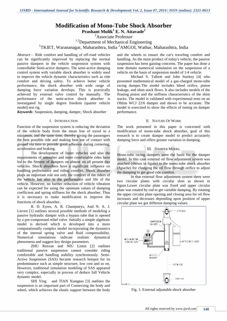
Mono-tube racing dampers were the basis for the damper
model. In this case external oil flow adjustment system was
attached (shown in figure) to the mono-tube shock absorber
(Apache) for changing the oil flow through orifice to adjust
the damping to get good ride comfort.
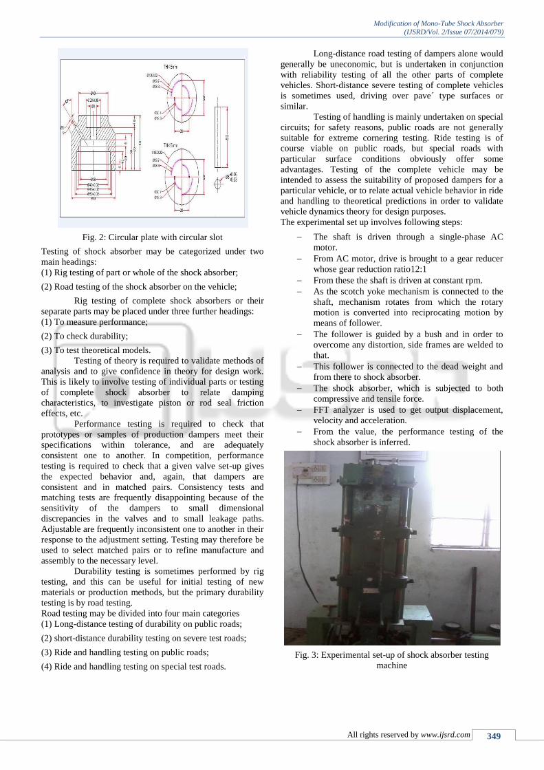
In that external flow adjustment system there were
two circular plates with circular slots as shown in
figure.Lower circular plate was fixed and upper circular
plate was rotated by rod to get variable damping. By rotating
the upper circular plate opening and closing area for oil flow
increases and decreases depending upon position of upper
circular plate we got different damping values.
Fig. 1: External adjustable shock absorber
Modification of Mono-Tube Shock Absorber
(IJSRD/Vol. 2/Issue 07/2014/079)
All rights reserved by www.ijsrd.com 349
Fig. 2: Circular plate with circular slot
Testing of shock absorber may be categorized under two
main headings:
(1) Rig testing of part or whole of the shock absorber;
(2) Road testing of the shock absorber on the vehicle;
Rig testing of complete shock absorbers or their
separate parts may be placed under three further headings:
(1) To measure performance;
(2) To check durability;
(3) To test theoretical models.
Testing of theory is required to validate methods of
analysis and to give confidence in theory for design work.
This is likely to involve testing of individual parts or testing
of complete shock absorber to relate damping
characteristics, to investigate piston or rod seal friction
effects, etc.
Performance testing is required to check that
prototypes or samples of production dampers meet their
specifications within tolerance, and are adequately
consistent one to another. In competition, performance
testing is required to check that a given valve set-up gives
the expected behavior and, again, that dampers are
consistent and in matched pairs. Consistency tests and
matching tests are frequently disappointing because of the
sensitivity of the dampers to small dimensional
discrepancies in the valves and to small leakage paths.
Adjustable are frequently inconsistent one to another in their
response to the adjustment setting. Testing may therefore be
used to select matched pairs or to refine manufacture and
assembly to the necessary level.
Durability testing is sometimes performed by rig
testing, and this can be useful for initial testing of new
materials or production methods, but the primary durability
testing is by road testing.
Road testing may be divided into four main categories
(1) Long-distance testing of durability on public roads;
(2) short-distance durability testing on severe test roads;
(3) Ride and handling testing on public roads;
(4) Ride and handling testing on special test roads.
Long-distance road testing of dampers alone would
generally be uneconomic, but is undertaken in conjunction
with reliability testing of all the other parts of complete
vehicles. Short-distance severe testing of complete vehicles
is sometimes used, driving over pave´ type surfaces or
similar.
Testing of handling is mainly undertaken on special
circuits; for safety reasons, public roads are not generally
suitable for extreme cornering testing. Ride testing is of
course viable on public roads, but special roads with
particular surface conditions obviously offer some
advantages. Testing of the complete vehicle may be
intended to assess the suitability of proposed dampers for a
particular vehicle, or to relate actual vehicle behavior in ride
and handling to theoretical predictions in order to validate
vehicle dynamics theory for design purposes.
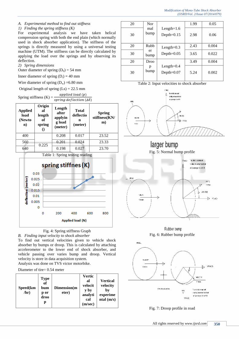
The experimental set up involves following steps:
The shaft is driven through a single-phase AC
motor.
From AC motor, drive is brought to a gear reducer
whose gear reduction ratio12:1
From these the shaft is driven at constant rpm.
As the scotch yoke mechanism is connected to the
shaft, mechanism rotates from which the rotary
motion is converted into reciprocating motion by
means of follower.
The follower is guided by a bush and in order to
overcome any distortion, side frames are welded to
that.
This follower is connected to the dead weight and
from there to shock absorber.
The shock absorber, which is subjected to both
compressive and tensile force.
FFT analyzer is used to get output displacement,
velocity and acceleration.
From the value, the performance testing of the
shock absorber is inferred.
Fig. 3: Experimental set-up of shock absorber testing
machine
Modification of Mono-Tube Shock Absorber
(IJSRD/Vol. 2/Issue 07/2014/079)
All rights reserved by www.ijsrd.com 350
A. Experimental method to find out stiffness
1) Finding the spring stiffness (K)
For experimental analysis we have taken helical
compression spring with both the end plain (which normally
used in shock absorber application). The stiffness of the
springs is directly measured by using a universal testing
machine (UTM). The stiffness can be directly calculated by
applying the load over the springs and by observing its
deflection.
2) Spring dimensions
Outer diameter of spring (D0) = 54 mm
Inner diameter of spring (Di) = 40 mm
Wire diameter of spring (Dw) =6.80 mm
Original length of spring (Ls) = 22.5 mm
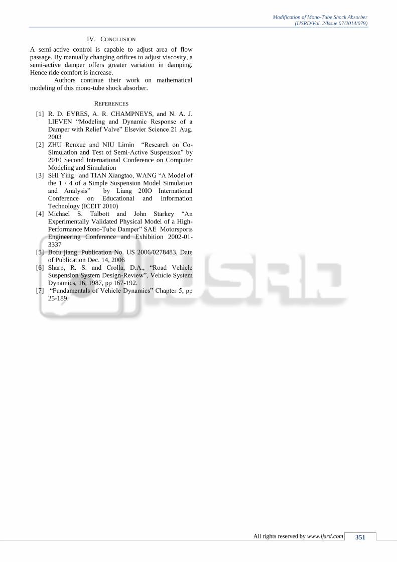
Spring stiffness (K) =
Applied
load
(Newto
n)
Origin
al
length
of
spring
()
Length
after
applyin
g load
(meter)
Total
deflectio
n
(meter)
Spring
stiffness(KN/
m)
400
0.225
0.208 0.017 23.52
560 0.201 0.024 23.33
640 0.198 0.027 23.70
Table 1: Spring testing reading
Fig. 4: Spring stiffness Graph
B. Finding input velocity to shock absorber
To find out vertical velocities given to vehicle shock
absorber by bumps or droop. This is calculated by attaching
accelerometer to the lower end of shock absorber, and
vehicle passing over varies bump and droop. Vertical
velocity is store in data acquisition system.
Analysis was done on TVS victor motorbike.
Diameter of tire= 0.54 meter
Speed(km
/hr)
Type
of
bum
p or
droo
p
Dimension(m
eter)
Vertic
al
velocit
y by
analyti
cal
(m/sec)
Vertical
velocity
by
experime
ntal (m/s)
20 Nor
mal
bump
Length=1.6
Depth=0.15
1.99 0.05
30 2.98 0.06
20 Rubb
er
bump
Length=0.3
Depth=0.05
2.43 0.004
30 3.65 0.022
20 Droo
p
bump
Length=0.4
Depth=0.07
3.49 0.004
30 5.24 0.002
Table 2: Input velocities to shock absorber
Fig. 5: Normal bump profile
Fig. 6: Rubber bump profile
Fig. 7: Droop profile in road
Modification of Mono-Tube Shock Absorber
(IJSRD/Vol. 2/Issue 07/2014/079)
All rights reserved by www.ijsrd.com 351
IV. CONCLUSION
A semi-active control is capable to adjust area of flow
passage. By manually changing orifices to adjust viscosity, a
semi-active damper offers greater variation in damping.
Hence ride comfort is increase.
Authors continue their work on mathematical
modeling of this mono-tube shock absorber.
REFERENCES
[1] R. D. EYRES, A. R. CHAMPNEYS, and N. A. J.
LIEVEN “Modeling and Dynamic Response of a
Damper with Relief Valve” Elsevier Science 21 Aug.
2003
[2] ZHU Renxue and NIU Limin “Research on Co-
Simulation and Test of Semi-Active Suspension” by
2010 Second International Conference on Computer
Modeling and Simulation
[3] SHI Ying and TIAN Xiangtao, WANG “A Model of
the 1 / 4 of a Simple Suspension Model Simulation
and Analysis” by Liang 20IO International
Conference on Educational and Information
Technology (ICEIT 2010)
[4] Michael S. Talbott and John Starkey “An
Experimentally Validated Physical Model of a High-
Performance Mono-Tube Damper” SAE Motorsports
Engineering Conference and Exhibition 2002-01-
3337
[5] Bofu jiang, Publication No. US 2006/0278483, Date
of Publication Dec. 14, 2006
[6] Sharp, R. S. and Crolla, D.A., “Road Vehicle
Suspension System Design-Review”, Vehicle System
Dynamics, 16, 1987, pp 167-192.
[7] “Fundamentals of Vehicle Dynamics” Chapter 5, pp
25-189.