module 6- critical speed of shafts, torsional …
TRANSCRIPT

S6ME MBITS- DYNAMICS OF MACHINERY MODULE-VI
1 | P a g e
MODULE 6- CRITICAL SPEED OF SHAFTS, TORSIONAL VIBRATIONS, MDOFS
When the rotor is mounted at midspan, the shaft at midspan deflects by a small amount ∆ such
that k∆ = mg; even then the shaft is assumed to be perfectly straight. When the shaft rotates, the
eccentricity of the rotor e causes to bend the shaft by distance s at midspan . s is called dynamic
deflection and keeps on changing until the equilibrium is reached given by:
m(s+e) ω2 = ks The value of s in this equation will be maximum and is called amplitude of
dynamic deflection
(k-m ω2)s = me ω
2 dividing by m and arranging as s/e form we get
=
=
defining r=
when r approaches 1 (ω equals ωn ), the shaft tends to blow at
violently and the corresponding rpm is called critical speed(or whirling speed or whipping speed)
Nc

S6ME MBITS- DYNAMICS OF MACHINERY MODULE-VI
2 | P a g e
Note 1: Shaft on Long bearings are equivalent to fixed end beams. To calculate the static
deflection ∆=
is used. For short bearings it is equivalent to simply
supported beams and static deflection in this case will be ∆=
Note 2: The bending moment quation is given by
. For shaft on Long bearings It is
modified and used as
For short bearings it is used as

S6ME MBITS- DYNAMICS OF MACHINERY MODULE-VI
3 | P a g e
TORSIONAL VIBRATIONS- SINGLE ROTOR SYSTEM
Consider a heavy rotor attached to the end of a light flexible shaft as shown in the figure. The
rotor receives an instantaneous torque, on removal of which executes twisting and untwisting
motion about longitudinal axis, called torsional vibrations.
The natural frequency of free torsional vibrations is given by fnA =
Hz =
Hz
Where IA is the mass moment of inertia of rotor A, LA is the distance of
the node(nodes are points of zero vibration) from Rotor A’s end. Here
node occur at fixed end. [Also IA = mA KA 2
kgm2
and J =
m
4 ]
is called the torsional stiffness which is the torque required to produce
unit twist at rotor A.
TWO ROTOR SYSTEM
In a two rotor system the two rotors receives equal and opposite momentarily torques , on
removal of which executes free torsional vibrations. As the rotors twist in opposite directions we
expect a node (zero vibration point) in between rotors A and B at a distance LA from A’s end (or
LB from B’s end). The behavioural aspect of the node is to separate the original shaft into two
separate single rotor systems fixed at one end as shown in the figures (fig c and d). Therefore
either the shaft shown in figure c or d can be used to find the frequency(using the expression for
a single rotor system) and both the frequencies should be the same as they belong to the same
parent shaft. Frequencies of the two split portions which are same will be

S6ME MBITS- DYNAMICS OF MACHINERY MODULE-VI
4 | P a g e
=
Hz which yields an important relation connecting the end rotors in a
two rotor system given by = . Thus we require either LA or LB to be found out for
evaluating the frequency as = L
or = L
where L is the total length of the parent
shaft.
THREE ROTOR SYSTEM
We expect two nodes N1 and N2 respectively in between the two opposite twisting rotors A&B
and B&C respectively. The nodes are assumed to split the shaft portions into three as shown. For
the split Figures a and c we get a single rotor system for which the below expression may be
applied.
=
Hz yields the important relation connecting the two end rotors A and C
in a three rotor system which is = . For the middle split portion and the end split portion
the expression applied is

S6ME MBITS- DYNAMICS OF MACHINERY MODULE-VI
5 | P a g e
Which yiedls the important expression connecting the Middle rotor and end rotor as:
TORSIONALLY EQUIVALENT SHAFT
If a stepped shaft of different diameters and length is given, we have to convert it into a
torsionally equivalent shaft which can be defined as a shaft of uniform diameter and length
which exhibits the same torsional behavior as that of the stepped shaft of different diameters
and lengths when equal and opposite torques are applied at the rotors.
The length L of the torsionally equivalent shaft is derives as:
If we choose to select the diameter d of the equivalent shaft as d1 , the diameter of the first step
S6ME MBITS- DYNAMICS OF MACHINERY MODULE-VI
6 | P a g e
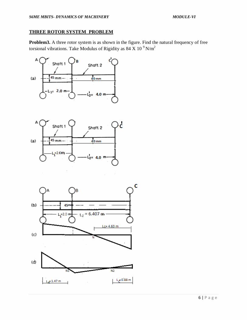
THREE ROTOR SYSTEM PROBLEM
Problem3. A three rotor system is as shown in the figure. Find the natural frequency of free
torsional vibrations. Take Modulus of Rigidity as 84 X 10 9
N/m2
S6ME MBITS- DYNAMICS OF MACHINERY MODULE-VI
7 | P a g e
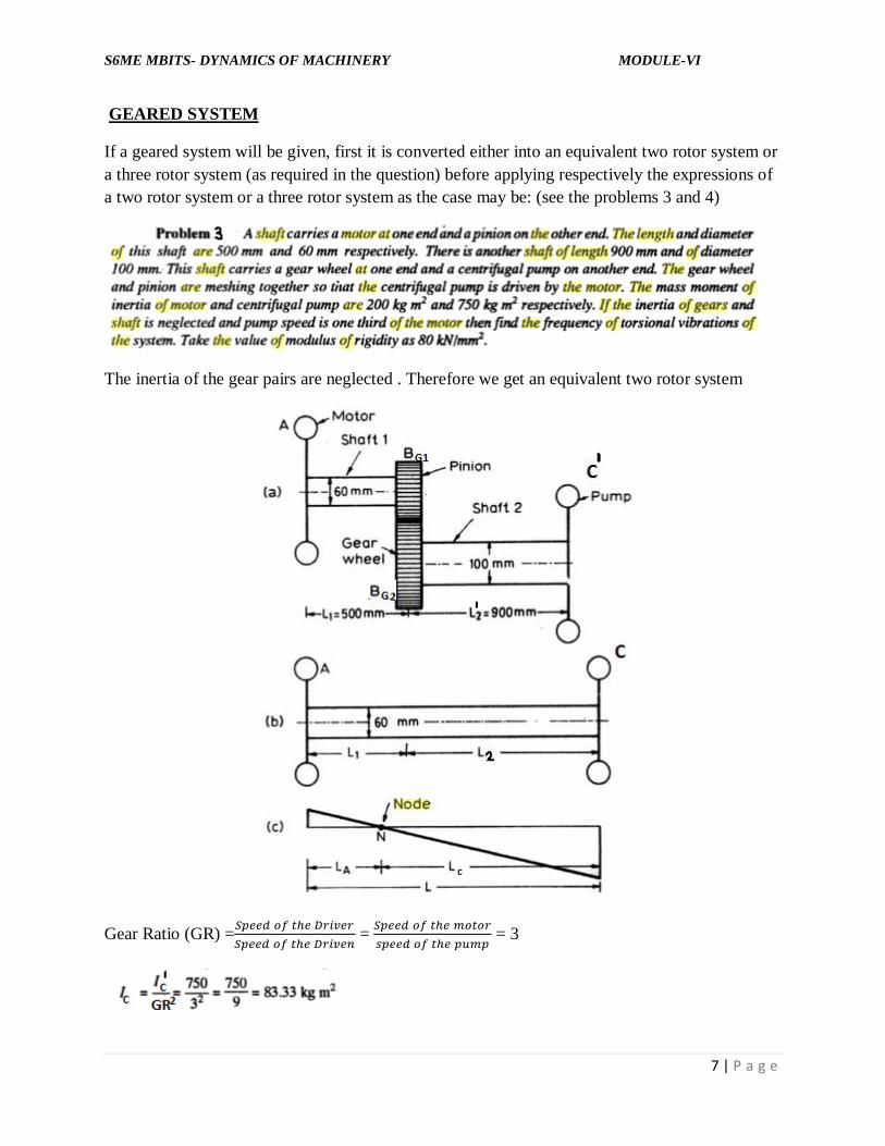
GEARED SYSTEM
If a geared system will be given, first it is converted either into an equivalent two rotor system or
a three rotor system (as required in the question) before applying respectively the expressions of
a two rotor system or a three rotor system as the case may be: (see the problems 3 and 4)
The inertia of the gear pairs are neglected . Therefore we get an equivalent two rotor system
Gear Ratio (GR) =
=
= 3

S6ME MBITS- DYNAMICS OF MACHINERY MODULE-VI
8 | P a g e
Therefore the total length L of the equivalent shaft = 1050 mm + 500 mm = 1550 mm = 1.55 m
Gear Ratio (GR) =
=
=
= 0.25
Also IB = IBG1 +
= 8 +(2/ 0.252) = 40 kg m
2
Therefore the total length L of the eq. shaft = 1.26 m

S6ME MBITS- DYNAMICS OF MACHINERY MODULE-VI
9 | P a g e
because

S6ME MBITS- DYNAMICS OF MACHINERY MODULE-VI
10 | P a g e
LC = 0.92m is not acceptable as the distance runs out of the shaft length between B and C (of
0.26 m). Therefore the acceptable length LA = 0.368m gives the single node frequency (Fig c) as
follows:

S6ME MBITS- DYNAMICS OF MACHINERY MODULE-VI
11 | P a g e

S6ME MBITS- DYNAMICS OF MACHINERY MODULE-VI
12 | P a g e

S6ME MBITS- DYNAMICS OF MACHINERY MODULE-VI
13 | P a g e
VIBRATION ABSORBERS
i) Centrifugal Pendulum Vibration Absorber
A pendulum of mass m and length L attached to the rotating body (shown as circle here) can
experience centrifugal force, as shown in the figure and therefore absorbs vibrations from the
rotating body. The pendulum oscillates with frequency proportional to the rps (N) of the rotating
body given as:
fn = N
ii) Coupled spring mass Vibration Absorber
A spring mass (k2 , m2) coupled to the original system (k1 , m1 and natural frequency ω1 =
)
absorbs vibration from the latter provided the natural frequency of the former (ω2 =
) is
equal to the the frequency of the external excitation force (ω) and the mass ratio (μ =
) is
adjusted such that
= ( 1 +
) ±
Note: If simple numerical problems, from the same topic is asked for the
exams calculate the values of frequencies and mass ratio as given above

S6ME MBITS- DYNAMICS OF MACHINERY MODULE-VI
14 | P a g e
Vibration Exciters
A vibration exciter is a machine which produces mechanical vibratory motion to provide forced
vibration to a specimen on which modal analysis and testing is to be performed. Vibration
exciters (or shakers) are helpful in the determination of dynamic characteristics of machines and
structures. They are also used in the fatigue testing of materials. Two types are discussed here:
1. Mechanical Exciters
These type of exciters makes use of unbalance created by two masses rotating at the same speed
in the opposite directions. This periodic unbalanced force(see figure) provides excitation for the
structure to be tested (which is placed on the top platform).
2. Electrodynamic shaker

S6ME MBITS- DYNAMICS OF MACHINERY MODULE-VI
15 | P a g e
In this type a current (I) passes through the coil generating a force directly proportional to the
current. If the magnetic flux intensity is B tesla the force produced by the coil in the magnetic
field is given by F=BIl where l is the length of the coil.This force accelerates the component on
the shaker table.
Vibration measuring Instruments (Seismic Instruments)-Vibrometers and Accelerometers
The seismic instrument is a device which has the functional form of mass connected through
spring and damper arrangement to the housing frame. The frame is then connected to the source
of vibration whose characteristics are to be measured. The mass tends to remain fixed in its
spatial position so that the vibrational motion is registered as a relative displacement between the
mass and the housing frame. This displacement is then sensed and indicated by an appropriate
transducer, as shown in Figure; of course, the seismic mass does not remain absolutely steady
but for selected frequency ranges it may afford a satisfactory reference position. The seismic
instrument may be used for either displacement or acceleration measurements by proper
selection of mass, spring and damper combinations. In general, a large mass and soft spring are

S6ME MBITS- DYNAMICS OF MACHINERY MODULE-VI
16 | P a g e
used for vibrational displacement measurements, while a relatively small mass and stiff spring
are used for acceleration indications.
Vibrometer (Seismometer)
A large mass and soft spring are used for vibrational displacement measurements
The governing equation is m + c + k(x-y) = 0 and the equation connecting maximum
relative displacement (between mass and support) U and the maximum displacement of support
Ys is obtained from the previous module (see the topic motion of the support)
where r =
For higher values of r (3 or above) and no damping ζ =0 , the
equation becomes
≃ 1.
That is U will be approximately Ys . That is the relative amplitude will be the amplitude of the vibrating
body and it is recorded in the displacement transducer. To retain higher values of r a large mass and soft
spring are selected (ωn =
so higher value of m and lower value of k results in lowering ωn and
therefore higher r value results in).
Accelerometer
A relatively small mass and a stiff spring (lighter in construction when compared to the above)
are used for acceleration indications. That is r will be practically very small and ζ =0, the
equation becomes
or U= =
]
2
=[Ys ω2 x constant] means constant times acceleration (acceleration= Ys ω
2). So measuring U
we can get acceleration directly.

S6ME MBITS- DYNAMICS OF MACHINERY MODULE-VI
17 | P a g e
Self Excited vibrations and stability analysis
Self-excited vibrations are disturbances belong to a fundamentally different class as compared to
the free or forced vibrations. In a self-excited vibration, the excitation force that sustains the
motion is created or controlled by the motion itself; when the motion stops the excitation
force disappears. In a forced vibration the sustaining excitation force exists independent of the
motion and persists even when the vibratory motion is stopped. An unbalanced disc mounted on
a flexible shaft running in two bearings executes an ordinary transverse forced vibration.
On preventing the disc transverse motion by mounting two ball bearing a and b on the shaft
adjacent to the disc as shown in Figure 11.1(a) and attaching their outer races to solid foundation,
thus preventing vibration of the disc but leaving the rotation undistributed. Since the unbalance is
still rotating, the external sinusoidal force remains. If a perfectly balanced rotor is mounted on
two fluid-film bearings as shown in Figure 11.1(b) and operating conditions are such that it is in
self excited vibration then if we try to prevent motion of rotor ends at bearings the self-excited
vibration will vanish and excitation force will dies down. Alternatively, a self-excited vibration
can be defined as a free vibration with the negative damping. A positive viscous damping
force is a force proportional to the velocity of vibration and directed opposite to it. A negative
viscous damping force is also proportional to the velocity but has the same direction as the
velocity. Instead of diminishing the amplitude of the free vibration, the negative damping
will increase them. Since the damping force, whether positive or negative, vanishes when the
motion stops. So the second definition of the self-excitation is in line with the first one. The
single-DOF rotor system equation of motion with negative damping can be written as
m - c + k y = 0. The solution of which can be written as
where ωn =
which is a vibration with exponentially increasing amplitude due to the term,
.

S6ME MBITS- DYNAMICS OF MACHINERY MODULE-VI
18 | P a g e
A system with positive damping is called to be dynamically stable (see Figure 11.2b), whereas
one with negative damping is known as dynamically unstable (Fig. 11.2a). On the similar
lines static instability (Fig. 11.2c) can be defined as a system with negative spring constant
(or more generally a negative value of one of the natural frequency square, ωn2). The
dynamically stability always preposes the static stability (Fig. 11.2d), but that the converse is not
true: a statically stable system may be dynamically unstable.
Vibration Control
Vibration control implies Control of vibrations or vibration suppression which is possible using
various passive and active methods.
Passive action is independent of the resulting vibration – Open Loop System.
Active method is dependent on the resulting vibration – Closed Loop System.
S6ME MBITS- DYNAMICS OF MACHINERY MODULE-VI
19 | P a g e
Reduction of excitation at source is done by: balancing of unbalanced inertia forces – rotors,
engines, changing the flow characteristics for flow induced vibrations, reducing friction,
avoiding vortex shedding to reduce self-excitation, reduce parameter variation for parametric
excitation etc.
Isolation of the source is done by modifying the transmission path of vibration between source
and the system to protect the system and this is done by the insertion of resilient elements –
Springs, Dampers, visco-elastic Materials, Pneumatic Suspension etc. between the source and the
system.
A large number of methods exist in system modification group including detuning, decoupling,
using additive damping treatments (constrained and unconstrained), stiffeners and massive
blocks (as foundation).
Redesign of a vibrating system involves modelling of materials - generally structural materials:
metals and alloys and viscoelastic polymers: natural and synthetic rubbers (with additive).
Steps in Vibration control
A. Identification and characterization of the source of vibration.
B. Specify the level to which the vibration should be reduced.
C. Select the method appropriate for realizing the vibration reduction level identified in step
B.
D. Prepare an analytical design based on the method chosen in step C.
E. Realize in practice (i.e. hardware mechanization of) the analytical design constructed in
step D.
*Vibration Isolation (and transmissibility) are included in Module V notes