module 7 introduction to basic standard knowledge for … course module/module 7a.pdf · module 7....
TRANSCRIPT

PANAMA MARITIME AUTHORITYInternational Representative Office
New York, USA
MODULE 7
Introduction to basic standard knowledge for ASI Inspectors

INTRODUCTION•
This module is distributed with the sole purpose to provide basic standard ship knowledge to all ASI inspectors.
•
This material is intended for internal use of the Panama Maritime Authority only.
•
Panama Maritime Authority shall not be held liable from the unauthorized and illegal distribution, commercialization or modification from the original version and contents of this module.

Chapter 11-
Engine Room1.
Propulsion
The ship's propulsion is normally done by propellers and in most cases by only one. That propeller is rotated via a shafting system usually driven by a diesel engine. Again in most
cases the propeller is fixed pitch, i.e. a so-called monobloc
casting. The shafting consists of the propeller’s shaft or tail shaft and at least one intermediate shaft. The propeller normally is cast bronze (copper-nickel-aluminium
bronze), the shafting is of forged steel.
As a consequence of the application of a fixed-pitch propeller, the main engine is normally a directly reversible diesel engine. A reversing gear-box is only found in combination with small engines.Systems with more than one propeller are found on fast ships, such as passenger ships and ships which are restricted by draught, or where the total power needed is too much for one propeller.The following is a description of a normal engine room of an average cargo ship.In most ships the engine room is installed aft and is compressed
to a minimum length, to leave as much length as possible for cargo, and to make the ship no longer than necessary. However, in the finer built hulls, such as the larger container ships, the engine room is located more forward, say one third from aft. Modern passenger ships and Ro-Ro vessels have their engine room spread over a large part of the ship's length, limited in height, to create a minimum loss of vertical space where cabins or vehicles can be located.In the engine room the various components for the propulsion and
power generation are located: main engine(s), generators, salt and fresh water cooling water system, lubricating oil system, starting air system, fuel system, exhaust, working air system, and all kinds of auxiliary systems like bilge and ballast systems, freshwater system, etc. Air conditioning is normally fitted in a separate room, with the refrigeration system. In the engine room various storage tanks are found, for lubricating oil, clean fuel oil, etc.A ship's engine room is complex, complete and compact.An engine room of an average cargo
ship normally contains one main engine.
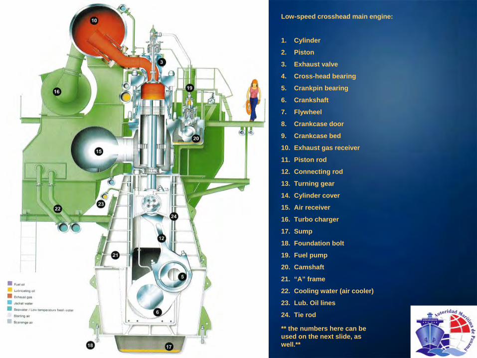
Low-speed crosshead main engine:
1.
Cylinder
2.
Piston
3.
Exhaust valve
4.
Cross-head bearing
5.
Crankpin bearing
6.
Crankshaft
7.
Flywheel
8.
Crankcase door
9.
Crankcase bed
10.
Exhaust gas receiver
11.
Piston rod
12.
Connecting rod
13.
Turning gear
14.
Cylinder cover
15.
Air receiver
16.
Turbo charger
17.
Sump
18.
Foundation bolt
19.
Fuel pump
20.
Camshaft
21.
“A”
frame
22.
Cooling water (air cooler)
23.
Lub. Oil lines
24.
Tie rod
** the numbers here can be used on the next slide, as well.**

Low speed crosshead main engine typically used on tankers and/or bulkcarriers
**description to numbers is given on the slide before this one**

1.2 Engine types
Propulsion diesel engines can be divided into three groups:
-High speed diesel engines, RPM above 960.
-Medium speed four stroke diesel engines, RPM ranging 240-960.
-Low speed engine (crosshead) two stroke diesel engines, RPM range below 240.
The fast running and medium speed engines drive the propeller after being reduced in RPM in a reduction gearbox. The fast running engines are found in small ships, such as harbor tugboats, and ships for inland navigation.Medium speed engines are found in the various middle size ships and seagoing tugs, or in ships where the height of the engine room is limited, such as Ro-Ro ships. This engine also drives the propeller after being reduced in RPMThe slow running engine is directly coupled to the propeller and
is normally installed in ships ever 30,000 dwt.
1.3 Fuel
The criterion for the choice between the engine types, apart from the size of the ship, the available space and the required power, is the fuel which can be used. Diesel oil (MDO) is best, produces least dirt, but is expensive. The so called heavy fuel (HFO) is much cheaper, but requires additional systems as pre-cleaning and heating. It produces sludge and dirtier exhaust gases. It contains more sulphur
than diesel oil. This heavy fuel can only be used in medium and
slow speed engines. High speed engines require high quality diesel oil.
Fuel System
Purifier
Fuel pumps

1.
Crankshaft with counter weights
2.
Connecting rod
3.
Stepped piston
4.
Cylinder liner
5.
Fire ring with jet cooling
6.
Cylinder head
7.
Individual cylinder jacket8.
Cylinder crankcase
9.
Crankshaft bearing cover
10.
Lateral crankshaft bearing bolt
11.
Crankshaft bearing bolt
12.
Cylinder head bolt
13.
Camshaft fuel injection
14.
Fuel pump15.
Fuel injection pipe
16.
Push rod
17.
Camshaft valve control
18.
Rocker arm
19.
Exhaust valve with propeller
20.
Inlet valve
21.
Starting valve
22.
Injection nozzle
23.
Charging air pipe
24.
Exhaust gas pipe
25.
Cooling water pipes
26.
Charging air cooler
27.
Exhaust gas turbo charger
28.
Adjusting device for injection time
29.
Adjusting device for valve timing
30.
Governor actuator
Medium speed V-engine
15
14

The heavy fuel has a higher viscosity and cannot be pressed through injectors without treatment. It needs heating to decrease the viscosity and purifying to eliminate water and dirt
particles, too big to pass the injectors. Heating is done in fuel heaters, mostly by electric heating. The cleaning is done in separators, centrifuges where water and the heavy particles are separated from the oil.
The fuel is stored on board in tanks, the bunkers. In cargo ships often in the double bottom tanks. Fuel is supplied normally by a bunker boat through.a
hose, straight into the ship's tanks. From the tanks it is pumped to a smaller tank in the engine room, the settling tank, a high, vertical tank, where
water and heavy dirt sinks down, and via a
high suction, the oil is pumped through the separators to the sludge tank, the clean oil tank. The water and dirt go straight to the sludge tank. From the clean oil tank the fuel is pumped by the low pressure fuel pump to the high pressure (HP) fuel pump which pumps it to the injectors. There is one HP pump per cylinder. Surplus oil, depending on the demand of the engine, flows back to the day tank.
The dirt from the separators goes to the sludge tank, to be disposed ashore or by an incinerator.
The newer diesel engines have a so called common rail fuel system. A high pressure fuel pump keeps a piece of pipe at the injection pressure, and between that pipe and the injectors an electrically opened and closed valve is installed. Opening and closing is regulated through a computer, giving far more possibilities in fuel quantity and timing, per cylinder, and adjustable during operation.
1.4 CoolingAll diesel engines produce heat and need cooling. This can be achieved by air cooling, but more common is liquid (water) cooling. This can be done directly when the outboard cooling water is pumped in, and via a filter passes the engine and is again pumped overboard. This is used in very small ships only, and also only when the ship is always in fresh water.
The bigger ships use a closed circuit cooling system with water containing inhibitors, to protect the diesel engine against corrosion. The cooling liquid is then cooled in a heat exchanger
outside the diesel engine. The cooling medium is again seawater passing a filter and a heat exchanger, and finally pumped overboard. A separate seawater pump is then required. In small ships the heat exchanger can be installed in a sea chest which has natural circulation for seawater. That saves out another pump.
Cooler, Pump, and often also the filter are installed double, with the necessary valves, to enable maintenance and cleaning during operation.

1.5 Lubrication
Each diesel engine needs lubrication. Normally this is done by pumping oil through the bearings and forcing this upwards from the crankcase towards the cylinder liners. Small engines have a built-in oil pump, larger engines have external pumps.
Oil is pumped through a filter into the engine. All the main bearings have their separate supply pipes. After use, the oil drips down into the crankcase, from where it falls into the main
engine sump tank below the engine. From that tank it
is pumped via an oil cooler and a filter system to the engine again. The quality of the filtering is critical for the engine's service life. The filter system can be complex. In a small engine it is only a filter, to be exchanged every so many hours. In big ships the oil is pumped through a very complicated micro-filter which has built-in self-cleaning system via back-
flushing. There are two parallel filters to avoid stopping the engine during filter change. The lubricating oil pump is mostly a
screw or gear type pump, where the output and pressure is constant, contrary to a centrifugal pump. Lubrication in large engines is much more complicated. The lubricating oil also has a
cooling function, particularly for the pistons.
In large engines, with a crosshead, these systems can he divided into crankcase lubrication, cylinder lubrication and cylinder oil cooling.
Cylinder Lubrication
Cylinder lubricators

1.6 Starting
Small engines are started using an electrically driven starting motor on batteries. The larger engines; however, are started using compressed air, released in the cylinders, through the starting air valves on the cylinder heads, in the same sequence as the combustion sequence. The main air line from air vessel to engine contains a distributor, a rotating disc, driven by the engine crankshaft, with holes, leading air through
to the appropriate cylinder.
When the engine is turning, fuel is injected, and the air injection can be stopped. The compressed air is held in compressed air vessels, and kept under pressure and refilled by air compressors. The required pressure is approximately 25 bar.
Starting air receivers Starting air vessel stop valveStarting air compressors
1.7 Exhaust gasThe combustion produces exhaust gas. This is a very hot mix of carbon dioxide, nitrogen oxides, unburned fuel, surplus oxygen, sulphur
dioxide, and carbon (soot). The sulphur
oxides are harmful. With water they form acids, corrosive to the steel exhaust pipes, and not environmentally friendly. This of course also counts for carbon dioxide, and the nitrogen oxides. Pressure is put on reduction of N0x and S0x.The heat in the exhaust gas can be used to warm up fuel, and for
other purposes, such as accommodation heating. in the exhaust gas pipe a heat exchanger can be built-in through which water or another liquid is pumped. When the liquid is water, and it evaporates, the heat exchanger is called an exhaust gas boiler. When it does not evaporate, the heater is called an exhaust gas economizer.

1.
Exhaust gas inlet
2.
Exhaust gas turbine
3.
Air inlet filter
4.
Rotary compressor
5.
Compressed air outlet
1.8 Combustion airThe air needed in the cylinders for combustion, is normally drawn from the engine room. In small ships only an opening to atmosphere is sufficient, in big ships electrically driven ventilators supply the engine room with a large quantity of air,
also to keep the engine room temperature sufficiently low. The performance of the engine can be boosted by supplying the cylinder with air of a higher pressure. More air means more fuel
that can be burned. And that again means more engine output.The output of the engine is limited by the temperature of the exhaust gas. When the temperature in the cylinder becomes too high, damage can occur to outlet valves, cylinders etc. Therefore the air must have a certain over-capacity for cooling purposes.The quantity of air can be boosted further by compressing the air before it goes into the cylinder. The air can be compressed by using the velocity of the
exhaust gas. In the exhaust gas line a turbine is fitted, driving a rotary compressor. The air rises in temperature due to the compression. By cooling this air after compression, the density increases and even more air can be supplied to the cylinder.Cooling water from the main system is used for this air cooling,
and also to cool the whole unit.
1.9 ShaftingThe shafting arrangement transfers the torque produced by the engine to the propeller. In the most common, most simple and most reliable systems this is a monobloc
casting. Controllable pitch propellers are also quite common, but more complex, expensive and more vulnerable to failures. They have; however, the advantage of the optimal pitch you need for each speed and a constant RPM, which gives the possibility of a main engine driven (shaft) generator.Normally the shafting consists of one intermediate shaft and the
tail shaft. The Intermediate shaft is needed to create access for when the tail shaft needs to be withdrawn. The intermediate shaft is then to be laid aside. In the system are a number of bearings: one or two bearings on the intermediate shaft, and the bearings in the stern bush. The total number can vary depending on the length of the system and the weight of
the shafts.The after most shaft, the tail shaft, is supported by the stern bearing. These are located inside the afterpeak
tank, out of sight. These bearings are part of the stern tube, which is completely filled with lubricating oil so that the tail shaft rotates in
oil.

At the aft end of the stern tube a complicated sealing system is
fitted, to keep seawater outside and the a inside the stern tube. This seal is located just forward of the propeller. The outer seal is protected by a surrounding ring, the rope-guard. At the forward end of the stern tube, where the shaft leaves the engine room a similar, but less complicated seal is fitted, again to retain the oil in the stem tube and not leaking it into the engine room.The propeller is fitted on the tail shaft, normally with a press-on fit.The after end of the tail shaft is conical, fitting precisely in the conical hole of the propeller. Sometimes it is secured against turning by a key. But
this is old fashioned. The normal way nowadays is the so-called keyless fitting, where the propeller is pressed by high oil pressure on the conical surface
during the push-up.A controllable pitch propeller (CPP) is fitted with bolts on a flange at the after end of the tail shaft. Such a shaft has to he withdrawn outwards, which
often makes removal of the rudder necessary. The shafting of a CPP is much more
complex, due to the hydraulic functions needed by the propeller, and which are distributed through hollow shafting.A fixed-pitch propeller is normally a right handed propeller. A controllable pitch propeller is left handed, this to create astern
properties similar to those of a fixed-
pitch propeller.
Shafting looking aft
Main engine flywheel with intermediate shaft and main lubricating oil pumps driven by an electric motors
Gearboxes and CouplingsBetween diesel engine and propeller, depending on the RPM of the
diesel and the desired RPM of the propeller, often reduction gearing is needed.
This is usually a steel box, situated behind the diesel engine(s), with incoming driveshaft(s), each provided with teeth, which drive a larger wheel, which is connected to the intermediate shaft. The gearbox is partly filled with oil, and an internal pumpsprays oil over the teeth. The gears can have various shapes. Straight teeth, teeth under an angle or
helical gears. The helical gears are often chosen for noise and vibration reasons, but are the most expensive type. When a shaft generator is part of the installation, the gearbox is provided with a power-take-off (PTO). Depending on the number of incoming and outgoing shafts, a gearbox can have
various configurations.Between shafts and generators, couplings are needed. When two main engines are used, one can be taken from the system for maintenance or, when also a shaft generator is used, only to generate power for that generator.The
shaft generator then also has a coupling.For torsion-vibration reasons, flexible elements are needed. These can be separate, but also incorporated into the coupling.

1.10 Electricity
A ship has a considerable electrical power consumption. Steering
gear, lighting, ventilation, all the pumps, compressors, air conditioning, etc. Diesel generators supply the power.At least two diesel generators are needed. When one fails, the other can take over. To allow proper maintenance of one diesel generator when the ship is in normal operation, and not to be at risk of insufficient redundancy, a third diesel generator is normal. All three are identical, and each is capable of taking the complete
electrical power demand at sea.The electricity produced is normally 3-phase current. When more than one generator is running the electric output can be connected through a circuit breaker to the bus-bars of the main switchboard in so called parallel mode. A synchronizer panel is installed in the switchboard, which only allows the circuit breaker to be closed when the generator which is to be switched on, is in phase with the other already running generator(s). Together they then feed one system. The diesel output power is controlled by a governor on each diesel engine that regulates the fuel quantity, while keeping the RPM constant. Big ships usually have generators that produce 440 volt and 60 Hertz (3-phase).A shaft-driven generator or PTO generator (PTO means power-take-off) is becoming popular, mostly in combination with a controllable pitch propeller, to answer the requirement of the constant RPM. The main engine produces the rotating energy, burning cheap heavy fuel instead of expensive diesel oil. Parallel running between the diesel generators and the shaft generator is normally only possible for a short period i.e. the time to take over the load.To ensure electric power for essential functions (navigation lights, steering gear, bridge equipment, lighting in engine room and accommodation, etc.) in case of a total electric power failure, a so-called blackout„
ships are equipped with an emergency generator. This generator feeds the emergency switchboard. It
switches on automatically when this switchboard does no longer receive power from the main switchboard.Large main engines produce so much heat in the exhaust gas that steam can be produced in an exhaust gas boiler to the extent that a steam turbine generator can supply the necessary electricity for at least the normal electricity demand at sea. A steam turbine then drives the alternator through a reduction gear box. This saves a diesel generator and the fuel for it. Such a system involves a complicated steam system, of high quality, with the necessary safety devices, a condenser, circulating pumps, cooling water pumps, feed water and condensate pumps and accurate water treatment. Electrical consumers are divided into two groups: essential and non-essential. In case of a power failure, the non-essential users are automatically switched off. Essential users such as steering
gear, main engine, lub
oil, fuel and cooling water pumps, navigation lighting and bridge equipment, are maintained operational as long as possible.

1.11 Heating
The heat produced by the engine is normally not sufficient for heating the ship, and the engine is not always running. Most ships therefore have a small oil fired boiler, for accommodation heating and fuel heating. This oil fired boiler can be combined with the exhaust gas boiler. Ordinary cargo ships can do with a small boiler. Tankers generally have large boilers as they use steam to keep their cargo pump able by heating, and often have
steam driven cargo pumps for the discharge of their cargo. In that case also the ballast pumps are steam driven.
Instead of steam, other liquids can be used for heat transfer, e.g. thermal. The advantage is that the system is simple. A disadvantage is that the oil brings
a fire hazard with it. Small boiler
1.12 Heat exchangersHeat is produced at various places. This heat must be disposed of. But on the other hand liquids or air must be heated. Therefore a number of heat exchangers are found in every engine room:-Fresh cooling water coolers:
•for cooling water-Fresh cooling water heater:
•pre-warming of diesels-Lubricating oil coolers:
•one for each auxiliary diesel engine, attached to the engine, two for the main engine-Air coolers:
•for combustion air-Air heaters:
•for general heating, air conditioning-Oil heaters:
•for fuelTypes of coolers:Straight tube coolers, U-tube coolers, Plate coolers.
1.13 PumpsLiquids are to be pumped through all the systems. For different
media different pumps are used:-For cooling water normally centrifugal pumps: low pressure, large quantity.-For lubricating oil: screw type pumps: constant supply, constant
pressure;-For boiler feed water two-
or three-stage centrifugal pumps or piston pumps;-For fire pumps; : high pressure centrifugal pumps;-For highly viscous fuels: gear type pumps; -For dirty water, etc: pumps, membrane pumps.
Centrifugal pumps

1.14 SafeguardingThe various machinery in the engine room is safeguarded by control systems. A simple diesel engine of 15 kW already has a lubricating oil pressure alarm. When the lubricating oil pressure is too low, a red light combined with a penetrating high noise will draw attention. The bigger the engine, the more safeguards. For example there are alarms for: cooling water too hot, cooling water pressure low, lub
oil level low, return lub
oil temperature too high and so forth.In a modern engine room which is arranged for controlled operation, all these alarms are brought to a control room where on screen the abnormality is shown, and remedial action can be taken. By human action, or even automatically.When cooling water is too hot for instance, the flow can be raised by opening a regulating valve. When the water temperature is too low, that same valve can reduce the flow. When that remedy fails: alarm.1.15 Vibration and noiseDiesel engines produce vibration (out of balance pulses). Each combustion inside a cylinder produces a pulse conveyed via the foundation of the diesel engine into the ship.The propeller is also a source of vibration. Firstly, the pressure field around the blades of the rotating propeller give pressure variations on the aft ship above the propeller. Secondly the blades when rotating through their cycle meet water with a different velocity at each location of that field.These actions produce pulses:-in the hull above the propeller(s)-through the shafting and its bearings.Each part of a ship has its own resonance (natural) frequency. When the pulses induced by some machinery match the resonance frequency of a ship's component, and the pulse is sufficiently strong, vibration is the result. Noise is generated
by air and structure vibration. Main sources of air pulses are the exhaust system, the combustion explosions and the turbo chargers.
Vibration sources
1.
Exhaust gas noise (on bridge wing)
2.
Airborne noise (in engine room)
3.
Structure borne noise ((in accommodation)
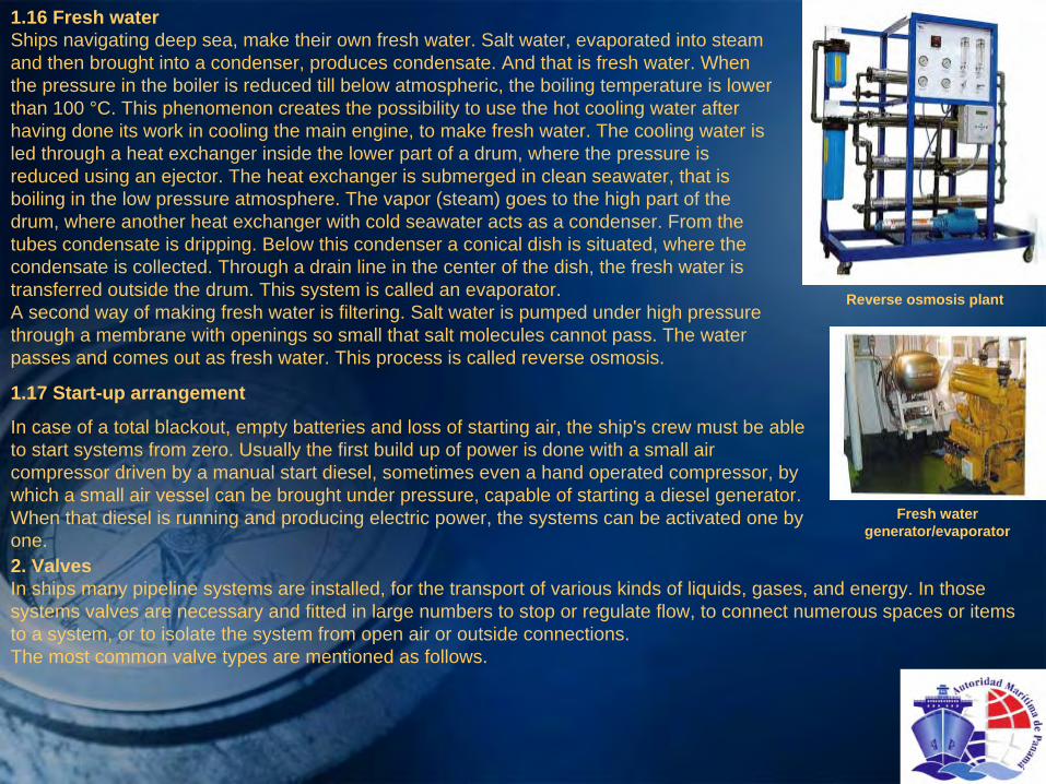
1.16 Fresh waterShips navigating deep sea, make their own fresh water. Salt water, evaporated into steam and then brought into a condenser, produces condensate. And that
is fresh water. When the pressure in the boiler is reduced till below atmospheric, the boiling temperature is lower than 100 °C. This phenomenon creates the possibility to use the hot cooling water after having done its work in cooling the main engine, to make fresh water. The cooling water is led through a heat exchanger inside the lower part of a drum, where the pressure is reduced using an ejector. The heat exchanger is submerged in clean seawater, that is boiling in the low pressure atmosphere. The vapor (steam) goes to the high part of the drum, where another heat exchanger with cold seawater acts as a condenser. From the tubes condensate is dripping. Below this condenser a conical dish is situated, where the condensate is collected. Through a drain line in the center of the dish, the fresh water is transferred outside the drum. This system is called an evaporator.A second way of making fresh water is filtering. Salt water is pumped under high pressure through a membrane with openings so small that salt molecules cannot pass. The water passes and comes out as fresh water. This process is called reverse osmosis.
Reverse osmosis plant
Fresh water generator/evaporator
1.17 Start-up arrangement
In case of a total blackout, empty batteries and loss of starting air, the ship's crew must be able to start systems from zero. Usually the first build up of power is done with a small air compressor driven by a manual start diesel, sometimes even a hand operated compressor, by which a small air vessel can be brought under pressure, capable of starting a diesel generator. When that diesel is running and producing electric power, the systems can be activated one by one.2. ValvesIn ships many pipeline systems are installed, for the transport of various kinds of liquids, gases, and energy. In those systems valves are necessary and fitted in large numbers to stop
or regulate flow, to connect numerous spaces or items to a system, or to isolate the system from open air or outside connections.The most common valve types are mentioned as follows.

2.1 Gate valvesA gate valve has a housing between two flanges where a wedge slides in and out, leaving the throughput completely open or closing the throughput completely or partly, for partial flow
restriction. The housing has sealing rings as seats for the wedge sides. The wedge also has a sealing ring at both sides, giving it double sealing.The bottom of the housing is often provided with a plug, allowing checking the tightness of the valve without opening up. Materials for housing and wedge are cast iron, cast steel or bronze. The sealing rings are often bronze. All kinds of variations are possible, depending on the type of liquid, possible galvanic action and fluid velocity.Additional strengthening is needed when used in high pressure systems. In use for: cooling water, ballast water, bilge systems, cargo (oil) systems, fire lines, foam lines, etc.Advantages:-100 per cent throughput-two sealing surfaces-short building length-tightness control in situDisadvantages:-vertical dimensions, especially when fitted with hydraulic actuator-weightAdditional strengthening is needed when used in high pressure systems. In use for: cooling water, ballast water, bilge systems, cargo (oil) systems, fire lines, foam lines, etc.
Globe Valve:
1.
Housing
2.
Separation
3.
Disc
4.
Spindle
Gate Valve:
1.
Housing
2.
Wedge
3.
Spindle
4.
Sealing rings
5.
Plug

2.2 Globe valve
A globe Valve has a ball shaped housing between two flanges, with a horizontal separation at half height, so configured that upper and lower part are open towards one flange each. In the separation is a circular hole, which can be closed with a disc, which is moved up and down with a threaded spindle. When
the disc is kept loose from the spindle, the globe valve sets as a non-return valve. Materials for housing and cover are cast iron, bronze, stainless steel, etc. Disc and seat may be of bronze or stainless steel. This depends on the type of liquid pumped.Advantage:-easy maintenance-easily adjustable flow-non-return possibilityDisadvantages-restricted flow, turbulence-remote control only manually (extended spindle) In use for: cooling water, steam, various clean water systems.
2.3 Butterfly valve
A butterfly valve has a ring shaped body, with the diameter of the pipeline that it is used for. In the ring, there is a circular disc, which can be turned by a spindle. The ring is clamped between the flanges of the adjacent pipelines. The ring is provided with a rubber lining on the inside, forming a seat for the disc. In open position, the flew is hardly restricted: the disc is positioned in the direction of the flow. By turning the disc 90°
or nearly 90°, the disc is closing against the rubber lining of the ring. The
rubber lining can be vulcanized, or interchangeable. There are also types with a removable seat. Materials: ring of cast steel or cast iron, disc of bronze, rubber lining of neoprene (oil resistant). Also fabricated with flanges on ring.Advantages:
Disadvantages-extremely short building length
-difficult flow regulation-Light-nearly unrestricted flow-simple actuator (only 90" movement)In use for: cooling water systems, sea water valves (overboard),
cargo systems in VLCCs
and ULCCs.
1.
Ring
2.
Disc
3.
Handle
Butterfly valve with a 1000 mm diameter:

2.4 Ball valveA ball valve has a ball shaped housing between two flanges. At half length is a dividing flange. Inside the housing is a seat ring for both flanges. A ball is fitted between the seats, with a tubular hole in the centre. Stem upwards, for rotation of ball, max. 90º. The flow is regulated by partial rotation of ball. Materials depending on use. The ball is mostly stainless steel. In use mainly for chemicals.Advantages:-double seal-unrestricted flow when completely open, no turbulence.Disadvantages:-Expensive-Heavy-difficult adjustment of both seals.Apart from the above valve types there are numerous variations on the main types:-Needle valves for accurate flow regulation are a variation of a globe valve.-Spring-loaded valves are valves which can be closed by a spring, remote
triggered. They are often basically a globe valve.-Safety
valves which open at a pressure higher than desired against a spring, are also often-Globe valves.-Spade valves are gate valves with a flat closing spade.-Non-return valves exist in numerous types:
•swing check valves in the discharge of a cargo pump,•globe valves with loose disc in cooling systems,•weight loaded swing check•valves in insert gas systems, etc.
Ball valve3. Bilge-line arrangementTo keep the engine room dry, there are so called bilge pumps. There are normally three systems. A small
pump capable of dealing with the normal small daily quantities. This small pump pumps the dirty water (water and oil) into a bilge holding tank.From that tank the water is pumped by another small pump through
a bilge water separator overboard, only when it is sufficiently clean. If not, it goes to another storage tank, the sludge tank. A second bigger pump, can pump the bilge water from the engine room straight overboard, but this is only allowed in emergencies.

A third
possibility is to use the direct suction of the main cooling water pumps. This huge capacity is for big leaks in emergencies.The bilge line arrangement is an important safety system that is
required by law.The purpose of the bilge line arrangement is to pump unwanted water which has entered the ship, out of the ship.Rules made up by governments and Classification Societies have to comply with international SOLAS rules. SOLAS states that the bilge line arrangement, the ballast line arrangement and the fire fighting arrangement must be three independent systems that can take over the work of the other systems if necessary.Small amounts of water can accumulate in the ship as a result of
condensation, leakages of pipes, results from washing, or rain, especially in "open ships".Condensation can occur when warm air hits a cold surface. In the
most favorable circumstances the water flows down the sides into the bilge well and from there it can be pumped overboard. When the water remains on (relatively cold) cargo or seeps into the cargo, damage to the cargo may occur.Ships without hatch covers, so called "open ships" have to have additional pump capacity in the bilge line arrangement to remove incoming sea water or rain.As soon as the holds are emptied and cleaned, the bilge line arrangement has to be tested. When it has been found in order, this is noted in the ship's journal. For some kinds of dangerous goods, the bilge arrangement has to have the capability to pump bilge water from any individual cargo hold. The dangerous goods have to be kept separated. Certification takes care of what kind of dangerous goods may
be transported by a ship.The valve in the bilge well (in the engine room) must be fitted with a safety device to ensure that dangerous goods cannot accidentally pass into the environment or inside the ship.To determine the amount of fluid inside a bilge well or a ballast tank two systems have to be present:-Manual. Sounding with sounding tape using a sounding pipe that ends in a tank or a bilge well to measure the height of the fluid.-With a remote measuring system. The fluid level can be read from
an indicator in the engine room (remote control). A float is placed in the bilge well and when the fluid level rises, so does the float. When the float reaches a certain level, an alarm is activated.As soon as the alarm in the bilge well is activated, the bilge alarm on the alarm panel in the engine room is activated as well. With an unmanned engine room the engineer on watch is alerted. The water levels in ballast tanks often are measured using bubble pipes. The pressure needed to blow air to the bottom, against the water pressure, is the level, picked up by a transmitter. The signal is displayed in the cargo
control room.

The bilge line arrangement consists of the following parts:
3.1 Bilge pumpsThese pumps have to be available for immediate use. However, they may also be used for other purposes according to the regulations.A bilge pump must be self-priming. This means that they do not need help (filling with water) to draw water from the intended compartment.3.2 Mountings (fittings)In shipping mountings mean ordinary valves, safety valves, plugs, filters, distributors etc. Several suction lines are mounted on a manifold. The suction lines are fitted with valves to open or close the lines. To keep the capacity as high as possible, one valve at a time should be opened. When more valves
are opened at the same time, the suction capacity in the well is reduced. Check valves are used as non-return valves.3.3 Main Bilge LineThe main bilge line is situated in the engine room and runs from
the manifold to the suction side of the pumps. The suction lines run from the manifold to the compartments that are connected. The main bilge line is usually made of galvanized steel. The bilge arrangement in the engine room consists of one (compulsory) direct system and one indirect system. The indirect system operates through a manifold.3.4 Suctions linesThe cargo holds are provided with 4 bilge wells, one in each corner of the hold. They are each provided with their own suction line to the main line. In which well the water is collected depends on list and trim.3.5 Bilge wellA bilge well has two compartments, separated by a bulkhead that extends
to half or three quarters of the height of the well. A lid with small holes covers the well. As soon as the water reaches a certain height, it will flow to the welt next to it. The suction part of the bilge line is situated in that part of the well.This suction side of the main cooling water pumps have a free suction. In case of major leak, this enables the large capacity of the cooling water pump to be used as an emergency bilge pump. This is called the emergency suction. The valve is manually operated, with a large diameter red band-wheel above the floor plates.
Two types of non-return valves
1.
Hinge point
2.
Direction of flow
3.
Closed valve (dotted lines: open valve)

3.6 Ejector
An ejector creates a vacuum by the speed of the water flowing through it. This is also a possibility for pumping bilges, for instance in chain-lockers. The pressure of the water flowing through the ejector is created by the fire fighting pump, which can build a higher pressure than the bilge and ballast pumps. The bilge water goes overboard together with the driving water.
3.7 Bilge water cleaner/separator
According to the MARPOL Convention, bilge water from the engine room cannot be pumped overboard. Any oil remaining water, has to go through a separator to separate the oil from the water. The water can, under certain circumstances, be pumped overboard. The oil goes to a dirty oil tank. This separator, with an oil-content-meter and alarm, is compulsory for ships of more than 1000 GT. The
water that is pumped overboard may not exceed 15 ppm
oil (parts per million).
4. The ballast arrangementThe ballast system is used to pump seawater (weight) in or out of the ballast tanks. The rules for the ballast system are less stringent than the rules for bilge systems.Reasons for taking ballast on board or shifting ballast once it is on board are:-To improve the stability of the ship, especially when the ship does not carry cargo,-To get the ship deeper in the water, to improve sea-keeping.-To alter
the trim-To reduce bending moments or shear farces-To control the list during loading and discharging. Many ships use an anti-heeling system for this purpose.-To improve the maneuverability.An anti-heeling system is used to minimize the list (in port). Pumps with a large capacity (1000 m3/hour) are installed between two tanks (one on port side and one on starboard side). These pumps can transfer water from one tank to the other at great speed. The system is fully automatic and much used on ships with cranes, container vessels and Ro-Ro vessels to reduce the list that can occur during cargo handling.Fore and aft peak tanks, deep tanks, double bottom tanks, and wing tanks are usually used for ballast water. All depending on the ship's type. Bulk carriers often use one of the
holds for ballast, during a ballast voyage.

An advantage of using ballast instead of fuel in the double bottom is that welding is allowed on the tanktop.The designer determines the ballast capacity to meet minimum operation draught requirements imposed by Class / IMO. The duration of the voyage and the purpose of the ship will be taken into account when deciding on the available space for ballast and the capacity of the ballast pumps.In small ships, the ballast pumps are usually suitable to act as
bilge pumps. This makes the ballast system an integrated part of the bilge arrangement, to the extent that a ballast pump
may even serve as main bilge pump.Contrary to the valves in the bilge arrangement, the valves in the ballast arrangement have to be two-way valves as the tanks must be able to be filled and emptied. Double bottom tanks, and to a lesser extent in multi-purpose ships the wing tanks can be filled directly from outside through the sea inlet,
without using the pump. Nowadays the ballast system is often designed as a ring line. Remote controlled valves are used
to empty or fill the ballast tanks.Ballast lines inside the double bottom may be made of synthetics. The bulkhead passages have to be steel, for fire safety.
1.
Suction of the pump2.
Suction from the bilge well3.
Hand wheel to operate the valve4.
Stop valve
Distributor that can be fitted with non-return valves (bilge arrangement) or stop valves (ballast arrangement):
1.
Bilge well2.
Heating coils3.
Bilge line
Bilge system arrangement

5. Fire-fighting arrangement
Fire has probably caused more ship losses than grounding, collision or bad weather. A good fire fighting arrangement, conforming to legal requirements is therefore a necessity.
The fire fighting arrangement has to transport seawater to the fire hydrants. The system consists of lines, pumps, valves with couplings, hoses, nozzles and spray installations.
A minimum of three fire fighting pumps is compulsory on all ships. One of these pumps, the emergency fire-pump, must be situated outside the engine room, with a direct connection to
the deck fire line.
Between engine room and deck fire line an isolating valve must be placed, such, that in case of a fire in the engine room, the deck lines can be pressurized using the emergency fire pump.
Fire fighting arrangement:
1.
Arrangement in the engine room
2.
Arrangement on deck
3.
Filter
4.
Isolating valve
5.
Hydrant
6.
Supply from general service pump
7.
Main fire pump
8.
Suction
9.
Emergency fire pump
10.
Sea valve

2
1.
Bilge arrangement (yellow)2.
Ballast arrangement (blue)3.
Overboard (for bilge and ballast)4.
Engine room bulkhead5.
Main bilge line, from distributor to ejector and overboard
6.
Engine room bilge line, port side, starboard side, midship
and aft All fitted to the main bilge line.
7.
Direct bilge arrangement from the engine room
8.
Suction distributor chest9.
Ejector
Bilge and Ballast arrangement on container feeder

Chapter 12 –
Propulsion & Steering Gear1.
Ship resistanceThe power required to move a ship through the water depends on the propulsive efficiency and on the total resistance of the ship. The resistance is a complex function of displacement, shape and speed.The various components of resistance can be divided as follows:a. Frictional resistanceThe friction between the water and the ship's shell is the cause
of this type of resistance. The water in the boundary layer is accelerated by the ship's speed, dragged by the molecular friction. This boundary layer is thicker, and the resistance higher when the shell is fouled.The frictional resistance is the smallest directly after delivery of the ship. During the ship’s lifetime, the roughness of the hull normally increases, due to paint layers covering older paint layers, damage, corrosion, etc. This results in a gradual drop in speed and efficiency.b. Pressure (Form) resistanceThe ship's momentum pushes the water aside at the bow and as a result, the pressure of the water increases. This increase in pressure will also take place aft. The pressure will
drop where the boundary layer is released.c. Wave resistanceThis is a result of wave systems along the hull that originate from the differences in pressure.On certain ships the use of a bulb at the bow can significantly decrease the wave making resistance. The bulb generates its own wave system, which is designed to interfere negatively with the ship's wave system. The two wave systems then neutralize each other.d. Added resistance in wavesThis type of resistance is caused by the pitching, heaving and rolling of the ship.e. Air resistanceThis depends on the vertical area above the waterline, which varies with the draught. Resistance components as mentioned in 'd' and 'e' are
variable, depending on wave direction and wind direction as experienced by the ship.
ship
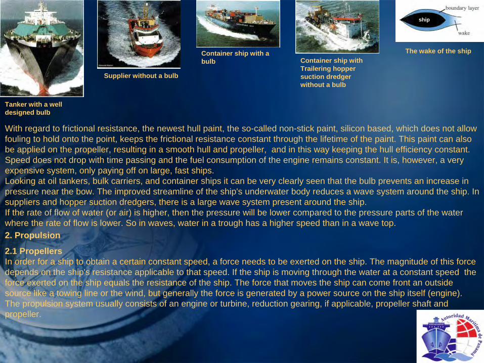
Tanker with a well designed bulb
Supplier without a bulb
Container ship with a bulb Container ship with
Trailering
hopper suction dredger without a bulb
The wake of the ship
With regard to frictional resistance, the newest hull paint, the
so-called non-stick paint, silicon based, which does not allow fouling to hold onto the point, keeps the frictional resistance constant through the lifetime of the paint. This paint can also be applied on the propeller, resulting in a smooth hull and propeller, and in this way keeping the hull efficiency constant. Speed does not drop with time passing and the fuel consumption of the engine remains constant. It is, however, a very expensive system, only paying off on large, fast ships. Looking at oil tankers, bulk carriers, and container ships it can be very clearly seen that the bulb prevents an increase in pressure near the bow. The improved streamline of the ship's underwater body reduces a wave system around the ship. In suppliers and hopper suction dredgers, there is a large wave system present around the ship.If the rate of flow of water (or air) is higher, then the pressure will be lower compared to the pressure parts of the water where the rate of flow is lower. So in waves, water in a trough has a higher speed than in a wave top. 2. Propulsion
2.1 PropellersIn order for a ship to obtain a certain constant speed, a force needs to be exerted on the ship. The magnitude of this force depends on the ship's resistance applicable to that speed. If the ship is moving through the water at a constant speed the force exerted on the ship equals the resistance of the ship. The
force that moves the ship can come front an outside source like a towing line or the wind, but generally the force is generated by a power source on the ship itself (engine). The propulsion system usually consists of an engine or turbine, reduction gearing, if applicable, propeller shaft and propeller.

A Propulsion System:1.
Engine2.
Engine shaft and flexible coupling3.
Reduction gear box; this reduces the number of revolutions of the engine (e.g.1000rpm) to an acceptable rotation rate of the propeller (e.g.200 rpm) The reduction is 5:1.
4.
Shaft generator; this supplies the ship with electricity when the engine is running
5.
Stern tube with bearing6.
Propeller shaft7.
Propeller
The efficiency of a propeller takes an important place in the design process of the propulsion, because its efficiency and the ship's fuel consumption are directly related.The efficiency depends on
the flow field of the propeller, which depends on:— the shape of the ship's underwater body— the power delivered to the Propeller— the number of blades— rotations per minute— the maximum possible propeller diameter— the blade surface area and smoothness of the blade — the ship’s speed.For a given ship’s speed and power, if the diameter of the propeller increases, the rotations per minute decrease; this generally increases the efficiency and thus reduces the fuel consumption.Briefly said, the diameter of the propeller should be as large as possible so that a maximum amount of wake, caused by the ship's hull, is used.The choice for high efficiency with a large diameter propeller and a low number of revolutions per minute is easily justifiable, but requires a significant investment.The propeller pitch is the distance in the direction parallel to
the propeller shaft that a point on the propeller covers in one
revolution in a solid substance. Similar to a point on a corkscrew turning in a cork. When rotating in a fluid apropeller will have a (small) slip. Rotation or revolutions per minute are abbreviated as ‘rpm’

RPM and the number of blades have influence on vibrations on board and the resonance frequency of the ship. Most small single screw ships use a 4-bladed propeller, while 5-bladed propellers are more common on bigger ships, where a large power (20,000 kW) is necessary.However; today, more and more ships use the 5-bladed version, even when less power is needed, the reduce vibration. 3-
bIaded propellers are used on twin-screw vessels and on ships with a high number of revolutions per
minute and a low power (700 rpm, 600 kW).
2.1.1 The shape of the bladesEvery propeller is designed individually, based on the specific demands set for this propeller. As a result of this, there is a large variety in shapes of blades.The remarks for each shape of blade apply to both the fixed and the controllable pitch propellers.Blade 1: Is hardly used anymore. Blade 2: Is used when there are strict demands regarding noise and vibrations on board.Blade 3: Is used when the rpm is high and, consequently, the diameter is small.A large blade surface area somewhat reduces the efficiency, but it is very favorable for the ability to stop the ship and for the reverse propulsion force.Blade 4: Is used in nozzles.Blade 5: Is also used in nozzles if the noise and vibration levels have to be limited to a minimum.
Different types of blades
2.1.2 Pressure and suction sides of the propellerThe approach velocity of the water is a result of the ship's movement through the water. If the ship has zero speed, this Ve= 0. The approach velocity can be calculated by subtracting the wake velocity from the ship's speed. The speed of rotation of the propeller and the approach velocity result in the speed (V).This V hits the propeller blade at a certain angle:α
= 9°-10°
at service speedThe speed of the incoming water creates an under-pressure on the forward side of the blade (suction side) and an over-
pressure on the aft side of the blade (pressure side). The propeller blade acts similar to a wing profile. Propellers are usually viewed from aft, therefore the pressure side is also called 'the face' and the suction side 'the back'.

Ve
n.H
Fixed right-
handed propeller being polished to reduce roughness, for less rotation friction and less fuel consumption
Upper fixed propeller blade of a right-
handed propeller seen from above1.Cross-section of propeller blade
2.Propeller shaft
3.Suction side
4.Pressure side
5.Leading edge
6.Trailing edge
Forces on the upper propeller blade when the propeller is rotating and the ship is moving
Ve
= approach velocity = ship’s speed –
wake speed
U = speed of rotation of propeller
ω*r = angular velocity * radius
V = resulting speed
A = lift
W = drag
P = resulting force
S = propulsion force (thrust)
T = shaft moment

2.1.3 Cavitations
As described in 2.1.2, the propeller pressure of a rotating propeller is not just the result of the water pressure on the pressure side, but also of the under pressure on the other side of the propeller. Propellers that rotate rapidly can create an under pressure that is so low that water vapor bubbles are being formed on the suction side of the propeller. These gas bubbles implode again when the pressure rises, and they do this continuously on the same spot. When this is located on the blade surface, it causes damage to the suction side of the blade. This is called cavitation. Severe cavitation
results in:-increase of blade roughness-a reduction in propulsion force-wear of the blades-vibrations that bend the blades-noise in the ship-high cost to rectify.A properly working propeller often shows light cavitation
at the blade edges which is not harmful.
2.1.4 The influence of the propeller’s turning direction on the ship’s maneuveringPropellers can be divided into right handed and left handed propellers. Ships with a fixed pitch propeller usually have a right handed version. A right handed propeller can be recognized
in the following way. Stand aft of the propeller, look at the face and hold on to the top blade with both hands. If the right hand side of the blade is furthest away, it is a right handed propeller. If the ship is going ahead, a right handed propeller is rotating clockwise.When a propeller is rotating, the ship has the tendency to turn to a particular side, even if the rudder is in the midships
position and there are no additional forces acting on the ship. This effect is called the propeller effect or wheel effect.Propellers with adjustable blades (controllable pitch propellers, abbreviated CPP) are often left handed. When the propeller is in the astern mode, turning counter-clockwise, the effect of the propeller is the same as in a right
handed propeller going astern, also turning counter-clockwise. Going ahead they have the same effect as a left handed propeller. This is done in order not to confuse pilots. When going astern, the efficiency of the propeller can drop below 50% of the ahead efficiency, depending on the type of blade and the type of
propeller.
Cavitation
damage on a propeller blade
Cavitation
damage on a rudder blade

2.1.5 Alternative propeller designsApart from the blade form and the number of blades, many alternative designs have been tried and tested. Propellers with tip plates have been invented around
1850, but have only recently been rediscovered. Tip plates are attached to the blade tips.The plates prevent the water from flowing too fast from the pressure areas to the suction areas of the propeller, resulting in vortices. Tip plates increase the efficiency by reducing the energy loss. The improved hydrodynamics of the water flow caused by the tip plate propellers also contribute to the reduction of vibrations and noise of the propeller.Another development is the contra-rotating propeller. This system consists of two propellers placed one behind the other, which are driven by means of concentric shafts (inner and outer shafts) with opposite directions of rotation. Both the number of
blades and the diameters differ.The principle this system is based on, is that normally water is
brought into rotation by the propeller, which results into a loss of energy. Adding a second propeller rotating in the opposite direction reduces the loss of energy. The combined propellers can reduce the fuel consumption by 15%. It stands to reason that configuration is very vulnerable.
Propeller with tip plates
Model of a contra-rotating propeller
2.2 Fixed pitch propellers
The propeller blades of a fixed pitch propeller have a fixed position. As a consequence the direction of rotation of the propeller has to change if the ship stops or must go astern. This is realized with a reversing clutch or
a reversible engine. A reversing clutch, and therefore also the fixed pitch propeller, is economical in ships up to 1250 kW.The diameter of fixed pitch propellers varies between 25 cm and 12 meters. The choice of a fixed ora controllable pitch propeller (CPP) depends on, among ether things, the need for a shaft generator and the need for easy maneuvering qualities.Advantages of a fixed propeller over a controllable-pitch propeller are:-they are less vulnerable to damage-The propeller does not revolve when berthing, so it imposes less
danger to mooting boats and there is less risk of ropes getting entangled in the propeller.Disadvantage of the fixed propeller over a CPP are:-In adverse weather, the propeller may turn with too many rpm, this can hamper propulsion.-Fixed propellers also have a limited range of rpm for maneuvering, and so with their power range.

2.3 Controllable pitch propellers (adjustable pitch propellers)The blades of this type of propeller can be turned around the blade axis, thereby changing the propeller pitch. These propellers are internally complicated. The mechanism that adjusts the propeller pitch is located in the boss of the propeller. It is activated from the engine room,
and remotely controlled from the bridge by a hydraulic cylinder. The
most striking feature of the controllable pitch propeller is that it only rotates in one direction, making the reversing clutch or the reversible engine unnecessary. Unlike the fixed pitch propeller, the controllable pitch propeller is an integrated part of the propulsion system. This makes it possible that power and necessary propulsive forces can all be controlled by simply changing the positions of the blades. The figure left shows cross sections of a propeller blade and below the forces that act on that part of a rotating propeller blade.On the left are the cross-sections and forces when the ship is going ahead. All the vectors point backwards, the ship is going forward.Now the blades are rotated towards the zero position. This means that the propulsive forces above and below are equal in magnitude, but opposite in direction. The net propulsive force is zero, but the
propeller still absorbs a large amount of energy that is converted to turbulence of the wake. To go astern, the blades are rotated even further, resulting in a forward propulsive force.
Cross-section of a controllable pitch propeller:1.
Propeller blade (tipp
speed 31,4 m/s)2.
Boss or hub3.
Watertight / oil tight seal4.
Stern frame5.
Propeller shaft, 240 rpm6.
Stern tube7.
Intermediate shaft (to engine shaft) 8.
Reduction gear box (1:2.5)9.
Mechanically driven lubricating oil pump10.
Collar shaft (thrust)11.
Actuating motor, coupled to a mechanism of bars that serves the blades

Safety precautionsI. The position of the blades can be changed manually without loss of propulsive force.2. If the hydraulic system fails, the blades can be locked in the ahead position.Advantages of a controllable pitch propeller:-It can propel the ship at all speeds, even at very low speed without stopping the engine.-It can change quickly from ahead to astern and vice versa.-Improved efficiency on ships with changing power demand like fishing and tug boats.-It can easily be combined with a shaft generator.-It can stop a ship with maximum power.-In case of propeller damage, changing a blade is sometimes possible afloat, depending on the ship's type and trim possibilities.When a shaft generator is fitted which also can work as an electric motor, with power supply front the auxiliary diesel generators, the electric motor can produce propulsion power, i.e. in case of major main engine problems for emergency propulsion.Class does not require this system and/or the maximum speed it can obtain. The system is sometimes used on small ships.A shaft generator can produce electric power also during maneuvering, which is an economical advantage.Disadvantages:CPP system are vulnerable due to the hydraulic components and many sealing rings. A damaged sealing ring can result in oil pollution.2.4 NozzlesThe purpose of a nozzle is to increase the propulsive force. This increase results from the fact that the propeller forms water to flow through the nozzle. This water flow has a higher velocity in the nozzle than the water outside and the resulting pressure gradient then creates the additional propulsive force. The efficiency of the nozzle is at a maximum when the water can pass unobstructed. This is why the top of the nozzle should always be as free as possible in relation to the aft body.Not only does a nozzle increase the propulsive form, it also reduces noise and vibration levels.Furthermore, the incoming water flow is more homogeneous in a nozzle, minimizing local pressure differences that are responsible for cavitation
and vibrations.

Fixed propeller in a nozzle rudder
Controllable pitch propeller in a fixed nozzle
Two rudder propellers in a nozzle, with 360º
rotation
The combination of a propeller in a nozzle is often called a ducted propeller. In principle, the nozzle can be used on every type of vessel except on very fast ships like high speed ferries where they have no increasing effect on the propulsive force. If the frictional resistance (caused by the nozzle) becomes larger than the increase in propulsive force, the nozzle
is not effective. Nozzles are often used on inland vessels, hopper suction dredgers, tugs, fishing vessels and suppliers. The advantages and disadvantages of fixed or controllable pitch propellers are the same for propellers in a nozzle and propellers without one. For shallow draught ships the same thrust can be delivered with a smaller system diameter.Nozzles are fitted as:-fixed versions-nozzle-rudder-propellers: the whole system including propeller can rotate around a vertical axis, 360°-nozzle rudders; Propeller fixed, nozzle can turn as a rudder (35º
to 40º
max.).One particular type of fixed nozzle
is the wing or Schneekluth
nozzle. Only applied for ships with a full body, which lack wake velocity in the upper half of the propeller circle. This nozzle is fitted forward of the upper part of the propeller against the stern frame one, in two halves, with different axis angles in relation to baseline and centerline. The nozzle works anti-rotating
and brings water to the top halve of the propeller circle, where the velocity of the incoming water in a full ship is low. In spite of its modest dimensions, this still increases the propulsive force if the speed exceeds 12-18 knots.2.5 Rudder propellersThe main characteristic of rudder propellers is their ability to
rotate like a rudder, if unobstructed, the
full 360°. Rudder propellers are also called 'azimuthing
thrusters' or 'Z drives'. To achieve this freedom of rotation, a right-angle underwater gearbox is driven by a vertical power shaft. This vertical shaft is centered in the rudder stock.A gear driven by a pinion is attached to the top of the rudder stock. This makes the unlimited rotation possible.Nowadays, rudder propellers can have a power up to 7500 KW. There are several versions of rudder propellers, namely:1. A fixed unit assembled in an assembly box. It can be equipped
with a depth adjustment system. When the ship is empty, the propeller can be lowered in order to get sufficient propulsive force efficiently without the need for ballast.
2. Deck units. The diesel-drive units are placed on deck; the rudder propeller is attached
to the back of the drive unit. These types can also have a depth adjustment system.

3. A retractable unit. It can be withdrawn entirely into the ship and is only lowered when the ship is at sea. When in top position, the propellers can then be part of a tunnel thruster and are then called 'retractable thrusters'. Not used for main propulsion.4. Bow thrusters or stem thrusters. Also called tunnel thrusters. They are based on a transverse propeller and a right-
angle underwater gear-box. These are used exclusively to position the ship with a starboard or port side thrust. When the ship's speed is above 6 knots, their influence is negligible.Types I and 2 function as main propulsion units, while type 3 is
an auxiliary propulsion unit. Type 4 is for low speed maneuvering.The most important advantage of a rudder propeller is its ability to give optimal thrust in each rudder position.With exception of the tunnel thruster, all rudder propellers can
steer the ship 360°, thereby giving the ship excellent maneuverability. Today, modern electronic equipment for satellite navigation can be employed to couple the rudder propellers to the dynamic positioning system (DP system). This can keep a ship in a pre-determined position irrespective of the influences of currents, waves and wind. Retractable thrusters are often used for this purpose. When the ship has arrived at its position, the azimuth thrusters are lowered and the ship switches to DP.
Cross-section of a rudder propeller:1.
Driveshaft from engine, with gears2.
Vertical driveshaft3.
Propeller shaft with gears4.
Kort-Nozzle5.
Rotation point in ships construction
6.
Controllable Pitch Propeller7.
Hydraulic lines to CPP8.
Oil-Filled gearbox
Schematic presentation of the command path from bridge control to the rudder propeller

Other advantages of the rudder propeller are the very compact engine room (because there is no need for a long propeller shaft); this results in lower installation costs as compared to a conventional propeller.Rudder propeller installations are often used on passenger ships, cable ships, floating cranes, suppliers,Dredgers, barges, etc.The joy stick on the control panel is a so-called 'one man operated joy stick system', which controls the entire propulsion system and the rudders. Control panel: 1. Joystick
2. Control automatic pilot 3. Read-out of daughter compass2.6 Electrical rudder propeller
(Brand names: Azipod, Dolphin, Mermaid, SSP)The difference between the rudder propeller of paragraph 2.5 and
the electric rudder propeller or podded
propulsor
is that the latter has its propulsion engine located outside the ship hull. The electrical engine with adjustable rpm is placed in a pod that is attached to the bottom of the ship. Every pod has a propeller attached to it, driven by the electric motor inside the pod. There are two main types: a fixed pod with a rudder or a 360º
rotating pod without a rudder. Both types can either push or pull. The propeller is then located at the back or at the front of the pod, respectively.
The electric rudder propeller does not require gearboxes, clutches, propeller shafts and rudders.The diesel generators can be placed anywhere on the ship, as long as there is space available, unlike the ships with a
mechanical drive where the engines are connected to the propeller by along shaft and other parts.This makes this propulsion system a compact system that simplifies the design and construction of the ship as compared
to conventional propulsion systems. Although the system was originally developed for icebreakers, it is now in use
on suppliers, cruise ships, tankers, ferries and ships with a DP system.
Cruise ship with 2 electrical rudder propellers that can rotate 360º

Advantages are:-
is possible to separate the power source and the propulsion system.-
It can combine the power supply of the auxiliaries and the propulsion system.-
Few vibrations and little noise.-
Excellent maneuvering capabilities,-
Lower fuel costs 2.7 Propeller shaftingThe stern tube contains the bearings in which the propeller shaft is rotating. Usually,
there are two bearings, the one most aft being the longer. Close
to this aft bearing is the sealing system that keeps the seawater out of the stern tube
and the oil inside.The front side of the stern tube is welded to the aft peak bulkhead, the aft part to the
stern or propeller post. After welding, the tube ends are machined in situ, in accordance with the alignment of the shafting in relation to the
main engine.The sealing system must be able to withstand extreme conditions like:-
circumferential speeds up to 5 m/s-
Water pressure up to 3 bar-
axial and radial propeller shaft displacements of approximately I millimeter-
the ship's vibration-
7000 hours of rotation time per year, during 5 years.Shaft alignment can be complex. In small ships it usually is a straight line, but in large
ships with heavy shafting systems, the alignment is calculated and bored in accordance with the flexible line of the installed and coupled shafting.
The lubricating agent between the propeller shaft t and the shafting can be:-
Water-
oila. Water as a lubricant When water is the lubricant for the propeller shaft, the bearings are made of rubber or
synthetics. Water lubrication can be achieved with both open and
closed systems. In the open system, there must be flow, usually generated by a pump, through the stern bush from forward to aft, thus preventing seawater from entering the ship. In the closed system, the water is pumped round the shaft, from fore to aft. This means that the water inside the stern tube always has a slight over-pressure as compared to the outside seawater. In some countries water lubrication is compulsory for local shipping to protect the environment.
Large pod:1.
Propeller2.
Bearing and shaft labyrinth (seal)3.
Hydraulic steering unit with toothed rim
4.
Collector rings for the transmission of data and power
5.
Ship's bottom6.
Electromotor7.
Bearing (radial and thrust)

1.
Stern2.
Rudder3.
Propeller cap4.
Propeller5.
Skeg6.
Aft stern-tube seals7.
Shafting8.
Forward stern-tube seals9.
Intermediate shaft bearings10.Propeller shaft
b. Oil Lubricated ShaftingApproximately 70% of all ships use oil as a lubricant for the propeller shaft. In that case, the bearing is usually made of white metal, and sometimes of synthetic material. White metal is
superior.The disadvantage of synthetic materials is that they poorly transmit the frictional heat between bearing and shaft. The oil-
filled tube, with the shaft in centre, has sophisticated seals at both sides, to keep the oil in the tube, and the water (aft) out.The sealing system at the backside consists of a sealing case and mostly three sealing rings. These sealing rings are made of synthetic rubber. The space between the two bearings is completely filled with lubricant. The aft seal prevents oil from leaking to the outside.The lubricant pressure is only slightly higher than the water pressure. So if seawater should somehow enter the two water-
seals, the higher lubricant pressure prevents it from reaching the propeller shaft. Seawater could seriously damage the unprotected propeller shaft. The higher lubricant pressure is maintained by a small pressure tank (A), which is placed a few meters above the load line.Tank A is part of the main lubricating system, tank B contains lubricating oil for the seawater sealing rings. The oil in the main lubricating system is self-circulating due to the fact that warmer oil rises upwards. Tank C is both the drainage tank and the storage tank.
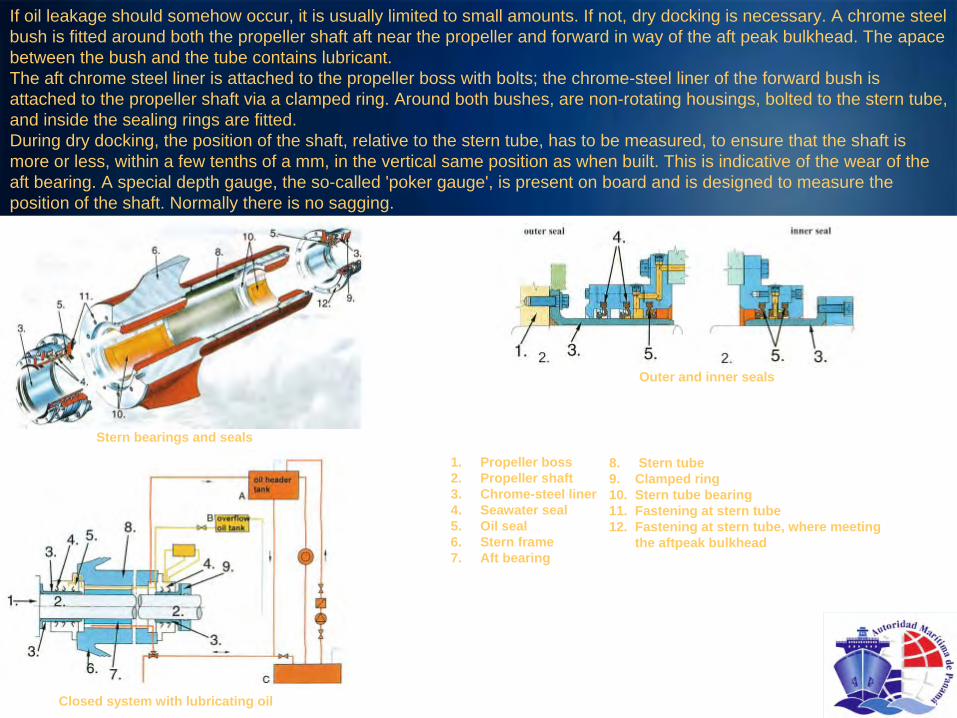
If oil leakage should somehow occur, it is usually limited to small amounts. If not, dry docking is necessary. A chrome steel bush is fitted around both the propeller shaft aft near the propeller and forward in way of the aft peak bulkhead. The apace between the bush and the tube contains lubricant.The aft chrome steel liner is attached to the propeller boss with bolts; the chrome-steel liner of the forward bush is attached to the propeller shaft via a clamped ring. Around both bushes, are non-rotating housings, bolted to the stern tube, and inside the sealing rings are fitted.During dry docking, the position of the shaft, relative to the stern tube, has to be measured, to ensure that the shaft is more or less, within a few tenths of a mm, in the vertical same position as when built. This is indicative of the wear of the aft bearing. A special depth gauge, the so-called 'poker gauge', is present on board and is designed to measure the position of the shaft. Normally there is no sagging.
Stern bearings and seals
Closed system with lubricating oil
Outer and inner seals
1.
Propeller boss2.
Propeller shaft3.
Chrome-steel liner4.
Seawater seal5.
Oil seal6.
Stern frame7.
Aft bearing
8.
Stern tube9.
Clamped ring10.
Stern tube bearing11.
Fastening at stern tube12.
Fastening at stern tube, where meeting the aftpeak
bulkhead

2.8 Water jet propulsionWater-jet propulsion is based on the reaction force of a high velocity
water jet at the stern of a (light displacement) ship, blown in aft direction.The main principles of the water jet are:-the impeller (propeller) draws in seawater through an inlet, usually in the (flat) bottom-the same impeller boosts the water pressure for the water flow-the water is pushed through a nozzle-the nozzle converts the water pressure into a high speed jet-the acceleration of the water flow generates a thrust force that
gives the ship its speed-for sailing astern, the water flow exiting from the nozzle can be reversed in the forward direction with reversing plate(s).The water jet has an electronic steering system. This means that
the orders from the bridge are immediately processed by micro processors.This makes it possible for the water jet, engine and gearbox to be controlled directly from the bridge.Along with yachts, many passenger and car ferries, rescue and patrol boats are nowadays equipped with water jets. In 1998 the first cargo ships were built with water jet propulsion.
The maximum speed of modern water jets lies around 70-75 knots (approximately 135 km/h). The fastest ferries can reach a
speed of approximately 50 knots. The advantages of water jets are:-No rotating parts under water. This makes it safe to maneuver in
shallow waters.-less resistance, especially at higher speeds, because there are no fittings (e.g. the rudder)-not protruding below the ship.-Excellent maneuvering capabilities. For instance, a jet powered ship can navigate sideways.-less sensitive to cavitation
titan propellers on fast ships.-High propulsion efficiencies of up to 72%.
Water jet with reversing bucket downShip driven by water jet propulsion

Cross-section of water jet (Wartsila
propulsion jets)
1.
Inlet2.
Driving shaft3.
Impeller4.
Hydraulic steering cylinder5.
Jetavator, steering part6.
Hydraulic cylinder that alters the direction of the propulsion
7.
Reversing plate, can be moved by the cylinder8.
Reverse section9.
Sealing box to prevent water from entering the ship
10.
Combined guide and thrust bearing11.
Nozzle
3. StabilizersRolling of a (fast) ship during sailing can be reduced by using stabilizing fins, by as much as 80 -
90%. The velocity of the water stream along the ship’s side can be used to reduce the rolling, by installing such fins, with a configuration of a flap-rudder, in a sideway direction protruding from the bilge strake,
and which can rotate around a shaft. The maximal rotation angle is up and down approximately 25°. When having an angle with the water’s direction, they produce lifting forces, similar to a rudder, upwards or downwards. When a ship is rolling, water flows along the sides in an undulating way.
The fin is operated such, that at any moment, a reaction force is produced, upward or downward, contrary to the acceleration of the ship side. The angle of attack of the fin profile is adjusted to the flow direction, upward or downward, depending on rolling speed, time, and ship speed. The fin is oscillated
by a hydraulic piston or
vane type motor. The angle of attack, the rotation speed and period are dictated by a
computer, receiving signals from sensors in the rotating shaft, comparing the produced force with the required force, and
from a gyro. The working force is maximized, but cavitation
is prevented. They are in use on passenger ships and yachts, for the comfort of the people on board, and on Ro-Ro ships and containerships to reduce the acceleration forces on
the cargo. Some heavy cargo ships use stabilizers for the same reason. A decrease in fuel consumption is claimed also. Normal installation comprises one fin on each side, but 4 fins are also installed. The fins can be retracted, in order not to stick out from the ship side when moored.

1.
Bridge control unit
2.
Main control unit
3.
Pump motor starter
4.
Local control unit
5.
Fin
6.
Stabilizer machinery unit
7.
Oil header tank
8.
Hydraulic power unit
Stabilizer
4. RuddersThe function of a rudder is to develop a transverse steering force on the aft side of a ship, using the reaction force of the water flowing along the ship (and the rudder). The rudder is usually located in the water flow aft of the propeller. Depending on the type of ship, the area of the rudder ranges from 1.5% to 10% of the underwater lateral area (length x draught).The rudder should be shaped in such a way that the water flow can be deviated as effectively as possible, in combination with minimal resistance. Giving the horizontal cross-section of the rudder a wing-profile satisfies these two demands. In fact, the rudder is a vertical wing, on which a lifting force is generated by the water-flow in the same way as an airplane wing, propeller blades and a
nozzle get a lift. This is also known as the rudder force. The drag should be as low as possible. The lifting force gives a turning moment around the ship's centre of displacement: this is
what rotates the ship.For slow speed maneuvering the rudder should cover the propeller
diameter as much as possible in order to make optimal use of the water flow of the propeller.The force that the steering engine must supply depends on the torque (force x distance) that must be applied to rotate the rudder.This force is the resultant (N) (see next slide). The total moment depends on:-the position of the rudder stock compared to the point of application of N.-The distance between the rudder stock and the leading edge of the rudder (balance).When the rudder is free hanging (spade type), the rudder stock must also be able to absorb the total bending forces of the rudder.

V = velocity of water flow
L = lift
D = drag
N = resultant force
-
= under pressure
+ = over pressure
A = distance between the rudder stock and the point of application of N
A controllable pitch propeller and a flap rudder
Depending on the rudder-profile, the rudder stock is located at 25 -
40% abaft leading edge of the rudder.Most rudders are hollow and empty. The inside is stiffened with horizontal and vertical profiles.The next sections will only describe free hanging rudders. In smaller vessels (like fishing boats), however, rudders are still
supported in specially constructed heels, or in case of mariner rudders at half height (bigger ships).The most common rudder types are:1.
spade rudder2.
flap rudder3.
mariner rudder4.
fish-tail rudder
4.1 Spade rudder
In terms of construction, the spade rudder is very simple because it has no supports. For this reason it is a very cheap rudder and it is widely applied, from yachts to fast ferries and
tankers. The rudder usually becomes narrower front top to bottom, to reduce the bending moment in the rudder shaft.
4.2 The Flap rudder
The flap rudder has a hinged flap at the back of the rudder blade. This flap is moved mechanically by the flap guide at the top of the rudder in such a way that the flap's taming angle is twice as large as the turning angle of the main rudder blade. The steering methods of the flap differ per type of flap rudder.
When the maximum rudder angle is 45°, the flap has amaximum angle of 90°
with respect to the ship. In this rudder position it is possible that 40% of the ship's propulsive force is directed sideways. In combination with a bow
thruster such a ship can navigate transversely.

1.
Transom
2.
Steering flat
3.
Aft perpendicular = rudder axle
4.
Rudder
5.
Rudder trunk
6.
Space for the rudder stock
7.
Ice –
protection
8.
Rudder dome (deadwood)
9.
Stern frame
10.
Wash bulkhead on centre line
11.
Stern frame centre
12.
Centre line propeller shaft
13.
Side girder
14.
Floor plate
Frame at aft perpendicular (frame 0)
Frame number 2Side view of the ship’s centre line
Side girder in stern
Top view

Spade rudder freely suspended from the rudder dome
Flap rudder
Flap rudder
1.
Rudder blade2.
Rudder-stock in rudder trunk
3.
Flap4.
Hinge line5.
Steering engine6.
Steering engine foundation
7.
Gland and bearing
8.
Rudder dome9.
Steadiment
bearing10.
Flap actuator
Current flows at maximum rudder angle
Advantages of flap rudders are:— extra maneuverability (that is, if the main rudder blade is as large as the spade rudder)— Course corrections
can be performed with smaller rudder angles. This means that the ship— loses less speed and therefore consumes less fuel.
Disadvantages are:— the price— vulnerability— the larger rudder forces require the rudder stock to be bigger.

4.3 The Mariner rudder
The Mariner rudder is used on large ships like container ships, bulk carriers, tankers and passenger liners. The rudder horn is integrated in the ship's construction
and the mariner rudder is attached to the stern post with the ability to rotate. This results in a robust rudder. Disadvantages of this construction are that there is a larger risk of cavitation
at the suspension points and that the cast construction is more expensive.
Mariner rudder
4.4 Fishtail rudderThe fishtail rudder has been developed for ships with a slow speed, less than 14 knots. The after edge of the rudder blade is provided with a friction increase, to give extra drag to the water around the rudder. This improves the maneuvering abilities.
Top view of a fishtail rudder5. Steering Gear
5.1 GeneralWhen on the bridge it is decided to alter the course, the automatic pilot or the helm is used to activate the steering engine, which, in turn, rotates the rudder stock and the rudder. The rudder carrier supports the rudder stock and the rudder. The rudder carrier also functions as a bearing around the rudder stock, and it seals the rudder trunk to prevent seawater from entering the ship by a gland.SOLAS demands that every steering engine should be equipped with
2 sets of pumps with separated power supply, and, consequently, also 2 servo sets, serving the hydraulic pumps. Both the ram and the rotary vane steering engines operate by hydraulic power.Both types of steering gear are equally common in shipping. The magnitude of the steering or rudder moment is expressed in kNm
(kilo-Newton-meter). In general the greatest rudder moment occurs at 30º-35º.5.2 Ram steering gearIn ram steering gear, the rudder stock is rotated by a tiller that, in its turn, is controlled by rams. A ram consists of a cylinder and a piston, the piston being moved by hydraulic pressure. The tiller and the rudder stock are often linked by a conical connection.Ram steering gear can have I ram, 2 rams
or 4 rams. If, in the case of one or two rams the cylinders are double acting, the steering engine can still operate through one
of the cylinders when the other one fails. A
4-ram system can be split in two and two for the same reason. This
is a requirement of SOLAS.

1.
Rudder stock
2.
Tiller
3.
Ram (piston + cylinder)
4.
Hydraulic lines
5.
Electro-motor
6.
Protection of coupling between electric motor and hydraulic power pack
7.
Pump in tank filled with oil (power pack)
Double acting cylinders in a ram steering gear Ram steering gear
5.3 Rotary vane steering gear
A rotary vane steering engine consists of a fixed casing, with inside the casing a rotor to which wings are attached. The casing provided with two similar fixed wings as are on the rotor. This arrangement divides the house into four chambers, two high pressure and two low pressure ones. A valve block directs hydraulic oil at high pressure into the chambers simultaneously, pushing/rotating the rotor and subsequently the rudder. If the rudder is rotated to the other side, the high-
pressure chambers become low pressure chambers and vice versa, The rudder stock is located in the center of the rotor; the rotor is pressed onto the conical section of the rudder stock. The wings and the fixed division blocks are provided with spring loaded plates which are the seals between the high and low pressure oil chambers.
Advantages of a rotary-vane steering gear engine over a ram-steering engine are:-it takes up less space-it is easier to build in-it has as integrated bearing-it has a constant rudder moment.
Disadvantage:-it is quite complicated to repair it.

1.
Rudder2.
Rotary vane steering gear with valve block3.
Electric motor with main hydraulic pump4.
Power units (to supply the hydraulic power to operate the valves in the valve block)
5.
Hydraulic oil tank6.
Emergency maneuvering console7.
Starter boxes electric motors8.
Bulkhead between engine room and steering gear room
9.
Bottom10.Entrance from engine room11.Hydraulic oil lines for
maneuvering and cross connections
Rotary vane:
1. Rudder stock2. Rotor with wings3. Fixed division blocks with oil lines4. Chambers (filled with oil)5. Electric motor6. Hydraulic pump

THANK YOU!