motor unit mu10, mu20, mu30 - abb ltd · motor unit mu10, mu20, mu30 s4cplus, m2001 ... 4.2.4 cable...
TRANSCRIPT

Product ManualMotor unitMU10, MU20, MU30S4Cplus, M2001
3HEA 506 200-102 Rev.A 2005-09
The information in this document is subject to alteration without prior notice and should not be regarded as an undertaking from ABB Automation Technologies AB. ABB Automation Technologies AB assumes no responsibility for errors that may occur in this document.
ABB Automation Technologies AB bears no responsibility for damage that is a consequence of using this document or the software or hardware described in this document.
The document, or parts of it, may not be reproduced or copied without prior permission from ABB Auto-mation Technologies AB. It may neither be imparted to a third party nor otherwise be used without autho-rization. Infringement hereof will be subject to action in accordance with applicable laws.
Further copies of this document can be obtained from ABB Automation Technologies AB at current prices.
2005 ABB Automation Technologies AB
ABB Automation Technologies ABRobotics & Manufacturing
SE-69582 LaxåSweden
1 Introduction 1 - 1
1.1 General 1-11.1.1 Areas of application 1-11.1.2 Motor sizes 1-1
1.2 Description 1-21.2.1 General 1-21.2.2 Serial Measurement Box 1-2
1.3 Brakes 1-31.3.1 General 1-31.3.2 Releasing the brakes 1-3
2 Technical specification 2 - 5
A Motors 2 - 5
2.1 Motor MU10 2-52.1.1 Illustration 2-52.1.2 Technical data 2-52.1.3 Brake 2-62.1.4 Dimensional diagrams 2-62.1.5 Wiring diagram 2-72.1.6 Torque curve 2-7
2.2 Motor MU20 2-82.2.1 Illustration 2-82.2.2 Technical data 2-82.2.3 Brake 2-92.2.4 Dimensional diagrams 2-92.2.5 Wiring diagram 2-102.2.6 Torque curve 2-10
2.3 Motor MU30 2-122.3.1 Illustration 2-122.3.2 Technical data 2-122.3.3 Brake 2-132.3.4 Dimensional diagrams 2-132.3.5 Wiring diagram 2-142.3.6 Torque curve 2-142.3.7 Torque curve Motor MU30+MU20 2-152.3.8 Torque curve Motor MU30+MU30 2-16
B Serial measurement boxes 3 - 17
2.4 Low voltage 3-172.4.1 One motor 3-172.4.2 Two motors 3-182.4.3 Four motors 3-192.4.4 Six motors 3-20
2.5 High voltage 3-212.5.1 One motor 3-21
3HEA 506 200-102 Rev.A 2005-09 i
2.5.2 Two motors 3-22
C Brake release box (BRB) 3 - 23
2.6 High voltage motor 3-23
3 Electrical installation 4 - 25
3.1 Installation of software 4-25
D One external axis 4 - 25
3.2 General 4-25
3.3 Installation into one cabinet for 1400, 2400, 4400, 6400R 4-25
3.4 Installation into one cabinet for IRB 6600, 7600 with serial measure-
ment box 4-27
3.5 Installation into one cabinet for 6600, 7600 with brake release box4-29
E Several external axes 4 - 31
3.6 Introduction 4-313.6.1 General 4-313.6.2 Operation 4-313.6.3 Limitation 1: 4-313.6.4 Limitation 2: 4-32
3.7 Installation into one cabinet for 1400, 2400, 4400, 6400R 4-33
3.8 Installation into one cabinet for IRB 6600, 7600 4-35
4 Order information 5 - 37
4.1 Introduction 5-374.1.1 General 5-374.1.2 Ordering cables 5-37
F Motor unit IRB 1400, 2400, 4400, 6400R 5 - 37
4.2 One motor 5-374.2.1 Motors 5-374.2.2 Serial Measurement Box (SMB) 5-384.2.3 Cables between the SMB and motor 5-384.2.4 Cable for external axis from the robot cabinet to SMB 5-384.2.5 Cable for external axis from the signal cable in the robot cabinet to SMB
5-384.2.6 Cable for external axis from SMB to robot 5-39
4.3 Two to six motors 5-404.3.1 Motors 5-404.3.2 Serial measurement boxes (SMB) 5-404.3.3 Cables (SMB-motor) 5-404.3.4 Cables for external axes and several motors (cabinet-SMB) 5-414.3.5 Robot cabinet cable for MS2 5-41
G Motor unit IRB 6600, 7600 5 - 41
ii 3HEA 506 200-102 Rev.A 2005-09

4.4 One or two motors 5-414.4.1 Motors 5-414.4.2 Serial Measurement Box (SMB) 5-424.4.3 Brake release box (BRB) for one motor 5-424.4.4 Cable between SMB and motor 5-424.4.5 Cable between DDU cabinet and BRB/SMB for one motor 5-424.4.6 Cable between DDU cabinet and SMB for two motors 5-434.4.7 Cable between robot cabinet and SMB for one or two motors 5-434.4.8 Cable between robot and BRB 5-43
4.5 Notes: 5-44
3HEA 506 200-102 Rev.A 2005-09 iii

iv 3HEA 506 200-102 Rev.A 2005-09
IntroductionGeneral
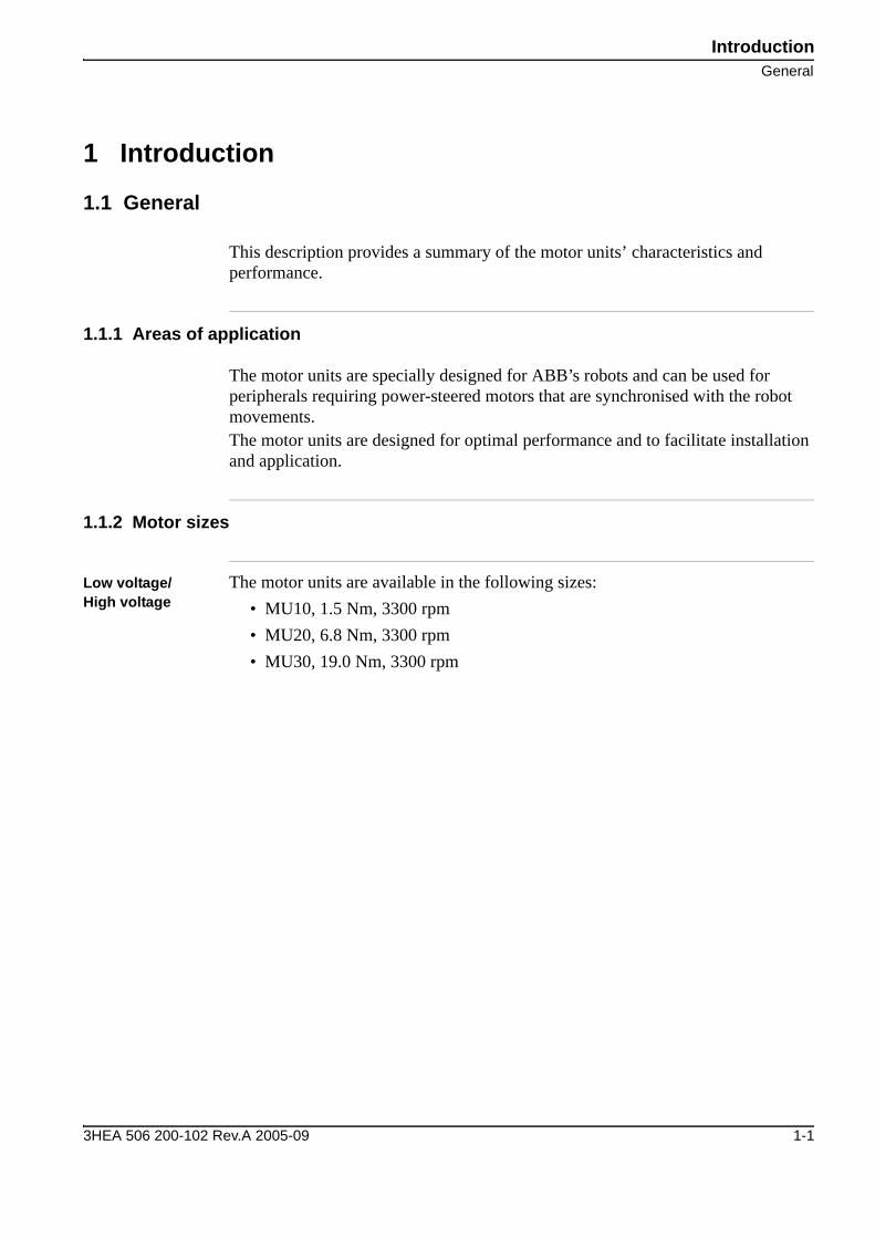
1 Introduction
1.1 General
This description provides a summary of the motor units’ characteristics and performance.
1.1.1 Areas of application
The motor units are specially designed for ABB’s robots and can be used for peripherals requiring power-steered motors that are synchronised with the robot movements. The motor units are designed for optimal performance and to facilitate installation and application.
1.1.2 Motor sizes
Low voltage/ High voltage
The motor units are available in the following sizes:• MU10, 1.5 Nm, 3300 rpm• MU20, 6.8 Nm, 3300 rpm• MU30, 19.0 Nm, 3300 rpm
3HEA 506 200-102 Rev.A 2005-09 1-1

IntroductionDescription
1.2 Description
1.2.1 General
The motor units are power-operated and function as external axes. The motors are controlled by drive units mounted either in the robot’s switch box or in a separate housing.
• A motor can be linked to the robot system as an integrated external axis. • An integrated external axis can move synchronously with the robot axes.• A complete motor unit comprises a serial measurement box, motors, parameter
diskette and a number of standardised cables.
1.2.2 Serial Measurement Box
The serial measurement box contains a serial measurement card (with battery backup) and push-buttons for releasing the brakes. The serial measurement box can, if required, be located up to a recommended maximum of 15 m from the motor.
If material handlers (MH), one external axis and option 2204 or 2200 are selected, the serial measurement box can be replaced by a brake release box.
1-2 3HEA 506 200-102 Rev.A 2005-09

IntroductionBrakes
1.3 Brakes
1.3.1 General
All motors described in this manual are equipped with electric brakes that are “on” when they are not energised. This brake is not an operating brake.This means that with normal operations the p-box or operator's panel are to be used to stop. They can be released in several different ways, and are described in the following section.
1.3.2 Releasing the brakes
The various methods for releasing the brakes manually are specified in the table below.
When Notes
When the brake release/serial measurement box is connected to the Robot Control Cabinet.
The brake will be released when the button in the box is pressed.
24VDC/1A supply unit is connected between MP.JB1 output c5 (0V) and c4(+24VDC) in the brake release/serial measurement box.
The brake will be released when the button in the box is presseda.
a. For two external axes, the brake is released for axis 8 when button 8 is pressed,see Brake release box (BRB) section C
24V is connected, for two external axes, between MP.JB1 output a5 (0V) and a4 (+24V DC)
The brake for axis 7 will be released when button 7 in the box is pressed.
3HEA 506 200-102 Rev.A 2005-09 1-3

IntroductionBrakes
1-4 3HEA 506 200-102 Rev.A 2005-09
Technical specificationMotors
2 Technical specification
A Motors
2.1 Motor MU10
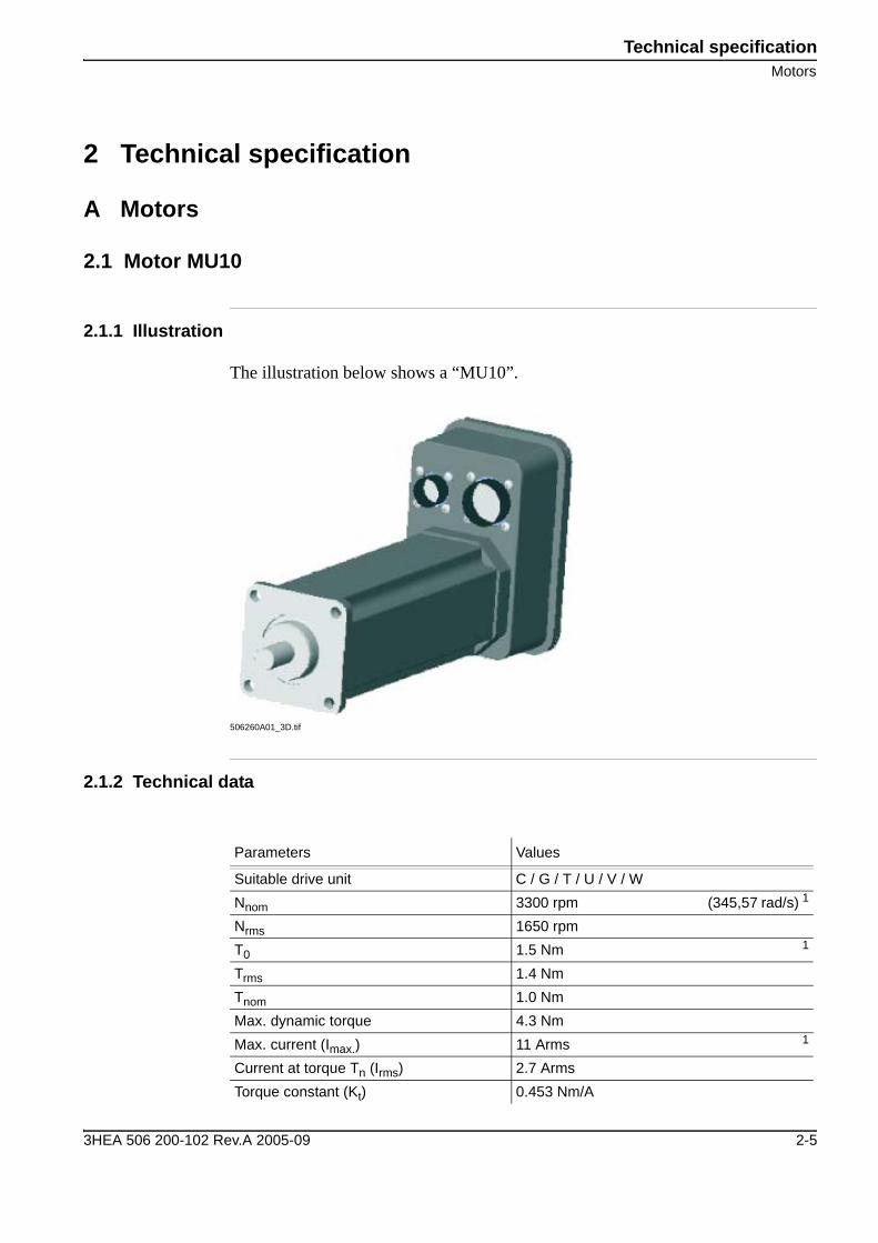
2.1.1 Illustration
The illustration below shows a “MU10”.
506260A01_3D.tif
2.1.2 Technical data
Parameters Values
Suitable drive unit C / G / T / U / V / WNnom 3300 rpm (345,57 rad/s) 1
Nrms 1650 rpmT0 1.5 Nm 1
Trms 1.4 NmTnom 1.0 NmMax. dynamic torque 4.3 Nm Max. current (Imax.) 11 Arms 1
Current at torque Tn (Irms) 2.7 ArmsTorque constant (Kt) 0.453 Nm/A
3HEA 506 200-102 Rev.A 2005-09 2-5

Technical specificationMotors
2.1.3 Brake
2.1.4 Dimensional diagrams
506276a01
Voltage constant, (Ke(Urms) 0.262 1
Winding resistance/phase (R) 1.09 ohm 1
Winding inductance/phase (L) 3.42 mH 1
Mass torque incl. brake (J) 0.00008 kgm2 1
Number of pairs of poles 3 1
Weight (M) 4.4 kgTemperature range +5° - +45°CNominal output 0.25 kWPeak output 1.4 kWDegree of protection IP 67
1.Used in the configurationfile
Parameters Values
Min. torque 0.9 NmMax. torque 1.4 NmVoltage 24 ± 10% V DCPower consumption at 20° C 12 W
7458
74 5890
R15(4x)
Ø7,5(4x)45140
260203
155
9 7,7
34
Ø36
,8 h
916
Ø14
j65h
7
2-6 3HEA 506 200-102 Rev.A 2005-09

Technical specificationMotors
2.1.5 Wiring diagram
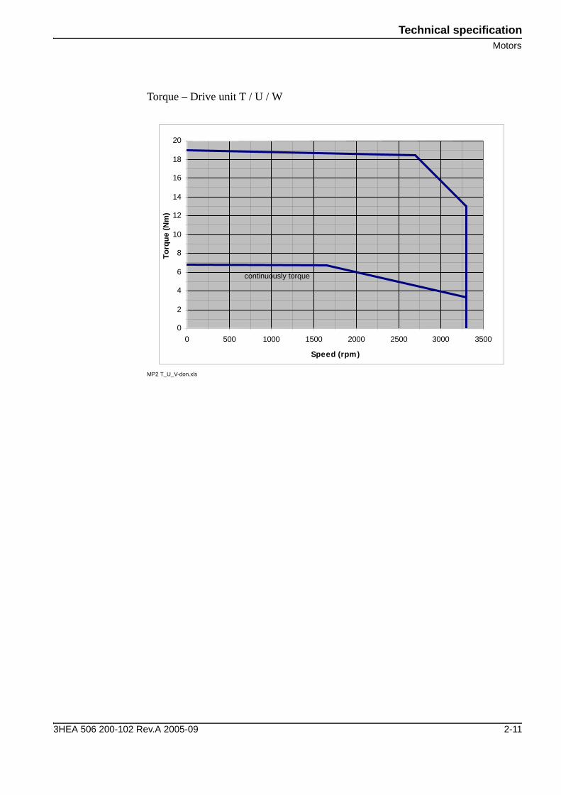
2.1.6 Torque curve
Torque - Drive unit C / G / T / U / V / W
MP1 C-don.xls
ResolverForce
Yellow8P BURNDY23P BURNDY
Green
Red
PTC
YellowYellow Brake
Gn/Ye
A
G
JK
L
A
M
M
C
EW
X
C
B
V U
3
OVX
YOVY
BkOVEXCEXC
Earth
S1S3
S4S2
Rd
Rd/Wh
Bk/Wh/Bu Ye Ye/Wh
R2R1
B
D
EF
0
1
2
3
4
5
0 500 1000 1500 2000 2500 3000 3500
Speed (rpm)
Torq
ue (N
m)
continuously torque
3HEA 506 200-102 Rev.A 2005-09 2-7
Technical specificationMotors
2.2 Motor MU20
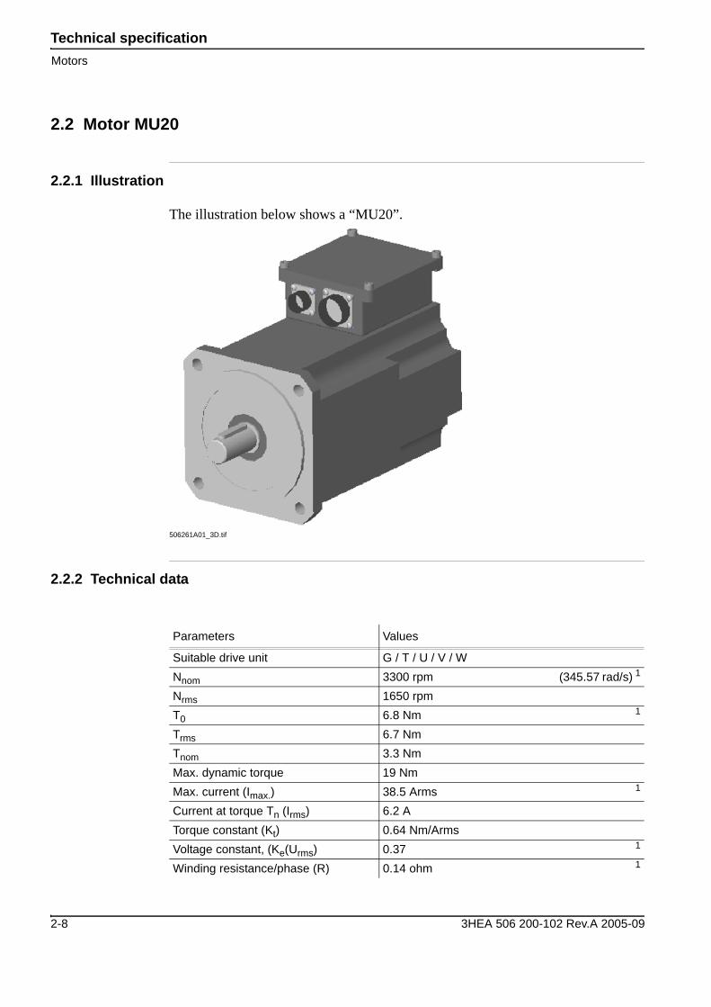
2.2.1 Illustration
The illustration below shows a “MU20”.
506261A01_3D.tif
2.2.2 Technical data
Parameters Values
Suitable drive unit G / T / U / V / WNnom 3300 rpm (345.57 rad/s) 1
Nrms 1650 rpmT0 6.8 Nm 1
Trms 6.7 NmTnom 3.3 NmMax. dynamic torque 19 NmMax. current (Imax.) 38.5 Arms 1
Current at torque Tn (Irms) 6.2 ATorque constant (Kt) 0.64 Nm/ArmsVoltage constant, (Ke(Urms) 0.37 1
Winding resistance/phase (R) 0.14 ohm 1
2-8 3HEA 506 200-102 Rev.A 2005-09

Technical specificationMotors
2.2.3 Brake
2.2.4 Dimensional diagrams
Dim_Ritn_MU20.wmf
Winding inductance/phase (L) 2.76 mH 1
Mass torque incl. brake (J) 0.00092 kgm2 1
Number of pairs of poles 3 1
Weight (M) 13.5 kgTemperature range +5° - +45°CNominal output 1.2 kWPeak output 4.2 kWDegree of protection IP 67
1.Used in the configurationfile
Parameters Values
Min. torque 16 NmMax. torque 25.6 NmVoltage 24 ± 10% V DCPower consumption at 20° C 20 W
3HEA 506 200-102 Rev.A 2005-09 2-9

Technical specificationMotors
2.2.5 Wiring diagram
2.2.6 Torque curve
Torque – Drive unit G / V
MP2 G_V-don.xls
ResolverForce
Yellow8P BURNDY23P BURNDY
Green
Red
PTC
YellowYellow Brake
Gn/Ye
A
G
JK
L
A
M
M
C
EW
X
C
B
V U
3
OVX
YOVY
BkOVEXCEXC
Earth
S1S3
S4S2
Rd
Rd/Wh
Bk/Wh/Bu Ye Ye/Wh
R2R1
B
D
EF
B
D
F
H
0
2
4
6
8
10
12
14
16
18
20
0 500 1000 1500 2000 2500 3000 3500
Speed (rpm)
Torq
ue (N
m)
continiuously torque
2-10 3HEA 506 200-102 Rev.A 2005-09
Technical specificationMotors
Torque – Drive unit T / U / W
MP2 T_U_V-don.xls
0
2
4
6
8
10
12
14
16
18
20
0 500 1000 1500 2000 2500 3000 3500
Speed (rpm)
Torq
ue (N
m)
continuously torque
3HEA 506 200-102 Rev.A 2005-09 2-11
Technical specificationMotors
2.3 Motor MU30
2.3.1 Illustration
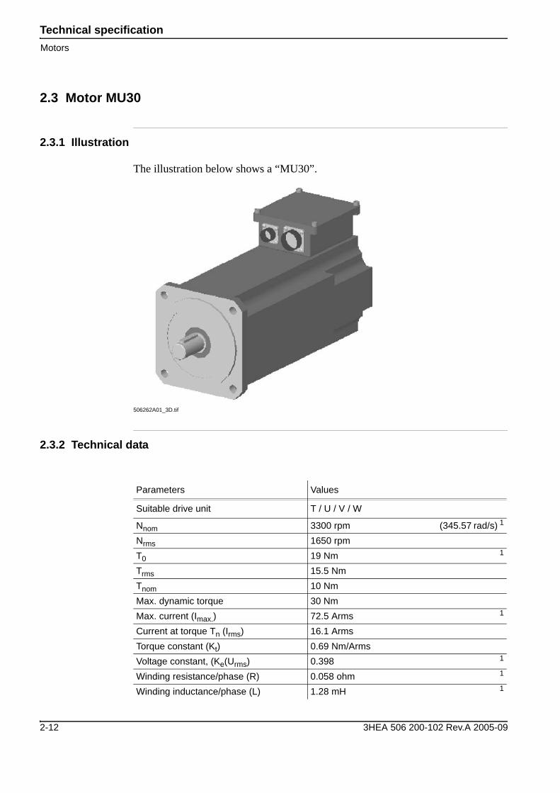
The illustration below shows a “MU30”.
506262A01_3D.tif
2.3.2 Technical data
Parameters Values
Suitable drive unit T / U / V / W
Nnom 3300 rpm (345.57 rad/s) 1
Nrms 1650 rpmT0 19 Nm 1
Trms 15.5 NmTnom 10 NmMax. dynamic torque 30 NmMax. current (Imax.) 72.5 Arms 1
Current at torque Tn (Irms) 16.1 ArmsTorque constant (Kt) 0.69 Nm/ArmsVoltage constant, (Ke(Urms) 0.398 1
Winding resistance/phase (R) 0.058 ohm 1
Winding inductance/phase (L) 1.28 mH 1
2-12 3HEA 506 200-102 Rev.A 2005-09

Technical specificationMotors
2.3.3 Brake
2.3.4 Dimensional diagrams
Dim_Ritn_MU30.wmf
Mass torque incl. brake (J) 0.00213 kgm2 1
Number of pairs of poles 3 1
Weight (M) 23.5 kgTemperature range +5° - +45°CNominal output 2.7 kWPeak output 12.1 kWDegree of protection IP 67
1.Used in the configurationfile
Parameters Values
Min. torque 21 NmMax. torque 33.6 NmVoltage 24 ± 10% V DCPower consumption at 20° C 28 W
3HEA 506 200-102 Rev.A 2005-09 2-13

Technical specificationMotors
2.3.5 Wiring diagram
2.3.6 Torque curve
Torque – Drive unit T
MP3 T-don.xls
ResolverForce
Yellow8P BURNDY23P BURNDY
Green
Red
PTC
YellowYellow Brake
Gn/Ye
A
G
JK
L
A
M
M
C
EW
X
C
B
V U
3
OVX
YOVY
BkOVEXCEXC
Earth
S1S3
S4S2
Rd
Rd/Wh
Bk/Wh/Bu Ye Ye/Wh
R2R1
B
D
EF
B
D
F
H
N
V
U
S
02468
101214161820222426283032
0 500 1000 1500 2000 2500 3000 3500
Speed (rpm)
Torq
ue (N
m)
continuously torque
2-14 3HEA 506 200-102 Rev.A 2005-09

Technical specificationMotors
Torque – Drive unit U / W
MP3 U_W-don.xls
2.3.7 Torque curve Motor MU30+MU20
Torque – Drive unit GT (continuously available torque 0 rpm)
Torque – Drive unit GT
02468
101214161820222426283032
0 500 1000 1500 2000 2500 3000 3500
Speed (rpm)
Torq
ue (N
m)
continuously torque
Large -T
Medium -G
Nm
Nm
3HEA 506 200-102 Rev.A 2005-09 2-15

Technical specificationMotors
2.3.8 Torque curve Motor MU30+MU30
Torque – Drive unit GT (continuously available torque 0 rpm)
Torque – Drive unit GT
Large1 -T
Large2 -GNm
Nm
2-16 3HEA 506 200-102 Rev.A 2005-09

Technical SpecificationSerial measurement boxes
B Serial measurement boxes
2.4 Low voltage
2.4.1 One motor
3HXD 0100-89
Part Quantity Name Part number Remarks
1 1 Serial measurement card 3HEA 505 966-8802 1 Connecting limit switches 3HXD 0100-122
1
∅ 6.5 (4x)10
350
330300
180
200
166
150
29.5
2
3HEA 506 200-102 Rev.A 2005-09 3-17
Technical SpecificationSerial measurement boxes
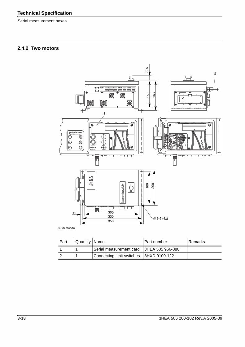
2.4.2 Two motors
3HXD 0100-90
Part Quantity Name Part number Remarks
1 1 Serial measurement card 3HEA 505 966-8802 1 Connecting limit switches 3HXD 0100-122
∅ 6.5 (4x)
10
350330300
180
200
166
150
29.5
2
1
3-18 3HEA 506 200-102 Rev.A 2005-09
Technical SpecificationSerial measurement boxes
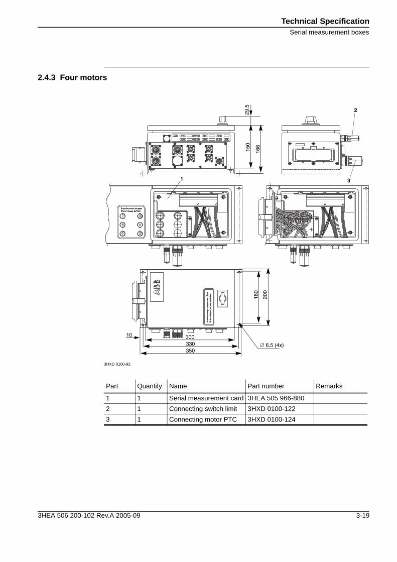
2.4.3 Four motors
3HXD 0100-92
Part Quantity Name Part number Remarks
1 1 Serial measurement card 3HEA 505 966-8802 1 Connecting switch limit 3HXD 0100-1223 1 Connecting motor PTC 3HXD 0100-124
∅ 6.5 (4x)
10
350330300
180
200
166
150
29.5
1
2
3
3HEA 506 200-102 Rev.A 2005-09 3-19
Technical SpecificationSerial measurement boxes
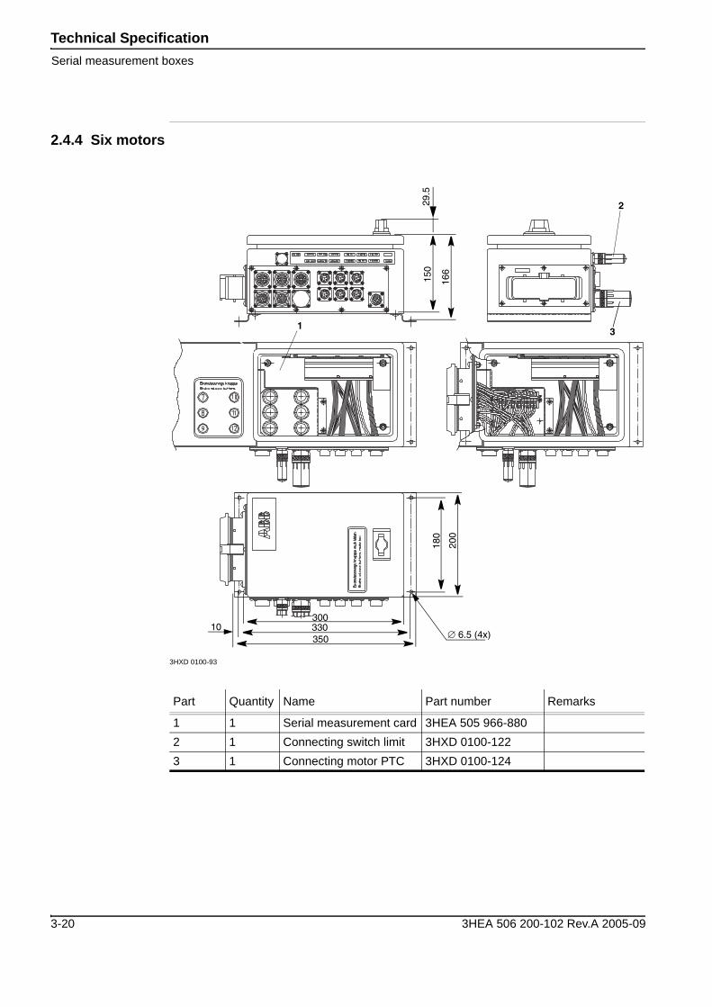
2.4.4 Six motors
3HXD 0100-93
Part Quantity Name Part number Remarks
1 1 Serial measurement card 3HEA 505 966-8802 1 Connecting switch limit 3HXD 0100-1223 1 Connecting motor PTC 3HXD 0100-124
∅ 6.5 (4x)10
350330300
180
200
166
150
29.5
1
2
3
3-20 3HEA 506 200-102 Rev.A 2005-09
Technical SpecificationSerial measurement boxes
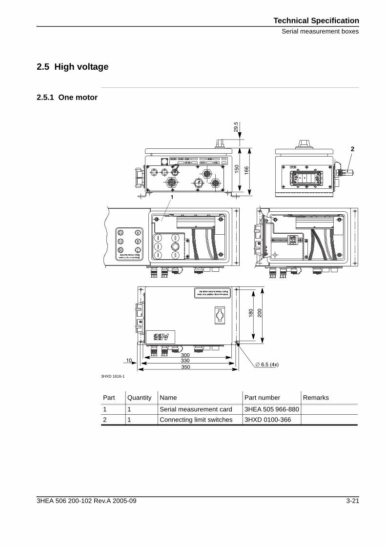
2.5 High voltage
2.5.1 One motor
3HXD 1616-1
Part Quantity Name Part number Remarks
1 1 Serial measurement card 3HEA 505 966-8802 1 Connecting limit switches 3HXD 0100-366
2
∅ 6.5 (4x)10
350330300
180
200
166
150
29.5
1
3HEA 506 200-102 Rev.A 2005-09 3-21
Technical SpecificationSerial measurement boxes
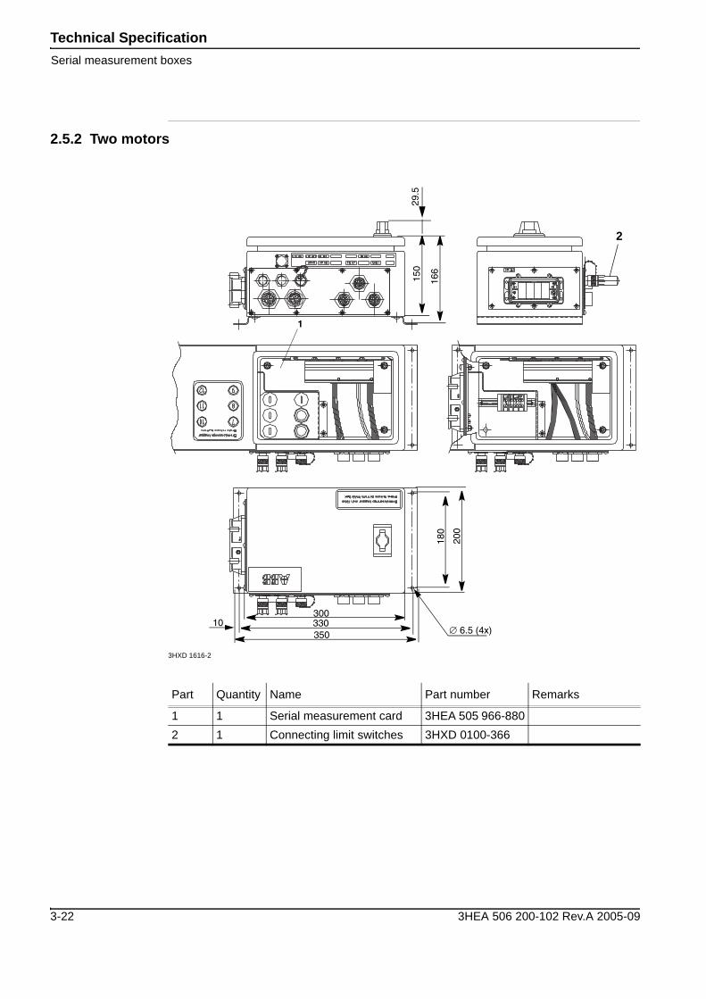
2.5.2 Two motors
3HXD 1616-2
Part Quantity Name Part number Remarks
1 1 Serial measurement card 3HEA 505 966-8802 1 Connecting limit switches 3HXD 0100-366
2
∅ 6.5 (4x)10
350330300
180
200
166
150
29.5
1
3-22 3HEA 506 200-102 Rev.A 2005-09
Technical SpecificationBrake release box (BRB)
C Brake release box (BRB)
2.6 High voltage motor
Part Quantity Name Part number Remarks
1 1 Brake release buttons2 2 Connecting limit switches 3HXD 0100-363
MP.JB1
LP.JB1LP.JB1
MP.M7
LS1.JB1
FB.M7LS2.JB1
BR.BF7
2
1
3HEA 506 200-102 Rev.A 2005-09 3-23
Technical SpecificationBrake release box (BRB)
3-24 3HEA 506 200-102 Rev.A 2005-09

Electrical installationOne external axis
3 Electrical installation
3.1 Installation of software
The system parameters for the motor package are on the diskette included in the delivery. There are files on this diskette that suit the most fequently occurring combinations of drive and measuring systems that can be loaded via RobInstall.The parameters can be loaded either via:
• The programming box:“System parameters / Load - replace parameters”
• or when booting using RobInstall:“Additional Data / Additional Parameters”.
The files on the diskette are in a tree structure and you select the file required depending on the location of the drive unit and then depending on the size of motor.The parameters are a basis for continued work. It is therefore always necessary to change either the name or the acceleration data, transmission (gear ratio), etc.See also the User’s Guide 3HAC 9299 “Hardware option / External Axes”.
D One external axis
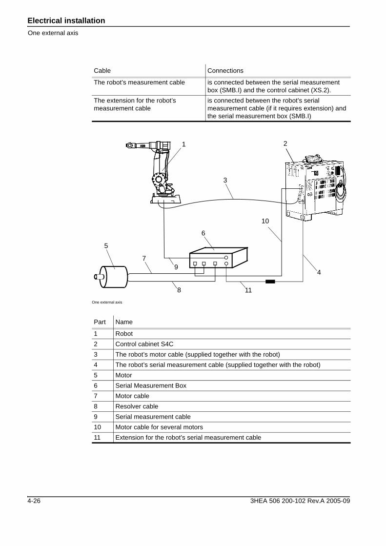
3.2 General
One external axis is normally connected to the robot’s serial measurement system, one (MS1) in series with the robot.
3.3 Installation into one cabinet for 1400, 2400, 4400, 6400R
Connect the motor unit as follows:
Cable Connections
The external axis’ serial measurement cable
is connected between the serial measurement box (SMB.I) and the robot foot (R1.SMB).
The resolver cable is connected between the serial measurement box (FB.M7) and the motor.
The motor cable is connected between the serial measurement box (MP.M7) and the motor.
The external axis’ motor cable is connected between the serial measurement box (MP.JB1) and the control cabinet (XS.7).
The robot’s motor cable is connected between the robot foot (R1.MP) and the control cabinet (XS.1).
3HEA 506 200-102 Rev.A 2005-09 4-25
Electrical installationOne external axis
One external axis
The robot’s measurement cable is connected between the serial measurement box (SMB.I) and the control cabinet (XS.2).
The extension for the robot’s measurement cable
is connected between the robot’s serial measurement cable (if it requires extension) and the serial measurement box (SMB.I)
Part Name
1 Robot2 Control cabinet S4C3 The robot’s motor cable (supplied together with the robot)4 The robot’s serial measurement cable (supplied together with the robot)5 Motor6 Serial Measurement Box7 Motor cable8 Resolver cable9 Serial measurement cable10 Motor cable for several motors11 Extension for the robot’s serial measurement cable
Cable Connections
21
5
7
8
4
3
10
9
6
11
4-26 3HEA 506 200-102 Rev.A 2005-09
Electrical installationOne external axis
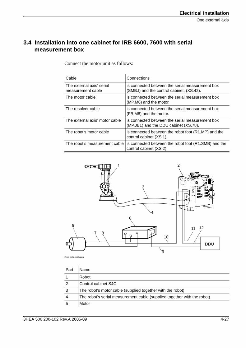
3.4 Installation into one cabinet for IRB 6600, 7600 with serial measurement box
Connect the motor unit as follows:
One external axis
Cable Connections
The external axis’ serial measurement cable
is connected between the serial measurement box (SMB.I) and the control cabinet, (XS.42).
The motor cable is connected between the serial measurement box (MP.M8) and the motor.
The resolver cable is connected between the serial measurement box (FB.M8) and the motor.
The external axis’ motor cable is connected between the serial measurement box (MP.JB1) and the DDU cabinet (XS.78).
The robot’s motor cable is connected between the robot foot (R1.MP) and the control cabinet (XS.1).
The robot’s measurement cable is connected between the robot foot (R1.SMB) and the control cabinet (XS.2).
Part Name
1 Robot2 Control cabinet S4C3 The robot’s motor cable (supplied together with the robot)4 The robot’s serial measurement cable (supplied together with the robot)5 Motor
21
5
7
9
4
3
11
10
6
DDU
128
3HEA 506 200-102 Rev.A 2005-09 4-27
Electrical installationOne external axis
6 Serial Measurement Box7 Motor cable8 Resolver cable9 Motor cable (external axis)10 Serial measurement cable (external axis)11 Signal cable (supplied with DDU cabinet)12 Power cable (supplied with DDU cabinet)
Part Name
4-28 3HEA 506 200-102 Rev.A 2005-09
Electrical installationOne external axis
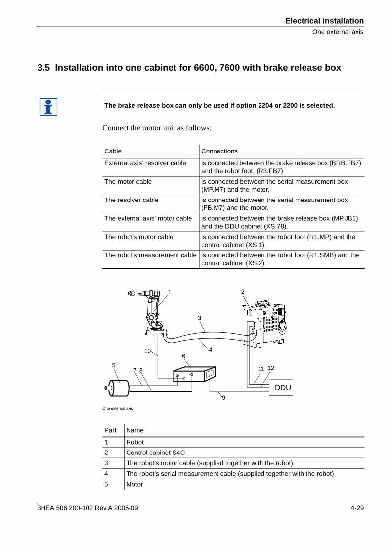
3.5 Installation into one cabinet for 6600, 7600 with brake release box
Connect the motor unit as follows:
One external axis
The brake release box can only be used if option 2204 or 2200 is selected.
Cable Connections
External axis’ resolver cable is connected between the brake release box (BRB.FB7) and the robot foot, (R3.FB7)
The motor cable is connected between the serial measurement box (MP.M7) and the motor.
The resolver cable is connected between the serial measurement box (FB.M7) and the motor.
The external axis’ motor cable is connected between the brake release box (MP.JB1) and the DDU cabinet (XS.78).
The robot’s motor cable is connected between the robot foot (R1.MP) and the control cabinet (XS.1).
The robot’s measurement cable is connected between the robot foot (R1.SMB) and the control cabinet (XS.2).
Part Name
1 Robot2 Control cabinet S4C3 The robot’s motor cable (supplied together with the robot)4 The robot’s serial measurement cable (supplied together with the robot)5 Motor
21
58
9
4
3
11
106
DDU
127
3HEA 506 200-102 Rev.A 2005-09 4-29
Electrical installationOne external axis
6 Brake release box7 Motor cable8 Resolver cable9 Motor cable (external axis)10 Serial measurement cable (external axis)11 Signal cable (supplied with DDU cabinet)12 Power cable (supplied with DDU cabinet)
Part Name
4-30 3HEA 506 200-102 Rev.A 2005-09
Electrical installationSeveral external axes
E Several external axes
3.6 Introduction
3.6.1 General
Several external axes are connected to the robot’s serial measurement system two (MS2).All S4C and S4C plus robot system can use up to six external axes, but one extra cabinet is required for the electronics in the following cases:
• For IRB 4400/6400 for two or more axes• For IRB 1400/2400 for four or more axes
3.6.2 Operation
For simultaneous operation of four or more Medium or Large motors from the same control system, certain parameters are limited:One S4C and S4C plus control system with external axis cabinet for external axes can as a maximum be equipped with 3 GT drive units, i.e. 3 T units and 3 G units, mounted in pairs in a GT module with common power pack. These are configured in the serial measurement box as follows:
• 7, 9 and 11, T unit• 8, 10 and 12, G unit
3.6.3 Limitation 1:
Operation of a Motor MU10 with a G drive unit or a Motor MU20 or Motor MU30 with a T drive unit. Performance is shown in the torque curves in chapter 2.3.7 and in chapter 2.3.8.
If four or more MU20 or MU30 motor units are operated from a control cabinet, performance may be reduced somewhat when the motors are run simultaneously, with high outgoing torque. The control cabinet cannot deliver maximum power to more than three MU20 or MU30 motors at the same time.
3HEA 506 200-102 Rev.A 2005-09 4-31
Electrical installationSeveral external axes
3.6.4 Limitation 2:
The GT drive units have their maximum current set to a lower value than a separate G or T unit. Therefore, simultaneous operation of axes 7-8, 9-10 and 11-12 should be avoided, if the reciprocal cycle makes high use of the motors. Applicable mean torque per motor pair is shown in the torque curves.
4-32 3HEA 506 200-102 Rev.A 2005-09
Electrical installationSeveral external axes
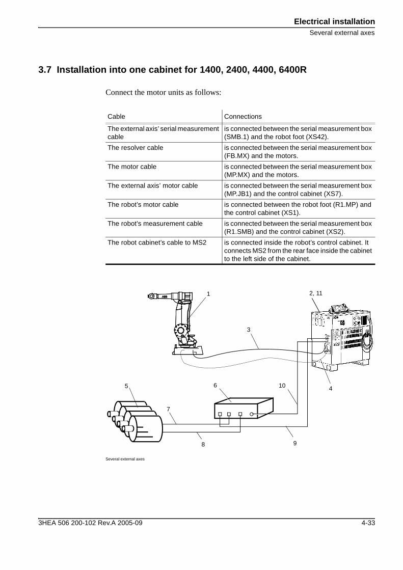
3.7 Installation into one cabinet for 1400, 2400, 4400, 6400R
Connect the motor units as follows:
Several external axes
Cable Connections
The external axis’ serial measurement cable
is connected between the serial measurement box (SMB.1) and the robot foot (XS42).
The resolver cable is connected between the serial measurement box (FB.MX) and the motors.
The motor cable is connected between the serial measurement box (MP.MX) and the motors.
The external axis’ motor cable is connected between the serial measurement box (MP.JB1) and the control cabinet (XS7).
The robot’s motor cable is connected between the robot foot (R1.MP) and the control cabinet (XS1).
The robot’s measurement cable is connected between the serial measurement box (R1.SMB) and the control cabinet (XS2).
The robot cabinet’s cable to MS2 is connected inside the robot’s control cabinet. It connects MS2 from the rear face inside the cabinet to the left side of the cabinet.
2, 111
5
7
8
4
3
106
9
3HEA 506 200-102 Rev.A 2005-09 4-33
Electrical installationSeveral external axes
Part Name
1 Robot2 Control cabinet S4C3 The robot’s motor cable (supplied together with the robot)4 The robot’s serial measurement cable (supplied together with the robot)5 Motors6 Serial Measurement Box7 Motor cables8 Resolver cables9 Motor cable for several motors10 Serial measurement cable, external axis11 The robot’s cable to the cabinet for MS2
4-34 3HEA 506 200-102 Rev.A 2005-09

Electrical installationSeveral external axes
3.8 Installation into one cabinet for IRB 6600, 7600
Connect the motor units as follows:
Several external axes
Cable Connections
The external axis’ serial measurement cable
is connected between the serial measurement box (SMB.1) and the control cabinet (XS42).
The resolver cable is connected between the serial measurement box (FB.MX) and the motors.
The motor cable is connected between the serial measurement box (MP.MX) and the motors.
The external axis’ motor cable
is connected between the serial measurement box (MP.JB1) and DDU cabinet (XS78).
The robot’s motor cable is connected between the robot foot (R1.MP) and the control cabinet (XS1).
The robot’s measurement cable
is connected between the serial measurement box (R1.SMB) and the control cabinet (XS2).
Part Name
1 Robot2 Control cabinet S4C3 The robot’s motor cable (supplied together with the robot)4 The robot’s serial measurement cable (supplied together with the robot)5 Motors6 Serial Measurement Box
21
5
7
9
4
3
106
DDU8
11 12
3HEA 506 200-102 Rev.A 2005-09 4-35

Electrical installationSeveral external axes
7 Motor cables8 Resolver cables9 Motor cabling, (external axes)10 Serial measurement cable, (external axes)11 Signal cable (supplied with DDU cabinet)12 Power cable (supplied with DDU cabinet)
Part Name
4-36 3HEA 506 200-102 Rev.A 2005-09
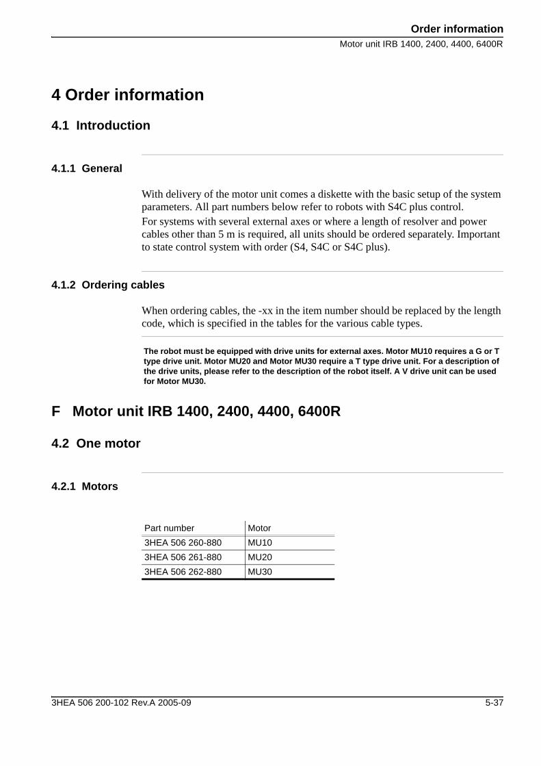
Order informationMotor unit IRB 1400, 2400, 4400, 6400R
4 Order information
4.1 Introduction
4.1.1 General
With delivery of the motor unit comes a diskette with the basic setup of the system parameters. All part numbers below refer to robots with S4C plus control.For systems with several external axes or where a length of resolver and power cables other than 5 m is required, all units should be ordered separately. Important to state control system with order (S4, S4C or S4C plus).
4.1.2 Ordering cables
When ordering cables, the -xx in the item number should be replaced by the length code, which is specified in the tables for the various cable types.
F Motor unit IRB 1400, 2400, 4400, 6400R
4.2 One motor
4.2.1 Motors
The robot must be equipped with drive units for external axes. Motor MU10 requires a G or T type drive unit. Motor MU20 and Motor MU30 require a T type drive unit. For a description of the drive units, please refer to the description of the robot itself. A V drive unit can be used for Motor MU30.
Part number Motor3HEA 506 260-880 MU103HEA 506 261-880 MU203HEA 506 262-880 MU30
3HEA 506 200-102 Rev.A 2005-09 5-37

Order informationMotor unit IRB 1400, 2400, 4400, 6400R
4.2.2 Serial Measurement Box (SMB)
4.2.3 Cables between the SMB and motor
4.2.4 Cable for external axis from the robot cabinet to SMB
4.2.5 Cable for external axis from the signal cable in the robot cabinet to SMB
Part number Serial Measurement Box3HXD 0100-89 SMB for one motor
Part number Cable Length3HXD 1250-xx Resolver cable3HXD 1249-xx Motor cable
-15 1.5 m-30 3 m-50 5 m-70 7 m-150 15 m
Part number Cable Length3HXD 1253-xx Serial measurement cable for external
axis-30 3 m-50 5 m-70 7 m-150 15 m
Part number Cable Length3HXD 1443-30 Signal cable for external axis 3 m
5-38 3HEA 506 200-102 Rev.A 2005-09
Order informationMotor unit IRB 1400, 2400, 4400, 6400R
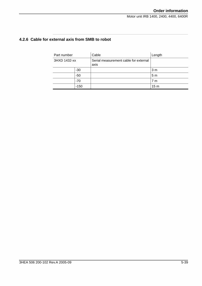
4.2.6 Cable for external axis from SMB to robot
Part number Cable Length3HXD 1432-xx Serial measurement cable for external
axis-30 3 m-50 5 m-70 7 m-150 15 m
3HEA 506 200-102 Rev.A 2005-09 5-39
Order informationMotor unit IRB 1400, 2400, 4400, 6400R
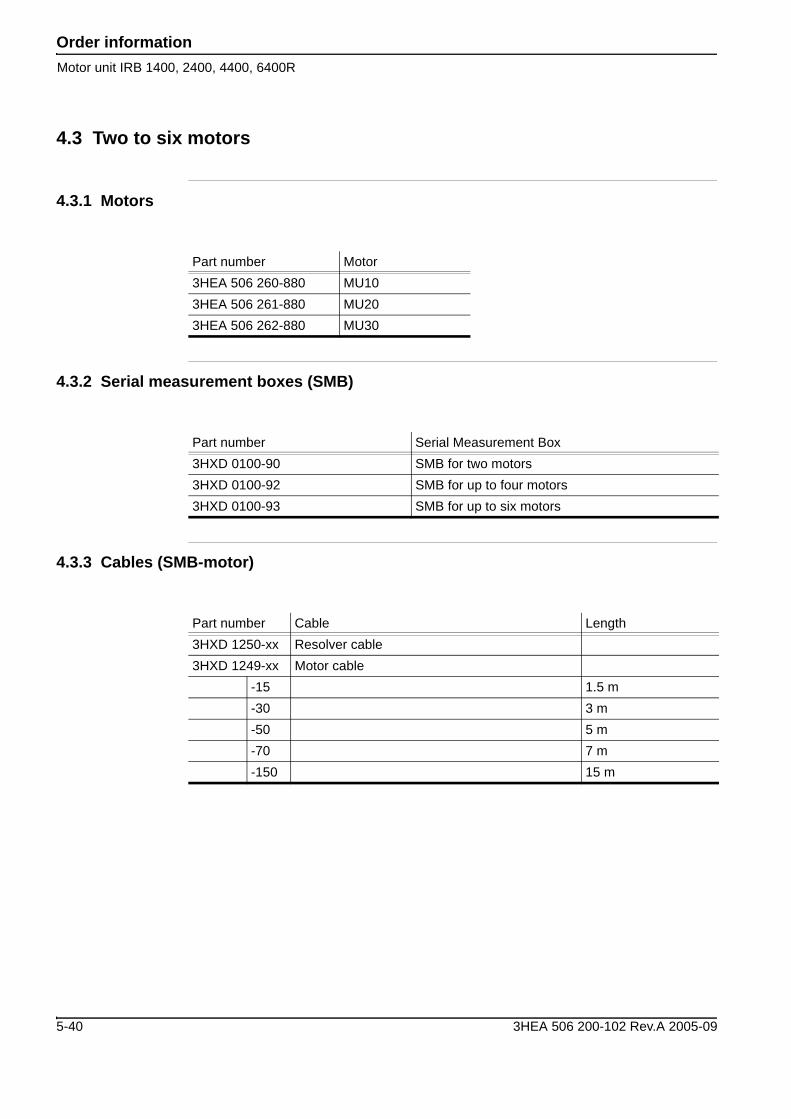
4.3 Two to six motors
4.3.1 Motors
4.3.2 Serial measurement boxes (SMB)
4.3.3 Cables (SMB-motor)
Part number Motor3HEA 506 260-880 MU103HEA 506 261-880 MU203HEA 506 262-880 MU30
Part number Serial Measurement Box3HXD 0100-90 SMB for two motors3HXD 0100-92 SMB for up to four motors3HXD 0100-93 SMB for up to six motors
Part number Cable Length3HXD 1250-xx Resolver cable3HXD 1249-xx Motor cable
-15 1.5 m-30 3 m-50 5 m-70 7 m-150 15 m
5-40 3HEA 506 200-102 Rev.A 2005-09
Order informationMotor unit IRB 6600, 7600
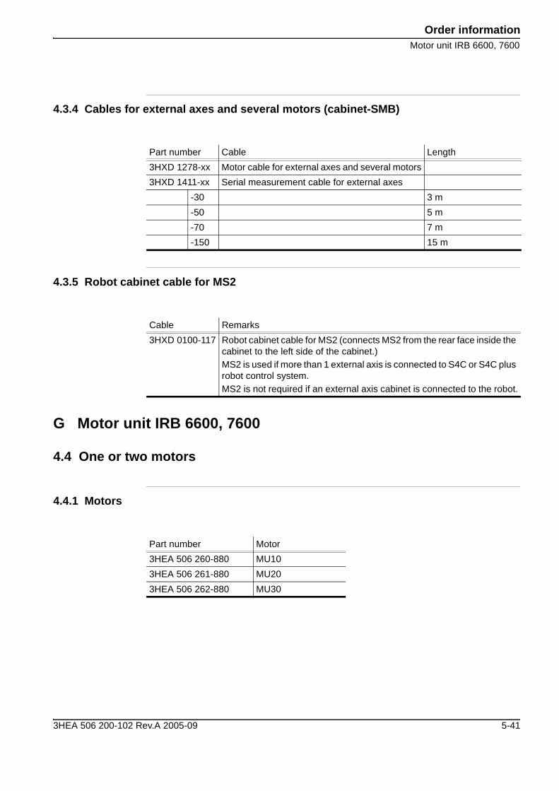
4.3.4 Cables for external axes and several motors (cabinet-SMB)
4.3.5 Robot cabinet cable for MS2
G Motor unit IRB 6600, 7600
4.4 One or two motors
4.4.1 Motors
Part number Cable Length3HXD 1278-xx Motor cable for external axes and several motors3HXD 1411-xx Serial measurement cable for external axes
-30 3 m-50 5 m-70 7 m-150 15 m
Cable Remarks3HXD 0100-117 Robot cabinet cable for MS2 (connects MS2 from the rear face inside the
cabinet to the left side of the cabinet.)MS2 is used if more than 1 external axis is connected to S4C or S4C plus robot control system.MS2 is not required if an external axis cabinet is connected to the robot.
Part number Motor3HEA 506 260-880 MU103HEA 506 261-880 MU203HEA 506 262-880 MU30
3HEA 506 200-102 Rev.A 2005-09 5-41
Order informationMotor unit IRB 6600, 7600
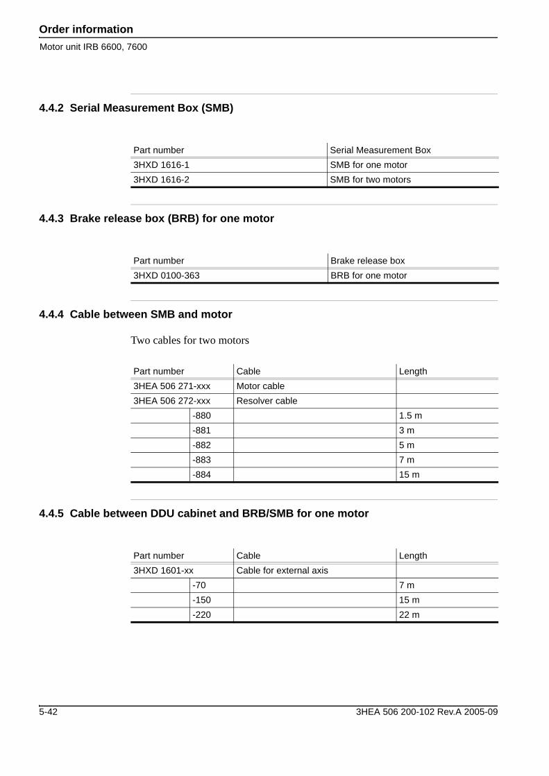
4.4.2 Serial Measurement Box (SMB)
4.4.3 Brake release box (BRB) for one motor
4.4.4 Cable between SMB and motor
Two cables for two motors
4.4.5 Cable between DDU cabinet and BRB/SMB for one motor
Part number Serial Measurement Box3HXD 1616-1 SMB for one motor3HXD 1616-2 SMB for two motors
Part number Brake release box3HXD 0100-363 BRB for one motor
Part number Cable Length3HEA 506 271-xxx Motor cable3HEA 506 272-xxx Resolver cable
-880 1.5 m-881 3 m-882 5 m-883 7 m-884 15 m
Part number Cable Length3HXD 1601-xx Cable for external axis
-70 7 m-150 15 m-220 22 m
5-42 3HEA 506 200-102 Rev.A 2005-09

Order informationMotor unit IRB 6600, 7600
4.4.6 Cable between DDU cabinet and SMB for two motors
For one or two motors
4.4.7 Cable between robot cabinet and SMB for one or two motors
4.4.8 Cable between robot and BRB
Part number Cable Length3HXD 1619-xx Cable for external axis
-70 7 m-150 15 m-220 22 m
Part number Cable Length3HXD 1618-xx Serial measurement cable for external
axis-70 7 m-150 15 m-220 22 m
Part number Cable Length3HXD 1640-xx Resolver cable for external axis
-15 1.5 m-30 3 m-50 5 m-70 7 m-150 15 m-220 22 m
3HEA 506 200-102 Rev.A 2005-09 5-43
Order informationMotor unit IRB 6600, 7600
4.5 Notes:
______________________________________________________________________________________________________________________________________________________________________________________________________________________________________________________________________________________________________________________________________________________________________________________________________________________________________________________________________________________________________________________________________________________________________________________________________________________________________________________________________________________________________________________________________________________________________________________________________________________________________________________________________________________________________________________________________________________________________________________________________________________________________________________________________________________________________________________________________________________________________________________________________________________________________________________________________________________________________________________________________________________________________________________________________________________________________________________________________________________________________________________________________________________________________________
5-44 3HEA 506 200-102 Rev.A 2005-09


3HEA 506 200-102 Rev.A 2005-09