mq power tlg-12spx whisper watt tm ac … drain plug - removing the coolant drain plug while the...
TRANSCRIPT

© C
OP
YR
IGH
T 2
001,
MU
LTIQ
UIP
IN
C.
PARTS AND OPERATION MANUAL
MULTIQUIP INC..... PARTS DEPARTMENT:18910 WILMINGTON AVE. 800-427-1244CARSON, CALIFORNIA 90746 FAX: 800-672-7877310-537-3700 SERVICE DEPARTMENT:800-421-1244 800-835-2551FAX: 310-537-3927 FAX: 310-638-8046E-mail:[email protected] • www:multiquip.com
PARTS AND OPERATION MANUAL
MQ POWERTLG-12SPX
WHISPER WATTTM
AC GENERATOR(Standard)
S/N 5107226~
Revision #4 (03/08/05)

PAGE 2 — TLG-12SPX — PARTS AND OPERATION MANUAL (STD) — REV. #4 (03/08/05)

TLG-12SPX — PARTS AND OPERATION MANUAL (STD) — REV. #4 (03/08/05) — PAGE 3
HERE'S HOW TO GET HELPPLEASE HAVE THE MODEL AND SERIAL NUMBERON-HAND WHEN CALLING
PARTS DEPARTMENT800/427-1244 or 310/537-3700FAX: 800/672-7877 or 310/637-3284
SERVICE DEPARTMENT800/835-2551 or 310/537-3700FAX: 310/638-8046
WARRANTY DEPARTMENT800/835-2551 or 310/537-3700FAX: 310/638-8046
MAIN800/421-1244 or 310/537-3700FAX: 310/537-3927

PAGE 4 — TLG-12SPX — PARTS AND OPERATION MANUAL (STD) — REV. #4 (03/08/05)
TABLE OF CONTENTS
Here's How To Get Help ............................................... 3Table Of Contents ........................................................ 4Parts Ordering Procedures .......................................... 5Rules for Safe Operation .......................................... 6-9Towing and Transportation ......................................... 10Trailer Safety Guidelines ....................................... 11-15Trailer Wiring Diagram ................................................ 16Operation and Safety Decals ................................ 17-18TLG-12SPX Specifications ...................................... 19
MQ POWER TLG-12SPXAC GENERATOR
General Information ................................................... 20Major Components .................................................... 21Dimensions ................................................................ 22Control Panel Descriptions ................................... 24-25Engine Operating/Output Terminal Panel Descriptions ...................... 26-27Output Terminal Information .................................. 28-29Installation ............................................................ 30-31Pre Setup ............................................................. 32-35Load Application ........................................................ 36Generator Start-up Procedure ................................... 37Generator Shutdown Procedure ................................. 38Maintenance ......................................................... 40-41Engine Wiring Diagram .............................................. 42Generator Wiring Diagram .......................................... 43Engine Troubleshooting ......................................... 44-45Generator/Engine Troubleshooting ............................. 46Explanation of Codes in Remarks Column ................ 48Suggested Spare Parts ............................................. 49Generator Assembly ............................................. 50-51Control Panel Assembly ....................................... 52-55Engine & Radiator Assembly ................................ 56-57Battery Assembly .................................................. 58-59Muffler Assembly .................................................. 60-61Fuel Tank Assembly .............................................. 62-63Enclosure Assembly ............................................. 64-67Rubber Seal Assembly .......................................... 68-69Name Plate And Decals ........................................ 70-71
NOTE
Specification and part numberare subject to change withoutnotice.
ISUZU 3LB1 ENGINE
Cylinder Head Cover Assembly ............................. 72-73Cylinder Head Assembly ....................................... 74-75Cylinder Block Assembly ...................................... 76-77Oil Pan & Level Gauge Assembly ......................... 78-79Camshaft & Valve Assembly ................................. 80-81Crankshaft Piston & Flywheel Assembly .............. 82-83Timing Gear & Flywheel Housing Assembly ......... 84-85Inlet Manifold Assembly ........................................ 86-87Exhaust Manifold Assembly .................................. 88-89Ventilation Assembly ............................................. 90-91Water Pump &Corrosion Resistor Assembly ......... 92-93Thermostat and Housing Assembly ...................... 94-95Fan & Fan Belt Assembly ...................................... 96-97Fuel Injection Assembly ........................................ 98-99Fuel Filter & Bracket Assembly ............................ 100-101Fuel Pump & Pipe Assembly ................................ 102-103Oil Cooler & Oil Filter Assembly ............................ 104-105Oil Pump & Oil Strainer Assembly ........................ 106-107Electrical Control Assembly .................................. 108-109Starter Comp. Assembly ....................................... 110-111Injection Pump Comp. Assembly .......................... 112-115Timing Chain X Case Assembly ............................ 116-119Air Cleaner Assembly ............................................ 120-121Switch and Relay Assembly .................................. 122-123
Terms and Condition of Sale — Parts ..................... 124

TLG-12SPX — PARTS AND OPERATION MANUAL (STD) — REV. #4 (03/08/05) — PAGE 5
PARTS ORDERING PROCEDURES
Get special freight allowanceswhen you order 10 or moreline items via FAX!**■■■■■ UPS Ground Service at no charge for freight
■■■■■ PS Third Day Service at one-half of actual freight cost
No other allowances on freight shipped by any other carrier.
**Common nuts, bolts and washers (all items under $1.00 list price)do not count towards the 10+ line items.
*DISCOUNTS ARE SUBJECT TO CHANGE*
Fax order discount and UPS special programs revised June 1, 1995
For faxed orders only
UPSSpecial
Earn Extra Discounts whenyou order by FAX!
All parts orders which include complete part numbersand are received by fax qualify for the following extradiscounts:
Number ofline items ordered Additional Discount1-9 items 3%
10+ items** 5%
Now! Direct TOLL-FREE accessto our Parts Department!
Toll-free nationwide: 800-421-1244Toll-free FAX:
800/6-PARTS-7 • 800-672-7877
■■■■■ Dealer account number■■■■■ Dealer name and address■■■■■ Shipping address (if different than billing address)■■■■■ Return fax number■■■■■ Applicable model number■■■■■ Quantity, part number and description of each part■■■■■ Specify preferred method of shipment:
• UPS Ground
• UPS Second Day or Third Day*
• UPS Next Day*
• Federal Express Priority One (please provide us with your FederalExpress account number)*
• Airborne Express*
• Truck or parcel post
*Normally shipped the same day the order is received, if prior to 2PM west coast time.
Extra Fax Discount
Extra Fax Discount
Extra Fax Discount
Extra Fax Discount
Extra Fax Discount
for Domestic USAfor Domestic USAfor Domestic USAfor Domestic USA
for Domestic USA
Dealers OnlyDealers OnlyDealers OnlyDealers OnlyDealers Only

PAGE 6 — TLG-12SPX — PARTS AND OPERATION MANUAL (STD) — REV. #4 (03/08/05)
RULES FOR SAFE OPERATION
■ NEVER touch the hot exhaustmanifold, muffler or cylinder. Allowthese parts to cool before servicingengine or generator.
■ The engine of this generator requires an adequate freeflow of cooling air. Never operate the generator in anyenclosed or narrow area where free flow of the air is
restricted. If the air flowis restricted it will causeserious damage to thegenerator or engine andmay cause injury topeople. The generatorengine gives off DEADLYcarbon monoxide gas.
■ High Temperatures – Allow the engine to cool beforeadding fuel or performing service and maintenancefunctions. Contact with hot components can cause seriousburns.
Failure to follow instructions in this manualmay lead to serious injury or even death!This equipment is to be operated by trainedand qualified personnel only! This equipmentis for industrial use only.
The following safety guidelines should always be used whenoperating the TLG-12SPX portable generator:
GENERAL SAFETY
■ DO NOT operate or service this equipment beforereading this entire manual.
■ This equipment should not be operated bypersons under 18 years of age.
■ NEVER operate this equipment without properprotective clothing, shatterproof glasses, steel-toed boots and other protective devicesrequired by the job.
■ NEVER operate this equipment when not feelingwell due to fatigue, illness or taking medicine.
■ NEVER operate this equipment under theinfluence or drugs or alcohol.
■ NEVER use accessories or attachments, which are notrecommended by MQ Power for this equipment. Damageto the equipment and/or injury to user may result.
■ Manufacturer does not assume responsibility for anyaccident due to equipment modifications.
■ Whenever necessary, replace nameplate, operation andsafety decals when they become difficult read.
■ Always check the machine for loosened threads or boltsbefore starting.
■ Be sure the generator is on secure level ground so that itcannot slide or shift around, endangering workers. Alsokeep the immediate area free of all bystanders.
CAUTIONCAUTIONCAUTIONCAUTIONCAUTION:
■ Always use extreme caution whenworking with flammable liquids. Whenrefueling, stop the engine and allow itto cool. DO NOT smoke around or nearthe machine. Fire or explosion couldresult from fuel vapors, or if fuel is spilledon a hot engine.
■ NEVER operate the generator in anexplosive atmosphere or near combustiblematerials. An explosion or fire could resultcausing severe bodily harm or evendeath.
■ Topping-off to fil ler por t isdangerous, as it tends to spill fuel.
Always refuel in a well-ventilated area,away from sparks and open flames.
CAUTION:CAUTION:CAUTION:CAUTION:CAUTION:

TLG-12SPX — PARTS AND OPERATION MANUAL (STD) — REV. #4 (03/08/05) — PAGE 7
RULES FOR SAFE OPERATION
CAUTIONCAUTIONCAUTIONCAUTIONCAUTION:
■ Backfeed to a utility system can cause electrocutionand/or property damage. Do not connect to anybuilding's electrical system except through an approveddevice or after building main switch is opened.
■ Never use damaged or worn cables when connectingpower tools or equipment to the generator. Make surepower connecting cables are securely connected to thegenerator’s output terminals, insufficient tightening of theterminal connections may cause damage to the generatorand electrical shock.
CAUTIONCAUTIONCAUTIONCAUTIONCAUTION:DO NOT touch or open any of the belowmentioned components while thegenerator is running. Always allowsufficient time for the engine and generatorto cool before performing maintenance.
Radiator
1. Radiator Cap - Removing the radiator cap while theengine is hot will result in high pressurized, boiling waterto gush out of the radiator, causing severe scalding toany persons in the general area of the generator.
2. Coolant Drain Plug - Removing the coolant drain plugwhile the engine is hot will result in hot coolant to gushout of the coolant drain plug, therefore causing severescalding to any persons in the general area of thegenerator.
3. Engine Oil Drain Plug - Removing the engine oil drainplug while the engine is hot will result in hot oil to gushout of the oil drain plug, therefore causing severescalding to any persons in the general area of thegenerator.
CAUTIONCAUTIONCAUTIONCAUTIONCAUTION:
CAUTIONCAUTIONCAUTIONCAUTIONCAUTION:
■ NEVER touch output terminals during operation. This isextremely dangerous. Always stop the machine whencontact with the output terminals is required.

PAGE 8 — TLG-12SPX — PARTS AND OPERATION MANUAL (STD) — REV. #4 (03/08/05)
RULES FOR SAFE OPERATION
■ NEVER Run engine without air filter. Severe enginedamage may occur.
■ Always service air cleaner frequently to prevent carburetormalfunction.
■ Always disconnect the battery before performing serviceon the generator.
■ Always be sure the operator is familiar with proper safetyprecaution s and operations techniques before usinggenerator.
■ Always store equipment properly when not in use.Equipment should be stored in a clean, dry location out ofthe reach of children.
■ DO NOT leave the generator running in the manual modeunattended.
■ DO NOT allow unauthorized people to operate thisequipment.
■ Always read, understand, and follow procedures inOperator’s Manual before attempting to operate equipment.
■ Refer to the Isuzu Engine Operator’s Manual for enginetechnical questions or information.
Loading and Unloading (Crane)
■ Before lifting, make sure the generator's lifting hook issecure and that there is no apparent damage to thegenerator itself (loose screws, nuts and bolts). If anypart is loose or damaged, please take corrective actionbefore lifting.
■ Always drain fuel prior to lifting.
■ Always make sure crane or lifting device has beenproperly secured to the hook of guard frame on generator.
■ NEVER lift the machine while the engine is running.
■ Use adequate lifting cable (wire or rope) of sufficientstrength.
■ When lifting the generator, always use the balancedcenter-point suspension hook and lift straight upwards.
■ NEVER allow any person or animal to stand underneaththe machine while lifting.
■ When loading the generator on a truck, be sure to usethe front and back frame bars as a means to secure thegenerator during transport.
Battery
Never over fill the battery with water abovethe upper limit.
CAUTIONCAUTIONCAUTIONCAUTIONCAUTION:
The battery contains acids that can cause injury to the eyesand skin. To avoid eye irritation, always wear safety glasses.Use well insulated gloves when picking up the battery. Usethe following guidelines when handling the battery:
1. DO NOT drop the battery. There is the possibility of riskthat the battery may explode.
2. DO NOT expose the battery to open flames, sparks,cigarettes etc. The battery contains combustible gasesand liquids. If these gases and liquids come in contactwith a flame or spark, an explosion could occur.
3. Always keep the battery charged. If the battery is notcharged a buildup of combustible gas will occur.
4. Always keep battery charging and booster cables in goodworking condition. Repair or replace all worn cables.
5. Always recharge the battery in an open air environment,to avoid risk of a dangerous concentration of combustiblegases.
6. In case the battery liquid (dilute sulfuric acid) comes incontact with clothing or skin, rinse skin or clothingimmediately with plenty of water.
7. In case the battery liquid (dilute sulfuric acid) comes incontact with your eyes, rinse eyes immediately withplenty of water, then contact the nearest doctor or hospital,and seek medical attention.

TLG-12SPX — PARTS AND OPERATION MANUAL (STD) — REV. #4 (03/08/05) — PAGE 9
Transporting■ Always shutdown engine before transporting.
■ Tighten fuel tank cap securely.
■ Drain fuel when transporting generator over long distancesor bad roads.
■ Always tie-down the generator during transportation bysecuring the generator.
■ If generator is mounted on a trailer, make sure trailercomplies with all local and state safety transportationlaws. See page 10 for basic towing procedures.
Emergencies
■ Always know the location of the nearest fire extinguisherand first aid kit. Know the location of the nearest telephone.Also know the phone numbers of the nearest ambulance,doctor and fire department.
RULES FOR SAFE OPERATION
Maintenance Safety■ NEVER lubricate components or attempt service on a
running machine.
■ Always allow the machine a proper amount of time tocool before servicing.
■ Keep the machinery in proper running condition.
■ Fix damage to the machine immediately and alwaysreplace broken parts.
■ Dispose of hazardous waste properly. Examples ofpotentially hazardous waste are used motor oil, coolant,fuel, and fuel filters.
■ DO NOT use plastic containers to dispose of hazardouswaste.
■ DO NOT pour waste, oil, coolant or fuel directly onto theground, down a drain or into any water source.

PAGE 10 — TLG-12SPX — PARTS AND OPERATION MANUAL (STD) — REV. #4 (03/08/05)
To reduce the possibility of an accidentwhile transporting the generator on public roads, alwaysmake sure the trailer (Figure 1) that supports the generatorand the towing vehicle are in good operating condition andboth units are mechanically sound.
The following list of suggestions should be used when towingyour generator:
CAUTION :CAUTION :CAUTION :CAUTION :CAUTION :Towing Safety Precautions
Check with your county or state safetytowing regulations department before towingyour generator.
■ Make sure the hitch and coupling of the towing vehicleare rated equal to, or greater than the trailer "gross vehicleweight rating" (GVWR).
■ ALWAYS inspect the hitch and coupling for wear. NEVERtow a trailer with defective hitches, couplings, chainsetc.
■ Check the tire air pressure on both towing vehicle andtrailer. Also check the tire tread wear on both vehicles.
■ ALWAYS make sure the trailer is equipped with a "SafetyChain".
TLG-12SPX — TOWING RULES FOR SAFE OPERATION
■ ALWAYS attach trailer’s safety chain to bumper of towingvehicle.
■ ALWAYS make sure the vehicle and trailer directional,backup, brake, and trailer lights are connected andworking properly.
■ The maximum speed for highway towing is 45 MPHunless posted otherwise. Recommended off-road towingis not to exceed 10 MPH or less depending on type ofterrain.
■ Place chocked blocks underneath wheel to preventrolling, while parked.
■ Place support blocks underneath the trailer’s bumper toprevent tipping, while parked.
■ Use the trailer’s hand winch to adjust the height of thetrailer, then insert locking pin to lock wheel stand in place,while parked.
■ Avoid sudden stops and starts. This can cause skidding,or jackknifing. Smooth, gradual starts and stops willimprove gas milage.
■ Avoid sharp turns to prevent rolling.
■ Remove wheel stand when transporting.
■ DO NOT transport generator with fuel in tank.
Figure 1. Generator with Trailer
TLG-12SPX — PARTS AND OPERATION MANUAL (STD) — REV. #4 (03/08/05) — PAGE 11
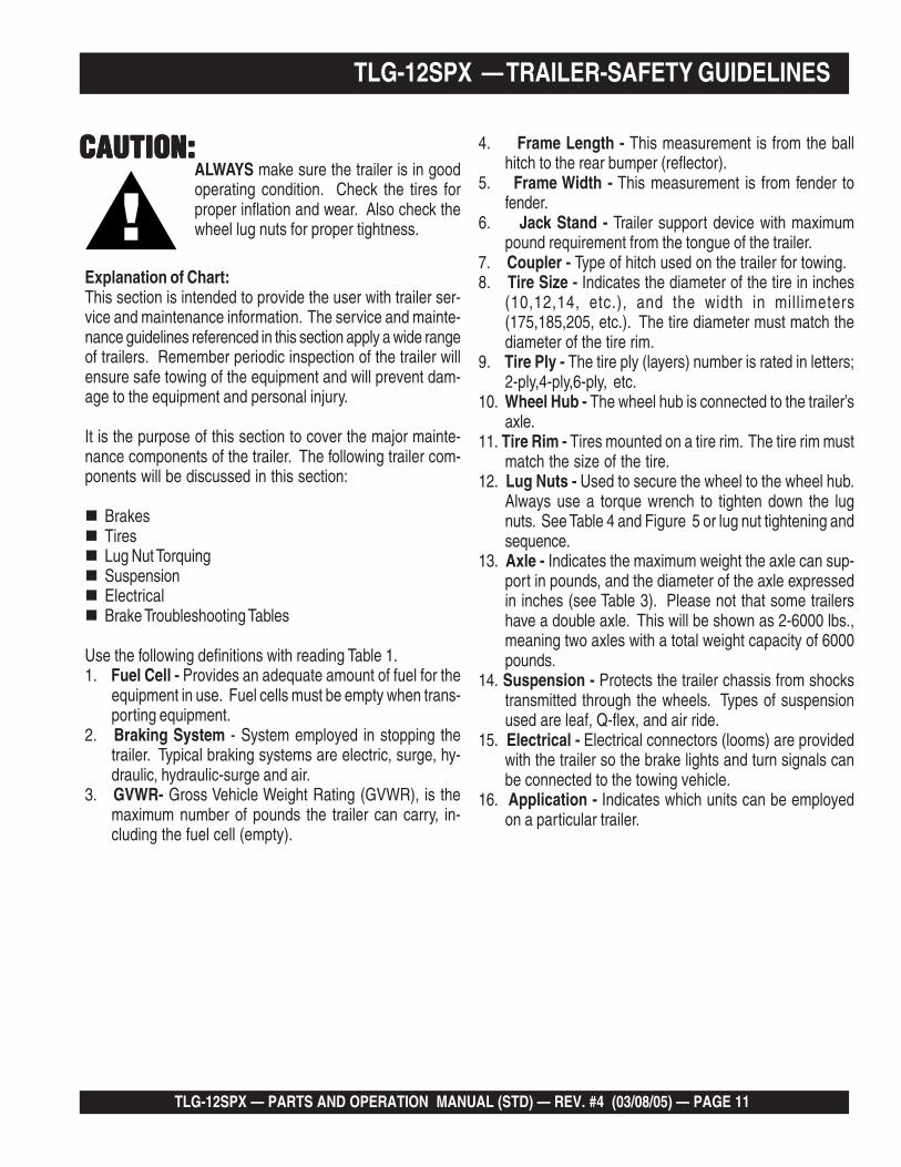
Explanation of Chart:This section is intended to provide the user with trailer ser-vice and maintenance information. The service and mainte-nance guidelines referenced in this section apply a wide rangeof trailers. Remember periodic inspection of the trailer willensure safe towing of the equipment and will prevent dam-age to the equipment and personal injury.
It is the purpose of this section to cover the major mainte-nance components of the trailer. The following trailer com-ponents will be discussed in this section:
BrakesTiresLug Nut TorquingSuspensionElectricalBrake Troubleshooting Tables
Use the following definitions with reading Table 1.1. Fuel Cell - Provides an adequate amount of fuel for the
equipment in use. Fuel cells must be empty when trans-porting equipment.
2. Braking System - System employed in stopping thetrailer. Typical braking systems are electric, surge, hy-draulic, hydraulic-surge and air.
3. GVWR- Gross Vehicle Weight Rating (GVWR), is themaximum number of pounds the trailer can carry, in-cluding the fuel cell (empty).
TLG-12SPX — TRAILER-SAFETY GUIDELINES
4. Frame Length - This measurement is from the ballhitch to the rear bumper (reflector).
5. Frame Width - This measurement is from fender tofender.
6. Jack Stand - Trailer support device with maximumpound requirement from the tongue of the trailer.
7. Coupler - Type of hitch used on the trailer for towing.8. Tire Size - Indicates the diameter of the tire in inches
(10,12,14, etc.), and the width in millimeters(175,185,205, etc.). The tire diameter must match thediameter of the tire rim.
9. Tire Ply - The tire ply (layers) number is rated in letters;2-ply,4-ply,6-ply, etc.
10. Wheel Hub - The wheel hub is connected to the trailer’saxle.
11. Tire Rim - Tires mounted on a tire rim. The tire rim mustmatch the size of the tire.
12. Lug Nuts - Used to secure the wheel to the wheel hub.Always use a torque wrench to tighten down the lugnuts. See Table 4 and Figure 5 or lug nut tightening andsequence.
13. Axle - Indicates the maximum weight the axle can sup-port in pounds, and the diameter of the axle expressedin inches (see Table 3). Please not that some trailershave a double axle. This will be shown as 2-6000 lbs.,meaning two axles with a total weight capacity of 6000pounds.
14. Suspension - Protects the trailer chassis from shockstransmitted through the wheels. Types of suspensionused are leaf, Q-flex, and air ride.
15. Electrical - Electrical connectors (looms) are providedwith the trailer so the brake lights and turn signals canbe connected to the towing vehicle.
16. Application - Indicates which units can be employedon a particular trailer.
CAUTION:CAUTION:CAUTION:CAUTION:CAUTION:ALWAYS make sure the trailer is in goodoperating condition. Check the tires forproper inflation and wear. Also check thewheel lug nuts for proper tightness.

PAGE 12 — TLG-12SPX — PARTS AND OPERATION MANUAL (STD) — REV. #4 (03/08/05)
snoitacificepS.1elbaT
LEDOM NOITACILPPA LEUFLLEC
EKARBMETSYS
RWVG EMARFHTGNEL
EMARFHTDIW
KCAJDNATS
W01-RLRT ,522WDS003WLT,052WGS
ON ON SBL0091 "69 "05 .BL008LEEHWTLITLLUF
01-RLRT ,21GLT,01ACD51-ACD
ON ON SBL0091 "69 "05 .BL008LEEHWTLITLLUF
FX01-RLRT ,21-GLT,01ACD003-WLT,51ACD
LAG25 ON SBL0091 "69 "05 .BL008LEEHWTLITLLUF
W522-RLRT ,SREDLEWSS0007AD
ON ON SBL0022 "58 "24 .BL008LEEHWTLITLLUF
004WLB-RLRT 004-WLB ON CIRTCELE SBL0072 "451TSAM/W"421O/W
"55)LLAT"87(
.BL008LEEHWTLITLLUF
X05-RLRT 52-ACD ON ON SBL0072 "421 "55 .BL008LEEHWTLITLLUF
FX05-RLRT 52-ACD LAG14 ON SBL0072 "421 "55 .BL008LEEHWTLITLLUF
W07-RLRT 07,06-,54-ACD ON EGRUS SBL0007 "681 "77 .BL0002DAPTALF
X07-RLRT 07,06-,54-ACD TPO EGRUS SBL0007 "831 "66 .BL0002DAPTALF
FX07-RLRT 07,06-,54-ACD LAG35 EGRUS SBL0007 "831 "66 .BL0002DAPTALF
FX001-RLRT 521,001-ACD LAG051 EGRUSCILUARDYH SBL0007 "091 "67 .BL0002DAPTALF
521/58-RLRT ,001,58-ACD521
LAG541 CILUARDYH SBL00001 "681 "77 .BL0002DAPTALF
FX051-RLRT 081,051-ACD LAG002 EGRUSCILUARDYH SBL06111 "402 "48 .BL0005DAPTALF
FX022-RLRT 022-ACD LAG052 EGRUSCILUARDYH SBL00041 "222 "38 .BL0005DAPTALF
FX003-RLRT 003-ACD LAG052 EGRUSCILUARDYH SBL00081 "832 "38 .BL0005DAPTALF
FX004-RLRT 004-ACD LAG053 CIRTCELE SBL00081 "832 "38 .BL0005DAPTALF
FX006-RLRT 008,006-ACD LAG055 RIA SBL00003 "483 "69 .BL0005DAPTALF
XS008-RLRT 008,006-ACD LAG055 RIA SBL00003 "483 "69 .BL0005DAPTALF
TLG-12SPX —TRAILER-SPECIFICATIONS
TLG-12SPX — PARTS AND OPERATION MANUAL (STD) — REV. #4 (03/08/05) — PAGE 13
)t'noC(snoitacificepS.1elbaT
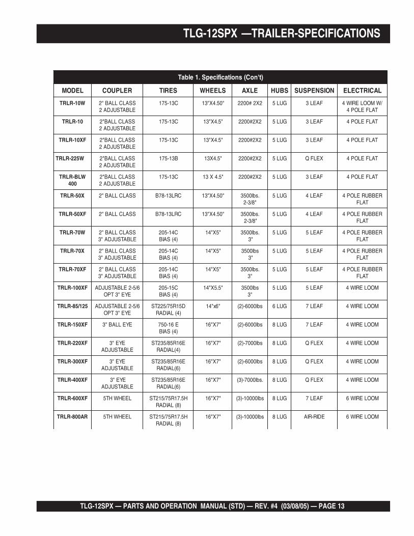
LEDOM RELPUOC SERIT SLEEHW ELXA SBUH NOISNEPSUS LACIRTCELE
W01-RLRT SSALCLLAB"2ELBATSUJDA2
C31-571 "05.4X"31 2X2#0022 GUL5 FAEL3 /WMOOLERIW4TALFELOP4
01-RLRT SSALCLLAB"2ELBATSUJDA2
C31-571 "5.4X"31 2X2#0022 GUL5 FAEL3 TALFELOP4
FX01-RLRT SSALCLLAB"2ELBATSUJDA2
C31-571 "5.4X"31 2X2#0022 GUL5 FAEL3 TALFELOP4
W522-RLRT SSALCLLAB"2ELBATSUJDA2
B31-571 "5.4X31 2X2#0022 GUL5 XELFQ TALFELOP4
WLB-RLRT004
SSALCLLAB"2ELBATSUJDA2
C31-571 "5.4X31 2X2#0022 GUL5 FAEL3 TALFELOP4
X05-RLRT SSALCLLAB"2 CRL31-87B "05.4X"31 .sbl0053"8/3-2
GUL5 FAEL4 REBBURELOP4TALF
FX05-RLRT SSALCLLAB"2 CRL31-87B "05.4X"31 .sbl0053"8/3-2
GUL5 FAEL4 REBBURELOP4TALF
W07-RLRT SSALCLLAB"2ELBATSUJDA"3
C41-502)4(SAIB
"5X"41 .sbl0053"3
GUL5 FAEL5 REBBURELOP4TALF
X07-RLRT SSALCLLAB"2ELBATSUJDA"3
C41-502)4(SAIB
"5X"41 sbl0053"3
GUL5 FAEL5 REBBURELOP4TALF
FX07-RLRT SSALCLLAB"2ELBATSUJDA"3
C41-502)4(SAIB
"5X"41 .sbl0053"3
GUL5 FAEL5 REBBURELOP4TALF
FX001-RLRT 6/5-2ELBATSUJDAEYE"3TPO
C51-502)4(SAIB
"5.5X"41 sbl0053"3
GUL5 FAEL5 MOOLERIW4
521/58-RLRT 6/5-2ELBATSUJDAEYE"3TPO
D51R57/522TS)4(LAIDAR
"6x"41 sbl0006-)2( GUL6 FAEL7 MOOLERIW4
FX051-RLRT EYELLAB"3 E61-057)4(SAIB
"7X"61 sbl0006-)2( GUL8 FAEL7 MOOLERIW4
FX022-RLRT EYE"3ELBATSUJDA
E61R58/532TS)4(LAIDAR
"7X"61 sbl0007-)2( GUL8 XELFQ MOOLERIW4
FX003-RLRT EYE"3ELBATSUJDA
E61R58/532TS)6(LAIDAR
"7X"61 sbl0006-)2( GUL8 XELFQ MOOLERIW4
FX004-RLRT EYE"3ELBATSUJDA
E61R58/532TS)6(LAIDAR
"7X"61 .sbl0007-)3( GUL8 XELFQ MOOLERIW4
FX006-RLRT LEEHWHT5 H5.71R57/512TS)8(LAIDAR
"7X"61 sbl00001-)3( GUL8 FAEL7 MOOLERIW6
RA008-RLRT LEEHWHT5 H5.71R57/512TS)8(LAIDAR
"7X"61 sbl00001-)3( GUL8 EDIR-RIA MOOLERIW6
TLG-12SPX —TRAILER-SPECIFICATIONS

PAGE 14 — TLG-12SPX — PARTS AND OPERATION MANUAL (STD) — REV. #4 (03/08/05)
Tires/Wheels/Lug NutsTires and wheels are a very important and criticalcomponents of the trailer. When specifying or replacing thetrailer wheels it is important the wheels, tires, and axle areproperly matched.
CAUTION:DO NOT attempt to repair or modify awheel. DO NOT install in inner tube tocorrect a leak through the rim. If the rimis cracked, theair pressure inthe inner tube
may cause pieces of the rim toexplode (break off) with great forceand cause serious eye or bodilyinjury.
Tire Wear/InflationTire inflation pressure is the most important factor in tire life.Pressure should be checked cold before operation DO NOTbleed air from tires when they are hot. Check inflationpressure weekly during use to insure the maximum tire lifeand tread wear.Table 2 (Tire Wear Troubleshooting) will help pinpoint thecauses and solutions of tire wear problems.
CAUTION:
NOTE
ALWAYS wear safety glasses when removingor installing force fitted parts. Failure to complymay result in serious injury.
SuspensionThe leaf suspension springs and associated components(Figure 2) should be visually inspected every 6,000 miles forsigns of excessive wear, elongation of bolt holes, andloosening of fasteners. Replace all damaged parts(suspension) immediately. Torqued suspension componentsas detailed in Table 3.
TLG-12SPX —TRAILER SAFETY GUIDELINES
Figure 2. Major Suspension Components

TLG-12SPX — PARTS AND OPERATION MANUAL (STD) — REV. #4 (03/08/05) — PAGE 15
stnemeriuqeReuqroTnoisnepsuS.3elbaT
metI ).sbL-.tF(euqroT
TLOB-U"8/3 53-XAM03-NIM
TLOB-U"61/7 06-XAM54-NIM
TLOB-U"2/1 06-XAM54-NIM
SHACKLE BOLT
SPRING EYE BOLT
SNUG FIT ONLY. PARTS MUST ROTATE FREELY.LOCKING NUTS OR COTTER PINS ARE PROVIDED TO
RETAIN NUT-BOLT ASSEMBLY.
SHOULDER TYPE
SHACKLE BOLT
05-XAM03-NIM
stnemeriuqeReuqroTeriT.4elbaT
eziSleehW ssaPtsriFSBL-TF
ssaPdnoceSSBL-TF
ssaPdrihTSBL-TF
"21 52-02 04-53 56-05
"31 52-02 04-53 56-05
"41 52-02 06-05 021-09
"51 52-02 06-05 021-09
"61 52-02 06-05 021-09
Lug Nut Torque RequirementsIt is extremely important to apply and maintain proper wheelmounting torque on the trailer. Be sure to use only thefasteners matched to the cone angle of the wheel. Properprocedure for attachment of the wheels is as follows:
1. Start all wheel lug nuts by hand.2. Torque all lug nuts in sequence. See Figure 3. DO NOT
torque the wheel lug nuts all the way down. Tighteneach lug nut in 3 separate passes as defined by Table 4.
3. After first road use, retorque all lug nuts in sequence.Check all wheel lug nuts periodically.
NOTE
NEVER use an pneumatic air gun totighten wheel lug nuts.
TLG-12SPX —TRAILER SAFETY GUIDELINES
Figure 3. Wheel Lug Nuts Tightening Sequence
PAGE 16 — TLG-12SPX — PARTS AND OPERATION MANUAL (STD) — REV. #4 (03/08/05)
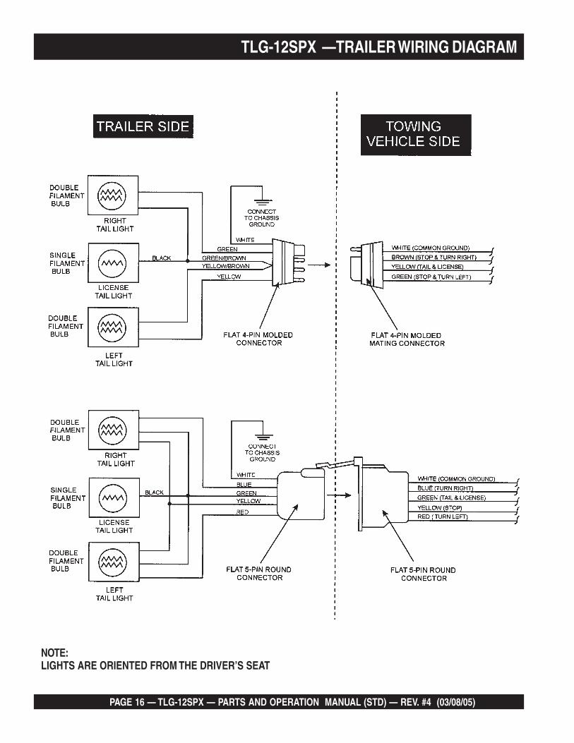
NOTE:LIGHTS ARE ORIENTED FROM THE DRIVER’S SEAT
TLG-12SPX —TRAILER WIRING DIAGRAM

TLG-12SPX — PARTS AND OPERATION MANUAL (STD) — REV. #4 (03/08/05) — PAGE 17
TLG-12SPX — GENERATOR DECALS
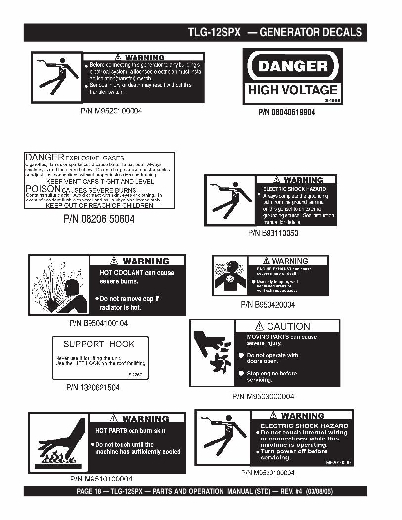
The TLG-12SPX generator is equipped with a number of safety decals. These decals are provided for operator safetyand maintenance information. The illustration below and on the preceding pages show the decals as they appear on themachine. Should any of these decals become unreadable, replacements can be obtained from your dealer.
PAGE 18 — TLG-12SPX — PARTS AND OPERATION MANUAL (STD) — REV. #4 (03/08/05)
TLG-12SPX — GENERATOR DECALS

TLG-12SPX — PARTS AND OPERATION MANUAL (STD) — REV. #4 (03/08/05) — PAGE 19
TLG-12SPX — SPECIFICATIONS
snoitacificepS.5elbaT
snoitacificepSrotareneG
ledoM XPS21-GLT
epyT rotareneggniraebelgnis,foorppird,detalitnevfles,dleifgnivloveR
noitcennoCerutamrA seireS
tuptuOybdnatS WK31
tuptuOemirP WK21
egatloV V084roV042
ycneuqerF zH06
deepS mpr0063
rotcaFrewoP 1
rewoPCA.xuA zH06,esahPelgniS
egatloV V042/021
)A(BdleveldnuoSteef32daollluF 76
snoitacificepSenignE
ledoM 1BL3uzusI
epyT rebmahclriws,delooc-retaw,elcyC4
srednilyCfo.oN srednilyc3
ekortSxeroB )mm08xmm77(.ni1.3x.ni0.3
tuptuOdetaR mpr0063/PH22
tnemecalpsiD )cc4211(.ni.uc86
gnitratS cirtcelE
yticapaCtnalooC )sretil4.3(.lag9.0
yticapaCliOebuL )sretil5.4(.lag2.1
noitpmusnoCleuFtarh/)L3.5(.lag4.1 daollluf tarh/)L5.4(.lag2.1 daol4/3
tarh/)L7.3(.lag0.1 daol2/1 tarh/)L0.3(.lag8.0 daol4/1
yrettaB 1xhA07-V21
leuF leuFleseiD2#

PAGE 20 — TLG-12SPX — PARTS AND OPERATION MANUAL (STD) — REV. #4 (03/08/05)
TLG-12SPX — GENERAL INFORMATION
TLG-12SPX FAMILIARIZATION
Generator
The MQ Power Model TLG-12SPX is a 9.6 kW generatorthat is designed as a high quality portable power source fortelecom sites, lighting facilities, power tools, submersiblepumps and other industrial and construction machinery.
Control Panel
The “Control Panel” is provided with the following:
Engine Speed Switch Indicator panel
Output Voltage Adjustment KnobFrequency Meter (Hz)AC Ammeter (Amps)AC Voltmeter (Volts)Main Circuit Breaker 50 amps
Output Terminal Panel
The “Output Terminal Panel” is provided with the following:
One 120/240V output receptacle, 50 ampTwo 120V input receptacles, 20 amp and 30 amp One 240V input receptacle, 30amp
Engine
The TLG-12SPX is powered by a 4 cycle, water cooled,Isuzu 3LB1 diesel engine. This engine is designed to meetevery performance requirement for the generator. ReferenceTable 5, page 19 for engine specifications.
In keeping with Multiquip's policy of constantly improvingits products, the specifications quoted herein are subject tochange without prior notice.
The basic controls and indicators for the TLG-12SPXgenerator are addressed on the following pages.
Mechanical Governor SystemThe mechanical governor system control the RPM of theengine. When the engine demands increase or decrease,the mechanical governor system regulates the frequencyvariation to ±1.5%. The electronic governor option in-creases frequency variation to ±.25%.
Open Delta Excitation System
The TLG-12SPX generator is equipped with the state of theart "Open-Delta" excitation system. The open delta systemconsist of an electrically independent winding wound amongstationary windings of the AC output section.
There are four leads: A, B, C and D. During light loads, thepower to the Automatic Voltage Regulator (AVR) is suppliedfrom the leads parallel connections of B&C. When loadsincrease, the AVR switches and accepts power from leadsA&D. The output of leads A&D increase proportionally withload. This of adding the voltages to each phase providesbetter voltage response during heavy loads.
The connections of the AVR to the AC output windings arefor sensing only. No power is required from these windings.
The open-delta design provides virtually unlimited excitationcurrent, offering maximum motor starting capabilities. Theexcitation does not have a "fixed ceiling" and respondsaccording the demands of the required load.

TLG-12SPX — PARTS AND OPERATION MANUAL (STD) — REV. #4 (03/08/05) — PAGE 21
TLG-12SPX — MAJOR COMPONENTS
Figure 4. Major Components

PAGE 22 — TLG-12SPX — PARTS AND OPERATION MANUAL (STD) — REV. #4 (03/08/05)
TLG-12SPX — DIMENSIONS (TOP, SIDE AND FRONT)
Figure 5. Dimensions

TLG-12SPX — PARTS AND OPERATION MANUAL (STD) — REV. #4 (03/08/05) — PAGE 23
NOTE PAGE

PAGE 24 — TLG-12SPX — PARTS AND OPERATION MANUAL (STD) — REV. #4 (03/08/05)
TLG-12SPX — CONTROL PANEL
Figure 6. Control Panel

TLG-12SPX — PARTS AND OPERATION MANUAL (STD) — REV. #4 (03/08/05) — PAGE 25
TLG-12SPX — CONTROL PANEL
The definitions below describe the controls and functions ofthe TLG-12SPX "Control Panel " (Figure 6).
1. Circuit Breaker – This three-pole, 65 amp breaker isprovided to protect the UNV voltage output terminalsfrom overload.
2. Frequency Meter – Indicates the output frequency inhertz (Hz). Normally 60 Hz ±1 Hz .
3. AC Voltmeter – Indicates the single phase outputvoltage present at the UNV terminals.
4. AC Ammeter – Indicates the amount of current theload is drawing from the generator.
5. Indicator Lamp - This engine waring indicator will notifypossible damage before it occurs:
A. Oil Pressure - the light will go on during initialstart, but will go out once the engine is warm. If theoil pressure light comes on during operation, this mayindicate critical low oil level.
B. Charge Light - This light indicates the battery isnot charging.
C. Water Temperature Light - This light indicates thecoolant temperature is abnormally high.
D. Engine Protection - This will shut down the engineif there is an abnormal event that may have occurred.This prevents damage to the engine.
6. Starter Switch - This is to turn on and off the enginewith a key.
7. Hour Meter - This indicates the amount of time thegenerator has been running.
8. Voltage Regulator Control – Allows manual adjustmentof the generator output voltage.

PAGE 26 — TLG-12SPX — PARTS AND OPERATION MANUAL (STD) — REV. #4 (03/08/05)
TLG-12SPX — ENGINE OPERATING/OUTPUT TERMINAL PANEL
Figure 7. Engine Control/ Output Terminal Panel

TLG-12SPX — PARTS AND OPERATION MANUAL (STD) — REV. #4 (03/08/05) — PAGE 27
TLG-12SPX — ENGINE OPERATING/OUTPUT TERMINAL PANEL
The definitions below describe the controls and functions ofthe TLG-12SPX " Engine Operating/Output TerminalPanel” (Figure 7).
1. Idle Control Switch - This switch is used to changethe idle of the engine from low to high (on somemodels)
2. Throttle Handle - This handle is used forinitial start up of the engine.
3. GFCI Receptacle - This is a 20A, 120Vparallel slot with a U-ground.
4. NEMA receptacle - These output receptacles arelocking type. Both are 30 amps, one is120V, the other 240V.
5. NEMA CS-6369 receptacle - This lockingtype output receptacle is a 50 amp, 120/240V.

PAGE 28 — TLG-12SPX — PARTS AND OPERATION MANUAL (STD) — REV. #4 (03/08/05)
TLG-12SPX FAMILIARIZATION
The Output Terminal panel is provided with the following:One GFCI 120 Volt Receptacle, 20 Amp (single-phase)Ground Terminal (for GFCI receptacle)Main Circuit Breaker 50 ampsGFCI Circuit Breaker 20 ampsNEMA L530R Output ReceptacleNEMA L630R Output ReceptacleNEMA CS6369 Output Receptacle
Output Terminal Panel
The Output Control Panel (See Figure 6) is located on therear (Control Panel) end of the generator. The UNV lugs areprotected by a face plate cover that can be secured in theclose position by a 6mm bolt (See Figure 7).
120 Volt ReceptacleOne GFCI Duplex Nema 5-20R (120V, 20 Amp) receptacleis provided on the output terminal. This receptacle can beused anytime the generator is in operation. The receptacleis controlled by the circuit breaker located on the controlpanel.
Pressing the reset button will reset the GCFI receptacle if itis tripped. Pressing the "Test Button" (See Figure 2) in thecenter of this receptacle will check the GFCI function. Thereceptacle should be tested at least once a month.
Figure 9. GFCI TestButton
Figure 8. Retaining Bolt
NEMA L5-30R Output ReceptacleThe L5-30R receptacle supplies 30 amps at 120 volts. A 30amp circuit breaker helps protect any load being used.
NEMA L6-30R Output ReceptacleThe L6-30R is a receptacle that supplies 30 amps at 240volts. The 30 amp circuit breaker helps protect any loadbeing used.
NEMA CS-6369 Output Receptacle
The CS-6369 is a receptacle that supplies 50 amps at 120/240 volts. A 50 amp circuit breaker helps protect any loadbeing used. See Figure 12 for details.
Connecting LoadLoads are to be connected to the generator by thereceptacles supplied. Make sure to read the operationmanual before attempting to connect a load to the generator.
Maximum OutputThe entire load connected to the UNV Lugs and both slots inthe duplex receptacle must not exceed 13 kW in standby or 12kW in prime output.
Output Terminal Panel Available VoltagesThe TLG12SPX is a single phase generator only. It is ableto supply both 120 volt and 240 volt.
Maximum AmpsThe generator unit provides 50 amps of power. Do notexceed the maximum amps!
When using plural single phasevoltages, make sure to balancethe load on each of the singlephase legs.
NOTE
TLG-12SPX — OUTPUT TERMINAL PANEL

TLG-12SPX — PARTS AND OPERATION MANUAL (STD) — REV. #4 (03/08/05) — PAGE 29
Figure 10. TLG12SPX Output Terminal Panel
TLG-12SPX — OUTPUT TERMINAL PANEL
Figure 11. 5-20R Receptacles Details
Figure 12. NEMA Receptacles Details

PAGE 30 — TLG-12SPX — PARTS AND OPERATION MANUAL (STD) — REV. #4 (03/08/05)
Outdoor Installation
Install the generator in a location where it will not be exposedto rain or sunshine. Make sure the generator is on securelevel ground so it cannot slide or shift around. Also installthe generator so the exhaust will not be discharged in thedirection of nearby homes.
The installation site must be relatively free from moistureand dust. All electrical equipment should be protected fromexcessive moisture. Failure to do will result in deteriorationof the insulation and will result in short circuits and grounding.
Foreign materials such as dust, sand, lint and abrasivematerials have a tendency to cause excessive wear to theengine parts and alternator.
CAUTION :CAUTION :CAUTION :CAUTION :CAUTION :Pay close attention to ventilation whenoperating the generator inside tunnels andcaves. The engine exhaust containsnoxious elements. Engine exhaust mustbe routed to a ventilated area.
Indoor Installation
Exhaust gases from diesel engines are extremely poisonous.Whenever an engine is installed indoors the exhaust fumesmust be vented to the outside. The engine should be installedat least two feet from any outside wall. Using an exhaustpipe which is too long or too small can cause excessiveback pressure which will cause the engine to heatexcessively and possibly burn the valves.
CAUTION CAUTION CAUTION CAUTION CAUTION :An electric shock may happen whenvibrators are used. Pay close attention tohandling when operating vibrators andalways use rubber boots and gloves toinsulate the body from electrical shock.
Generator Grounding
To guard against electrical shock and possible damage tothe equipment, it is important to provide a good EARTHground.
Article 250 (Grounding) of the National Electrical Code (NEC)provides guide lines for proper grounding and specifies thecable ground shall be connected to the grounding system ofthe building as close to the point of cable entry as practical.
NEC articles 250-64(b) and 250-66 set the followinggrounding requirements:
1. Use one of the following wire types to connect thegenerator to earth ground.
a. Copper - 10 AWG (5.3 mm2) or larger.
b. Aluminum - 8 AWG (8.4 mm2) or larger.
2. When grounding the generator (Figure 13) connect theground cable between the lock washer and the nut onthe generator and tighten the nut fully. Connect the otherend of the ground cable to earth ground.
3. NEC article 250-52(c) specifies that the earth groundrod should be buried a minimum of 8 ft. into the ground.
TLG-12SPX — INSTALLATION
NOTEWhen connecting the generator to any buildingselectrical system ALWAYS consult with a licensedelectrician.

TLG-12SPX — PARTS AND OPERATION MANUAL (STD) — REV. #4 (03/08/05) — PAGE 31
Figure 13. Typical Generator Grounding Application
TLG-12SPX — INSTALLATION

PAGE 32 — TLG-12SPX — PARTS AND OPERATION MANUAL (STD) — REV. #4 (03/08/05)
General Inspection Prior to Operation
The TLG-12SPX generator has been thoroughly inspectedand accepted prior to shipment from the factory. However,be sure to check for damaged parts or components, or loosenuts and bolts, which could have occurred in transit.
Circuit Breaker
To protect the generator from an overload, a 3-pole, 65 amp,circuit breaker is provided to protect the UNV output terminalsfrom overload. Make sure to switch circuit breaker to the"OFF" position prior to starting the engine.
)noitarepOesahPelgniS,zH06(noitceleSelbaC.6elbaT
nitnerruC
serepmA
sttaWnIdaoL htgneLelbaCelbawollAmumixaM
021tA
stloV
042tA
stloVeriW01# eriW21# eriW41# eriW61#
5.2 003 006 .tf0001 .tf006 .tf573 .tf052
5 006 0021 .tf005 .tf003 .tf002 .tf521
5.7 009 0081 .tf053 .tf002 .tf521 .tf001
01 0021 0042 .tf052 .tf051 .tf001
51 0081 0063 .tf051 .tf001 .tf56
02 0042 0084 .tf521 .tf57 .tf05
.egatlovwolmorftlusernacegamadtnempiuqE:NOITUAC
ALWAYS consult with a licensedelectrician for correct extensioncord wire size.
NOTE
Extension Cable
When electric power is to be provided to various tools orloads at some distance from the generator, extensioncords are normally used. Cables should be sized to allowfor distance in length and amperage so that the voltagedrop between the generator and point of use (load) is heldto a minimum. Use the Cable Selection Guide (Table 6)as a guide for selecting proper cable size.
TLG-12SPX — PRE-SETUP

TLG-12SPX — PARTS AND OPERATION MANUAL (STD) — REV. #4 (03/08/05) — PAGE 33
TLG-12SPX — PRE-SETUP
Lubrication Oil
Fill the engine crankcase with lubricating oil through the fillerhole, but do not overfill. Make sure the generator is level.With the dipstick inserted all the way, but without being screwinto the filler hole, verify that the oil level is maintainedbetween the two notches (Figure 14) on the dipstick. SeeTable 7 for proper selection of engine oil.
Fuel
Fill the fuel tank with clean and fresh diesel fuel. DO NOTfill the tank beyond capacity.
Pay attention to the fuel tank capacity when replenishingfuel. Refer to the fuel tank capacity listed on page 19,Specification Table 5.
The fuel tank cap must be closed tightly after filling. Handlefuel in a safety container. If the container does not have aspout, use a funnel. Wipe up any spilled fuel immediately.
Figure 14. Engine Oil Dipstick
When checking the engine oil, be sure to check if the oil isclean and viscous. If the oil is not clean, drain the oil byremoving the oil drain plug, and refill with the specified amountof oil as outlined in the Isuzu Engine Owner's Manual.
CAUTIONCAUTIONCAUTIONCAUTIONCAUTION:Never fill the fuel tank while the engine isrunning or in the dark. Diesel spillage ona hot engine can cause a fire orexplosion. If diesel spillage occurs, wipeup the spilled diesel completely toprevent fire hazards.
CoolantUse only drinkable tap water. If hard water or water withmany impurities is used, the inside of the engine and radiatormay become coated with deposits and cooling efficiencywill be reduced.
An anticorrosion additive added to the water will help preventdeposits and corrosion in the cooling system. See the enginemanual for further details.
liOrotoMdednemmoceR.7elbaT
egnaRerutarepmeT liOepyT
F°32~F°401)C°5-~C°04(
04EASro03EAS
F°5~F°32)C°51-~C°5-(
W02EASro02EAS
)°51-(C°5woleB 02-W5EASroW01EAS

PAGE 34 — TLG-12SPX — PARTS AND OPERATION MANUAL (STD) — REV. #4 (03/08/05)
CAUTIONCAUTIONCAUTIONCAUTIONCAUTION :
TLG-12SPX — PRE-SETUP
Day-to-day addition of coolant is done from the reserve tank.When adding coolant to the radiator, . See Table 8 for engine,radiator, and reserve tank coolant capacities. Make surethe coolant level in the reserve tank is always between the"H" and the "L" markings.
Cleaning the RadiatorThe engine may overheat if the radiator fins becomeoverloaded with dust or debris. Periodically clean the radiatorfins with compressed air. Cleaning inside the machine isdangerous, so clean only with the engine turned off and thebattery disconnected.
Air CleanerPeriodic cleaning/replacement is necessary. Inspect it inaccordance with the Isuzu Engine Owner's Manual.
Fan Belt TensionA slack fan belt may contribute to overheating, or toinsufficient charging of the battery. Inspect the fan belt fordamage and wear and adjust it in accordance with the IsuzuEngine Owner's Manual.
The fan belt tension is proper if the fan belt bends 7 to 10mm (Figure 15) when depressed with the thumb as shownbelow.
Never place hands near the belts or fan whilethe generator set is running.
CAUTION :CAUTION :CAUTION :CAUTION :CAUTION :When adding coolant or antifreeze to theradiator, do not remove the radiator capuntil the unit has completely cooled.
Operation in Freezing WeatherWhen operating in freezing weather, be certain the properamount of antifreeze (Table 9) has been added.
serutarepmeTgnitarepOezeerF-itnA.9elbaT
%loVezeerF-itnA
tnioPgnizeerF tnioPgnilioB
C° F° C° F°
04 42- 21- 601 222
05 73- 43- 801 622
When the antifreeze is mixed withwater, the antifreeze mixing ratio mustbe less than 50%.
NOTE
yticapaCtnalooC.8elbaT
rotaidaRdnaenignE )L5.3(.laG29.0
knaTevreseR )L1(.laG62.0
Figure 15. Fan Belt Tension

TLG-12SPX — PARTS AND OPERATION MANUAL (STD) — REV. #4 (03/08/05) — PAGE 35
Single Phase Load
Always be sure to check the nameplate on the generatorand equipment to insure the wattage, amperage andfrequency requirements are satisfactorily supplied by thegenerator for operating the equipment.
Generally, the wattage listed on the nameplate of theequipment is its rated output. Equipment may require 130—150% more wattage than the rating on the nameplate, asthe wattage is influenced by the efficiency, power factorand starting system of the equipment.
NOTEIf wattage is not given on theequipment's name plate, approximatewattage may be determined bymultiplying nameplate voltage by thenameplate amperage.WATTS = VOLTAGE x AMPERAGE
TLG-12SPX — PRE-SETUP/LOAD APPLICATION
Battery Cable InstallationALWAYS be sure the battery cables (Figure 16) are properlyconnected to the battery terminals as shown below. TheRED cable is connected to the positive terminal of the battery,and the BLACK cable is connected to the negative terminalof the battery.
When connecting battery do the following:
1. Place a small amount of grease around both batteryterminals. This will ensure a good connection and will helpprevent corrosion around the battery terminals.
CAUTIONCAUTIONCAUTIONCAUTIONCAUTION :
Inadequate battery connections may causepoor starting of the generator, and createother malfunctions.
WiringInspect the entire generator for bad or worn electrical wiring orconnections. If any wiring or connections are exposed (insulationmissing) replace wiring immediately.
Piping and Hose ConnectionInspect all piping, oil hose, and fuel hose connections for wearand tightness. Tighten all hose clamps and check hoses forleaks.
If any hose (fuel or oil) lines are defective replace themimmediately.
Figure 16. Battery Connections
If the battery cable is connectedincorrectly, electrical damage to thegenerator will occur. Pay close attentionto the polarity of the battery whenconnecting the battery.
CAUTIONCAUTIONCAUTIONCAUTIONCAUTION :
BatteryThis unit is of negative ground. DO NOT connect in reverse.Always maintain battery fluid level between the specifiedmarks. Battery life will be shortened, if the fluid level is notproperly maintained. Add only distilled water whenreplenishment is necessary.
The battery is sufficiently charged if the specific gravity ofthe battery fluid is 1.28 (at 68° F). If the specific gravityshould fall to 1.245 or lower, it indicates that the battery isdead and needs to be recharged or replaced.
Check to see whether the battery cables are loose. Poorcontact may result in poor starting or malfunctions. Alwayskeep the terminals firmly tightened. Coating the terminalswith a thin film of grease will help to inhibit corrosion.

PAGE 36 — TLG-12SPX — PARTS AND OPERATION MANUAL (STD) — REV. #4 (03/08/05)
Motors and motor-driven equipment draw much greater currentfor starting than during operation.
An inadequate size connecting cable which cannot carrythe required load can cause a voltage drop which can burnout the appliance or tool and overheat the cable.
When connecting a resistance load such as anincandescent lamp or electric heater, a capacity of upto the generating set’s rated output (kW) can be used.
When connecting a fluorescent or mercury lamp, acapacity of up to the generating set’s rated output (kW)multiplied by 0.6 can be used.
When connecting an electric drill or other power tools,pay close attention to the required starting currentcapacity.
daoLyBrotcaFrewoP.01elbaT
daoLfOepyT rotcaFrewoP
srotomnoitcudniesahp-elgniS 57.0-4.0
tnecsednacni,sretaehcirtcelEspmal 0.1
spmalyrucrem,spmaltnecseroulF 9.0-4.0
noitacinummoc,secivedcinortcelEtnempiuqe 0.1
slootrewopnommoC 8.0
The power factor of this generator is 1.0. See Table 10.below when connecting loads.
TLG-12SPX —LOAD APPLICATION
NOTEIf output (kVA) is not given on theequipment nameplate, approximateoutput may be determined bymultiplying voltage by amperage by
NEGATIVE
POSTIVE
BATTERY
2. Connect the negative battery cable (BLACK) to thenegative post on the battery (Figure 17).
Figure 17. Battery Connections
3. Close all engine enclosure doors (Figure 18).
Figure 18. Engine Enclosure Doors
4. Ground any equipment necessary using the groundlug on the generator, and the GFCI ground plug locatedon the output terminal panel, next to the throttle lever.See Figure 8, page 29 for proper groundingtechniques.
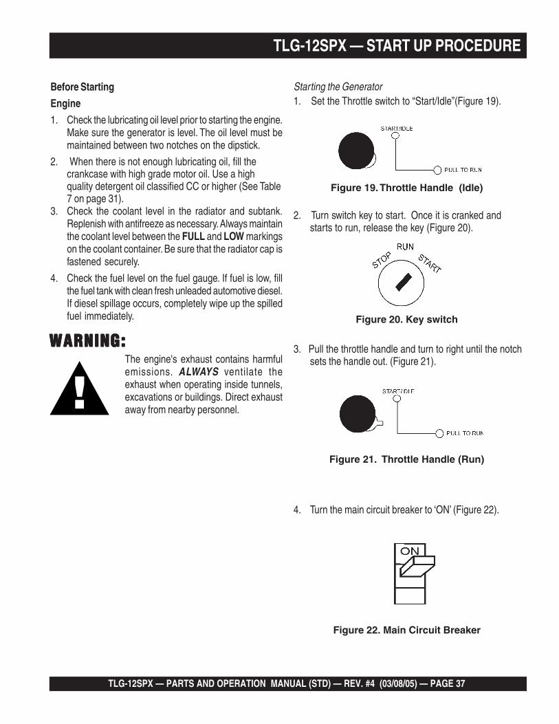
Before Starting
Generator and Control Panel
1. Be sure to disconnect the electrical load and switchthe circuit breaker to the “OFF” position prior tostarting the engine.
TLG-12SPX — PARTS AND OPERATION MANUAL (STD) — REV. #4 (03/08/05) — PAGE 37
2. Turn switch key to start. Once it is cranked andstarts to run, release the key (Figure 20).
3. Pull the throttle handle and turn to right until the notchsets the handle out. (Figure 21).
1. Set the Throttle switch to “Start/Idle”(Figure 19).Starting the Generator
4. Turn the main circuit breaker to ‘ON’ (Figure 22).
Figure 19. Throttle Handle (Idle)
Figure 20. Key switch
Figure 21. Throttle Handle (Run)
Figure 22. Main Circuit Breaker
TLG-12SPX — START UP PROCEDURE
Before Starting
Engine
1. Check the lubricating oil level prior to starting the engine.Make sure the generator is level. The oil level must bemaintained between two notches on the dipstick.
2. When there is not enough lubricating oil, fill thecrankcase with high grade motor oil. Use a highquality detergent oil classified CC or higher (See Table7 on page 31).
3. Check the coolant level in the radiator and subtank.Replenish with antifreeze as necessary. Always maintainthe coolant level between the FULL and LOW markingson the coolant container. Be sure that the radiator cap isfastened securely.
4. Check the fuel level on the fuel gauge. If fuel is low, fillthe fuel tank with clean fresh unleaded automotive diesel.If diesel spillage occurs, completely wipe up the spilledfuel immediately.
The engine's exhaust contains harmfulemissions. ALWAYS ventilate theexhaust when operating inside tunnels,excavations or buildings. Direct exhaustaway from nearby personnel.
WARNING:WARNING:WARNING:WARNING:WARNING:

PAGE 38 — TLG-12SPX — PARTS AND OPERATION MANUAL (STD) — REV. #4 (03/08/05)
A
0
40
60
75
20
Figure 26. Ammeter (No Load)
Figure 25. Voltage Adjust Control Knob
7. The ammeter (Figure 26) will indicate zero amps with noload applied. When a load is applied, this meter willindicate the amount of current that the load is drawingfrom the generator’s alternator.
5. The generator's frequency meter (Figure 23) displaysthe 60 cycle output frequency in HERTZ.
Figure 24. Voltage Meter (Volts)
6. The generator's voltage meter (Figure 24) displays the120 VAC in VOLTS. If the voltage is not within thespecified frequency tolerance, use the voltageadjustment control knob (Figure 25) to increase ordecrease the desired voltage.
Figure 23. Frequency Meter (Hz)
TLG-12SPX — SHUTDOWN PROCEDURE
ENGINE SHUTDOWNTo shutdown the generator, use the following procedure:
8. Set the circuit breaker to “ON”. Observe the generator'sammeter (Figure 27) and verify it reads the anticipatedamount of current with respect to the load. The ammeterwill only display a current reading if the load is in use.
9. The generator will run until manually stopped or anabnormal condition occurs.
Figure 27. Ammeter (Load)
A
0
40
60
75
20
1. Turn off all equipment attached to generator. Switchthe Circuit Breaker to ‘OFF’ .
2. Turn the throttle handle to the left and push in.
3. Let the engine cool by running it for 3-5 minutes with noload applied.
4. Turn the key to ‘STOP’ position and remove the key.

TLG-12SPX — PARTS AND OPERATION MANUAL (STD) — REV. #4 (03/08/05) — PAGE 39
NOTE PAGE

PAGE 40 — TLG-12SPX — PARTS AND OPERATION MANUAL (STD) — REV. #4 (03/08/05)
TLG-12SPX — MAINTENANCE
Cleaning the Fuel Strainer
Clean the fuel strainer if it contains dust or water. Removedust or water in the strainer cap and wash it in diesel. Securelyfasten the fuel strainer cap so that fuel will not leak. Checkthe fuel strainer every 200 hours of operation or once a month.
Check Oil Level
Check the crankcase oil level prior to each use, or when thefuel tank is filled. Insufficient oil may cause severe damageto the engine. Make sure the generator is level. The oil levelmust be between the two notches on the dipstick as shownon page 31, Figure 9.
Generator Storage
For storage of the generator for over 30 days, the followingis required:
Drain the fuel tank completely.
Completely drain the oil from the crankcase and refillwith fresh oil.
Clean all external parts of the generator with a cloth.
Cover the generating set and store in a clean, dry place.
General Inspection
Prior to each use, the generating set should be cleaned andinspected for deficiencies. Check for loose, missing ordamaged nuts, bolts or other fasteners. Also check for fuelor oil leaks.
Engine Side, Fuel, Oil and Coolant (Refer to the EngineInstruction Manual)
Air Cleaner
Every 50 hours: Remove air cleaner element and clean heavyduty paper element with kerosene, or foam element withliquid detergent and hot water. Wrap foam element in a clothand squeeze dry. For heavy duty paper element, wipeexcess kerosene with towel
Fuel Addition
Add diesel fuel (the grade may vary according to seasonand locations). Always pour through the mesh filter.
Removing Water from the Tank
After prolonged use, water and other impurities accumulatein the bottom of the tank. Occasionally remove the draincock and drain the contents. During cold weather, the greaterthe empty volume inside the tank, the easier it is for waterto condense. This can be reduced by always keeping thetank as full as possible.
Air Removal
If air enters the fuel injection system of a diesel engine,starting becomes impossible. After running out of fuel, orafter disassembling the fuel system, bleed the systemaccording to the following procedure.
To restart after running out of fuel, turn the key switch to the“START” position for 15-30 seconds. Try again, if needed.This unit is equipped with an automatic air bleeding system.
Service Daily
If engine is operating in very dusty and dry grass conditions,a clogged air cleaner will result in high fuel consumption,loss of power and excessive carbon buildup in thecombustion chamber.

TLG-12SPX — PARTS AND OPERATION MANUAL (STD) — REV. #4 (03/08/05) — PAGE 41
TLG-12SPX — MAINTENANCE
ECNANETNIAM/NOITCEPSNI YLIADsrH01 srH052 srH005 srH0001
ENIGNE
sleveLdiulFenignEkcehC X
renaelCriAkcehC X
leveLdicAyrettaBkcehC X
noitidnoCtleBnaFkcehC X
skaeLrofkcehC X
straPfogninesooLrofkcehC X
rotarapeSretaWkcehC X
*retliFdnaliOenignEecalpeR 1 X
retliFriAnaelC X
knaTleuFfomottoBniarD X
edistuOdnaedisnI,tinUnaelC X
*retliFleuFegnahC 2 X
leveLnoitcetorPtnalooCkcehCdnarotaidaRnaelC X
tnemelEretliFriAecalpeR X
spmalCdnasesoHllakcehC X
knaTleuFfoedisnInaelC X
ROTARENEG smhoM3revOecnatsiseRnoitalusnIerusaeM X
*1 .ylnoemittsrif,sruoh001taretliffnalioenigneecalpeR
*2 .ylnoemittsrif,sruoH052taretlifleufecalpeR

PAGE 42 — TLG-12SPX — PARTS AND OPERATION MANUAL (STD) — REV. #4 (03/08/05)
TLG-12SPX — ENGINE WIRING DIAGRAM

TLG-12SPX — PARTS AND OPERATION MANUAL (STD) — REV. #4 (03/08/05) — PAGE 43
TLG-12SPX — GENERATOR WIRING DIAGRAM

PAGE 44 — TLG-12SPX — PARTS AND OPERATION MANUAL (STD) — REV. #4 (03/08/05)
TLG-12SPX — TROUBLESHOOTING (ENGINE)
Practically all breakdowns can be prevented by properhandling and maintenance inspections, but in the event of abreakdown, use the tables shown for
diagnosis based on the Engine Troubleshooting (Table 11). Ifthe problem cannot be remedied, consult our company'sbusiness office or service plant.
GNITOOHSELBUORTENIGNE.11ELBAT
MOTPMYS MELBORPELBISSOP NOITULOS
.tratstonseodenignE
?leufoN .leufhsinelpeR
?metsysleufehtniriA .metsysdeelB
?metsysleufehtniretaW .knatleufmorfretawevomeR
?deggolcepipleuF .epipleufnaelC
?deggolcretlifleuF .retlifleufegnahcronaelC
leuffoytisocsivhgihylevissecxE?erutarepmetwoltalioenignero .lioenigneroleufdeificepsehtesU
?rebmunenatecwolhtiwleuF .leufdeificepsehtesU
noitcejniesooloteudkaelleuF?tungniniaterepip .tunnethgiT
?gnimitnoitcejnitcerrocnI .tsujdA
?nrowtfahsmacleuF .ecalpeR
?deggolcelzzonnoitcejnI .elzzonnoitcejninaelC
?gninoitcnuflampmupnoitcejnI .ecalperroriapeR
,tfahsmac,tfahsknarcfoeruzieS?gniraebrorenilrednilyc,notsip .ecalperroriapeR
?rednilycmorfkaelnoisserpmoC dnagulpwolg,tlobdaehrednilycnethgit,teksagdaehecalpeR.redlohelzzon
?gnimitevlavreporpmI .raeggnimitecalperrotcerroC
?nrowrenildnagnirnotsiP .ecalpeR
?ecnaraelcevlavevissecxE .tsujdA
.nurtonseodretratS?gninoitcnuflamretratS .ecalperroriapeR
?detcennocsidgniriW .gniriwtcennoC

TLG-12SPX — PARTS AND OPERATION MANUAL (STD) — REV. #4 (03/08/05) — PAGE 45
TLG-12SPX — TROUBLESHOOTING (ENGINE)
)DEUNITNOC(GNITOOHSELBUORTENIGNE.11ELBAT
MOTPMYS MELBORPELBISSOP NOITULOS
.htoomstonsinoituloverenignE
?ytridrodeggolcretlifleuF .egnahcronaelC
?deggolcrenaelcriA .egnahcronaelC
noitcejniesooloteudkaelleuF?tungniniaterepip .tunnethgiT
?gninoitcnuflampmupnoitcejnI .ecalperroriapeR
gninepoelzzontcerrocnI?erusserp .tsujdA
rokcutselzzonnoitcejnI?deggolc .ecalperroriapeR
?deggolcepipwolfrevoleuF .naelC
?gninoitcnuflamronrevoG .riapeR
sagtsuahxeeulbroetihwrehtiE.devresbosi
?lioenigneevissecxE .leveldeificepsehtotecudeR
ronrowrenildnagnirnotsiP?kcuts .ecalperroriapeR
?gnimitnoitcejnitcerrocnI .tsujdA
?noisserpmoctneicifeD .ecnaraelcpottsujdA
tsuahxeyargkradrokcalbrehtiE.devresbosisag
?daolrevO .daolehtnesseL
?desuleufedargwoL .leufdeificepsehtesU
?deggolcretlifleuF .egnahcronaelC
?deggolcrenaelcriA .egnahcronaelC
?noitcejnielzzontneicifeD .elzzonehtecalperroriapeR
.tuptuotneicifeD
?gnimitnoitcejnitcerrocnI .tsujdA
otmeesstrapgnivoms'enignE?gnizieseb .ecalperroriapeR
?noitcejnileufnevenU .pmupnoitcejniehtecalperroriapeR
?noitcejnielzzontneicifeD .elzzonehtecalperroriapeR
?kaelnoisserpmoC dnagulpwolg,tlobdaehrednilycnethgit,teksagdaehecalpeR.redlohelzzon

PAGE 46 — TLG-12SPX — PARTS AND OPERATION MANUAL (STD) — REV. #4 (03/08/05)
GNITOOHSELBUORTROTARENEG.71ELBAT
MOTPMYS MELBORPELBISSOP NOITULOS
tuptuOegatloVoN
?evitcefedretemtloVCA .retemtlovagnisuegatlovtuptuokcehC
?esoolnoitcennocgniriwsI .riaperdnagniriwkcehC
?evitcefedRVAsI .yrassecenfiecalpeR
?reifitceRgnitatoRevitcefeD .ecalperdnakcehC
tuptuOegatloVwoL
?tcerrocdeepsenignesI ."hgiH"otrevelelttorhtenignenruT
?esoolsnoitcennocgniriwsI .riaperdnagniriwkcehC
?RVAevitcefeD .yrassecenfiecalpeR
tuptuOegatloVhgiH?esoolsnoitcennocgniriwsI .riaperdnagniriwkcehC
?RVAevitcefeD .yrassecenfiecalpeR
deppirTrekaerBtiucriC
?daolnitiucriCtrohS .riaperdnadaolkcehC
?tnerrucrevO .ecuderdnastnemeriuqerdaolmrifnoC
?rekaerbtiucricevitcefeD .ecalperdnakcehC
?detautcayaleRtnerrucrevO .ecalperdnatnemeriuqerdaolmrifnoC
Practically all breakdowns can be prevented by proper handling and maintenance inspections, but in the event of abreakdown, use the tables shown for diagnosis based on the Engine and Generator Troubleshooting (Table 12). If theproblem cannot be remedied, consult our company's business office or service plant.
TLG-12SPX — TROUBLESHOOTING (GENERATOR)

TLG-12SPX — PARTS AND OPERATION MANUAL (STD) — REV. #4 (03/08/05) — PAGE 47
NOTE PAGE

PAGE 48 — TLG-12SPX — PARTS AND OPERATION MANUAL (STD) — REV. #4 (03/08/05)
How to read the marks and remarks used in this partsbook.
Items Found In the “Remarks” Column
Serial Numbers-Where indicated, this indicates a serialnumber range (inclusive) where a particular part is used.
Model Number-Where indicated, this shows that thecorresponding part is utilized only with this specific modelnumber or model number variant.
Items Found In the “Items Number” Column
All parts with same symbol in the number column, *, #,+, or %, belong to the same assembly or kit.
Note: If more than one of the same reference number islisted, the last one listed indicates newest (or latest)part available.
EXPLANATION OF CODE IN REMARKS COLUMN

TLG-12SPX — PARTS AND OPERATION MANUAL (STD) — REV. #4 (03/08/05) — PAGE 49
TLG-12SPX W/ISUZU 3LB1 DIESELENGINE 1 TO 3 UNITS
TLG-12SPX — SUGGESTED SPARE PARTS
NOTEPart number on this Suggested SpareParts list may supercede/replace theP/N shown in the text pages of this
book.
Qty. P/N Description1 ......... 0601806537 ..... CIRCUIT BREAKER1 ......... 0601820663 ..... AUTOMATIC VOLTAGE REGULATOR1 ......... 0601840073 ..... RHEOSTAT VOLTAGE REGULATOR1 ......... 0601840121 ..... KNOB RHEOSTAT1 ......... 8522015503 ..... RADIATOR HOSE (UPPER)1 ......... 8971076820 ..... RADIATOR HOSE (LOWER)5 ......... 8944567411 ..... OIL FILTER5 ......... 8970488490 ..... FUEL FILTER5 ......... 0602046202 ..... AIR ELEMENT1 ......... 1824100990 ..... UNIT OIL PRESSURE1 ......... 8941268220 ..... UNIT WATER PRESSURE1 ......... 0208006120 ..... FAN BELT

PAGE 50 — TLG-12SPX — PARTS AND OPERATION MANUAL (STD) — REV. #4 (03/08/05)
TLG-12SPX --- GENERATOR ASSY.GENERATOR ASSY.

TLG-12SPX — PARTS AND OPERATION MANUAL (STD) — REV. #4 (03/08/05) — PAGE 51
NO. PART NO. ITEM QTY. REMARKS
TLG-12SPX --- GENERATOR ASSY.
GENERATOR ASSY.
1 B0110000403 ROTOR ASSY. 11-1 0601820037 RECTIFIER ...................................... 1 ......... S10VB601-2 0601822638 SURGE ABSORBER ....................... 1 ......... TNR15G 431K1-3 0071206307 BEARING ......................................... 1 ......... 6307DDU1-4 0080000035 SNAP RING 12 1711027003 FAN 13 7611611003 COUPLING DISK 14 3311612004 WASHER, COUPLING HUB 15 0012808025 HEX. HEAD BOLT ............................ 6 ......... REPLACES 00128080256 0012308030 HEX. HEAD BOLT 67 D4153100102 END BRACKET 18 8521384003 ARMATURE ASSY. 19 D4153000202 END BRACKET 110 B0137000003 FIELD ASSY. EXCITER 111 0017105035 HEX. HEAD BOLT 412 D4153400403 GROMMET 213 D4131200004 SET BOLT 414 0040012000 LOCK WASHER 415 031112230 PLAIN WASHER .............................. 4 ......... REPLACES 004121200016 0030012000 HEX. HEAD BOLT 417 B0131300104 COVER 118 0017108030 HEX. HEAD BOLT 419 012010030 HEX. HEAD BOLT ............................ 6 ......... REPLACES 001031003020 030210250 LOCK WASHER ............................... 6 ......... REPLACES 004251000021 031112230 PLAIN WASHER .............................. 6 ......... REPLACES 004121000022 0207210000 HEX. NUT 223 D5131300003 COVER 124 0017105025 HEX. HEAD BOLT 125 8521320104 GENERATOR FOOT 126 8521320004 GENERATOR FOOT 127 0017110025 HEX. HEAD BOLT 828 7605419004A RUBBER SUSPENSION .................. 2 ......... REPLACES 760541900429 0207010000 HEX. NUT 230 0070506803 BEARING ......................................... 1 ......... 6803ZZ

PAGE 52 — TLG-12SPX — PARTS AND OPERATION MANUAL (STD) — REV. #4 (03/08/05)
TLG-12SPX --- CONTROL PANEL ASSY.
CONTROL PANEL ASSY.

TLG-12SPX — PARTS AND OPERATION MANUAL (STD) — REV. #4 (03/08/05) — PAGE 53
NO. PART NO. ITEM QTY. REMARKS
TLG-12SPX --- CONTROL PANEL ASSY.
CONTROL PANEL ASSY.
1 8521827203 CONTROL PANEL 12 0605010060 HINGE ........................................................ 2 ......... B1075L3 0027103010 MACHINE SCREW .................................... 8 ......... REPLACES 00211030104 0021806030 MACHINE SCREW 25 0601800408 FREQUENCY METER ............................... 1 ......... FCF5 220V 45~65Hz6 0601805745 AC AMMETER ........................................... 1 ......... ACF50~75A7 0601800281 AC VOLTMETER ........................................ 1 ......... SCF5A 0~150V 0~300V8 0601840073 RHEOSTAT (VOLTAGE REGULATOR) ....... 1 ......... RA20A2SE102BJ 2W 1K OHM9 0601840121 KNOB 110 0601806537 CIRCUIT BREAKER .................................. 1 ......... SC50NS 50A11 0021004060 MACHINE SCREW 2
0040004000 LOCK WASHER 2031104080 PLAIN WASHER ........................................ 2 ......... REPLACES 0041204000
12 8970444180 STARTER SWITCH .................................... 1 ......... REPLACES 06021000098944024980 STARTER KEY .......................................... 2 ......... REPLACES 0602100200
13 0601810523 INDICATOR ASSY. ..................................... 1 ......... PLB128Q0601810207 BULB 4
14 0601800680 HOUR METER ........................................... 1 ......... 1511315 0027103512 MACHINE SCREW 2
0030003500 HEX. NUT 20040403500 WASHER 2
16 7672142003 SLIDE LEVER 117 0601840190 KNOB ......................................................... 1 ......... REPLACES 080501290418 8522144103 THROTTLE CABLE 119 3032143004 SPRING 120 8522141004 BRACKET 121 011006010 HEX. HEAD BOLT ...................................... 3 ......... REPLACES 001710601022 0601812597 RECEPTACLE ............................................ 1 ......... 520R 125V 20A23 0601811031 RECEPTACLE ............................................ 1 ......... L530R 125V 30A24 0601811033 RECEPTACLE ............................................ 1 ......... L630R 250V 30A25 0601811034 RECEPTACLE ............................................ 1 ......... CA6369125/250V 50A
REPLACES 0601812565

PAGE 54 — TLG-12SPX — PARTS AND OPERATION MANUAL (STD) — REV. #4 (03/08/05)
TLG-12SPX --- CONTROL PANEL ASSY.
CONTROL PANEL ASSY.
TLG-12SPX — PARTS AND OPERATION MANUAL (STD) — REV. #4 (03/08/05) — PAGE 55
NO. PART NO. ITEM QTY. REMARKS
TLG-12SPX --- CONTROL PANEL ASSY.
CONTROL PANEL ASSY.
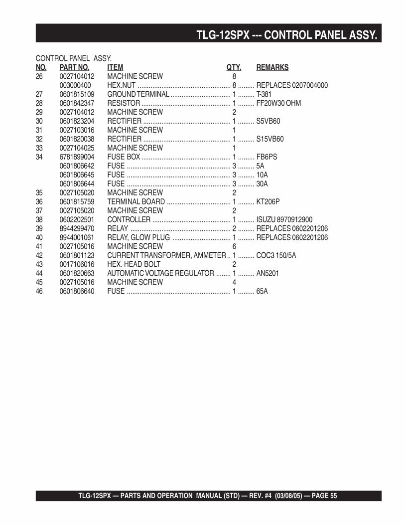
26 0027104012 MACHINE SCREW 8003000400 HEX.NUT ................................................... 8 ......... REPLACES 0207004000
27 0601815109 GROUND TERMINAL ................................. 1 ......... T-38128 0601842347 RESISTOR ................................................. 1 ......... FF20W30 OHM29 0027104012 MACHINE SCREW 230 0601823204 RECTIFIER ................................................ 1 ......... S5VB6031 0027103016 MACHINE SCREW 132 0601820038 RECTIFIER ................................................ 1 ......... S15VB6033 0027104025 MACHINE SCREW 134 6781899004 FUSE BOX ................................................. 1 ......... FB6PS
0601806642 FUSE ......................................................... 3 ......... 5A0601806645 FUSE ......................................................... 3 ......... 10A0601806644 FUSE ......................................................... 3 ......... 30A
35 0027105020 MACHINE SCREW 236 0601815759 TERMINAL BOARD ................................... 1 ......... KT206P37 0027105020 MACHINE SCREW 238 0602202501 CONTROLLER ........................................... 1 ......... ISUZU 897091290039 8944299470 RELAY ....................................................... 2 ......... REPLACES 060220120640 8944001061 RELAY, GLOW PLUG ................................ 1 ......... REPLACES 060220120641 0027105016 MACHINE SCREW 642 0601801123 CURRENT TRANSFORMER, AMMETER .. 1 ......... COC3 150/5A43 0017106016 HEX. HEAD BOLT 244 0601820663 AUTOMATIC VOLTAGE REGULATOR ........ 1 ......... AN520145 0027105016 MACHINE SCREW 446 0601806640 FUSE ......................................................... 1 ......... 65A

PAGE 56 — TLG-12SPX — PARTS AND OPERATION MANUAL (STD) — REV. #4 (03/08/05)
TLG-12SPX ENGINE AND RADIATOR ASSY.
ENGINE AND RADIATOR ASSY.

TLG-12SPX — PARTS AND OPERATION MANUAL (STD) — REV. #4 (03/08/05) — PAGE 57
TLG-12SPX ENGINE AND RADIATOR ASSY.
NO. PART NO. ITEM QTY. REMARKSENGINE AND RADIATOR ASSY.
1 8520150004 ENGINE ........................................... 1 ......... ISUZU 3LB11-1 8943142633 CARTRIDGE, OIL FILTER ............... 1 ......... REPLACES 0602041210
060201140 FAN BELT ........................................ 1 ......... ISUZU 89706879802 8525112104 ENGINE FOOT 23 0012810020 HEX. HEAD BOLT 84 7605419004A RUBBER SUSPENSION .................. 2 ......... REPLACES 76054190045 0207010000 HEX. NUT 26 0602011956 RADIATOR ....................................... 1 ......... OB890100006-1 06020110888 CAP, RADIATOR .............................. 1 ......... R9120107007 8702014004 RUBBER MOUNT 28 605000460 RUBBER MOUNT ............................ 2 ......... 66592103819 8522015503 RADIATOR HOSE 110 8522015602 RADIATOR HOSE 111 0605515112 HOSE BAND .................................... 2 ......... ∅3812 0605515114 HOSE BAND .................................... 1 ......... ∅4213 5142150140 AIR FILTER, ELEMENT ................... 1 ......... REPLACES 894152113013-1 0602040690 INDICATOR, DUST 114 8970497220 BAND, AIR CLEANER ..................... 2 ......... REPLACES 060204050115 8522031004 BRACKET, AIR CLEANER 116 011008020 HEX. HEAD BOLT ............................ 6 ......... REPLACES 001710802017 8522032003 HOSE AIR CLEANER 118 6602032103 HOSE AIR CLEANER 119 0605515020 HOSE BAND .................................... 1 ......... ∅5520 0605515001 HOSE BAND .................................... 2 ......... ∅6021 1622014103 DRAIN JOINT, WATER 122 1502025103C DRAIN JOINT, OIL ........................... 1 ......... REPLACES 150202510323 0802011104 PLUG 224 015000018 O RING ............................................ 2 ......... AP1825 0017106016 HEX. HEAD BOLT 426 0199900900 DRAIN HOSE 127 0199900450 DRAIN HOSE 128 0605515094 HOSE BAND .................................... 4 ......... ∅1229 0805010004 DRAIN JOINT 130 3362054104 JOINT BOLT 131 0602021190 PACKING ......................................... 2 ......... SW2232 0192200435 DRAIN HOSE 133 0605515003 HOSE BAND .................................... 2 ......... ∅2734 0802081403 RESERVE TANK 135 0802081104 CAP, RESERVE TANK 136 8702082004 BRACKET, RESERVE TANK 137 011606025 HEX. HEAD BOLT ............................ 1 ......... REPLACES 001710602538 0017106016 HEX. HEAD BOLT 239 0199900320 HOSE 140 7222016304 HOSE 141 060551594 HOSE BAND .................................... 3 ......... ∅1242 060551526 HOSE BAND .................................... 1 ......... ∅44

PAGE 58 — TLG-12SPX — PARTS AND OPERATION MANUAL (STD) — REV. #4 (03/08/05)
TLG-12SPX --- BATTERY ASSY.
BATTERY ASSY.

TLG-12SPX — PARTS AND OPERATION MANUAL (STD) — REV. #4 (03/08/05) — PAGE 59
NO. PART NO. ITEM QTY. REMARKS
TLG-12SPX --- BATTERY ASSY.
BATTERY ASSY.
1 0167306531 BATTERY ......................................... 1 ......... 65D31R2 7612251004 BATTERY SHEET 13 8522250004 BATTERY BAND 14 7612252004 BATTERY BOLT 25 0037808000 WING NUT 26 0040008000 LOCK WASHER 27 031108160 PLAIN WASHER .............................. 2 ......... REPLACES 0041208000
BATTERY CABLE 1BATTERY CABLE 1
10 0602220310 TERMINAL ASSY. ........................... 1 ......... NO.9P11 0602220311 TERMINAL ASSY. ........................... 1 ......... NO 9N12 0602220600 TERMINAL CAP .............................. 1 ......... TC7R

PAGE 60 — TLG-12SPX — PARTS AND OPERATION MANUAL (STD) — REV. #4 (03/08/05)
TLG-12SPX --- MUFFLER ASSY.
MUFFLER ASSY.

TLG-12SPX — PARTS AND OPERATION MANUAL (STD) — REV. #4 (03/08/05) — PAGE 61
NO. PART NO. ITEM QTY. REMARKS
TLG-12SPX --- MUFFLER ASSY.
MUFFLER ASSY.
1 8522310102 MUFFLER 12 011008020 HEX. HEAD BOLT ............................ 4 ......... REPLACES 00171080203 8522330003 EXHAUST PIPE 14 8522332004 EXHAUST PIPE 15 8522331004 EXHAUST PIPE 16 011008020 HEX. HEAD BOLT ............................ 2 ......... REPLACES 00171080207 0017106016 HEX. HEAD BOLT 18 3312320004 PIPE BAND 29 011208035 HEX. HEAD BOLT ............................ 2 ......... REPLACES 001710803510 897042080 GASKET .......................................... 1 ......... REPLACES 060232011011 1502336004 GASKET 112 020108060 HEX. NUT ........................................ 4 ......... REPLACES 020720800013 011208035 HEX. HEAD BOLT ............................ 2 ......... REPLACES 0017108035

PAGE 62 — TLG-12SPX — PARTS AND OPERATION MANUAL (STD) — REV. #4 (03/08/05)
TLG-12SPX --- FUEL TANK ASSY.
FUEL TANK ASSY.

TLG-12SPX — PARTS AND OPERATION MANUAL (STD) — REV. #4 (03/08/05) — PAGE 63
NO. PART NO. ITEM QTY. REMARKS
TLG-12SPX --- FUEL TANK ASSY.
FUEL TANK ASSY.
1 8525500003 FUEL TANK 11-1 0810105900 CAP, FUEL TANK ............................. 1 ......... REPLACES 08101058001-2 0810105900 FUEL FILTER 11-3 0267700200 HOSE, FUEL GAUGE 11-4 0605515005 HOSE BAND 22 8525525003 BRACKET, FUEL TANK 13 011008020 HEX. HEAD BOLT ............................ 4 ......... REPLACES 00171080204 8525523004 TANK BAND 25 0805003404 PAD, TANK BAND 46 011008020 HEX. HEAD BOLT ............................ 2 ......... REPLACES 00171080207 020108060 HEX.NUT ......................................... 4 ......... REPLACES 02070080008 1555527004 TANK SHEET 29 7812014003 DRAIN JOINT 110 0802011104 PLUG 111 0150000018 O RING ............................................ 1 ......... AP`1812 0017106016 HEX. HEAD BOLT 213 0199900830 DRAIN HOSE 114 0605515094 HOSE BAND .................................... 2 ......... ∅1215 8525546014 BRACKET 116 011208025 HEX. HEAD BOLT ............................ 2 ......... REPLACES 001710802517 8971041891 FUEL FILTER ................................... 1 ......... REPLACES 1552143160
8970713480 ELEMENT, FUEL FILTER 118 0017108065 HEX. HEAD BOLT 119 0602023175 FUEL PUMP .................................... 1 ......... REPLACES 060202317520 0199900350 SUCTION HOSE 121 0199900300 SUCTION HOSE 122 0199900400 SUCTION HOSE 123 0199700500 RETURN HOSE 124 0199700270 RETURN HOSE 125 0605515094 HOSE BAND .................................... 6 ......... ∅1226 0605515096 HOSE BAND .................................... 4 ......... ∅827 1615511204 RUBBER SEAL 1

PAGE 64 — TLG-12SPX — PARTS AND OPERATION MANUAL (STD) — REV. #4 (03/08/05)
ENCLOSURE ASSY.
TLG-12SPX --- ENCLOSURE ASSY.

TLG-12SPX — PARTS AND OPERATION MANUAL (STD) — REV. #4 (03/08/05) — PAGE 65
NO. PART NO. ITEM QTY. REMARKSENCLOSURE ASSY.
TLG-12SPX --- ENCLOSURE ASSY.
1 8525110012 BASE 18525910003 ACOUSTIC SHEET 1
2 8525110604 FLOOR PANEL 13 0017106016 HEX. HEAD BOLT 84 8525118003 PANEL 1
8525911004 ACOUSTIC SHEET 15 0017106016 HEX. HEAD BOLT 86 8525114003 DUCT 1
8525912004 ACOUSTIC SHEET 17 8525115003 BATTERY FRAME 1
8525913004 ACOUSTIC SHEET 18 0017106016 HEX. HEAD BOLT 89 8525181103 SPLASHER PANEL 1
8525980004 ACOUSTIC SHEET 110 8525181203 SPLASHER PANEL 1
8525980004 ACOUSTIC SHEET 111 0017106016 HEX. HEAD BOLT 1212 8525120003 FRONT FRAME 1
8525920003 ACOUSTIC SHEET 113 0601850239 GROMMET ...................................... 2 ......... B14214 0601850253 GROMMET ...................................... 2 ......... B36215 8525125003 DUCT COVER 1
8525922003 ACOUSTIC SHEET 116 0017106016 HEX. HEAD BOLT 517 011008020 HEX. HEAD BOLT ............................ 2 ......... REPLACES 001710802018 8525121102 FRONT FRAME 1
8525921004 ACOUSTIC SHEET 119 011008020 HEX. HEAD BOLT ............................ 9 ......... REPLACES 001710802020 8522030003 FAN GUARD 121 0017106016 HEX. HEAD BOLT 422 8525132113 HANGER .......................................... 1 ......... S/N5107198 TO 5107225
8525132223 HANGER .......................................... 1 ......... S/N5107226~23 8525132013 HANGER .......................................... 1 ......... S/N5107198 TO 5107225
8525132023 HANGER .......................................... 1 ......... S/N5107226~24 0012312030 HEX. HEAD BOLT 6
THE PART NUMBER DEFAULT IS SCARLET COLOR.INDICATE THE LETTERS BELOW TO INDICATEDIFFERENT COLOR OF UNIT:
MQW-WHITE
THE SERIAL NUMBER MAY BE REQUIRED.

PAGE 66 — TLG-12SPX — PARTS AND OPERATION MANUAL (STD) — REV. #4 (03/08/05)
ENCLOSURE ASSY.
TLG-12SPX --- ENCLOSURE ASSY.
THE PART NUMBER DEFAULT IS SCARLET COLOR.INDICATE THE LETTERS BELOW TO INDICATEDIFFERENT COLOR OF UNIT:
MQW-WHITE
THE SERIAL NUMBER MAY BE REQUIRED.
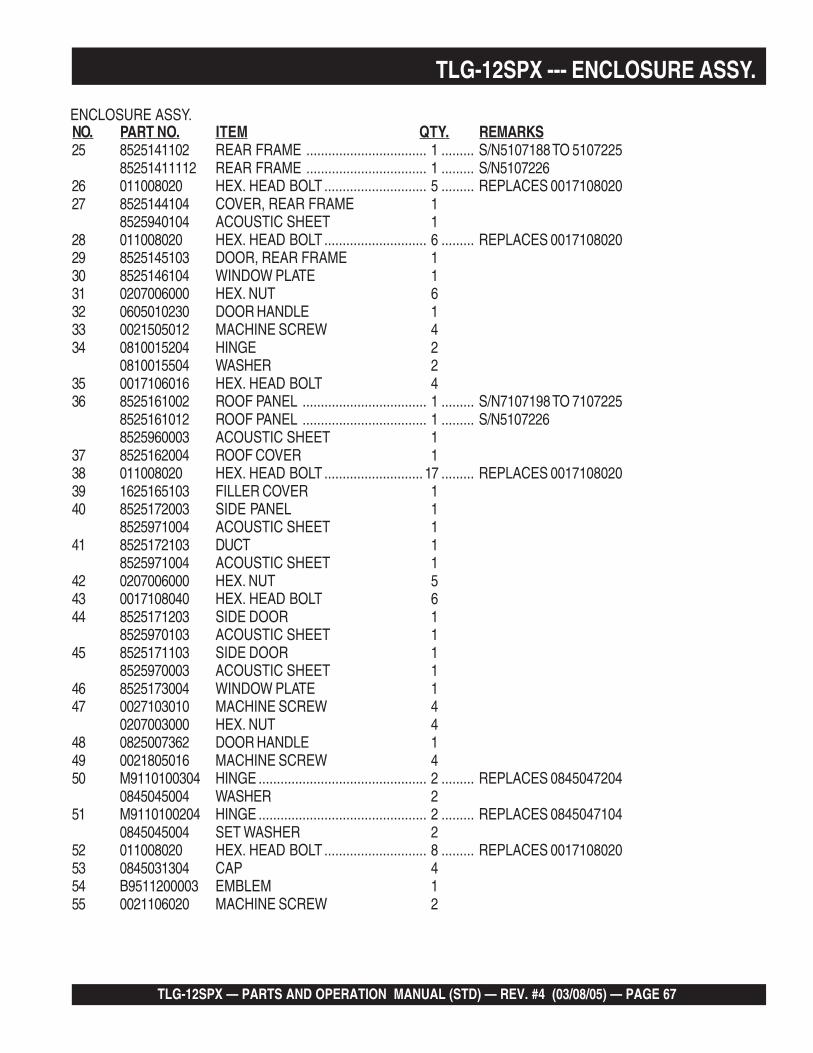
TLG-12SPX — PARTS AND OPERATION MANUAL (STD) — REV. #4 (03/08/05) — PAGE 67
25 8525141102 REAR FRAME ................................. 1 ......... S/N5107188 TO 510722585251411112 REAR FRAME ................................. 1 ......... S/N5107226
26 011008020 HEX. HEAD BOLT ............................ 5 ......... REPLACES 001710802027 8525144104 COVER, REAR FRAME 1
8525940104 ACOUSTIC SHEET 128 011008020 HEX. HEAD BOLT ............................ 6 ......... REPLACES 001710802029 8525145103 DOOR, REAR FRAME 130 8525146104 WINDOW PLATE 131 0207006000 HEX. NUT 632 0605010230 DOOR HANDLE 133 0021505012 MACHINE SCREW 434 0810015204 HINGE 2
0810015504 WASHER 235 0017106016 HEX. HEAD BOLT 436 8525161002 ROOF PANEL .................................. 1 ......... S/N7107198 TO 7107225
8525161012 ROOF PANEL .................................. 1 ......... S/N51072268525960003 ACOUSTIC SHEET 1
37 8525162004 ROOF COVER 138 011008020 HEX. HEAD BOLT ........................... 17 ......... REPLACES 001710802039 1625165103 FILLER COVER 140 8525172003 SIDE PANEL 1
8525971004 ACOUSTIC SHEET 141 8525172103 DUCT 1
8525971004 ACOUSTIC SHEET 142 0207006000 HEX. NUT 543 0017108040 HEX. HEAD BOLT 644 8525171203 SIDE DOOR 1
8525970103 ACOUSTIC SHEET 145 8525171103 SIDE DOOR 1
8525970003 ACOUSTIC SHEET 146 8525173004 WINDOW PLATE 147 0027103010 MACHINE SCREW 4
0207003000 HEX. NUT 448 0825007362 DOOR HANDLE 149 0021805016 MACHINE SCREW 450 M9110100304 HINGE .............................................. 2 ......... REPLACES 0845047204
0845045004 WASHER 251 M9110100204 HINGE .............................................. 2 ......... REPLACES 0845047104
0845045004 SET WASHER 252 011008020 HEX. HEAD BOLT ............................ 8 ......... REPLACES 001710802053 0845031304 CAP 454 B9511200003 EMBLEM 155 0021106020 MACHINE SCREW 2
ENCLOSURE ASSY.
TLG-12SPX --- ENCLOSURE ASSY.
NO. PART NO. ITEM QTY. REMARKS

PAGE 68 — TLG-12SPX — PARTS AND OPERATION MANUAL (STD) — REV. #4 (03/08/05)
TLG-12SPX --- RUBBER SEAL ASSY.
RUBBER SEAL ASSY.

TLG-12SPX — PARTS AND OPERATION MANUAL (STD) — REV. #4 (03/08/05) — PAGE 69
NO. PART NO. ITEM QTY. REMARKS
TLG-12SPX --- RUBBER SEAL ASSY.
RUBBER SEAL ASSY.
56 0227600590 RUBBER SEAL 257 0227600835 RUBBER SEAL 258 0229400560 RUBBER SEAL 259 0229400550 RUBBER SEAL 160 0229400840 RUBBER SEAL 261 0229400220 RUBBER SEAL 262 0229400590 RUBBER SEAL 163 0229200210 RUBBER SEAL 264 0229200615 RUBBER SEAL 265 0226900570 RUBBER SEAL 166 0229200680 RUBBER SEAL 1

PAGE 70 — TLG-12SPX — PARTS AND OPERATION MANUAL (STD) — REV. #4 (03/08/05)
TLG-12SPX --- DECALS
DECAL ASSY.

TLG-12SPX — PARTS AND OPERATION MANUAL (STD) — REV. #4 (03/08/05) — PAGE 71
NO. PART NO. ITEM QTY. REMARKS
TLG-12SPX --- DECALS
DECAL ASSY.
1-1 7440611013 DECAL; OPERATING PROCEDURE ................... 1 ....... S1742B2-1 7670623004 DECAL; VOLTAGE REGULATOR.......................... 1 ....... S37372-2 0840624504 DECAL; CIRCUIT BREAKER ............................... 1 ....... S-30312-3 8520621104 DECAL; STARTER SWITCH ................................ 1 ....... S47532-4 7670622004 DECAL; SPEED CONTROL HANDLE .................. 1 ....... S38222-5 8520620203 DECAL; AC POWER OUTPUT ............................ 1 ....... S47542-6 7670624004 DECAL; GROUND ................................................ 1 ....... S38212-7 8700611904 DECAL; DANGER ................................................ 1 ....... S49853-1 1630610404 DECAL; CAUTION ................................................ 1 ....... S14063-2 1320620904 DECAL; DIESEL FUEL ........................................ 1 ....... S17563-3 7810680104 DECAL; FUEL DRAIN .......................................... 1 ....... S30603-4 8520635004 DECAL; FUEL COCK ........................................... 1 ....... S50683-5 8700615204 DECAL; FUEL GAUGE 14-1 0800628504 DECAL; GROUND ................................................ 1 ....... S11234-2 1630645004 DECAL; OIL DRAIN ............................................. 1 ....... S14034-3 1630647004 DECAL; COOLANT DRAIN .................................. 1 ....... S14044-4 1630610504 DECAL; CAUTION ................................................ 1 ....... S14094-5 6360610304 DECAL; WATER ................................................... 2 ....... S18804-6 1320621504 DECAL; SUPPORT HOOK................................... 2 ....... S22574-7 6390671104 DECAL; IMPORTANT ........................................... 1 ....... S23774-8 0840625902 DECAL; MQ ......................................................... 1 ....... S30574-9 8700611514 DECAL; WARNING ............................................... 1 ....... S4926A4-10 8700611804 DECAL; WARNING ............................................... 1 ....... S49844-11 8520632003 STRIPE 14-12 8520632604 STRIPE 14-13 8520632504 STRIPE 14-14 8520632704 STRIPE 14-15 8520632104 STRIPE 14-16 8520632304 STRIPE 14-17 8520632404 STRIPE 14-18 8520632204 STRIPE 14-19 0600501103 DECAL; WARNING 14-20 0820650604 DECAL; DANGER 1

PAGE 72 — TLG-12SPX — PARTS AND OPERATION MANUAL (STD) — REV. #4 (03/08/05)
CYLINDER HEAD COVER ASSY.
ISUZU 3LB1 — CYLINDER HEAD COVER ASSY.

TLG-12SPX — PARTS AND OPERATION MANUAL (STD) — REV. #4 (03/08/05) — PAGE 73
ISUZU 3LB1 — CYLINDER HEAD COVER ASSY.
EA1013
CYLINDER HEAD COVER ASSY.
NO PART NO PART NAME QTY. REMARKS1 8970655484 CYLINDER HEAD COVER 14 8941332075 OIL FILLER CAP............................. 1 .......... INCL. ITEMS W/*5* 8941236231 OIL FILLER GASKET 128 0280806200 BOLT 969 8970655472 GASKET 1

PAGE 74 — TLG-12SPX — PARTS AND OPERATION MANUAL (STD) — REV. #4 (03/08/05)
ISUZU 3LB1 — CYLINDER HEAD ASSY.
CYLINDER HEAD ASSY.

TLG-12SPX — PARTS AND OPERATION MANUAL (STD) — REV. #4 (03/08/05) — PAGE 75
ISUZU 3LB1 — CYLINDER HEAD ASSY.
CYLINDER HEAD ASSY.
NO PART NO PART NAME QTY. REMARKS1 8971056750 CYLINDER HEAD ASSY. .................. 1 ........ OCT. 1993 TO OCT. 1996; INCL. ITEMS W/*
8971633991 CYLINDER HEAD ASSY. .................. 1 ........ NOV. 1996~2 8970439332 GASKET 13A 8944637840 BOLT 43B 8970369591 BOLT 84* 8970317490 VALVE GUIDE 65A* 8970317101 VALVE INSERT SEAT 35B* 8970317110 VALVE INSERT SEAT 37A* 1096000112 SEALING CUP 47B* 1096000051 SEALING CUP 110 8971065490 GLOW PLUG 311 8970346333 CONNECTOR 112 8970853900 HANGER 114 5093000650 EXHAUST MANIFOLD STUD 215 028088160 BOLT 125* 511190090 CYLINDER HEAD PLUG 427* 8970446351 HOT PLUG 336 8941105591 OIL SEAL 641 0280808160 BOLT 150 8970946410 ROCKER ARM STUD 5103 5096050050 PLUG 2168 8970853890 FRONT HANGER 1

PAGE 76 — TLG-12SPX — PARTS AND OPERATION MANUAL (STD) — REV. #4 (03/08/05)
ISUZU 3LB1 — CYLINDER BLOCK ASSY.
CYLINDER BLOCK ASSY.

TLG-12SPX — PARTS AND OPERATION MANUAL (STD) — REV. #4 (03/08/05) — PAGE 77
ISUZU 3LB1 — CYLINDER BLOCK ASSY.
CYLINDER BLOCK ASSY.
NO. PART NO. PART NAME QTY. REMARKS1 8971061943 CYLINDER BLOCK ASSY. ..................................... 1 .......... DEC. 1993 TO MAR. 1995;
INCL. ITEMS W/*8971290721 CYLINDER BLOCK ASSY. ..................................... 1 .......... APR. 1995 TO MAR. 19978971691440 CYLINDER BLOCK ASSY. ..................................... 1 .......... APR. 1997~
6A* 8942298530 SEALING CUP 46B* 1096000112 SEALING CUP 18* 8941674711 BOLT 815A 1096050500 OIL GALLERY PLUG, PT 1/8 115B 1096050040 OIL GALLERY PLUG, PT 1/8 SQ. HEAD 115C 1096050190 OIL GALLERY PLUG, PT 1/4 154 9041106160 OIL PAN STUD 261A 9081606160 STRAIGHT PIN 261B 9098785320 STRAIGHT PIN ...................................................... 3 .......... REPLACES 908160616083 9081608160 FLYWHEEL PIN 289* 5096000130 OIL GALLERY CUP 9114 5137210281 WATER DRAIN NIPPLE 1141 0280806140 BOLT, M6X16 FLANGE 4144 0911502060 NUT 2205 1093050050 STUD 6232 9041108400 WATER PUMP STUD 1297 8971062031 COVER 1300 9041106160 COVER STUD, M6X16 L=25 3
8943438960 COVER STUD, M6X19 L=27 1416 8943255950 OIL FILTER STUD 1439 8970470560 BEARING 1440 8970394953 PIN 2441A 9112290581 DOWEL, D=11 4441C 8942008190 DOWEL, D=15 2442 8970471421 THRUST PLUG 1443A 5096000130 SEALING CAP 1443B 1096000121 SEALING CAP 1

PAGE 78 — TLG-12SPX — PARTS AND OPERATION MANUAL (STD) — REV. #4 (03/08/05)
ISUZU 3LB1 — OIL PAN AND LEVEL GAUGE ASSY.
OIL PAN AND LEVEL GAUGE ASSY.

TLG-12SPX — PARTS AND OPERATION MANUAL (STD) — REV. #4 (03/08/05) — PAGE 79
ISUZU 3LB1 — OIL PAN AND LEVEL GAUGE ASSY.
OIL PAN AND LEVEL GAUGE ASSY.
NO. PART NO. PART NAME QTY. REMARKS1 8971322101 OIL PAN ASSY. ............................................... 1 .......... REPLACES 8970439362;
INCL .ITEMS W/*2 8970439421 OIL LEVER GAUGE 13* 1096230570 GASKET 14* 9096620120 OIL DRAIN PLUG 123 8971351410 BOLT ............................................................. 16 .......... REPLACES 028080614024 8971378360 OIL PAN NUT .................................................. 2 .......... REPLACES 0911502060

PAGE 80 — TLG-12SPX — PARTS AND OPERATION MANUAL (STD) — REV. #4 (03/08/05)
ISUZU 3LB1 — CAMSHAFT AND VALVE ASSY.
CAMSHAFT AND VALVE ASSY.

TLG-12SPX — PARTS AND OPERATION MANUAL (STD) — REV. #4 (03/08/05) — PAGE 81
ISUZU 3LB1 — CAMSHAFT AND VALVE ASSY.
CAMSHAFT AND VALVE ASSY.
NO. PART NO. PART NAME QTY. REMARKS1 8970621401 CAMSHAFT .................................................... 1 .......... INCL. ITEMS W/*4 8971021240 INLET VALVE 35 8970346283 EXHAUST VALVE 36 5094000530 NUT 134* 9098786260 PIN 153 8970668721 ROCKER ARM SHAFT 155 9992023140 PLUG 157 0280806250 BOLT, M6X25 FLANGE 4
0286806160 BOLT, M6X16 465 8942395010 SPLIT COLLAR 1268 8970346291 VALVE SPRING 671 8942510311 SPRING SEAT 678A 8970668761 ROCKER ARM, INLET .................................... 3 .......... APR. 1992 TO SEP. 1992
8972125180 ROCKER ARM, INLET .................................... 3 .......... OCT. 1992~;REPLACES 8971164480
78B 8970668781 ROCKER ARM, EXHAUST ............................. 3 .......... APR. 1992 TO SEP. 199278B 8972125200 ROCKER ARM, EXHAUST ............................. 3 .......... OCT. 1992’;
REPLACES 897116450081 8970104850 SCREW 683 9091115060 NUT 688 8970668692 PUSH ROD 689 8971243690 VALVE TAPPET .............................................. 6 .......... REPLACES 897034630191 0911502060 NUT 592A 8971056791 ROCKER ARM BRACKET .............................. 1 .......... OCT. 1993 TO MAY 1995
8971312450 ROCKER ARM BRACKET .............................. 1 .......... JUN. 1995 TO OCT. 199592B 8971634112 ROCKER ARM BRACKET 195 8970698871 ROCKER SHAFT SPRING 398 9081605160 SHAFT PIN ..................................................... 1 .......... REPLACES 9096785100107 8971297800 IDLE GEAR SHAFT ........................................ 1 .......... REPLACES 8970728290111 5125350051 COLLAR 1112 8970375940 IDLER GEAR .................................................. 1 .......... APR. 1992 TO SEP. 1995
8971297820 IDLER GEAR .................................................. 1 .......... OCT. 1995~196 9091801620 SNAP RING 1228A 9111290830 SEALING CUP 1228B 8970395260 SEALING CUP 1263 9095714140 GASKET 1270 8971022880 INJECTION PUMP GEAR 1271 0280908600 BOLT ............................................................... 2 .......... APR. 1992 TO SEPT. 1995
0280908450 BOLT ............................................................... 2 .......... OCT. 1995~272* 8970620480 CAMSHAFT RING 1273A* 9000906100 CAMSHAFT BEARING 1273B* 9000906570 CAMSHAFT BEARING 1
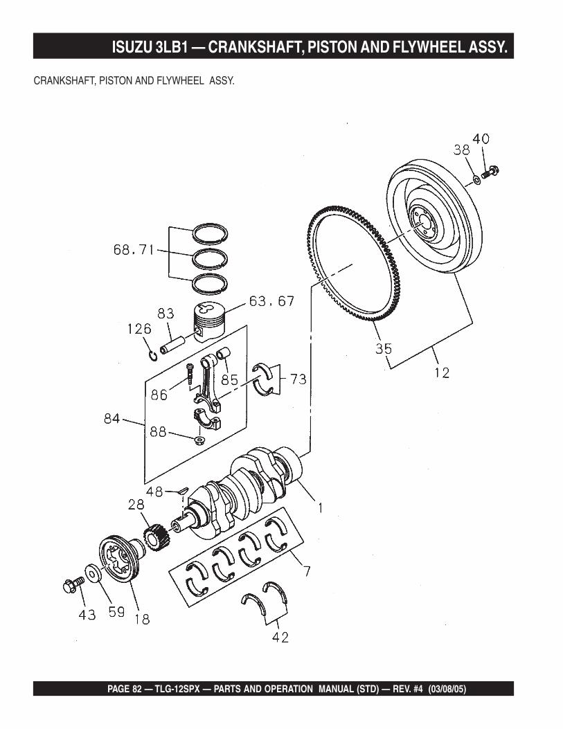
PAGE 82 — TLG-12SPX — PARTS AND OPERATION MANUAL (STD) — REV. #4 (03/08/05)
ISUZU 3LB1 — CRANKSHAFT, PISTON AND FLYWHEEL ASSY.
CRANKSHAFT, PISTON AND FLYWHEEL ASSY.

TLG-12SPX — PARTS AND OPERATION MANUAL (STD) — REV. #4 (03/08/05) — PAGE 83
ISUZU 3LB1 — CRANKSHAFT, PISTON AND FLYWHEEL ASSY.
CRANKSHAFT, PISTON AND FLYWHEEL ASSY.
NO PART NO PART NAME QTY. REMARKS1 8970405203 CRANKSHAFT 17 8970395820 METAL KIT 112 8971078930 FLYWHEEL ................................. 1 ........ INCL. ITEM W/*18 8971093721 PULLEY 128 8970345920 GEAR 135* 8944196021 RING GEAR 138 8970232680 WASHER 640 8941333281 BOLT 642 5115990023 WASHER 243 8943860790 BOLT 148 8942016410 WOODRUFF KEY 159 8941347920 WASHER 163 8971768880 PISTON 367 8970871050 PISTON, O/S=0.25 368 8970346090 RING SET ................................... 3 ........ APR. 1992 TO SEP. 1995
8971137620 RING SET ................................... 3 ........ OCT. 1995~71 8971412040 RING SET, O/X=0.25 373 5122710141 METAL SET 383 8944017510 PISTON PIN 384 8970200670 CONNECTOR ROD ASSY. ......... 3 ........ INCL. ITEMS W/#85# 8941375220 BUSHING 386# 8941075501 BOLT 688# 8942409020 NUT 6126 8944017501 SNAP RING 6
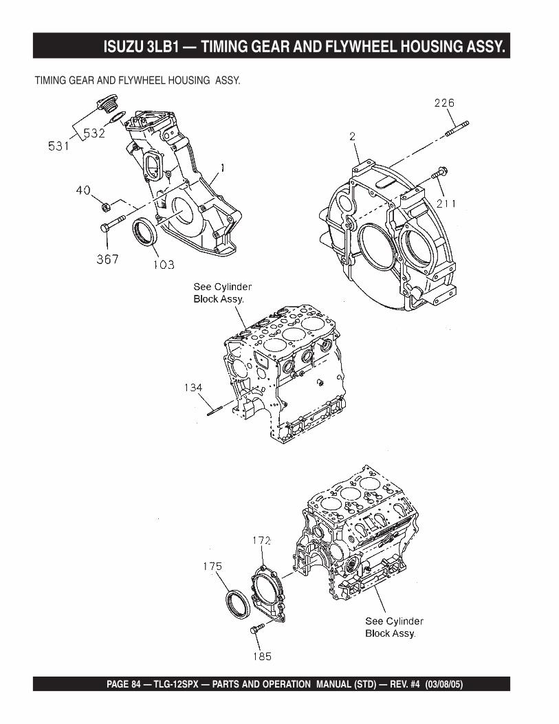
PAGE 84 — TLG-12SPX — PARTS AND OPERATION MANUAL (STD) — REV. #4 (03/08/05)
ISUZU 3LB1 — TIMING GEAR AND FLYWHEEL HOUSING ASSY.
TIMING GEAR AND FLYWHEEL HOUSING ASSY.

TLG-12SPX — PARTS AND OPERATION MANUAL (STD) — REV. #4 (03/08/05) — PAGE 85
ISUZU 3LB1 — TIMING GEAR AND FLYWHEEL HOUSING ASSY.
TIMING GEAR AND FLYWHEEL HOUSING ASSY.
NO. PART NO. PART NAME QTY. REMARKS1 8970851331 TIMING GEAR CASE 12 8970470233 FLYWHEEL HOUSING 140 0911502080 NUT 2103 5096250790 SEAL 1134 9041108600 STUD, M8X60 L=72 1
9041108500 STUD, M8X50 L=62 1172 8970447862 RETAINER 1175 5096250940 OIL SEAL 1185 0280806200 BOLT 6211 0281810250 BOLT 4226 8941277030 STUD 2367 0280808800 BOLT, M8X80 FLANGE 2
0280908600 BOLT, M8X60 FLANGE 6531 8944256852 OIL FILLER CAP............................ 1 ........... INCL. ITEM W/*532* 8941236231 CAP GASKET 1

PAGE 86 — TLG-12SPX — PARTS AND OPERATION MANUAL (STD) — REV. #4 (03/08/05)
ISUZU 3LB1 — INLET MANIFOLD ASSY.
INLET MANIFOLD ASSY.

TLG-12SPX — PARTS AND OPERATION MANUAL (STD) — REV. #4 (03/08/05) — PAGE 87
ISUZU 3LB1 — INLET MANIFOLD ASSY.
INLET MANIFOLD ASSY.
NO. PART NO. PART NAME QTY. REMARKS303 8970346140 AIR PIPE 1652 9041106160 DUCT STUD 2653 0911502060 NUT 2

PAGE 88 — TLG-12SPX — PARTS AND OPERATION MANUAL (STD) — REV. #4 (03/08/05)
ISUZU 3LB1 — EXHAUST MANIFOLD ASSY.
EXHAUST MANIFOLD ASSY.

TLG-12SPX — PARTS AND OPERATION MANUAL (STD) — REV. #4 (03/08/05) — PAGE 89
ISUZU 3LB1 — EXHAUST MANIFOLD ASSY.
EXHAUST MANIFOLD ASSY.
NO. PART NO. PART NAME QTY. REMARKS1 8970345881 EXHAUST MANIFOLD 12 8970376822 GASKET 115 0280808400 BOLT, M8X40 FLANGE 1
0280808700 BOLT, M8X70 FLANGE 116 9041108200 STUD 418 0911502080 NUT 284 8970420280 GASKET, EXHAUST PIPE 1

PAGE 90 — TLG-12SPX — PARTS AND OPERATION MANUAL (STD) — REV. #4 (03/08/05)
ISUZU 3LB1 — VENTILATION ASSY.
VENTILATION ASSY.

TLG-12SPX — PARTS AND OPERATION MANUAL (STD) — REV. #4 (03/08/05) — PAGE 91
ISUZU 3LB1 — VENTILATION ASSY.
VENTILATION ASSY.
NO. PART NO. PART NAME QTY. REMARKS13 9039104100 SCREW 432 5097070051 CLIP 443A 8971056801 PCV HOSE 143B 8971025191 PCV HOSE 143C 8971056811 PCV HOSE .................................................... 1 ........ OCT. 1993 TO OCT. 1997
8971025191 PCV HOSE ................................................... 1 ........ NOV. 1997~59 8941271440 HOSE CLIP 162 8942493171 CHECK VALVE 173 8942386100 CHECK VALVE CLIP ...................................... 1 ........ OCT. 1993 TO OCT. 1997
1097070870 CHECK VALVE CLIP ...................................... 1 ........ NOV. 1997~130A 8970833300 PCV PIPE 1130B 5111790520 PCV PIPE 3135 8943295490 VENTILATOR ASSY. 1

PAGE 92 — TLG-12SPX — PARTS AND OPERATION MANUAL (STD) — REV. #4 (03/08/05)
ISUZU 3LB1 — WATER PUMP AND CORROSION RESISTOR ASSY.
WATER PUMP AND CORROSION RESISTOR ASSY.

TLG-12SPX — PARTS AND OPERATION MANUAL (STD) — REV. #4 (03/08/05) — PAGE 93
ISUZU 3LB1 — WATER PUMP AND CORROSION RESISTOR ASSY.
WATER PUMP AND CORROSION RESISTOR ASSY.
NO. PART NO. PART NAME QTY. REMARKS2 8971632590 WATER PUMP ASSY. .......... 1 ..................... REPLACES 897069882124 0280808450 BOLT, M8X45 FLANGE 136 0280908600 BOLT, M8X60 FLANGE 2
0280808400 BOLT, M8X40 FLANGE 240 0911502080 NUT 242 9041108400 STUD 158 5096050050 HEATER PLUG 1144 1096050500 THERMOSTAT PLUG 1

PAGE 94 — TLG-12SPX — PARTS AND OPERATION MANUAL (STD) — REV. #4 (03/08/05)
THERMOSTAT AND HOUSING ASSY.
ISUZU 3LB1 — THERMOSTAT AND HOUSING ASSY.

TLG-12SPX — PARTS AND OPERATION MANUAL (STD) — REV. #4 (03/08/05) — PAGE 95
ISUZU 3LB1 — THERMOSTAT AND HOUSING ASSY.
THERMOSTAT AND HOUSING ASSY.
NO. PART NO. PART NAME QTY. REMARKS1 8943255131 THERMOSTAT ........................... 1 ................ APR. 1992 TO DEC. 1996
8971606540 THERMOSTAT ........................... 1 ................ JAN. 1997~49 8970958411 WATER OUTLET PIPE 150 0280808200 BOLT 264 8943259561 GASKET 1

PAGE 96 — TLG-12SPX — PARTS AND OPERATION MANUAL (STD) — REV. #4 (03/08/05)
ISUZU 3LB1 — FAN AND FAN BELT ASSY.
FAN AND FAN BELT ASSY.

TLG-12SPX — PARTS AND OPERATION MANUAL (STD) — REV. #4 (03/08/05) — PAGE 97
ISUZU 3LB1 — FAN AND FAN BELT ASSY.
FAN AND FAN BELT ASSY.
NO. PART NO. PART NAME QTY. REMARKS1 8970967090 COOLING FAN ....................... 1 ................... D=330-6-BLOW24A 0208006120 BOLT, M6X12 224B 0280808220 BOLT, M8X22 FLANGE 436 8970407640 BELT, L=826 ........................... 1 ................... APR. 1992 TO AUG. 1996
8971604370 BELT, L=815 ........................... 1 ................... SEPT. 1996~38 8970634001 FAN SPACER 180 5136741040 ADJUSTMENT PLATE 196 0280808200 BOLT 1112 8970384030 PULLEY, 1-GROOVE 1
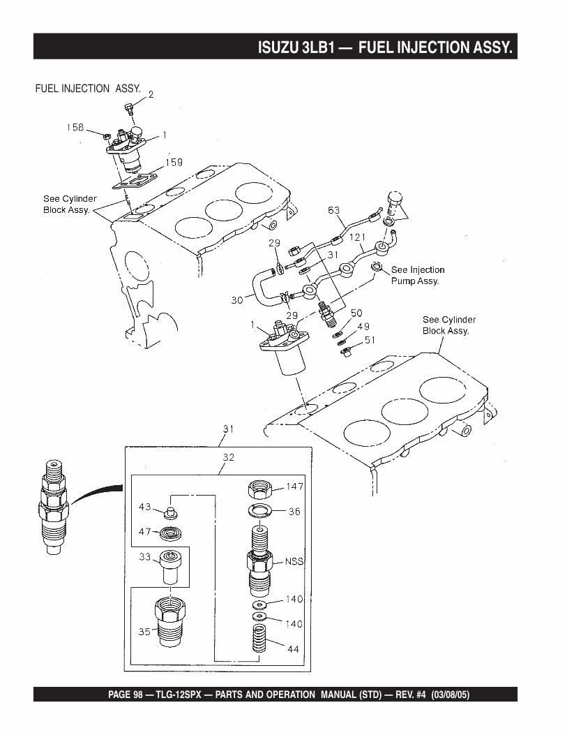
PAGE 98 — TLG-12SPX — PARTS AND OPERATION MANUAL (STD) — REV. #4 (03/08/05)
ISUZU 3LB1 — FUEL INJECTION ASSY.
FUEL INJECTION ASSY.

TLG-12SPX — PARTS AND OPERATION MANUAL (STD) — REV. #4 (03/08/05) — PAGE 99
ISUZU 3LB1 — FUEL INJECTION ASSY.
FUEL INJECTION ASSY.
NO. PART NO. PART NAME QTY. REMARKS1 8970345915 INJECTION PUMP ASSY. 32 0280808200 BOLT 629 5097070051 CLIP 230 8970408090 RUBBER HOSE 131 8970799760 NOZZLE ASSY. ......................... 3 ................ INCL. ITEMS W/*32* 8970908420 HOLDER ASSY. ........................ 3 ................ INCL. ITEMS W/#33* 8941305320 NOZZLE 335*# 8970846170 NUT 336*# 8941049930 GASKET 343*# 8941289630 SEAT 344*# 8941289640 SPRING 347*# 8970833580 SPACER 349 8941060403 WASHER 350 8942575920 GASKET 351 8941060551 SHIELD 363 8970346261 PIPE 1121 8970964020 FUEL PIPE 1140*# 8941769620 SHIM ......................................... 1 ................ T=0.1
8941769630 SHIM ......................................... 1 ................ T=0.28941769640 SHIM ......................................... 1 ................ T=0.38941769650 SHIM ......................................... 1 ................ T=0.48941769660 SHIM ......................................... 1 ................ T=0.58941769670 SHIM ......................................... 1 ................ T=0.528941769680 SHIM ......................................... 1 ................ T=0.548941769690 SHIM ......................................... 1 ................ T=0.568941769700 SHIM ......................................... 1 ................ T=0.588941769710 SHIM ......................................... 1 ................ T=0.6
147*# 8941290060 NUT 3158 0911502080 NUT 6159 8971263560 INJ. SHIM .................................. 1 ................ T=0.2; REPLACES 8970346152
8971263570 INJ. SHIM .................................. 1 ................ T=0.3; REPLACES 89703461628971263580 INJ. SHIM .................................. 1 ................ T-=0.4; REPLACES 89703461728971263590 INJ. SHIM .................................. 1 ................ T-=0.5; REPLACES 89703461828971263600 INJ. SHIM .................................. 1 ................ T=0.6; REPLACES 89703461928971263610 INJ. SHIM .................................. 1 ................ T=0.7; REPLACES 89703462028971263620 INJ. SHIM .................................. 1 ................ T=0.8; REPLACES 89703462128971263630 INJ. SHIM .................................. 1 ................ T=1.0; REPLACES 8970346228971263640 INJ. SHIM .................................. 1 ................ T=1.2; REPLACES 8970346232

PAGE 100 — TLG-12SPX — PARTS AND OPERATION MANUAL (STD) — REV. #4 (03/08/05)
ISUZU 3LB1 — FUEL FILTER AND BRACKET ASSY.
FUEL FILTER AND BRACKET ASSY.

TLG-12SPX — PARTS AND OPERATION MANUAL (STD) — REV. #4 (03/08/05) — PAGE 101
ISUZU 3LB1 — FUEL FILTER AND BRACKET ASSY.
FUEL FILTER AND BRACKET ASSY.
NO. PART NO. PART NAME QTY. REMARKS1 8971041891 FUEL FILTER ASSY. ................. 1 ................ INCL. ITEMS W/*2* 8970713480 FUEL FILTER ELEMENT KIT 126* 8941551830 GASKET 1

PAGE 102 — TLG-12SPX — PARTS AND OPERATION MANUAL (STD) — REV. #4 (03/08/05)
ISUZU 3LB1 — FUEL PUMP AND PIPE ASSY.
FUEL PUMP AND PIPE ASSY.

TLG-12SPX — PARTS AND OPERATION MANUAL (STD) — REV. #4 (03/08/05) — PAGE 103
ISUZU 3LB1 — FUEL PUMP AND PIPE ASSY.
FUEL PUMP AND PIPE ASSY.
NO. PART NO. PART NAME QTY. REMARKS1 8942411792 FUEL PUMP ASSY. .................. 1 ................ INCL. ITEMS W/*9* 9019106280 BOLT 234* 8942336550 RUBBER 257* 8942336570 WASHER 2215* 8942389070 COLLAR 2

PAGE 104 — TLG-12SPX — PARTS AND OPERATION MANUAL (STD) — REV. #4 (03/08/05)
ISUZU 3LB1 — OIL FILTER ASSY.
OIL FILTER ASSY.

TLG-12SPX — PARTS AND OPERATION MANUAL (STD) — REV. #4 (03/08/05) — PAGE 105
ISUZU 3LB1 — OIL FILTER ASSY.
OIL FILTER ASSY.
NO. PART NO. PART NAME QTY. REMARKS2 8943142633 OIL FILTER ELEMENT 1

PAGE 106 — TLG-12SPX — PARTS AND OPERATION MANUAL (STD) — REV. #4 (03/08/05)
ISUZU 3LB1 — OIL PUMP AND OIL STRAINER ASSY.
OIL PUMP AND OIL STRAINER ASSY.

TLG-12SPX — PARTS AND OPERATION MANUAL (STD) — REV. #4 (03/08/05) — PAGE 107
ISUZU 3LB1 — OIL PUMP AND OIL STRAINER ASSY.
OIL PUMP AND OIL STRAINER ASSY.
NO. PART NO. PART NAME QTY. REMARKS1 8970488094 OIL PUMP ASSY. ...................... 1 ................. INCL. ITEMS W/*13 0280808300 BOLT 423* 9081606160 PIN 226 8970448430 OIL PUMP PIPE 129* 0280806300 BOLT, M6X30 FLANGE 2
0280806500 BOLT, M6X50 FLANGE 151 8970439410 STRAINER AND PIPE ASSY. 161 0280808160 BOLT 185* 8971096790 GASKET 1102 1096234960 GASKET STRAINER 1119* 8942446550 RELIEF VALVE PLUG ............... 1 ................. APR. 1992 TO NOV. 1994
8941046150 RELIEF VALVE PLUG ............... 1 ................. DEC. 1994~120* 8941145120 RELIEF VALVE SPRING ........... 1 ................. APR. 1992 TO NOV. 1994
8971133320 RELIEF VALVE SPRING ........... 1 ................. DEC. 1994~121* 8942355671 VALVE 1132 5824100361 OIL PRESSURE SWITCH 1151* 8970448133 OIL PUMP SUB ASSY. 1

PAGE 108 — TLG-12SPX — PARTS AND OPERATION MANUAL (STD) — REV. #4 (03/08/05)
ISUZU 3LB1 — ELECTRICAL CONTROL ASSY.
ELECTRICAL CONTROL ASSY.

TLG-12SPX — PARTS AND OPERATION MANUAL (STD) — REV. #4 (03/08/05) — PAGE 109
ISUZU 3LB1 — ELECTRICAL CONTROL ASSY.
ELECTRICAL CONTROL ASSY.
NO. PART NO. PART NAME QTY. REMARKS1 8970489652 STARTER ASSY. 12 8970489701 GENERATOR ASSY. 14 0281812300 BOLT 27 9091114080 NUT 116 0280810700 BOLT 123 0911502100 NUT 146 8942481610 GLOW PLUG RELAY 189 8941679410 SWITCH 1177 8970701303 SOLENOID ASSY. .................... 1 ........... APR. 1992 TO JUL. 1998
8971830140 SOLENOID ASSY. .................... 1 ........... AUG. 1998~238 9095720140 GASKET 1292 9091505080 LOCK WASHER 1603 8941268220 SENSOR ASSY. 1613 8970912901 CONTROL UNIT ....................... 1 ........... APR. 1992 TO JUN. 1992
8971163140 CONTROL UNIT ....................... 1 ........... JUL. 1992 TO MAY 19968971461050 CONTROL UNIT ....................... 1 ........... JUN. 1996~
729 8970633010 SENSOR 1

PAGE 110 — TLG-12SPX — PARTS AND OPERATION MANUAL (STD) — REV. #4 (03/08/05)
ISUZU 3LB1 — STARTER COMP. ASSY.
STARTER COMP. ASSY.

TLG-12SPX — PARTS AND OPERATION MANUAL (STD) — REV. #4 (03/08/05) — PAGE 111
ISUZU 3LB1 — STARTER COMP. ASSY.
STARTER COMP. ASSY.
NO. PART NO. PART NAME QTY. REMARKS2 8970786480 CASE 113 581110110 YOKE 116 5811210310 ARMATURE 117A 5098000790 BEARING 117B 5098000400 BEARING 121 5811170070 SPRING 422 5811180220 HOLDER 123 581150340 COVER 127A 5811291820 BOLT 227B 5811291830 BOLT 231 8970786470 SWITCH 132 5811190290 COVER 141 5811291810 SCREW 243 5811291000 RETAINER 144 5811290990 ROLLER 546 5811230110 GEAR 147 5811290960 SPRING 148 5811290920 BALL 154 5811240031 CLUTCH 1114 5094000420 NUT 1
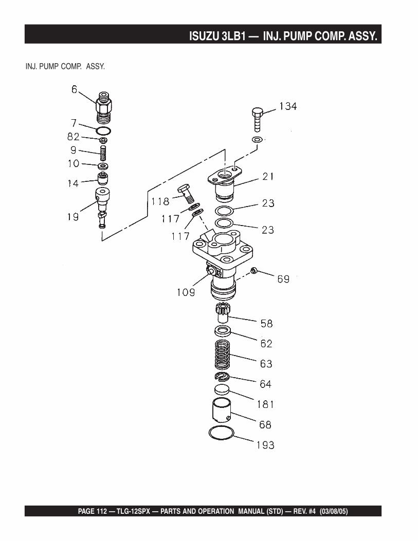
PAGE 112 — TLG-12SPX — PARTS AND OPERATION MANUAL (STD) — REV. #4 (03/08/05)
ISUZU 3LB1 — INJ. PUMP COMP. ASSY.
INJ. PUMP COMP. ASSY.

TLG-12SPX — PARTS AND OPERATION MANUAL (STD) — REV. #4 (03/08/05) — PAGE 113
ISUZU 3LB1 — INJ. PUMP COMP. ASSY.
INJ. PUMP COMP. ASSY.
NO. PART NO. PART NAME QTY. REMARKS6 8941327461 HOLDER 37 8941289150 GASKET 39 8941289110 SPRING 310 8941289120 GASKET 314 8970833460 VALVE 319 8970833450 PLUNGER ASSY. ...................... 3 ................ APR. 1992 TO FEB. 1995
8971386490 PLUNGER ASSY. ...................... 3 ................ MAR. 1995~21 8970833480 FLANGE 323 8943796920 GASKET 658 8941289230 SLEEVE 362 8941289200 SEAT 363 8941289190 SPRING 364 8941289210 SEAT 368 8941289160 TAPPET 369 8970833490 TAPPET GUIDE 382 8970833470 HOUSING PLUG 3109 8970833551 RACK 3117 8941445880 GASKET 6118 8943796880 BOLT 3134 8943796910 BOLT 6181 8941289310 SHIM ......................................... 1 ................ T=2.60
8941289320 SHIM ......................................... 1 ................ T=2.658941289330 SHIM ......................................... 1 ................ T=2.708941289340 SHIM ......................................... 1 ................ T=2.758941289350 SHIM ......................................... 1 ................ T=2.808941289360 SHIM ......................................... 1 ................ T=2.858941589370 SHIM ......................................... 1 ................ T=2.908941289380 SHIM ......................................... 1 ................ T=2.958941289390 SHIM ......................................... 1 ................ T=3.008941289400 SHIM ......................................... 1 ................ T=3.058941289410 SHIM ......................................... 1 ................ T=3.108941289420 SHIM ......................................... 1 ................ T=3.158941289430 SHIM ......................................... 1 ................ T=3.208941289440 SHIM ......................................... 1 ................ T=3.258941289450 SHIM ......................................... 1 ................ T=3.308941289460 SHIM ......................................... 1 ................ T=3.358941289470 SHIM ......................................... 1 ................ T=3.408941289480 SHIM ......................................... 1 ................ T=3.458941289490 SHIM ......................................... 1 ................ T=3.508941289500 SHIM ......................................... 1 ................ T=3.558941289510 SHIM ......................................... 1 ................ T=3.608941289520 SHIM ......................................... 1 ................ T=3.658941289530 SHIM ......................................... 1 ................ T=3.708941289540 SHIM ......................................... 1 ................ T=3.75

PAGE 114 — TLG-12SPX — PARTS AND OPERATION MANUAL (STD) — REV. #4 (03/08/05)
ISUZU 3LB1 — INJ. PUMP COMP. ASSY.
INJ. PUMP COMP. ASSY.

TLG-12SPX — PARTS AND OPERATION MANUAL (STD) — REV. #4 (03/08/05) — PAGE 115
ISUZU 3LB1 — INJ. PUMP COMP. ASSY.
NJ. PUMP COMP. ASSY.
NO. PART NO. PART NAME QTY. REMARKS
8941289550 SHIM ......................................... 1 ................ T=3.808941289560 SHIM ......................................... 1 ................ T=3.858941289570 SHIM ......................................... 1 ................ T=3.908941289580 SHIM ......................................... 1 ................ T=3.958941289590 SHIM ......................................... 1 ................ T=4.008941289600 SHIM ......................................... 1 ................ T=4.058941289610 SHIM ......................................... 1 ................ T=4.10
193 8970833500 SNAP RING 3

PAGE 116 — TLG-12SPX — PARTS AND OPERATION MANUAL (STD) — REV. #4 (03/08/05)
ISUZU 3LB1 — TIMING CHAIN CASE ASSY.
TIMING CHAIN CASE ASSY.

TLG-12SPX — PARTS AND OPERATION MANUAL (STD) — REV. #4 (03/08/05) — PAGE 117
ISUZU 3LB1 — TIMING CHAIN CASE ASSY.
TIMING CHAIN CASE ASSY.
NO. PART NO. PART NAME QTY. REMARKS1 8970456175 FLYWEIGHT 15 8970849771 SLEEVE .......................................1 ...................... APR. 1992 TO MAR. 1996
8971474890 SLEEVE .......................................1 ...................... APR. 1996~6A 9081608500 LEVER SHAFT 16B 9081605450 LEVER SHAFT 16C 8970164460 LEVER SHAFT 17 8971176720 COVER ........................................1 ...................... APR. 1992 TO JUN. 1996
8971062740 COVER ........................................1 ...................... JUL. 1996 TO JAN. 19978971617450 COVER ........................................1 ...................... FEB. 1997~
16 1079470020 LEVER PIN 118 8970346393 PLATE .........................................1 ...................... APR. 1992 TO JUN. 1996
8971485500 PLATE .........................................1 ...................... JUL. 1996~21 5095031320 GASKET SCREW 222A 9091114060 NUT 322B 9091104060 NUT 124 5094000480 NUT 125 5156690021 CAP 127 8970493280 LEVER 128 8971059061 LEVER .........................................1 ...................... APR. 1992 TO JUN. 1996
8971605721 LEVER .........................................1 ...................... JUL. 1996~29 1096230550 GASKET 230 8970169400 SPRING 131 5095031350 WASHER 232 9091105080 NUT 134 5157292391 EYE 135 987109759 MAIN SPRING 136 8970843250 START SPRING 137 8970169361 IDLE SPRING 139 8971097751 ANGLEICH KIT 140 8941304380 NUT 143 8970164492 LEVER 144 8970646881 COVER GASKET 145 8943695450 GEAR CASE BUSHING 146A 0280806200 BOLT 446B 0280806140 BOLT 146C 8970728300 BOLT 147 1157390020 LEAD SEAL 248 8913254460 LEAD SEAL WIRE 249 1096050190 COVER PLUG 150 8970345945 GUIDE LEVER 152 8971122650 GUIDE PIECE .............................1 ...................... REPLACES 897071806253 1097470020 GUIDE LEVER PIN 154 8971059100 TENSION LEVER 1

PAGE 118 — TLG-12SPX — PARTS AND OPERATION MANUAL (STD) — REV. #4 (03/08/05)
ISUZU 3LB1 — TIMING CHAIN CASE ASSY.
TIMING CHAIN CASE ASSY.

TLG-12SPX — PARTS AND OPERATION MANUAL (STD) — REV. #4 (03/08/05) — PAGE 119
ISUZU 3LB1 — TIMING CHAIN CASE ASSY.
TIMING CHAIN CASE ASSY.
NO. PART NO. PART NAME QTY. REMARKS55 8970346383 SHIFTER 156 9082136250 SHAFT 157 9091854040 SNAP RING 158 8970624222 FLOATING LEVER .....................1 ...................... APR. 1992 TO JUN. 1996
8971485480 FLOATING LEVER .....................1 ...................... JUL. 1996~59 1096050500 PLUG 160 8971062050 LINK.............................................1 ...................... DEC. 1993 TO APR. 1995
8971062051 LINK.............................................1 ...................... MAY 1995~61 8970395841 SCREW 162 8970164410 SCREW 163A 9091605040 IDLE WASHER 163B 9091607040 IDLE WASHER 164 9091854030 SNAP RING 165 8943176381 SCREW 266 9091505080 LOCK WASHER 167 9081604360 PIN 169 8970837140 SET SPRING 170 8970392644 COVER 171 5111290060 SEALING CUP 172 9095612530 COVER GASKET 173 8970395461 SPRING 174 9091105080 NUT 175 8970388021 BUSHING 176 8944546150 CUP 178 8971059090 ADJUSTER 1

PAGE 120 — TLG-12SPX — PARTS AND OPERATION MANUAL (STD) — REV. #4 (03/08/05)
ISUZU 3LB1 —AIR CLEANER ASSY.
AIR CLEANER ASSY.

TLG-12SPX — PARTS AND OPERATION MANUAL (STD) — REV. #4 (03/08/05) — PAGE 121
ISUZU 3LB1 — AIR CLEANER ASSY.
AIR CLEANER ASSY.
NO. PART NO. PART NAME QTY. REMARKS1 8941251130 CLEANER ASSY. ..................... 1 .................. INCL. ITEMS W/*2* 9142170620 WING NUT 16* 5142150140 AIR CLEANER FILTER 189* 9142191410 INDICATOR 190* 8941591510 CUP 191* 5142170040 CLAMP 1139 8970497220 AIR CLEANER BAND 2

PAGE 122 — TLG-12SPX — PARTS AND OPERATION MANUAL (STD) — REV. #4 (03/08/05)
ISUZU 3LB1 — SWITCH AND RELAY ASSY.
SWITCH AND RELAY ASSY.

TLG-12SPX — PARTS AND OPERATION MANUAL (STD) — REV. #4 (03/08/05) — PAGE 123
ISUZU 3LB1 — SWITCH AND RELAY ASSY.
SWITCH AND RELAY ASSY.
NO. PART NO. PART NAME QTY. REMARKS58 8970444180 IGNITION SWITCH ................... 1 ................ INCL. ITEMS W/*288 5825500290 SAFETY RELAY 1424 5825500290 RELAY 2434* 1823160070 STARTER SWITCH KEY 1

PAGE 124 — TLG-12SPX — PARTS AND OPERATION MANUAL (STD) — REV. #4 (03/08/05)
PAYMENT TERMS
Terms of payment for parts are net 10 days.
FREIGHT POLICY
All parts orders will be shipped collect orprepaid with the charges added to the invoice.All shipments are F.O.B. point of origin.Multiquip’s responsibility ceases when asigned manifest has been obtained from thecarrier, and any claim for shortage or damagemust be settled between the consignee and thecarrier.
MINIMUM ORDER
The minimum charge for orders from Multiquipis $15.00 net. Customers will be asked forinstructions regarding handling of orders notmeeting this requirement.
RETURNED GOODS POLICY
Return shipments will be accepted and creditwill be allowed, subject to the followingprovisions:
1. A Returned Material Authorization mustbe approved by Multiquip prior to shipment.
2. To obtain a Return Material Authorization,a list must be provided to Multiquip PartsSales that defines item numbers,quantities, and descriptions of the itemsto be returned.
a. The parts numbers and descriptionsmust match the current parts pricelist.
b. The list must be typed or computergenerated.
c. The list must state the reason(s) forthe return.
d. The list must reference the salesorder(s) or invoice(s) under whichthe items were originally purchased.
e. The list must include the name andphone number of the personrequesting the RMA.
3. A copy of the Return MaterialAuthorization must accompany the returnshipment.
PRICING AND REBATES
Prices are subject to change without priornotice. Price changes are effective on a specificdate and all orders received on or after that datewill be billed at the revised price. Rebates forprice declines and added charges for priceincreases will not be made for stock on handat the time of any price change.
Multiquip reserves the right to quote and selldirect to Government agencies, and to OriginalEquipment Manufacturer accounts who useour products as integral parts of their ownproducts.
SPECIAL EXPEDITING SERVICE
A $20.00 to $50.00 surcharge will be added tothe invoice for special handling including busshipments, insured parcel post or in caseswhere Multiquip must personally deliver theparts to the carrier.
LIMITATIONS OF SELLER’S LIABILITY
Multiquip shall not be liable here under fordamages in excess of the purchase price of theitem with respect to which damages areclaimed, and in no event shall Multiquip beliable for loss of profit or good will or for anyother special, consequential or incidentaldamages.
LIMITATION OF WARRANTIES
No warranties, express or implied, are madein connection with the sale of parts or tradeaccessories nor as to any engine notmanufactured by Multiquip. Such warrantiesmade in connection with the sale of new,complete units are made exclusively by astatement of warranty packaged with suchunits, and Multiquip neither assumes notauthorizes any person to assume for it anyother obligation or liability whatever inconnection with the sale of its products. A partfrom such written statement of warranty, thereare no warranties, express, implied or statutory,which extend beyond the description of theproducts on the face hereof.
4. Freight is at the sender’s expense. Allparts must be returned freight prepaid toMultiquip’s designated receiving point.
5. Parts must be in new and resalablecondition, in the original Multiquip package(if any), and with Muiltiquip part numbersclearly marked.
6. The following items are not returnable:
a. Obsolete parts. (If an item is listedin the parts price book as beingreplaced by another item, it isobsolete.)
b. Any parts with a limited shelf life(such as gaskets, seals, “O” rings,and other rubber parts) that werepurchased more than six monthsprior to the return date.
c. Any line item with an extended dealernet price of less than $5.00.
d. Special order items.
e. Electrical components.
f. Paint, chemicals, and lubricants.
g. Decals and paper products.
h. Items purchased in kits.
7. The sender will be notified of any materialreceived that is not acceptable.
8. Such material will be held for 5 workingdays from notification, pendinginstructions. If a reply is not receivedwithin 5 days, the material will be returnedto the sender at his expense.
9. Credit on returned parts will be issued atdealer net price at time of the originalpurchase, less a 15% restocking charge.
10. In cases where an item is accepted forwhich the original purchase documentcan not be determined, the price will bebased on the list price that was effectivetwelve months prior to the RMA date.
11. Credit issued will be applied to futurepurchases only.
Effective: July 1, 2000 TERMS AND CONDITIONS OF SALE — PARTS

TLG-12SPX — PARTS AND OPERATION MANUAL (STD) — REV. #4 (03/08/05) — PAGE 125
NOTE PAGE

© C
OP
YR
IGH
T 2
001,
MU
LTIQ
UIP
IN
C.
PARTS AND OPERATION MANUAL
MULTIQUIP INC..... PARTS DEPARTMENT:18910 WILMINGTON AVE. 800-427-1244CARSON, CALIFORNIA 90746 FAX: 800-672-7877310-537-3700 SERVICE DEPARTMENT:800-421-1244 800-835-2551FAX: 310-537-3927 FAX: 310-638-8046E-mail:[email protected] • www:multiquip.com
PARTS AND OPERATION MANUAL
HERE'S HOW TO GET HELPPLEASE HAVE THE MODEL AND SERIAL NUMBERON-HAND WHEN CALLING
PARTS DEPARTMENT800/427-1244 or 310/537-3700FAX: 800/672-7877 or 310/637-3284
SERVICE DEPARTMENT800/835-2551 or 310/537-3700FAX: 310/638-8046
WARRANTY DEPARTMENT800/835-2551 or 310/537-3700FAX: 310/638-8046
MAIN800/421-1244 or 310/537-3700FAX: 310/537-3927