mtech r 90 d-c
TRANSCRIPT
ORIGINAL INSTRUCTIONS DOC. 10082602 - Ver. AA - 09-2018
PROFESSIONAL SCRUBBING MACHINES
USE AND MAINTENANCE MANUAL
MTECH R 90 D-C

MAIN MACHINE COMPONENTS
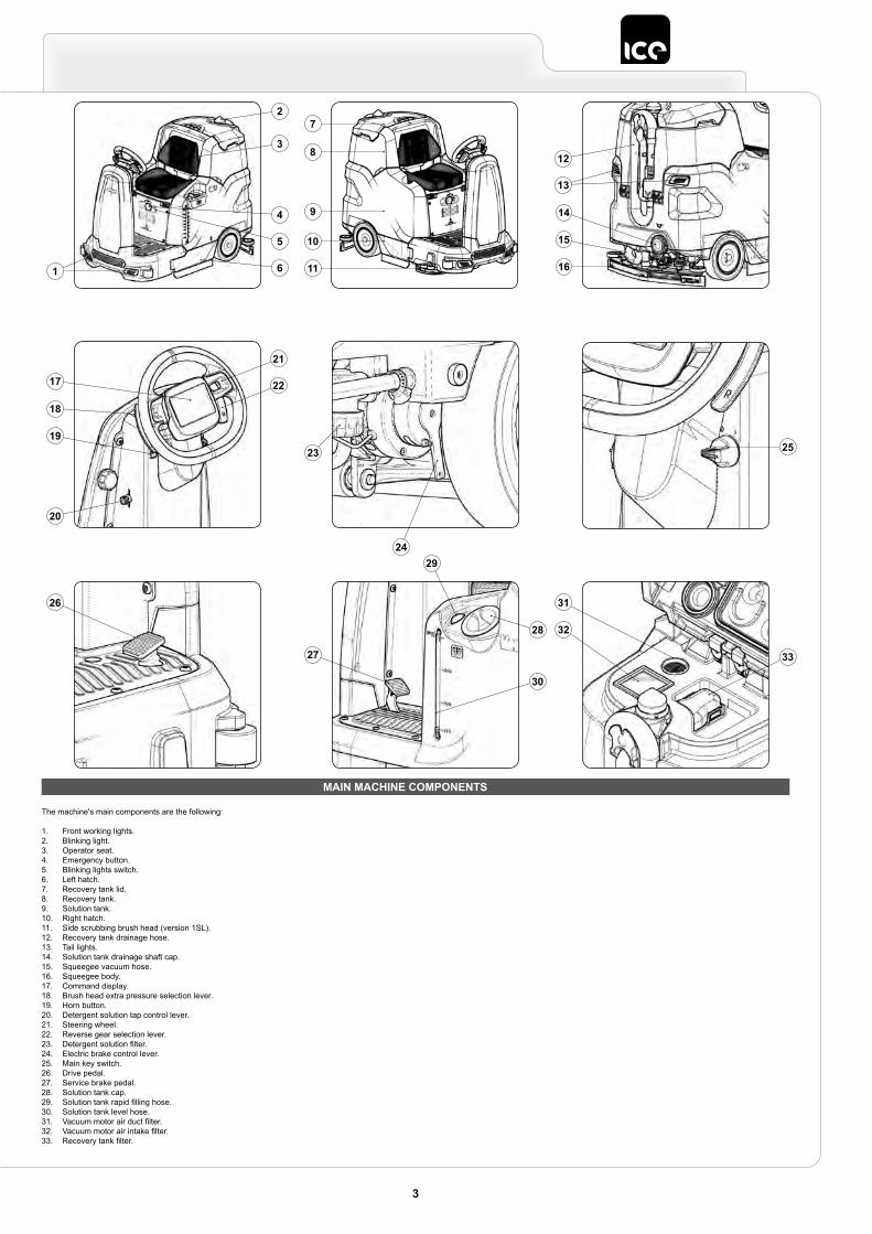
The machine's main components are the following:
1. Front working lights.2. Blinking light.3. Operator seat.4. Emergency button.5. Blinking lights switch.6. Left hatch.7. Recovery tank lid.8. Recovery tank.9. Solution tank.10. Right hatch.11. Side scrubbing brush head (version 1SL).12. Recovery tank drainage hose.13. Tail lights.14. Solution tank drainage shaft cap.15. Squeegee vacuum hose.16. Squeegee body.17. Command display.18. Brush head extra pressure selection lever.19. Horn button.20. Detergent solution tap control lever.21. Steering wheel.22. Reverse gear selection lever.23. Detergent solution filter.24. Electric brake control lever.25. Main key switch.26. Drive pedal.27. Service brake pedal.28. Solution tank cap.29. Solution tank rapid filling hose.30. Solution tank level hose.31. Vacuum motor air duct filter.32. Vacuum motor air intake filter.33. Recovery tank filter.
3
11
10
9
8
72
3
6
5
4
1 16
15
14
13
12
22
21
20
19
18
17
24
23 25
26
29
28
30
27 33
31
32

CONTENTS
MAIN MACHINE COMPONENTS ..............................................3CONTENTS ................................................................................4GENERAL SAFETY REGULATIONS ........................................5
RECHARGING THE BATTERIES ....................................................... 5USING THE MACHINE ....................................................................... 6DEACTIVATION OF THE MACHINE ................................................... 8MAINTENANCE .................................................................................. 9TRANSPORT .................................................................................... 10
SYMBOLS USED IN THE MANUAL .......................................11PURPOSE AND CONTENT OF THE MANUAL ......................11TARGET GROUP .....................................................................11PRESERVATION OF THE USER ............................................11ON CONSIGNMENT OF THE MACHINE ................................11INTRODUCTORY COMMENT .................................................11IDENTIFICATION DATA ...........................................................11TECHNICAL DESCRIPTION ...................................................11INTENDED USE .......................................................................11SAFETY ...................................................................................11REGULATIONS ........................................................................11SERIAL NUMBER PLATE .......................................................11TECHNICAL DATA ..................................................................12BRUSH TYPE ..........................................................................12BRUSH TYPE ..........................................................................13SYMBOLS USED ON THE MACHINE ....................................14LABELS USED ON THE MACHINE ........................................14SYMBOLS USED ON THE CONTROL DISPLAY ...................15PREPARATION OF MACHINE ................................................15
HANDLING THE PACKAGED MACHINE ......................................... 15HOW TO UNPACK THE MACHINE .................................................. 15HOW TO MOVE THE MACHINE ...................................................... 16MACHINE SAFETY ........................................................................... 16BATTERY MAINTENANCE AND DISPOSAL .................................... 16INSERTING THE BATTERIES INTO THE MACHINE ....................... 16CONNECTING BATTERIES TO THE MACHINE .............................. 17RECHARGING THE BATTERIES ..................................................... 17FILLING THE SOLUTION TANK ....................................................... 17DETERGENT SOLUTION ................................................................. 18ADJUSTMENT OF DRIVING POSITION .......................................... 18INSERTING WATER SYSTEM FILTER ............................................ 18ASSEMBLING THE BRUSH HEAD BRUSHES (SCRUBBING VERSION) ......................................................................................... 18FITTING LATERAL BRUSH 1SL (SCRUBBING ) ............................. 18FITTING THE BRUSH HEAD BODY SIDE SPLASHGUARDS (WASHING VERSION) ...................................................................... 19ASSEMBLING THE BRUSH HEAD BRUSHES (SWEEPING VERSION) ................................................................... 19ASSEMBLING SIDE BRUSH 2SL (SWEEPING VERSION) ............. 19ASSEMBLING THE SQUEEGEE BODY........................................... 19
PREPARING TO WORK ..........................................................19WORK ......................................................................................20
DS SELECTOR (DRIVE SELECT) .................................................... 20TRANSFER ....................................................................................... 20SCRUBBING WITHOUT DRYING .................................................... 21DRYING ............................................................................................. 21SCRUBBING WITH DRYING ............................................................ 22ECO MODE ....................................................................................... 22MANUAL MODE ................................................................................ 23PROGRAM ZONE MODE ................................................................. 23REVERSE GEAR .............................................................................. 23BUZZER ............................................................................................ 24EXTRA BRUSH HEAD PRESSURE ................................................. 24MAINTENANCE LIGHTS (OPTIONAL) ............................................. 24WORKING HEADLIGHTS ................................................................. 24
DETERGENT SOLUTION RECYCLING SYSTEM (OPTIONAL) ..... 24AUTOMATIC REQUEST FOR TECHNICAL ASSISTANCE (OPTIONAL) ..................................................................................... 24AUTOMATIC DETERGENT DOSING SYSTEM (OPTIONAL) .......... 24TUTORIAL ......................................................................................... 25REAR VIDEO CAMERA (OPTIONAL) .............................................. 25EMERGENCY BUTTON .................................................................... 25HOUR METER .................................................................................. 25BATTERY CHARGE LEVEL INDICATOR ......................................... 25ACTIVATING THE SIDE BRUSH ...................................................... 25OVERFLOW DEVICE ....................................................................... 26ALARM SCREEN .............................................................................. 26VACUUM WAND KIT (OPTIONAL) ................................................... 26BRAKING CONTROL ........................................................................ 26
AT THE END OF THE WORK ..................................................26RECOMMENDED MAINTENANCE OPERATIONS ................27
DRAINING THE RECOVERY TANK ................................................. 27EMPTYING THE DEBRIS HOPPER (SWEEPING VERSION) ......... 27CLEANING THE SQUEEGEE BODY................................................ 27CLEANING THE BRUSH HEAD BRUSHES (SCRUBBING VERSION) ................................................................. 28CLEANING THE BRUSH HEAD BRUSHES (SWEEPING VERSION) ................................................................... 29CLEANING THE LATERAL BRUSH (SCRUBBING VERSION) ........ 29CLEANING THE LATERAL BRUSH (SWEEPING VERSION) .......... 30CLEANING THE RECOVERY TANK FILTERS ................................. 30CLEANING THE RECYCLE FILTER (FLR VERSIONS) ................... 31EMPTYING THE SOLUTION TANK .................................................. 32CLEANING THE WATER SYSTEM FILTER ..................................... 32CLEANING THE DEBRIS HOPPER (SWEEPING VERSION) ......... 32CLEANING THE VACUUM TUBE ..................................................... 33
EXTRAORDINARY MAINTENANCE .......................................34REPLACING THE SQUEEGEE BODY RUBBER BLADES .............. 34REPLACING THE BRUSH HEAD SPLASH GUARD ........................ 34REPLACING THE SIDE SQUEEGEE SPLASHGUARD RUBBER BLADES ............................................................................ 34FILLING BRAKING SYSTEM OIL BASIN ......................................... 34
ADJUSTMENT INTERVENTIONS ...........................................35ADJUSTING THE SQUEEGEE BODY'S RUBBER BLADES ........... 35ADJUSTING BRUSH HEAD BODY SIDE SPLASHGUARDS .......... 35ADJUSTING THE SIDE BRUSH (SWEEPING VERSION) ............... 35
DISPOSAL ...............................................................................36EC DECLARATION OF CONFORMITY ..................................36TROUBLESHOOTING .............................................................37BROWSING THE COMMAND DISPLAY MENU .....................39
CHANGING THE LANGUAGE OF THE GRAPHICS INTERFACE ... 39CHANGING THE TYPE OF HOUR METER DISPLAYED ................ 39RESETTING THE PARTIAL HOUR METER ..................................... 39ACTIVATION OR DEACTIVATION OF THE WORK ZONES ............ 39ACTIVATION OR DEACTIVATION OF THE MANUAL FUNCTION .. 40CHANGING THE PROGRAM ZONE PARAMETERS ....................... 40MONITOR FUNCTION ...................................................................... 40VIEWING THE LIST OF ALARMS .................................................... 41LOCK ALARMS ................................................................................. 41MANUAL RESET ALARMS ............................................................... 42AUTOMATIC RESET ALARMS ......................................................... 42
4
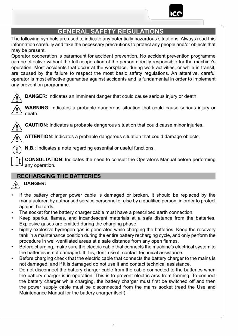
GENERAL SAFETY REGULATIONSThe following symbols are used to indicate any potentially hazardous situations. Always read this information carefully and take the necessary precautions to protect any people and/or objects that may be present.Operator cooperation is paramount for accident prevention. No accident prevention programme can be effective without the full cooperation of the person directly responsible for the machine's operation. Most accidents that occur at the workplace, during work activities, or while in transit, are caused by the failure to respect the most basic safety regulations. An attentive, careful operator is most effective guarantee against accidents and is fundamental in order to implement any prevention programme.
DANGER: Indicates an imminent danger that could cause serious injury or death.
WARNING: Indicates a probable dangerous situation that could cause serious injury or death.
CAUTION: Indicates a probable dangerous situation that could cause minor injuries.
ATTENTION: Indicates a probable dangerous situation that could damage objects.
N.B.: Indicates a note regarding essential or useful functions.
CONSULTATION: Indicates the need to consult the Operator's Manual before performing any operation.
RECHARGING THE BATTERIESDANGER:
• If the battery charger power cable is damaged or broken, it should be replaced by the manufacturer, by authorised service personnel or else by a qualified person, in order to protect against hazards.
• The socket for the battery charger cable must have a prescribed earth connection.• Keep sparks, flames, and incandescent materials at a safe distance from the batteries.
Explosive gases are emitted during the charging phase.• highly explosive hydrogen gas is generated while charging the batteries. Keep the recovery
tank in a maintenance position during the entire battery recharging cycle, and only perform the procedure in well-ventilated areas at a safe distance from any open flames.
• Before charging, make sure the electric cable that connects the machine's electrical system to the batteries is not damaged. If it is, don't use it; contact technical assistance.
• Before charging check that the electric cable that connects the battery charger to the mains is not damaged, and if it is damaged do not use it and contact technical assistance.
• Do not disconnect the battery charger cable from the cable connected to the batteries when the battery charger is in operation. This is to prevent electric arcs from forming. To connect the battery charger while charging, the battery charger must first be switched off and then the power supply cable must be disconnected from the mains socket (read the Use and Maintenance Manual for the battery charger itself).
5
WARNING:
• Do not use incompatible battery chargers since they could damage the batteries and potentially cause a fire.
• The batteries emit hydrogen gas. This gas can cause explosions or fires. Keep a safe distance from flames or sparks. Keep the recovery tank open for the duration of the battery recharging.
• the room used to recharge the batteries must be adequately ventilated to prevent the accumulation of gases that leak from batteries.
• For versions with a battery charger on-board, before charging make sure that the frequency and the voltage indicated in the battery charger user manual, (enclosed with the machine documentation) match the mains voltage.
• Keep the battery charger's cable at a safe distance from any hot surfaces.• Never smoke in the machine's vicinity while the batteries are charging.• Carefully read the user manual of the battery charger you want to use before recharging.
USING THE MACHINEDANGER:
• The machine may be used by children over the age of 8 and by people with limited physical, sensorial or mental capacity, or people without experience or the required knowledge, as long as they are supervised or have been instructed about safe machine use and the inherent dangers. Children must not play with the machine. The cleaning and maintenance that should be carried out by the user should not be done by unsupervised children.
• In the event of danger, take prompt action by pressing the emergency button near the operator's seat.
• Never collect gases, explosive/inflammable liquids or powders, nor acids and solvents! These include gasoline, paint thinners and fuel oil (which, when mixed with the vacuum air, can form explosive vapours or mixtures), and also non-diluted acids and solvents, acetones, aluminium and magnesium powders. These substances may also corrode the materials used to construct the machine.
• If the machine is used in dangerous areas (e.g. petrol stations), the relative safety standards must be observed. It is forbidden to use the machine in environments with a potentially explosive atmosphere.
• Never use the machine with the electro-magnetic brake disengaged.
WARNING:
• The machine must be exclusively used by authorised, trained personnel.• Do not use the machine on surfaces with a slope greater than the one indicated on the serial
number plate.• The machine is not suitable for cleaning rough or uneven floors. Do not use the machine on
slopes.• In the event of a fire, use a powder extinguisher. Do not use water.• Adapt the speed to the adhesion conditions.• In order to prevent the unauthorised use of the machine, the power supply must be
disconnected: switch the machine off using the main switch (by removing the key from the block) and disconnect the battery's connector from the electrical system's connector.
• Do not use the machine without the requisite knowledge and authorisations.
6
• Do not use the machine if you have not read and understood the following user manual.• Do not use the machine under the influence of alcohol or drugs.• Do not use the machine when using a mobile phone or other types of electronic devices.• Do not use the machine if it is not working correctly.• Do not use the machine in areas where there are inflammable vapours or liquids or combustible
powders.• Do not use the machine in areas that are too dark to see the controls or operate the machine
safely, unless the work lights or the front headlights are on.
CAUTION:
• Children must be supervised to ensure they do not play with the machine.• During the working of the machine, pay attention to other people and especially to children.• The machine must only be powered with a voltage equal to that shown on the serial number
plate.• Read the labels on the machine carefully. Do not cover them for any reason, and replace them
immediately if they become damaged.• The machine must only be used and stored in an enclosed or covered environment.• The machine must not be used or stored outdoors in damp conditions or directly exposed to
rain.• The machine does not cause harmful vibrations.• Use the machine only in the way described in this manual.• Do not pick up anything that is burning or smouldering, like cigarettes, matches or glowing
embers.• Reduce speed on slopes and dangerous corners.• Reduce speed before making a turn.• Keep all parts of your body inside when the machine is moving.• Be careful when reversing.• Do not transport passengers.• Always follow the instructions for mixing, use and disposal on the containers of the chemical
substances.
ATTENTION:
• The machine is not suitable for use by people (including children) with limited physical, sensorial or mental, or by people who have no experience or the required knowledge, unless they are supervised or after they have been given instruction regarding using the machine by a person responsible for their safety.
• If the machine is to be used in the presence of other individuals, aside from the operator, the beacon light must be utilized.
• Always take appropriate measures to protect any individuals and/or objects that may be present while using this machine.
• Be careful to avoid collisions with shelving or scaffolding, above all if there is a risk of objects falling from heights.
• Do not place any liquid containers on the machine.• The machine must only be used under temperature conditions ranging from +0 °C to +40 °C.• When using detergents to clean the flooring, always follow the instructions and respect the
warnings indicated on the containers' labels.
7
• Always use appropriate gloves and protective equipment when handling the detergents used to clean the floor.
• Do not use the machine as a means of transport.• Avoid working with the brushes when the machine is standing still, so as not to damage the
floor.• In the event of a fire, use a powder fire extinguisher if possible, and avoid the use of water.• Do not allow any objects to penetrate into the machine's openings. Do not use the machine is
the openings are obstructed.• Keep the machine's openings free of any dust, lint, hairs, or any other foreign materials that
could reduce the airflow.• Do not remove or alter any labels affixed to the machine.• This machine has not been approved for use on public streets or roadways.• Only use the brushes and pad holders that have been supplied along with the machine or those
specified in the Operator's Manual. The use of other brushes or felt pads could compromise the machine's safety conditions.
• Before starting to work check that there are no leaks.• Before starting to work check that all the safety devices have been installed and are working
correctly.• Take all due precautions so that hair, jewellery, loose clothing do not get entangled in the
machine's moving parts.• Only use the machine in well-lit areas.
DEACTIVATION OF THE MACHINEWARNING:
• Always protect the machine against sunlight, rain, and other atmospheric agents, both while it is stationary and while it is in function. Store the machine in a dry, sheltered place: this machine is only designed for use under dry conditions, and must not be used or stored outdoors under humid conditions.
• Do not park the machine near combustible materials, powders, gases or liquids.• Stop the machine on a flat surface.• Switch off the machine and remove the key from the instrument panel.• If the machine is left unattended, it must be protected from any accidental movements
CAUTION:
• In order to prevent the unauthorised use of the machine, the power supply must be disconnected: switch the machine off using the main switch (by removing the key from the block) and disconnect the battery's connector from the electrical system's connector.
ATTENTION:
• The machine must only be stored under temperature conditions ranging from +0 °C to +40 °C. The humidity level must be between 30% and 95%.
8
MAINTENANCEDANGER:
• In order to avoid short-circuits when working in the vicinity of electrical components, do the following: avoid the use of non-insulated tools; do not place or allow metallic objects to fall upon the electrically powered components; remove any rings, watches and/or clothing with metallic parts that might come into contact with the electrically powered components.
• do not work underneath the raised machine without adequate fixed safety supports.
WARNING:
• Read all the relevant instructions carefully before performing any maintenance/repair operations.
• If the machine does not work properly, check this is not caused by failure to carry out routine maintenance. Otherwise, ask for intervention of the authorised technical assistance centre.
• Restore all electrical connections after any maintenance interventions.
CAUTION:
• When doing maintenance work, switch off the machine using the main switch. Remove the key from the instrument panel and remove the battery connector from the electrical system connector.
• Avoid contact with moving parts. Do not wear loose clothing or jewellery and tie long hair back.• Block the wheels before lifting the machine.• Lift the machine with equipment that can sustain the weight to be lifted.
ATTENTION:
• Never tamper with the machine's protection devices for any reason; always follow the supplied routine maintenance instructions scrupulously.
• The electro-magnetic brake must be released in order to move the machine manually. Once the manual movement operations have been completed, the electro-magnetic brake must be re-engaged. Never use the machine with the electro-magnetic brake disengaged.
• If the machine needs to be pushed for maintenance purposes (batteries absent; discharged batteries; etc.), never go faster than 4km/h.
• If any issues are encountered while using the machine, check to make sure that these are not due to a lack of proper maintenance. Otherwise, request the intervention of authorized personnel or an Authorized service centre.
• If any parts need to be replaced, always request ORIGINAL spare parts from an authorized Dealer or Retailer.
• In order to ensure the machine's safety and proper functionality, always have the scheduled maintenance interventions (specified in the appropriate section of this Manual) performed by authorized personnel or by an authorized Service Centre.
• Do not clean the machine with direct or pressurized jets of water, or with corrosive substances.• If lead batteries (WET) have been installed on the machine, avoid tilting it beyond 86° in
relation to the horizontal plane, as this could cause the highly corrosive liquid to leak out of the batteries.
• Avoid contact with the battery acid.• Keep all metal objects away from the batteries.
9
• Use a non-conductive device for removing the battery.• Use a hoist and suitable equipment when lifting the batteries.• The battery must be installed by qualified personnel.• Always observe the safety measures of the site regarding removing the battery.• Remove the batteries if the machine needs to be tilted in order to perform maintenance
procedures.• Have the machine checked by an authorised technical assistance centre every year.• When disposing of consumable materials, observe the laws and regulations in force. Once
the machine has reached the end of its service life, the materials contained within it must be disposed of in an appropriate manner, keeping in mind that the machine itself has been built using fully recyclable materials.
• Do not push or tow the machine without an operator on the seat who can control the machine.• Do not wash the machine with pressurised water or wet the machine near electrical components.• All repairs must be carried out by qualified personnel.• Do not physically change the design characteristics of the machine.• Use spare parts supplied by ICE or by ICE service centres.• Wear personal protective equipment as required and as suggested in the manual.
TRANSPORTWARNING:
• Drain both tanks before transport.• Bring both the squeegee and the brushes to a working position before securing the machine
to the transport vehicle.• Use a ramp, a truck or a trailer that can support the weight of the machine and the operator.• To place the machine on the transport vehicle use a pulley. Do not drive the machine on or off
a truck or trailer.• The ramp for placing the machine on the transport vehicle should have such a slope that the
machine does not get damaged.• Engage the parking brake after loading the machine onto the transport vehicle.• Secure the device according to the directives in force in the country of use, so that it cannot
slide or tip over when being transported.
ATTENTION:
• Use caution when moving the machine under temperatures below freezing. The water contained in the water recovery tank or in the pipes could freeze, and could seriously damage the machine itself.
10

The descriptions contained in this document are not binding. The company therefore reserves the right to make any modifications at any time to elements, details, or accessory supply, as considered necessary for reasons of improvement or manufacturing/commercial requirements. The reproduction, even partial, of the text and drawings contained in this document is prohibited by law.
The company reserves the right to make any technical and/or supply modifications. The images are shown as reference only and are not binding as to the actual design and/or equipment.
SYMBOLS USED IN THE MANUAL
PURPOSE AND CONTENT OF THE MANUALThe aim of this manual is to provide customers with all the information needed to use the machine in the safest, most appropriate and most autonomous way. This includes information concerning technical aspects, safety, operation, downtime, maintenance, spare parts and scrapping. The operators and qualified technicians must carefully read the instructions in this manual before carrying out any operations on the machine. If in doubt about the correct interpretation of instructions, contact your nearest Customer Service Centre to obtain the necessary clarifications.
TARGET GROUPThis manual is written both for operators and for qualified machine maintenance technicians. Operators must not perform operations that should be carried out by qualified technicians. The manufacturer is not liable for damages resulting from failure to comply with this veto.
PRESERVATION OF THE USERThe Use and Maintenance Manual must be stored in its special pouch close to the machine, protected from liquids and anything else that could compromise its legibility.
ON CONSIGNMENT OF THE MACHINEWhen the machine is consigned to the customer, an immediate check must be performed to ensure all the material mentioned in the shipping documents has been received, and also to check the machine has not suffered damage during transportation. If this is the case, the carrier must ascertain the extent of the damage at once, informing our customer service office. It is only by prompt action of this type that the missing material can be obtained, and compensation for damage successfully claimed.
IDENTIFICATION DATAFor technical assistance or to request replacement parts, always give the model, the version and the serial number (written on the relevant plate).
TECHNICAL DESCRIPTIONThe MTECH R90 is a floor scrubbing machine that's capable of handling a wide variety of floors and types of dirt thanks to the mechanical action of two or three brushes and the chemical action of a water-detergent solution. As it advances, it collects the dirt removed, as well as the detergent solution not absorbed by the flooring itself. The machine must only be used for this purpose.
INTENDED USEThis scrubbing machine was designed and built for the cleaning (scrubbing and drying) of smooth, compact flooring in the commercial, residential and industrial sectors by a qualified operator in proven safety conditions. The scrubbing machine is not suitable for cleaning rugs or carpet floors. It is only suitable for use in closed (or at least covered) places.
ATTENTION: the machine is not suitable for use in the rain, or under water jets.
IT IS FORBIDDEN to use the machine for picking up dangerous dusts or inflammable liquids in places with an explosive atmosphere. In addition, it is not suitable as a means of transport
for people or objects.
SAFETYOperator cooperation is paramount for accident prevention. No accident prevention programme can be effective without the full cooperation of the person directly responsible for machine operation. The majority of occupational accidents that happen either in the workplace or whilst moving are caused by failure to respect the most basic safety rules. An attentive, careful operator is most effective guarantee against accidents and is fundamental in order to implement any prevention programme.
INTRODUCTORY COMMENTAny floor scrubbing machine can only work properly and effectively if used correctly and kept in full working order by performing the maintenance operations described in the attached documentation. We therefore suggest you read this instruction booklet carefully and read it again whenever difficulties arise while using the machine. If necessary, remember that our assistance service (organised in collaboration with our dealers) is always available for advice or direct intervention.
REGULATIONSAll references to forwards and backwards, front and rear, right and left indicated in this manual should be understood as referring to the operator in a driving position with his hands on the steering wheel.
SERIAL NUMBER PLATEThe serial number plate is located at the rear of the steering column, and indicates the machine's general characteristics, including its serial number. The serial number is a very important piece of information and should always be provided together with any request for assistance or when purchasing spare parts.
11
Symbol of the open book with i:Indicates the need to consult the instruction manual.
Symbol of the open book:Tells the operator to read the user manual before using the device.
Covered place symbol:The operations preceded by this symbol must always be carried out in a dry, covered area.
Information symbol:Indicates additional information for the operator, to improve the use of the device.
Warning symbol:Carefully read the sections preceded by this symbol meticulously following the instructions indicated for the safety of the operator and the device.
Danger symbol (corrosive substances):The operator should always wear protective gloves to avoid the risk of serious injury to the hands caused by corrosive substances.
Danger symbol (battery acid leakage):Indicates the danger of leaking acid or acid fumes from the batteries while they are being recharged.
Danger symbol (moving carriages):Indicates that the packed product should be handled with suitable carriages that conform to legal requirements.
Mandatory room ventilation symbol:Informs the operator that the room must be ventilated while the batteries are being recharged.
Symbol indicating the compulsory use of protective gloves:Indicates that the operator should always wear protective gloves, to avoid the risk of serious injury to his hands from sharp objects.
Symbol indicating a treading ban:Informs the operator that it is forbidden to tread on machine components, as this could lead to serious injury.
Recycling symbol:Tells the operator to carry out the operations in compliance with environmental regulations in force in the place where the appliance is being used.
Disposal symbol:Carefully read the sections marked with this symbol for disposing of the appliance.
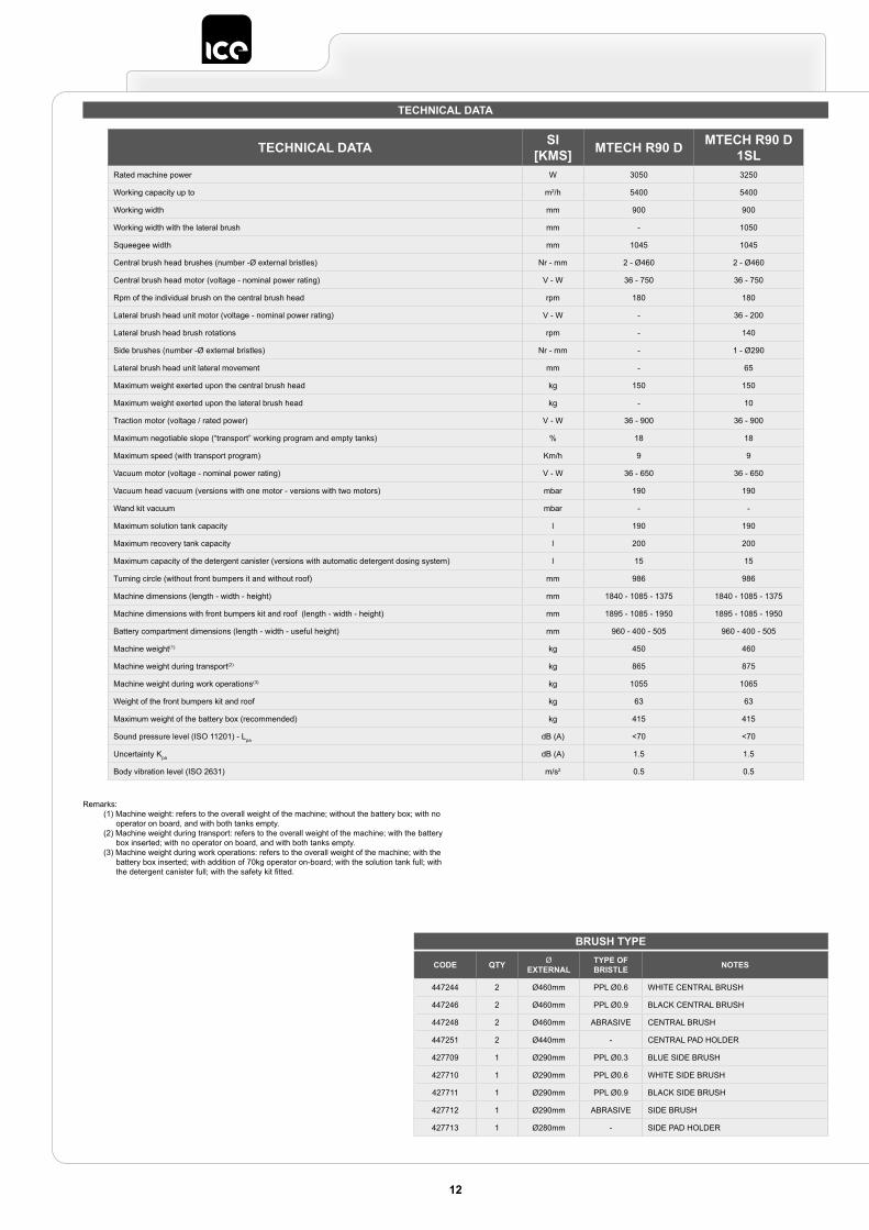
TECHNICAL DATA
Remarks:(1) Machine weight: refers to the overall weight of the machine; without the battery box; with no
operator on board, and with both tanks empty.(2) Machine weight during transport: refers to the overall weight of the machine; with the battery
box inserted; with no operator on board, and with both tanks empty.(3) Machine weight during work operations: refers to the overall weight of the machine; with the
battery box inserted; with addition of 70kg operator on-board; with the solution tank full; with the detergent canister full; with the safety kit fitted.
BRUSH TYPE
CODE QTY Ø EXTERNAL
TYPE OF BRISTLE NOTES
447244 2 Ø460mm PPL Ø0.6 WHITE CENTRAL BRUSH
447246 2 Ø460mm PPL Ø0.9 BLACK CENTRAL BRUSH
447248 2 Ø460mm ABRASIVE CENTRAL BRUSH
447251 2 Ø440mm - CENTRAL PAD HOLDER
427709 1 Ø290mm PPL Ø0.3 BLUE SIDE BRUSH
427710 1 Ø290mm PPL Ø0.6 WHITE SIDE BRUSH
427711 1 Ø290mm PPL Ø0.9 BLACK SIDE BRUSH
427712 1 Ø290mm ABRASIVE SIDE BRUSH
427713 1 Ø280mm - SIDE PAD HOLDER
12
TECHNICAL DATA SI[KMS] MTECH R90 D MTECH R90 D
1SLRated machine power W 3050 3250
Working capacity up to m2/h 5400 5400
Working width mm 900 900
Working width with the lateral brush mm - 1050
Squeegee width mm 1045 1045
Central brush head brushes (number -Ø external bristles) Nr - mm 2 - Ø460 2 - Ø460
Central brush head motor (voltage - nominal power rating) V - W 36 - 750 36 - 750
Rpm of the individual brush on the central brush head rpm 180 180
Lateral brush head unit motor (voltage - nominal power rating) V - W - 36 - 200
Lateral brush head brush rotations rpm - 140
Side brushes (number -Ø external bristles) Nr - mm - 1 - Ø290
Lateral brush head unit lateral movement mm - 65
Maximum weight exerted upon the central brush head kg 150 150
Maximum weight exerted upon the lateral brush head kg - 10
Traction motor (voltage / rated power) V - W 36 - 900 36 - 900
Maximum negotiable slope (“transport” working program and empty tanks) % 18 18
Maximum speed (with transport program) Km/h 9 9
Vacuum motor (voltage - nominal power rating) V - W 36 - 650 36 - 650
Vacuum head vacuum (versions with one motor - versions with two motors) mbar 190 190
Wand kit vacuum mbar - -
Maximum solution tank capacity l 190 190
Maximum recovery tank capacity l 200 200
Maximum capacity of the detergent canister (versions with automatic detergent dosing system) l 15 15
Turning circle (without front bumpers it and without roof) mm 986 986
Machine dimensions (length - width - height) mm 1840 - 1085 - 1375 1840 - 1085 - 1375
Machine dimensions with front bumpers kit and roof (length - width - height) mm 1895 - 1085 - 1950 1895 - 1085 - 1950
Battery compartment dimensions (length - width - useful height) mm 960 - 400 - 505 960 - 400 - 505
Machine weight(1) kg 450 460
Machine weight during transport(2) kg 865 875
Machine weight during work operations(3) kg 1055 1065
Weight of the front bumpers kit and roof kg 63 63
Maximum weight of the battery box (recommended) kg 415 415
Sound pressure level (ISO 11201) - Lpa dB (A) <70 <70
Uncertainty Kpa dB (A) 1.5 1.5
Body vibration level (ISO 2631) m/s2 0.5 0.5

Remarks:(1) Machine weight: refers to the overall weight of the machine; without the battery box; with no
operator on board, and with both tanks empty.(2) Machine weight during transport: refers to the overall weight of the machine; with the battery
box inserted; with no operator on board, and with both tanks empty.(3) Machine weight during work operations: refers to the overall weight of the machine; with the
battery box inserted; with addition of 70kg operator on-board; with the solution tank full; with the detergent canister full; with the safety kit fitted.
BRUSH TYPE
CODE QTY Ø EXTERNAL LENGTH TYPE OF
BRISTLE NOTES
447963 2 200mm 856mm PPL 0.6mm CENTRAL BRUSH
447964 2 200mm 856mm PPL 0.9mm CENTRAL BRUSH
447965 2 200mm 856mm ABRASIVE CENTRAL BRUSH
437874 2 450 - PPL 1mm SIDE BRUSH
13
TECHNICAL DATA SI[KMS] MTECH R90 C MTECH R90 C
2SLRated machine power W 3050 3230
Working capacity up to m2/h 5000 5000
Working width mm 825 1225
Working width with the lateral brush mm - 1050
Squeegee width mm 1045 1045
Central brush head brushes (number -Ø external bristles-length) Nr - (Ømm - mm) 2 - (Ø200 - 856) 2 - (Ø200 - 856)
Central brush head motor (voltage - nominal power rating) V - W 36 - 750 36 - 750
Rpm of the individual brush on the central brush head rpm 550 550
Lateral brush head unit motor (voltage - nominal power rating) V - W - 36 - 90
Lateral brush head brush rotations rpm - 75
Side brushes (number -Ø external bristles) Nr - mm - 2 - Ø450
Maximum weight exerted upon the central brush head kg 60 60
Maximum weight exerted upon the lateral brush head kg - 5
Traction motor (voltage / rated power) V - W 36 - 900 36 - 900
Maximum negotiable slope (“transport” working program and empty tanks) % 18 18
Maximum speed (with transport program) Km/h 9 9
Vacuum motor (voltage - nominal power rating) V - W 36 - 650 36 - 650
Vacuum head vacuum (versions with one motor - versions with two motors) mbar 190 190
Wand kit vacuum mbar - -
Maximum solution tank capacity l 190 190
Maximum recovery tank capacity l 200 200
Maximum capacity of the detergent canister (versions with automatic detergent dosing system) l 15 15
Debris hopper volume l 16 16
Turning circle (without front bumpers it and without roof) mm 986 986
Machine dimensions (length - width - height) mm 1840 - 1085 - 1375 1840 - 1085 - 1375
Machine dimensions with front bumpers kit and roof (length - width - height) mm 1895 - 1085 - 1950 1895 - 1085 - 1950
Battery compartment dimensions (length - width - useful height) mm 960 - 400 - 505 960 - 400 - 505
Machine weight(1) kg 440 445
Machine weight during transport(2) kg 855 860
Machine weight during work operations(3) kg 1045 1050
Weight of the front bumpers kit and roof kg 63 63
Maximum weight of the battery box (recommended) kg 415 415
Sound pressure level (ISO 11201) - Lpa dB (A) <70 <70
Uncertainty Kpa dB (A) 1.5 1.5
Body vibration level (ISO 2631) m/s2 0.5 0.5
SYMBOLS USED ON THE MACHINE
LABELS USED ON THE MACHINE
14
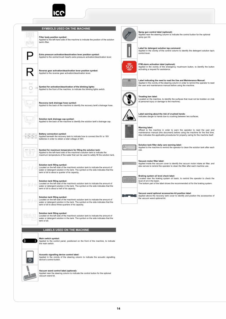
Filter body position symbol:Applied to the left-hand side of the machine to indicate the position of the solution tank's filter.
P Extra pressure activation/deactivation lever position symbol:Applied to the central brush head's extra pressure activation/deactivation lever.
R Reverse gear activation/deactivation lever position symbol:Applied to the reverse gear activation/deactivation lever.
Symbol for activation/deactivation of the blinking lights:Applied to the front of the machine, to indicate the blinking lights switch.
Recovery tank drainage hose symbol:Applied to the back of the machine to identify the recovery tank's drainage hose.
Solution tank drainage cap symbol:Applied to the back of the machine to identify the solution tank's drainage cap.
Battery connection symbol:Applied beneath the recovery tank to indicate how to connect the 6V or 18V batteries in order to obtain a total voltage of 36V.
Symbol for maximum temperature for filling the solution tank:Applied to the left-hand side of the machine's solution tank to indicate the maximum temperature of the water that can be used to safely fill the solution tank.
Solution tank filling symbol:Located on the left side of the machine's solution tank to indicate the amount of water or detergent solution in the tank. The symbol on the side indicates that the tank is full to about a quarter of its capacity.
Solution tank filling symbol:Located on the left side of the machine's solution tank to indicate the amount of water or detergent solution in the tank. The symbol on the side indicates that the tank is full to about a half of its capacity.
Solution tank filling symbol:Located on the left side of the machine's solution tank to indicate the amount of water or detergent solution in the tank. The symbol on the side indicates that the tank is full to about three-quarters of its capacity.
Solution tank filling symbol:Located on the left side of the machine's solution tank to indicate the amount of water or detergent solution in the tank. The symbol on the side indicates that the tank is full.
Main switch symbol:Applied to the control panel, positioned on the front of the machine, to indicate the main switch.
Acoustic signalling device control label:Applied in the vicinity of the steering column to indicate the acoustic signalling device's control button.
Vacuum wand control label (optional):Applied near the steering column to indicate the control button for the optional vacuum wand kit.
Spray gun control label (optional):Applied near the steering column to indicate the control button for the optional spray gun kit.
Label for detergent solution tap command:Applied in the vicinity of the control column to identify the detergent solution tap's control lever.
FFM alarm activation label (optional):Applied in the vicinity of the emergency mushroom button, to identify the button activating a request for assistance.
Label indicating the need to read the Use and Maintenance Manual:Applied in the vicinity of the steering column in order to remind the operator to read the user and maintenance manual before using the machine.
Treading ban label:Located on the machine, to identify the surfaces that must not be trodden on (risk of personal injury or damage to the machine).
Label warning about the risk of crushed hands:Indicates danger to hands due to crushing between two surfaces.
Warning label:Affixed to the machine in order to warn the operator to read the user and maintenance manual (this document) before using the machine for the first time. Also indicates the applicable procedures for properly caring for the machine itself.
Solution tank filter daily care warning label:Applied to the machine to remind the operator to clean the solution tank after each use.
Vacuum motor filter label:Applied inside the vacuum cover to identify the vacuum motor intake air filter, and also serves to remind the operator to clean the filter after each machine use.
Braking system oil level check label:Located near the braking system oil basin, to remind the operator to check the level of oil in the basin.The bottom part of the label shows the recommended oil for the braking system.
11 1 2
2
3
3
4
4
Vacuum wand optional accessories kit position label:Applied above the recovery tank cover to identify and position the accessories of the vacuum wand optional kit.
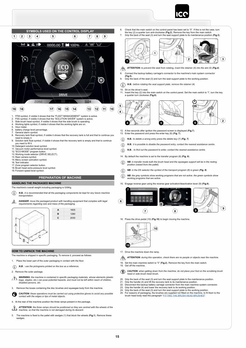
SYMBOLS USED ON THE CONTROL DISPLAY
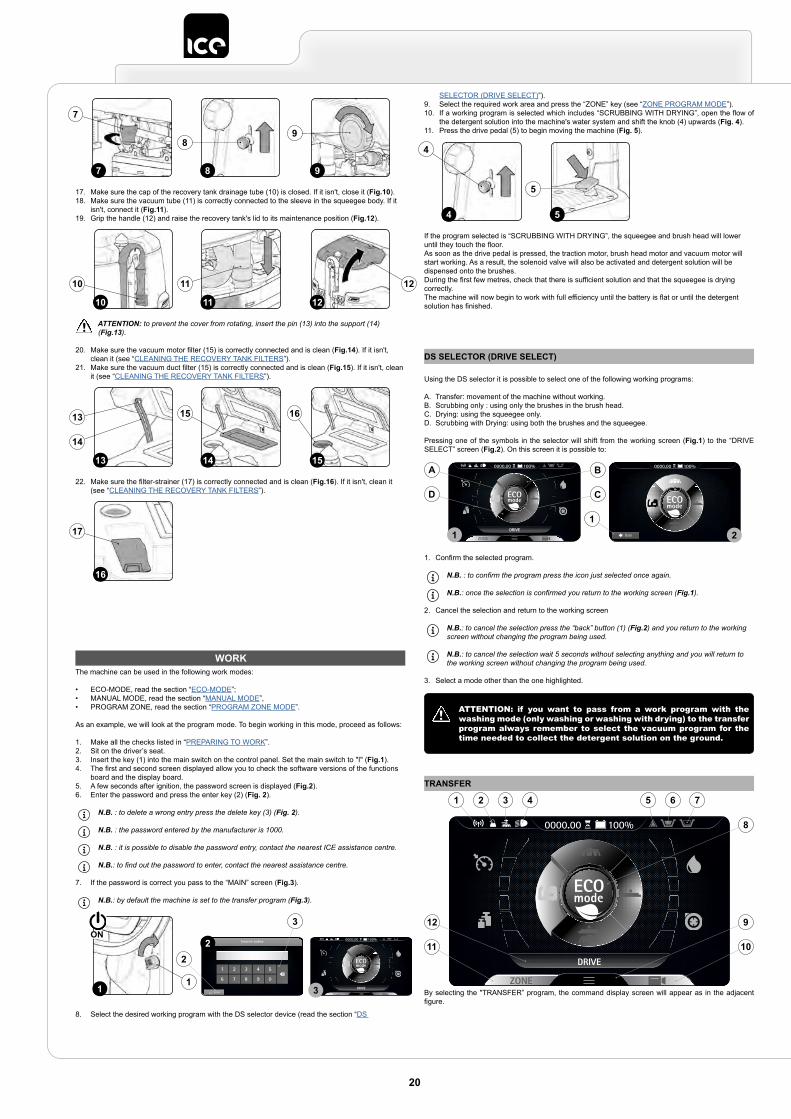
DRIVE
0000.00 100%
1 2 3 4 5 6 7
1719
8
1618
9
1012 111315 14
1. FFM symbol, if visible it shows that the “FLEET MANAGEMENT” system is active.2. FSS symbol, if visible it shows that the “SOLUTION SAVER” system is active.3. Side brush head symbol, if visible it shows that the side brush is operating.4. Working lights symbol, if visible it shows that the working lights are on.5. Hour meter.6. battery charge level percentage.7. General alarm symbol.8. Recovery tank float symbol, if visible it shows that the recovery tank is full and that to continue you
need to empty it.9. Solution tank float symbol, if visible it shows that the recovery tank is empty and that to continue
you need to fill it.10. Detergent solution level symbol.11. Vacuum motor performance level symbol.12. "ECO-MODE" program button.13. Working mode selector (DRIVE SELECT).14. Rear camera symbol.15. Menu screen activation symbol.16. Text indicator.17. Zone program selector button.18. Brush head extra pressure level symbol.19. Forward speed level symbol.
PREPARATION OF MACHINEHANDLING THE PACKAGED MACHINEThe machine's overall weight including packaging is 535Kg.
N.B.: it is recommended that all the packaging components be kept for any future machine transportation.
DANGER: move the packaged product with handling equipment that complies with legal requirements regarding size and mass of the packaging.
A 1605
B 1280
C 2030
HOW TO UNPACK THE MACHINEThe machine is shipped in specific packaging. To remove it, proceed as follows:
1. Place the lower part of the outer packaging in contact with the floor.
N.B. : use the pictograms printed on the box as a reference.
2. Remove the outer package.
WARNING: the machine is contained in specific packaging materials, whose elements (plastic bags, staples, etc.) can pose potential hazards, and must not be left within reach of children, disabled persons, etc.
3. Remove the boxes containing the disc brushes and squeegee body from the machine.
CAUTION: these operations must be carried out using protective gloves to avoid any possible contact with the edges or tips of metal objects.
4. At the rear of the machine position the three ramps present in the package.
ATTENTION: the three ramps should be positioned so they are centred with the wheels of the machine, so that the machine is not damaged during its descent.
5. The machine is fixed to the pallet with wedges (1) that block the wheels (Fig.1). Remove these wedges.
6. Check that the main switch on the control panel has been set to “0”. If this is not the case, turn the key (2) a quarter turn anti-clockwise (Fig.2). Remove the key from the main switch.
7. Grip the back of the seat (3) and turn the seat support plate to its maintenance position (Fig.3).
ATTENTION: to prevent the seat from rotating, insert the retainer (4) into the slot (5) (Fig.4).
8. Connect the backup battery carriage's connector to the machine's main system connector (Fig.5).
9. Grip the back of the seat (3) and turn the seat support plate to the working position.
N.B.: before rotating the seat support plate, remove the retainer (4).
10. Sit on the driver’s seat.11. Insert the key (2) into the main switch on the control panel. Set the main switch to “I”, turn the key
a quarter turn clockwise (Fig.6).
12. A few seconds after ignition the password screen is displayed (Fig.7).13. Enter the password and press the enter key (6) (Fig. 7).
N.B.: to delete a wrong entry press the delete key (7) (Fig. 7).
N.B.: it is possible to disable the password entry, contact the nearest assistance centre.
N.B. : to find out the password to enter, contact the nearest assistance centre.
14. By default the machine is set to the transfer program (8) (Fig. 8).
NB: in transfer mode both the brush head and the squeegee support will be in the resting position (raised from the pallet).
NB: in the DS selector the symbol of the transport program (8) is green (Fig. 8).
NB: the grey symbols show working programs that are not active. the green symbols show working programs that are active.
15. Engage reverse gear using the reverse gear activation/deactivation lever (9) (Fig.9).
16. Press the drive pedal (10) (Fig.10) to begin moving the machine.
17. Drive the machine down the ramp.
ATTENTION: during this operation, check there are no people or objects near the machine.
18. Set the main machine switch to “0” (Fig.2). Remove the key from the main switch.19. Get off the machine.
CAUTION: when getting down from the machine, do not place your foot on the scrubbing brush head or side brush head brush.
20. Grip the back of the seat (3) and turn the seat support plate to the maintenance position.21. Grip the handle (4) and lift the recovery tank to its maintenance position.22. Disconnect the backup battery carriage connector from the main machine system connector.23. Grip the handle (4) and lower the recovery tank to its working position.24. Grip the back of the seat (3) and turn the seat support plate to the working position.25. For reasons of packaging, the brushes are supplied not fitted on the machine, to fit them to the
brush head body read the paragraph “FITTING THE BRUSH HEAD BRUSHES”.
2 31
1
2 3
6 2
ON
4
4
5
5
Enter
Inserire codice
DRIVE
0000.00 100%7
8
7
6
8 9 9
10
10
15
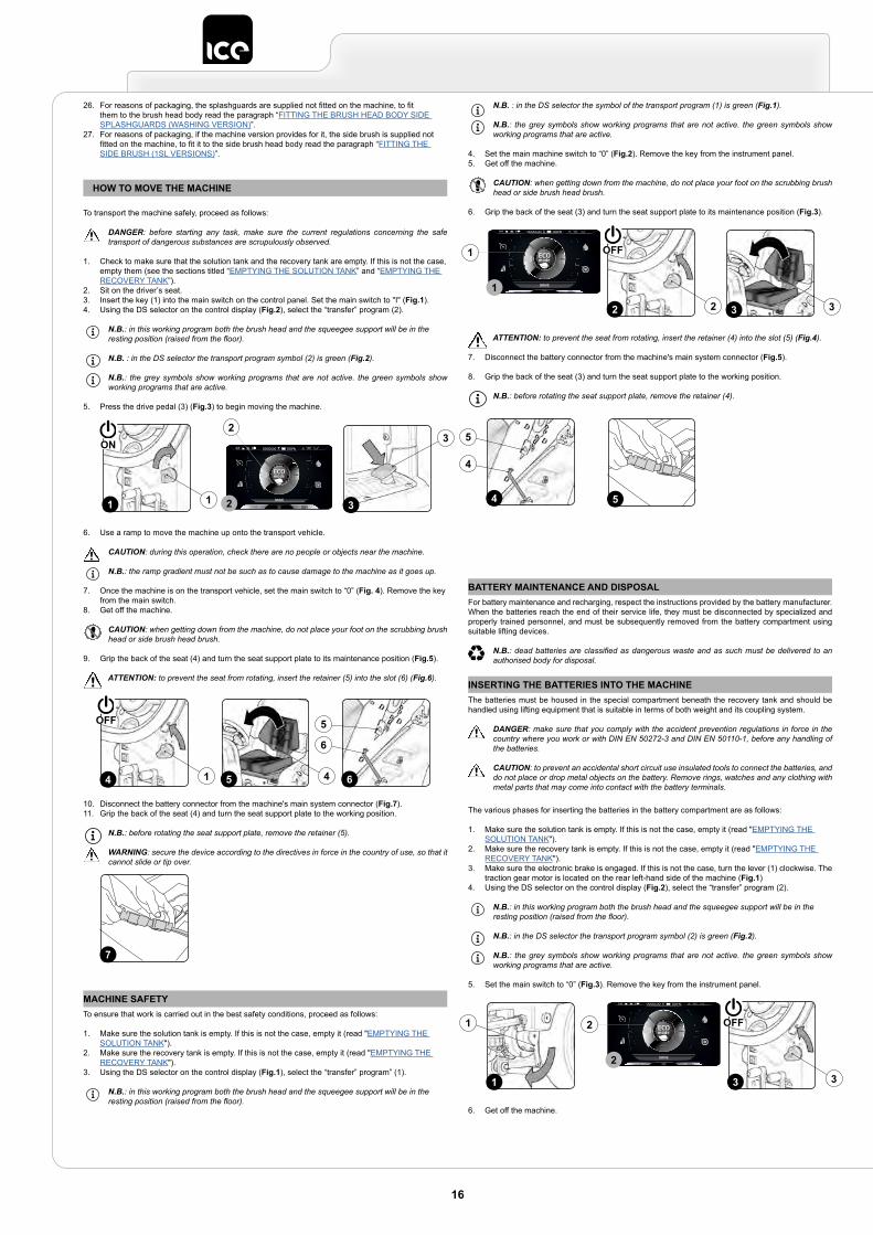
26. For reasons of packaging, the splashguards are supplied not fitted on the machine, to fit them to the brush head body read the paragraph “FITTING THE BRUSH HEAD BODY SIDE SPLASHGUARDS (WASHING VERSION)”.
27. For reasons of packaging, if the machine version provides for it, the side brush is supplied not fitted on the machine, to fit it to the side brush head body read the paragraph “FITTING THE SIDE BRUSH (1SL VERSIONS)”.
HOW TO MOVE THE MACHINE
To transport the machine safely, proceed as follows:
DANGER: before starting any task, make sure the current regulations concerning the safe transport of dangerous substances are scrupulously observed.
1. Check to make sure that the solution tank and the recovery tank are empty. If this is not the case, empty them (see the sections titled “EMPTYING THE SOLUTION TANK” and “EMPTYING THE RECOVERY TANK”).
2. Sit on the driver’s seat.3. Insert the key (1) into the main switch on the control panel. Set the main switch to "I" (Fig.1).4. Using the DS selector on the control display (Fig.2), select the “transfer” program (2).
N.B.: in this working program both the brush head and the squeegee support will be in the resting position (raised from the floor).
N.B. : in the DS selector the transport program symbol (2) is green (Fig.2).
N.B.: the grey symbols show working programs that are not active. the green symbols show working programs that are active.
5. Press the drive pedal (3) (Fig.3) to begin moving the machine.
6. Use a ramp to move the machine up onto the transport vehicle.
CAUTION: during this operation, check there are no people or objects near the machine.
N.B.: the ramp gradient must not be such as to cause damage to the machine as it goes up.
7. Once the machine is on the transport vehicle, set the main switch to “0” (Fig. 4). Remove the key from the main switch.
8. Get off the machine.
CAUTION: when getting down from the machine, do not place your foot on the scrubbing brush head or side brush head brush.
9. Grip the back of the seat (4) and turn the seat support plate to its maintenance position (Fig.5).
ATTENTION: to prevent the seat from rotating, insert the retainer (5) into the slot (6) (Fig.6).
10. Disconnect the battery connector from the machine's main system connector (Fig.7).11. Grip the back of the seat (4) and turn the seat support plate to the working position.
N.B.: before rotating the seat support plate, remove the retainer (5).
WARNING: secure the device according to the directives in force in the country of use, so that it cannot slide or tip over.
1 1
ON
3
3
DRIVE
0000.00 100%
2
2
5 64
6
5
4 1
OFF
7
MACHINE SAFETYTo ensure that work is carried out in the best safety conditions, proceed as follows:
1. Make sure the solution tank is empty. If this is not the case, empty it (read "EMPTYING THE SOLUTION TANK").
2. Make sure the recovery tank is empty. If this is not the case, empty it (read "EMPTYING THE RECOVERY TANK").
3. Using the DS selector on the control display (Fig.1), select the “transfer” program” (1).
N.B.: in this working program both the brush head and the squeegee support will be in the resting position (raised from the floor).
N.B. : in the DS selector the symbol of the transport program (1) is green (Fig.1).
N.B.: the grey symbols show working programs that are not active. the green symbols show working programs that are active.
4. Set the main machine switch to “0” (Fig.2). Remove the key from the instrument panel.5. Get off the machine.
CAUTION: when getting down from the machine, do not place your foot on the scrubbing brush head or side brush head brush.
6. Grip the back of the seat (3) and turn the seat support plate to its maintenance position (Fig.3).
ATTENTION: to prevent the seat from rotating, insert the retainer (4) into the slot (5) (Fig.4).
7. Disconnect the battery connector from the machine's main system connector (Fig.5).
8. Grip the back of the seat (3) and turn the seat support plate to the working position.
N.B.: before rotating the seat support plate, remove the retainer (4).
3 32 2
OFF
DRIVE
0000.00 100%
1
1
4
4
5
5
BATTERY MAINTENANCE AND DISPOSALFor battery maintenance and recharging, respect the instructions provided by the battery manufacturer.When the batteries reach the end of their service life, they must be disconnected by specialized and properly trained personnel, and must be subsequently removed from the battery compartment using suitable lifting devices.
N.B.: dead batteries are classified as dangerous waste and as such must be delivered to an authorised body for disposal.
INSERTING THE BATTERIES INTO THE MACHINEThe batteries must be housed in the special compartment beneath the recovery tank and should be handled using lifting equipment that is suitable in terms of both weight and its coupling system.
DANGER: make sure that you comply with the accident prevention regulations in force in the country where you work or with DIN EN 50272-3 and DIN EN 50110-1, before any handling of the batteries.
CAUTION: to prevent an accidental short circuit use insulated tools to connect the batteries, and do not place or drop metal objects on the battery. Remove rings, watches and any clothing with metal parts that may come into contact with the battery terminals.
The various phases for inserting the batteries in the battery compartment are as follows:
1. Make sure the solution tank is empty. If this is not the case, empty it (read "EMPTYING THE SOLUTION TANK").
2. Make sure the recovery tank is empty. If this is not the case, empty it (read "EMPTYING THE RECOVERY TANK").
3. Make sure the electronic brake is engaged. If this is not the case, turn the lever (1) clockwise. The traction gear motor is located on the rear left-hand side of the machine (Fig.1)
4. Using the DS selector on the control display (Fig.2), select the “transfer” program (2).
N.B.: in this working program both the brush head and the squeegee support will be in the resting position (raised from the floor).
N.B.: in the DS selector the transport program symbol (2) is green (Fig.2).
N.B.: the grey symbols show working programs that are not active. the green symbols show working programs that are active.
5. Set the main switch to “0” (Fig.3). Remove the key from the instrument panel.
6. Get off the machine.
3 3
OFF
DRIVE
0000.00 100%
2
2
1
1
16
CAUTION: when getting down from the machine, do not place your foot on the scrubbing brush head or side brush head brush.
7. Grip the back of the seat (4) and turn the seat support plate to its maintenance position (Fig.4).
ATTENTION: to prevent the seat from rotating, insert the retainer (5) into the slot (6) (Fig.5).
8. Disconnect the battery connector from the machine's main system connector (Fig.6).
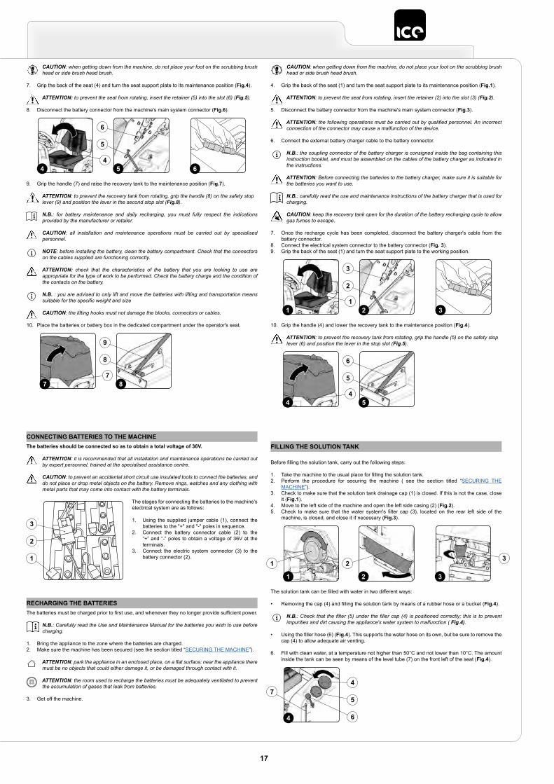
9. Grip the handle (7) and raise the recovery tank to the maintenance position (Fig.7).
ATTENTION: to prevent the recovery tank from rotating, grip the handle (8) on the safety stop lever (9) and position the lever in the second stop slot (Fig.8).
N.B.: for battery maintenance and daily recharging, you must fully respect the indications provided by the manufacturer or retailer.
CAUTION: all installation and maintenance operations must be carried out by specialised personnel.
NOTE: before installing the battery, clean the battery compartment. Check that the connectors on the cables supplied are functioning correctly.
ATTENTION: check that the characteristics of the battery that you are looking to use are appropriate for the type of work to be performed. Check the battery charge and the condition of the contacts on the battery.
N.B. : you are advised to only lift and move the batteries with lifting and transportation means suitable for the specific weight and size
CAUTION: the lifting hooks must not damage the blocks, connectors or cables.
10. Place the batteries or battery box in the dedicated compartment under the operator's seat.
4 5 64
6
5
7 87
9
8
CONNECTING BATTERIES TO THE MACHINEThe batteries should be connected so as to obtain a total voltage of 36V.
ATTENTION: it is recommended that all installation and maintenance operations be carried out by expert personnel, trained at the specialised assistance centre.
CAUTION: to prevent an accidental short circuit use insulated tools to connect the batteries, and do not place or drop metal objects on the battery. Remove rings, watches and any clothing with metal parts that may come into contact with the battery terminals.
The stages for connecting the batteries to the machine's electrical system are as follows:
1. Using the supplied jumper cable (1), connect the batteries to the "+" and "-" poles in sequence.
2. Connect the battery connector cable (2) to the “+” and “-“ poles to obtain a voltage of 36V at the terminals.
3. Connect the electric system connector (3) to the battery connector (2).
3
2
1
RECHARGING THE BATTERIESThe batteries must be charged prior to first use, and whenever they no longer provide sufficient power.
N.B.: Carefully read the Use and Maintenance Manual for the batteries you wish to use before charging.
1. Bring the appliance to the zone where the batteries are charged.2. Make sure the machine has been secured (see the section titled “SECURING THE MACHINE”).
ATTENTION: park the appliance in an enclosed place, on a flat surface; near the appliance there must be no objects that could either damage it, or be damaged through contact with it.
ATTENTION: the room used to recharge the batteries must be adequately ventilated to prevent the accumulation of gases that leak from batteries.
3. Get off the machine.
CAUTION: when getting down from the machine, do not place your foot on the scrubbing brush head or side brush head brush.
4. Grip the back of the seat (1) and turn the seat support plate to its maintenance position (Fig.1).
ATTENTION: to prevent the seat from rotating, insert the retainer (2) into the slot (3) (Fig.2).
5. Disconnect the battery connector from the machine's main system connector (Fig.3).
ATTENTION: the following operations must be carried out by qualified personnel. An incorrect connection of the connector may cause a malfunction of the device.
6. Connect the external battery charger cable to the battery connector.
N.B.: the coupling connector of the battery charger is consigned inside the bag containing this instruction booklet, and must be assembled on the cables of the battery charger as indicated in the instructions.
ATTENTION: Before connecting the batteries to the battery charger, make sure it is suitable for the batteries you want to use.
N.B.: carefully read the use and maintenance instructions of the battery charger that is used for charging.
CAUTION: keep the recovery tank open for the duration of the battery recharging cycle to allow gas fumes to escape.
7. Once the recharge cycle has been completed, disconnect the battery charger's cable from the battery connector.
8. Connect the electrical system connector to the battery connector (Fig. 3).9. Grip the back of the seat (1) and turn the seat support plate to the working position.
10. Grip the handle (4) and lower the recovery tank to the maintenance position (Fig.4).
ATTENTION: to prevent the recovery tank from rotating, grip the handle (5) on the safety stop lever (6) and position the lever in the stop slot (Fig.5).
1 2 31
3
2
4 54
6
5
FILLING THE SOLUTION TANK
Before filling the solution tank, carry out the following steps:
1. Take the machine to the usual place for filling the solution tank.2. Perform the procedure for securing the machine ( see the section titled “SECURING THE
MACHINE”).3. Check to make sure that the solution tank drainage cap (1) is closed. If this is not the case, close
it (Fig.1).4. Move to the left side of the machine and open the left side casing (2) (Fig.2).5. Check to make sure that the water system's filter cap (3), located on the rear left side of the
machine, is closed, and close it if necessary (Fig.3).
The solution tank can be filled with water in two different ways:
• Removing the cap (4) and filling the solution tank by means of a rubber hose or a bucket (Fig.4).
N.B.: Check that the filter (5) under the filler cap (4) is positioned correctly; this is to prevent impurities and dirt causing the appliance's water system to malfunction ( Fig.4).
• Using the filler hose (6) (Fig.4). This supports the water hose on its own, but be sure to remove the cap (4) to allow adequate air venting.
6. Fill with clean water, at a temperature not higher than 50°C and not lower than 10°C. The amount inside the tank can be seen by means of the level tube (7) on the front left of the seat (Fig.4).
2 31
1 23
4
75
6
4
17

DETERGENT SOLUTIONFor the versions without automatic detergent dosing system, after filling the solution tank with clean water, add the liquid detergent to the tank in the concentration and manner indicated on the detergent manufacturer's label. To prevent the formation of an excessive amount of foam that could damage the vacuum motor, use the minimum percentage of detergent required.
CAUTION: protective gloves should always be worn before handling detergents or acidic or alkaline solutions, to avoid serious injury to the hands.
ATTENTION: always use detergents whose manufacturer's label indicates their suitability for scrubbing machines. Do not use acid or alkaline products or solvents without this indication.
ATTENTION: always use low-foam detergent. To avoid the production of foam, put a minimum quantity of anti-foam liquid in the recovery tank before starting to clean. Do not use pure acids.
For versions with automatic detergent dosing system, fill the solution tank with clean water and then proceed as follows:
1. Make sure the machine is in a safe condition (read “MACHINE SAFETY”).
CAUTION: protective gloves should always be worn before handling detergents or acidic or alkaline solutions, to avoid serious injury to the hands.
2. Remove the cap (1) of the detergent canister (Fig.1).3. Fill the canister with the desired detergent; it is possible to see the quantity ion the detergent
canister using the level tube (2) on the front left of the canister (Fig. 1).
ATTENTION: always use detergents whose manufacturer's label indicates their suitability for scrubbing machines. Do
not use acid or alkaline products or solvents without this indication.
ATTENTION: the dosing system is suitable for frequent maintenance cleaning. Acid or alkaline maintenance detergent tank be used with pH values between 4 and 10
and that do not contain: oxidising agents, chlorine or bromine, formaldehyde, mineral solvents. The detergents used must be suitable for use with scrubbing machines. Wash the circuit with water after use
if the system is not used daily. The system can be excluded. In case of sporadic use of detergents with pH between 1-3 or 11-14, use the floor scrubbing machine in the traditional way by adding the detergent in the clean water tank and excluding the dosing circuit.
ATTENTION: always use low-foam detergent. To avoid the production of foam, put a minimum quantity of anti-foam liquid in the recovery tank before starting to clean. Do not use pure acids.
4. Close the cap (1) correctly to prevent liquid coming out when working.
1
2
1
ADJUSTMENT OF DRIVING POSITIONThe proper adjustment of the driving position provides a greater sense of comfort when using the machine.
Correct position on the seat: make sure you sit upright and that your back and that your lower back and spine are at 90°.
Seat adjustment: The seat should always be positioned using the pedals as a reference. To adjust the seat use the lever (1) under it (Fig.1).
N.B.: The distance should be adjusted so that with the pedals fully pressed to the floor the knees are slightly bent
(about 120°).
N.B.: Adjust the distance of the seat so that when pressing the brake pedal it goes as far as it can. This operation
should be done with the machine running so as to pressurise the braking system.
N.B.: If the knee is not bent enough, it is too far from the steering wheel, if however the knee is bent almost 90°then it is too close to the steering wheel.
N.B.: The feet should be positioned keeping the heels on the footrest, the sole of the foot directly below the fingers should push the pedals.
N.B.: The ideal position is that which allows you to grip the steering wheel correctly with the palms slightly lower than the shoulders. With a good grip on the steering wheel, the elbows should be bent by about 120°. They should be at least 30 cm between the middle of the steering wheel and our breastbone. In any case, this distance should be no more than 45 cm.
Adjusting the armrests (optional): the armrests should be inclined to make using the machine comfortable.
N.B.: To adjust the armrest use the runner (2) under it (Fig.2).
N.B.: Taking the right armrest as a reference, if the wheel is turned outwards the inclination of the armrest is increased.
Taking the left armrest as a reference, if the wheel is turned inwards the inclination of the armrest is increased.
Wear the seatbelt correctly (optional): The machine has a sub-abdominal safety device that allows the operator to be anchored to the driver's seat. To secure the safety belt, first of all you need to be sitting in the drier's seat, take the mobile part (3) of the belt, wrap it round the abdomen and insert the mobile part (3) in the slit in the fixed part (4) (Fig.3).
1
1
1
2
N.B.: Adjust the horizontal part of the belt so it is as tight as possible on the pelvis. The belt should be pulled and
put as low as possible on the pelvis bone, and not on the belly.
1
3
4
INSERTING WATER SYSTEM FILTERBefore using the machine for the first time the water system filter needs to be reset, for shipping reasons the filter cartridge and the cap have been removed. To insert the filter cartridge in the water system filter body proceed as follows:
1. Take the machine to the maintenance area.2. Make sure the machine has been secured (see the section titled “SECURING THE MACHINE”).
CAUTION: users are advised to always wear protective gloves, to avoid the risk of serious injury to hands.
3. Close the tap's output flow, and shift the knob (1) on the left hand side of the steering column (Fig.1) downward.
4. Open the machine's left lateral hatch (2) (Fig.2).5. Insert the filter cartridge (3) in the housing on the cap (4) (Fig.3).
N.B.: The O-ring gasket in the filter cartridge should be inserted into its seat in the cap.
6. Screw on the cap (4) to the body of the detergent solution filter (5) (Fig.4).
N.B.: For the sweeping versions, the water system filter is located on the right of the machine.
2 31
1
23
4
4
5
4
ASSEMBLING THE BRUSH HEAD BRUSHES (SCRUBBING VERSION)To fit the brush on the brush head body, proceed as follows:
1. Take the machine to the maintenance area.2. Make sure the machine has been secured (see the section titled “SECURING THE MACHINE”).
CAUTION: these operations must be carried out using protective gloves to avoid any possible contact with the edges or tips of metal objects.
3. Open the machine's left lateral carter (1) (Fig.1).4. Remove the left-hand splashguard (2) and move the fixing anchors (3) on the brush head body into
the maintenance position (Fig.2).5. With the brush head UP, insert the brush in the plate housing underneath the brush head, turning
it until the three buttons engage with the niches on the plate itself.6. Turn in increments until the button is pushed towards the coupling spring and is locked in place
(Fig.3).
N.B. : The image in Fig.3 indicates the direction of rotation for coupling the left brush; the right brush must be turned in the opposite direction.
31 2
1
2
3
FITTING LATERAL BRUSH 1SL (SCRUBBING )To fit the side brush on the brush head body, proceed as follows:
1. Make sure the machine has been secured (see the section titled “SECURING THE MACHINE”).
CAUTION: these operations must be carried out using protective gloves to avoid any possible contact with the edges or tips of metal objects.
2. With the brush head in its resting position, insert the brush into the plate housing underneath the brush head, and turn it until the two buttons engage with the niches on the plate itself (Fig.1).
3. Push the brush until the stopper spring on the brush itself has engaged with the niche present on the gear motor’s pin.
1
1
18
ASSEMBLING THE BRUSH HEAD BRUSHES (SWEEPING VERSION)To fit the brush on the brush head body, proceed as follows:
1. Make sure the machine has been secured (see the section titled “SECURING THE MACHINE”).
CAUTION: these operations must be carried out using protective gloves to avoid any possible contact with the edges or tips of metal objects.
2. Open the machine's left lateral carter (1) (Fig.1).3. With the brush head in its resting position, turn the knobs (2) that hold the left lateral carter (3) in
place anti-clockwise (Fig.2).4. Remove the left lateral carter (4) (Fig.3).
5. Insert the brush into the tunnel (Fig.4), taking care to make sure that the gear motor’s drive shaft enters the slit in the brush itself.
6. Repeat the previously described operations for the right-hand side as well.
N.B. : In order to be installed correctly, the brushes must form an X when viewed from above in the forward direction of movement (Fig.5).
1
1
2
2
33
4
5
4
ASSEMBLING SIDE BRUSH 2SL (SWEEPING VERSION)To fit the brush on the brush head body, proceed as follows:
1. Make sure the machine has been secured (see the section titled “SECURING THE MACHINE”).
CAUTION: these operations must be carried out using protective gloves to avoid any possible contact with the edges or tips of metal objects.
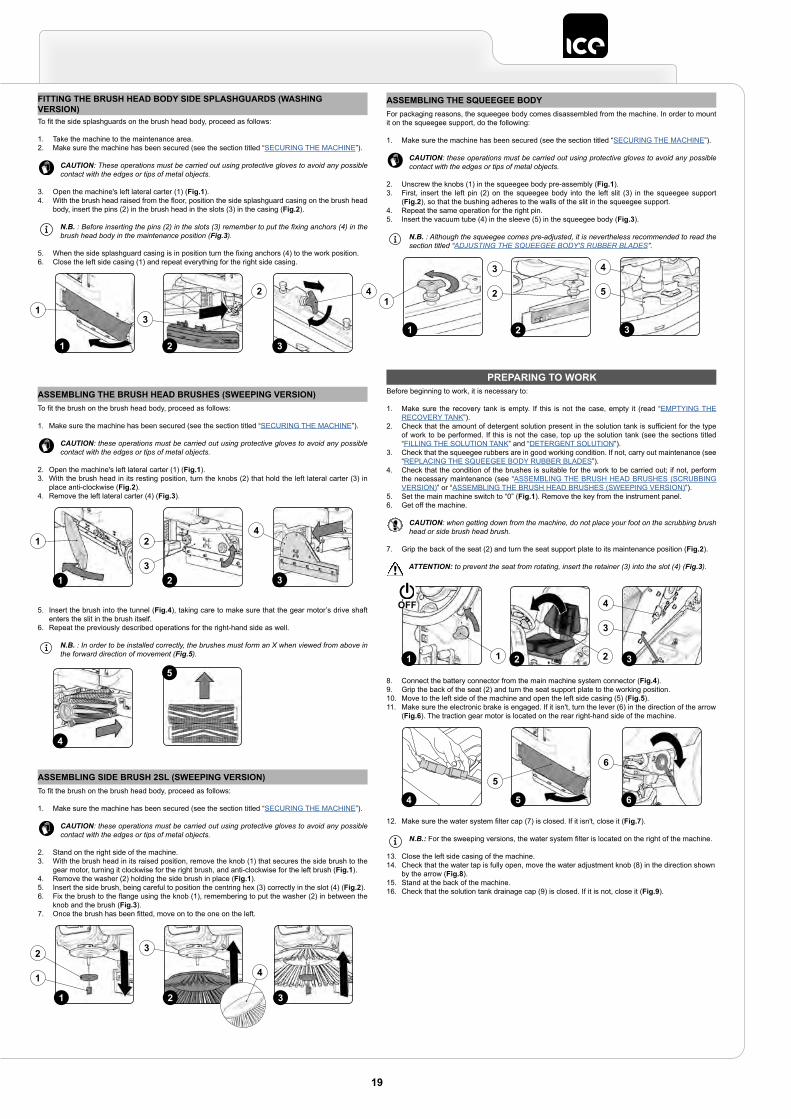
2. Stand on the right side of the machine.3. With the brush head in its raised position, remove the knob (1) that secures the side brush to the
gear motor, turning it clockwise for the right brush, and anti-clockwise for the left brush (Fig.1).4. Remove the washer (2) holding the side brush in place (Fig.1).5. Insert the side brush, being careful to position the centring hex (3) correctly in the slot (4) (Fig.2).6. Fix the brush to the flange using the knob (1), remembering to put the washer (2) in between the
knob and the brush (Fig.3).7. Once the brush has been fitted, move on to the one on the left.
1 32
2
1
3
4
ASSEMBLING THE SQUEEGEE BODYFor packaging reasons, the squeegee body comes disassembled from the machine. In order to mount it on the squeegee support, do the following:
1. Make sure the machine has been secured (see the section titled “SECURING THE MACHINE”).
CAUTION: these operations must be carried out using protective gloves to avoid any possible contact with the edges or tips of metal objects.
2. Unscrew the knobs (1) in the squeegee body pre-assembly (Fig.1).3. First, insert the left pin (2) on the squeegee body into the left slit (3) in the squeegee support
(Fig.2), so that the bushing adheres to the walls of the slit in the squeegee support.4. Repeat the same operation for the right pin.5. Insert the vacuum tube (4) in the sleeve (5) in the squeegee body (Fig.3).
N.B. : Although the squeegee comes pre-adjusted, it is nevertheless recommended to read the section titled “ADJUSTING THE SQUEEGEE BODY'S RUBBER BLADES”.
1 2 3
5
4
1
3
2
PREPARING TO WORKBefore beginning to work, it is necessary to:
1. Make sure the recovery tank is empty. If this is not the case, empty it (read “EMPTYING THE RECOVERY TANK”).
2. Check that the amount of detergent solution present in the solution tank is sufficient for the type of work to be performed. If this is not the case, top up the solution tank (see the sections titled “FILLING THE SOLUTION TANK” and “DETERGENT SOLUTION”).
3. Check that the squeegee rubbers are in good working condition. If not, carry out maintenance (see “REPLACING THE SQUEEGEE BODY RUBBER BLADES”).
4. Check that the condition of the brushes is suitable for the work to be carried out; if not, perform the necessary maintenance (see “ASSEMBLING THE BRUSH HEAD BRUSHES (SCRUBBING VERSION)” or “ASSEMBLING THE BRUSH HEAD BRUSHES (SWEEPING VERSION)”).
5. Set the main machine switch to “0” (Fig.1). Remove the key from the instrument panel.6. Get off the machine.
CAUTION: when getting down from the machine, do not place your foot on the scrubbing brush head or side brush head brush.
7. Grip the back of the seat (2) and turn the seat support plate to its maintenance position (Fig.2).
ATTENTION: to prevent the seat from rotating, insert the retainer (3) into the slot (4) (Fig.3).
8. Connect the battery connector from the main machine system connector (Fig.4).9. Grip the back of the seat (2) and turn the seat support plate to the working position.10. Move to the left side of the machine and open the left side casing (5) (Fig.5).11. Make sure the electronic brake is engaged. If it isn't, turn the lever (6) in the direction of the arrow
(Fig.6). The traction gear motor is located on the rear right-hand side of the machine.
12. Make sure the water system filter cap (7) is closed. If it isn't, close it (Fig.7).
N.B.: For the sweeping versions, the water system filter is located on the right of the machine.
13. Close the left side casing of the machine.14. Check that the water tap is fully open, move the water adjustment knob (8) in the direction shown
by the arrow (Fig.8).15. Stand at the back of the machine.16. Check that the solution tank drainage cap (9) is closed. If it is not, close it (Fig.9).
3
3
4
2 21 1
OFF
5 64
5
6
FITTING THE BRUSH HEAD BODY SIDE SPLASHGUARDS (WASHING VERSION)To fit the side splashguards on the brush head body, proceed as follows:
1. Take the machine to the maintenance area.2. Make sure the machine has been secured (see the section titled “SECURING THE MACHINE”).
CAUTION: These operations must be carried out using protective gloves to avoid any possible contact with the edges or tips of metal objects.
3. Open the machine's left lateral carter (1) (Fig.1).4. With the brush head raised from the floor, position the side splashguard casing on the brush head
body, insert the pins (2) in the brush head in the slots (3) in the casing (Fig.2).
N.B. : Before inserting the pins (2) in the slots (3) remember to put the fixing anchors (4) in the brush head body in the maintenance position (Fig.3).
5. When the side splashguard casing is in position turn the fixing anchors (4) to the work position.6. Close the left side casing (1) and repeat everything for the right side casing.
31 2
1
2 4
3
19
WORKThe machine can be used in the following work modes:
• ECO-MODE, read the section “ECO-MODE”;• MANUAL MODE, read the section “MANUAL MODE”,• PROGRAM ZONE, read the section “PROGRAM ZONE MODE”.
As an example, we will look at the program mode. To begin working in this mode, proceed as follows:
1. Make all the checks listed in “PREPARING TO WORK”.2. Sit on the driver’s seat.3. Insert the key (1) into the main switch on the control panel. Set the main switch to "I" (Fig.1).4. The first and second screen displayed allow you to check the software versions of the functions
board and the display board.5. A few seconds after ignition, the password screen is displayed (Fig.2).6. Enter the password and press the enter key (2) (Fig. 2).
N.B. : to delete a wrong entry press the delete key (3) (Fig. 2).
N.B. : the password entered by the manufacturer is 1000.
N.B. : it is possible to disable the password entry, contact the nearest ICE assistance centre.
N.B.: to find out the password to enter, contact the nearest assistance centre.
7. If the password is correct you pass to the “MAIN” screen (Fig.3).
N.B.: by default the machine is set to the transfer program (Fig.3).
8. Select the desired working program with the DS selector device (read the section “DS
1 Enter
Inserire codice
DRIVE
0000.00 100%2
31
3
2
ON
17. Make sure the cap of the recovery tank drainage tube (10) is closed. If it isn't, close it (Fig.10).18. Make sure the vacuum tube (11) is correctly connected to the sleeve in the squeegee body. If it
isn't, connect it (Fig.11).19. Grip the handle (12) and raise the recovery tank's lid to its maintenance position (Fig.12).
ATTENTION: to prevent the cover from rotating, insert the pin (13) into the support (14) (Fig.13).
20. Make sure the vacuum motor filter (15) is correctly connected and is clean (Fig.14). If it isn't, clean it (see “CLEANING THE RECOVERY TANK FILTERS”).
21. Make sure the vacuum duct filter (15) is correctly connected and is clean (Fig.15). If it isn't, clean it (see “CLEANING THE RECOVERY TANK FILTERS”).
22. Make sure the filter-strainer (17) is correctly connected and is clean (Fig.16). If it isn't, clean it (see “CLEANING THE RECOVERY TANK FILTERS”).
8 97
8
7
9
11 1210
10 11 12
14 1513
14
13 15 16
16
17
SELECTOR (DRIVE SELECT)”).9. Select the required work area and press the “ZONE” key (see “ZONE PROGRAM MODE”).10. If a working program is selected which includes “SCRUBBING WITH DRYING”, open the flow of
the detergent solution into the machine's water system and shift the knob (4) upwards (Fig. 4).11. Press the drive pedal (5) to begin moving the machine (Fig. 5).
If the program selected is “SCRUBBING WITH DRYING”, the squeegee and brush head will lower until they touch the floor.As soon as the drive pedal is pressed, the traction motor, brush head motor and vacuum motor will start working. As a result, the solenoid valve will also be activated and detergent solution will be dispensed onto the brushes.During the first few metres, check that there is sufficient solution and that the squeegee is drying correctly.The machine will now begin to work with full efficiency until the battery is flat or until the detergent solution has finished.
54
4
5
DS SELECTOR (DRIVE SELECT)
Using the DS selector it is possible to select one of the following working programs:
A. Transfer: movement of the machine without working.B. Scrubbing only : using only the brushes in the brush head.C. Drying: using the squeegee only.D. Scrubbing with Drying: using both the brushes and the squeegee.
Pressing one of the symbols in the selector will shift from the working screen (Fig.1) to the “DRIVE SELECT” screen (Fig.2). On this screen it is possible to:
DRIVE
0000.00 100%
Back
0000.00 100%A B
D C
11 2
1. Confirm the selected program.
N.B. : to confirm the program press the icon just selected once again.
N.B.: once the selection is confirmed you return to the working screen (Fig.1).
2. Cancel the selection and return to the working screen
N.B.: to cancel the selection press the “back” button (1) (Fig.2) and you return to the working screen without changing the program being used.
N.B.: to cancel the selection wait 5 seconds without selecting anything and you will return to the working screen without changing the program being used.
3. Select a mode other than the one highlighted.
ATTENTION: if you want to pass from a work program with the washing mode (only washing or washing with drying) to the transfer program always remember to select the vacuum program for the time needed to collect the detergent solution on the ground.
TRANSFER
DRIVE
0000.00 100%
912
8
1011
1 52 63 74
By selecting the "TRANSFER” program, the command display screen will appear as in the adjacent figure.
20
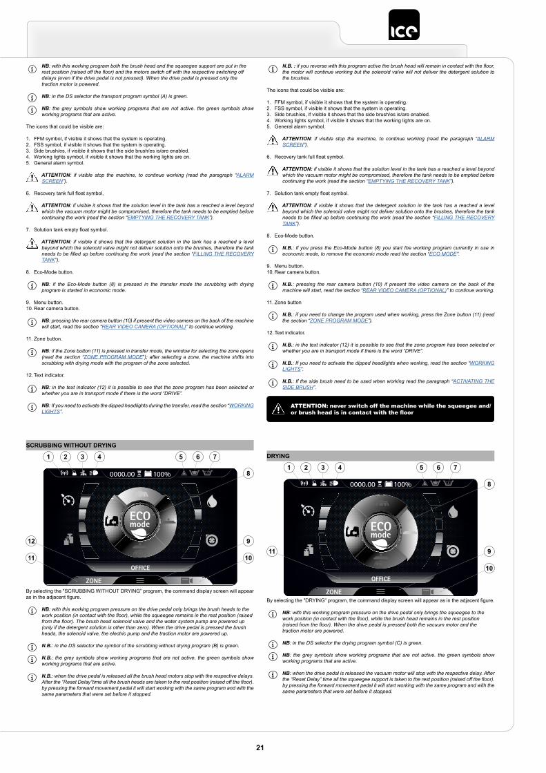
NB: with this working program both the brush head and the squeegee support are put in the rest position (raised off the floor) and the motors switch off with the respective switching off delays (even if the drive pedal is not pressed). When the drive pedal is pressed only the traction motor is powered.
NB: in the DS selector the transport program symbol (A) is green.
NB: the grey symbols show working programs that are not active. the green symbols show working programs that are active.
The icons that could be visible are:
1. FFM symbol, if visible it shows that the system is operating.2. FSS symbol, if visible it shows that the system is operating.3. Side brush/es, if visible it shows that the side brush/es is/are enabled.4. Working lights symbol, if visible it shows that the working lights are on.5. General alarm symbol.
ATTENTION: if visible stop the machine, to continue working (read the paragraph “ALARM SCREEN”).
6. Recovery tank full float symbol,
ATTENTION: if visible it shows that the solution level in the tank has a reached a level beyond which the vacuum motor might be compromised, therefore the tank needs to be emptied before continuing the work (read the section “EMPTYING THE RECOVERY TANK”).
7. Solution tank empty float symbol.
ATTENTION: if visible it shows that the detergent solution in the tank has a reached a level beyond which the solenoid valve might not deliver solution onto the brushes, therefore the tank needs to be filled up before continuing the work (read the section “FILLING THE RECOVERY TANK”).
8. Eco-Mode button.
NB: if the Eco-Mode button (8) is pressed in the transfer mode the scrubbing with drying program is started in economic mode.
9. Menu button.10. Rear camera button.
NB: pressing the rear camera button (10) if present the video camera on the back of the machine will start, read the section “REAR VIDEO CAMERA (OPTIONAL)” to continue working.
11. Zone button.
NB: if the Zone button (11) is pressed in transfer mode, the window for selecting the zone opens (read the section “ZONE PROGRAM MODE”); after selecting a zone, the machine shifts into scrubbing with drying mode with the program of the zone selected.
12. Text indicator.
NB: in the text indicator (12) it is possible to see that the zone program has been selected or whether you are in transport mode if there is the word “DRIVE”.
NB: If you need to activate the dipped headlights during the transfer, read the section “WORKING LIGHTS”.
SCRUBBING WITHOUT DRYING
OFFICE
0000.00 100%
9
8
1011
12
1 52 63 74
By selecting the "SCRUBBING WITHOUT DRYING” program, the command display screen will appear as in the adjacent figure.
NB: with this working program pressure on the drive pedal only brings the brush heads to the work position (in contact with the floor), while the squeegee remains in the rest position (raised from the floor). The brush head solenoid valve and the water system pump are powered up (only if the detergent solution is other than zero). When the drive pedal is pressed the brush heads, the solenoid valve, the electric pump and the traction motor are powered up.
N.B.: in the DS selector the symbol of the scrubbing without drying program (B) is green.
N.B.: the grey symbols show working programs that are not active. the green symbols show working programs that are active.
N.B.: when the drive pedal is released all the brush head motors stop with the respective delays. After the “Reset Delay”time all the brush heads are taken to the rest position (raised off the floor). by pressing the forward movement pedal it will start working with the same program and with the same parameters that were set before it stopped.
N.B. : if you reverse with this program active the brush head will remain in contact with the floor, the motor will continue working but the solenoid valve will not deliver the detergent solution to the brushes.
The icons that could be visible are:
1. FFM symbol, if visible it shows that the system is operating.2. FSS symbol, if visible it shows that the system is operating.3. Side brush/es, if visible it shows that the side brush/es is/are enabled.4. Working lights symbol, if visible it shows that the working lights are on.5. General alarm symbol.
ATTENTION: if visible stop the machine, to continue working (read the paragraph “ALARM SCREEN”).
6. Recovery tank full float symbol.
ATTENTION: if visible it shows that the solution level in the tank has a reached a level beyond which the vacuum motor might be compromised, therefore the tank needs to be emptied before continuing the work (read the section “EMPTYING THE RECOVERY TANK”).
7. Solution tank empty float symbol.
ATTENTION: if visible it shows that the detergent solution in the tank has a reached a level beyond which the solenoid valve might not deliver solution onto the brushes, therefore the tank needs to be filled up before continuing the work (read the section “FILLING THE RECOVERY TANK”).
8. Eco-Mode button.
N.B.: if you press the Eco-Mode button (8) you start the working program currently in use in economic mode, to remove the economic mode read the section “ECO MODE”.
9. Menu button.10. Rear camera button.
N.B.: pressing the rear camera button (10) if present the video camera on the back of the machine will start, read the section “REAR VIDEO CAMERA (OPTIONAL)” to continue working.
11. Zone button
N.B.: if you need to change the program used when working, press the Zone button (11) (read the section “ZONE PROGRAM MODE”).
12. Text indicator.
N.B.: in the text indicator (12) it is possible to see that the zone program has been selected or whether you are in transport mode if there is the word “DRIVE”.
N.B.: If you need to activate the dipped headlights when working, read the section “WORKING LIGHTS”.
N.B.: If the side brush need to be used when working read the paragraph “ACTIVATING THE SIDE BRUSH”.
ATTENTION: never switch off the machine while the squeegee and/or brush head is in contact with the floor
DRYING
OFFICE
0000.00 100%
1 52 63 74
911
8
10
By selecting the "DRYING” program, the command display screen will appear as in the adjacent figure.
NB: with this working program pressure on the drive pedal only brings the squeegee to the work position (in contact with the floor), while the brush head remains in the rest position (raised from the floor). When the drive pedal is pressed both the vacuum motor and the traction motor are powered.
NB: in the DS selector the drying program symbol (C) is green.
NB: the grey symbols show working programs that are not active. the green symbols show working programs that are active.
NB: when the drive pedal is released the vacuum motor will stop with the respective delay. After the “Reset Delay” time all the squeegee support is taken to the rest position (raised off the floor). by pressing the forward movement pedal it will start working with the same program and with the same parameters that were set before it stopped.
21
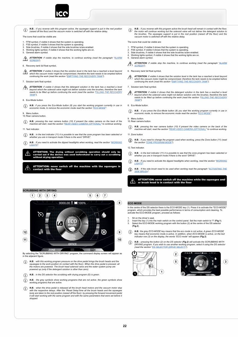
N.B. : if you reverse with this program active, the squeegee support is put in the rest position (raised off the floor) and the vacuum motor is switched off with the relative delay.
The icons that could be visible are:
1. FFM symbol, if visible it shows that the system is operating.2. FSS symbol, if visible it shows that the system is operating.3. Side brush/es, if visible it shows that the side brush/es is/are enabled.4. Working lights symbol, if visible it shows that the working lights are on.5. General alarm symbol.
ATTENTION: if visible stop the machine, to continue working (read the paragraph “ALARM SCREEN”).
6. Recovery tank full float symbol,
ATTENTION: if visible it shows that the solution level in the tank has a reached a level beyond which the vacuum motor might be compromised, therefore the tank needs to be emptied before continuing the work (read the section “EMPTYING THE RECOVERY TANK”).
7. Solution tank float symbol.
ATTENTION: if visible it shows that the detergent solution in the tank has a reached a level beyond which the solenoid valve might not deliver solution onto the brushes, therefore the tank needs to be filled up before continuing the work (read the section “FILLING THE RECOVERY TANK”).
8. Eco-Mode button.
N.B.: if you press the Eco-Mode button (8) you start the working program currently in use in economic mode, to remove the economic mode read the section “ECO MODE”.
9. Menu button.10. Rear camera button.
N.B.: pressing the rear camera button (10) if present the video camera on the back of the machine will start, read the section “REAR VIDEO CAMERA (OPTIONAL)” to continue working.
11. Text indicator.
N.B. : in the text indicator (11) it is possible to see that the zone program has been selected or whether you are in transport mode if there is the word “DRIVE”.
N.B. : If you need to activate the dipped headlights when working, read the section “WORKING LIGHTS”.
ATTENTION: The drying without scrubbing operation should only be carried out if the device was used beforehand to carry out a scrubbing without drying operation.
ATTENTION: never switch off the machine with the squeegee in contact with the floor
SCRUBBING WITH DRYING
OFFICE
0000.00 100%
9
10
8
12
11
1 52 63 74
By selecting the "SCRUBBING WITH DRYING” program, the command display screen will appear as in the adjacent figure.
N.B. : with this working program pressure on the drive pedal brings the brush heads and the squeegee to the work position (in contact with the floor). When the drive pedal is pressed, all the motors are powered. The brush head solenoid valve and the water system pump are powered up (only if the detergent solution is other than zero).
N.B. : in the DS selector the scrubbing with drying program (D) is green.
N.B. : the grey symbols show working programs that are not active. the green symbols show working programs that are active.
N.B. : when the drive pedal is released all the brush head motors and the vacuum motor stop with the respective delays. After the “Reset Delay”time all the brush heads and the squeegee body are taken to the rest position (raised off the floor). by pressing the forward movement pedal it will start working with the same program and with the same parameters that were set before it stopped.
N.B. : if you reverse with this program active the brush head will remain in contact with the floor, the motor will continue working but the solenoid valve will not deliver the detergent solution to the brushes. The squeegee support is put in the rest position (raised off the floor) and the vacuum motor is switched off with the relative delay.
The icons that could be visible are:
1. FFM symbol, if visible it shows that the system is operating.2. FSS symbol, if visible it shows that the system is operating.3. Side brush/es, if visible it shows that the side brush/es is/are enabled.4. Working lights symbol, if visible it shows that the working lights are on.5. General alarm symbol.
ATTENTION: if visible stop the machine, to continue working (read the paragraph “ALARM SCREEN”).
6. Recovery tank full float symbol,
ATTENTION: if visible it shows that the solution level in the tank has a reached a level beyond which the vacuum motor might be compromised, therefore the tank needs to be emptied before continuing the work (read the section “EMPTYING THE RECOVERY TANK”).
7. Solution tank float symbol.
ATTENTION: if visible it shows that the detergent solution in the tank has a reached a level beyond which the solenoid valve might not deliver solution onto the brushes, therefore the tank needs to be filled up before continuing the work (read the section “FILLING THE RECOVERY TANK”).
8. Eco-Mode button.
N.B. : if you press the Eco-Mode button (8) you start the working program currently in use in economic mode, to remove the economic mode read the section “ECO MODE”.
9. Menu button.10. Rear camera button.
N.B.: pressing the rear camera button (10) if present the video camera on the back of the machine will start, read the section “REAR VIDEO CAMERA (OPTIONAL)” to continue working.
11. Zone button
N.B. : if you need to change the program used when working, press the Zone button (11) (read the section “ZONE PROGRAM MODE”).
12. Text indicator.
N.B. : in the text indicator (11) it is possible to see that the zone program has been selected or whether you are in transport mode if there is the word “DRIVE”.
N.B. : If you need to activate the dipped headlights when working, read the section “WORKING LIGHTS”.
N.B. : If the side brush need to be used when working read the paragraph “ACTIVATING THE SIDE BRUSH”.
ATTENTION: never switch off the machine while the squeegee and/or brush head is in contact with the floor
ECO MODEIn the centre of the DS selector there is the ECO-MODE key (1). Press it to activate the "ECO-MODE" program, which provides the best possible performance in terms of consumption and cleaning. To activate the ECO-MODE program, proceed as follows:
1. Sit on the driver’s seat.2. Insert the key (1) into the main switch on the control panel. Set the main switch to "I" (Fig.1).3. Select the ECO-MODE working program with the button (2) at the centre of the DS selector
(Fig.2).
N.B.: the grey ECO-MODE key means that the eco mode is not active. A green ECO-MODE key means that economic mode is active. In addition, when ECO-MODE is active, on the text indicator row (3) on the display, the words “ECO mode” will appear (Fig.2).
N.B. : pressing the button (2) on the DS selector (Fig.2) will activate the SCRUBBING WITH DRYING program. If you wish to use another working program, select it using the DS selector (read the section “DS SELECTOR (DRIVE SELECT)”).
ECO mode
0000.00 100%2
5 3
211
ON
22
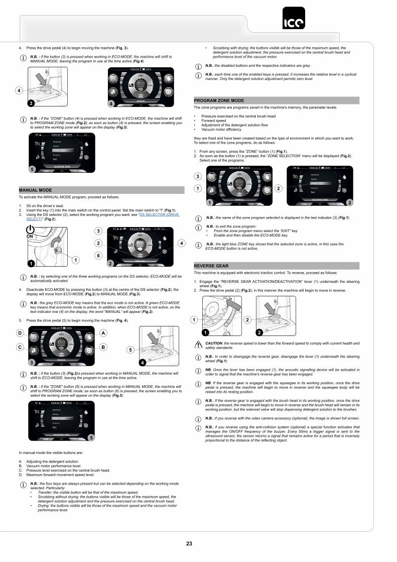
4. Press the drive pedal (4) to begin moving the machine (Fig. 3).
N.B. : if the button (2) is pressed when working in ECO-MODE, the machine will shift to MANUAL MODE, leaving the program in use at the time active (Fig.4).
N.B. : if the "ZONE" button (4) is pressed when working in ECO-MODE, the machine will shift to PROGRAM ZONE mode (Fig.2); as soon as button (4) is pressed, the screen enabling you to select the working zone will appear on the display (Fig.5).
MANUAL
0000.00 100%
43
4
Warehouse
Canteen
Office
Reception
Exit
SELEZIONE ZONE
0000.00 100%
5
MANUAL MODETo activate the MANUAL-MODE program, proceed as follows:
1. Sit on the driver’s seat.2. Insert the key (1) into the main switch on the control panel. Set the main switch to "I" (Fig.1).3. Using the DS selector (2), select the working program you want; see “DS SELECTOR (DRIVE
SELECT)” (Fig.2).
N.B. : by selecting one of the three working programs on the DS selector, ECO-MODE will be automatically activated.
4. Deactivate ECO-MODE by pressing the button (3) at the centre of the DS selector (Fig.2); the display will move from ECO-MODE (Fig.2) to MANUAL MODE (Fig.3).
N.B.: the grey ECO-MODE key means that the eco mode is not active. A green ECO-MODE key means that economic mode is active. In addition, when ECO-MODE is not active, on the text indicator row (4) on the display, the word "MANUAL” will appear (Fig.2).
5. Press the drive pedal (5) to begin moving the machine (Fig. 4).
N.B. : if the button (3) (Fig.2)is pressed when working in MANUAL MODE, the machine will shift to ECO-MODE, leaving the program in use at the time active.
N.B. : if the "ZONE" button (6) is pressed when working in MANUAL MODE, the machine will shift to PROGRAM ZONE mode; as soon as button (6) is pressed, the screen enabling you to select the working zone will appear on the display (Fig.5).
In manual mode the visible buttons are:
A. Adjusting the detergent solution.B. Vacuum motor performance level.C. Pressure level exercised on the central brush head.D. Maximum forward movement speed level.
N.B.: the four keys are always present but can be selected depending on the working mode selected. Particularly:• Transfer: the visible button will be that of the maximum speed.• Scrubbing without drying: the buttons visible will be those of the maximum speed, the
detergent solution adjustment and the pressure exercised on the central brush head.• Drying: the buttons visible will be those of the maximum speed and the vacuum motor
performance level.
ECO mode
0000.00 100%3
2 4
621
1
ON
MANUAL
0000.00 100%
3
D A
C B
4
5
Warehouse
Canteen
Office
Reception
Exit
SELEZIONE ZONE
0000.00 100%
5
• Scrubbing with drying: the buttons visible will be those of the maximum speed, the detergent solution adjustment, the pressure exercised on the central brush head and performance level of the vacuum motor.
N.B.: the disabled buttons and the respective indicators are grey.
N.B.: each time one of the enabled keys is pressed, it increases the relative level in a cyclical manner. Only the detergent solution adjustment permits zero level.
PROGRAM ZONE MODEThe zone programs are programs saved in the machine's memory, the parameter levels:
• Pressure exercised on the central brush head• Forward speed• Adjustment of the detergent solution flow• Vacuum motor efficiency
they are fixed and have been created based on the type of environment in which you want to work.To select one of the zone programs, do as follows:
1. From any screen, press the “ZONE” button (1) (Fig.1).2. As soon as the button (1) is pressed, the “ZONE SELECTION” menu will be displayed (Fig.2).
Select one of the programs.
N.B.: the name of the zone program selected is displayed in the text indicator (3) (Fig.1).
N.B.: to exit the zone program:• From the zone program menu select the “EXIT” key• Enable and then disable the ECO-MODE key.
N.B.: the light blue ZONE key shows that the selected zone is active, in this case the ECO-MODE button is not active.
MANUAL
0000.00 100%
Warehouse
Canteen
Office
Reception
Exit
SELEZIONE ZONE
0000.00 100%
1 2
1
3
2
REVERSE GEARThis machine is equipped with electronic traction control. To reverse, proceed as follows:
1. Engage the “REVERSE GEAR ACTIVATION/DEACTIVATION” lever (1) underneath the steering wheel (Fig.1).
2. Press the drive pedal (2) (Fig.2); in this manner the machine will begin to move in reverse.
CAUTION: the reverse speed is lower than the forward speed to comply with current health and safety standards.
N.B.: In order to disengage the reverse gear, disengage the lever (1) underneath the steering wheel (Fig.1).
NB: Once the lever has been engaged (1), the acoustic signalling device will be activated in order to signal that the machine's reverse gear has been engaged.
NB: If the reverse gear is engaged with the squeegee in its working position, once the drive pedal is pressed, the machine will begin to move in reverse and the squeegee body will be raised into its resting position.
N.B.: If the reverse gear is engaged with the brush head in its working position, once the drive pedal is pressed, the machine will begin to move in reverse and the brush head will remain in its working position, but the solenoid valve will stop dispensing detergent solution to the brushes.
N.B.: if you reverse with the video camera accessory (optional), the image is shown full screen.
N.B.: if you reverse using the anti-collision system (optional) a special function activates that manages the ON/OFF frequency of the buzzer. Every 50ms a trigger signal is sent to the ultrasound sensor, the sensor returns a signal that remains active for a period that is inversely proportional to the distance of the reflecting object.
21
1 2
23
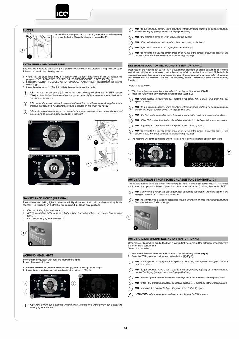
BUZZERThe machine is equipped with a buzzer. if you need to sound a warning, just press the button (1) on the steering column (Fig.1).
1
1
EXTRA BRUSH HEAD PRESSUREThis machine is capable of increasing the pressure exerted upon the brushes during the work cycle. This can be done in the following manner:
1. Check that the brush head body is in contact with the floor, if not select in the DS selector the programs “SCRUBBING WITH DRYING” OR “SCRUBBING WITHOUT DRYING” (Fig.1).
2. Engage the “EXTRA-PRESSURE ACTIVATION/DEACTIVATION” lever (1) underneath the steering wheel (Fig.2).
3. Press the drive pedal (2) (Fig.3) to initiate the machine's working cycle.
N.B. : as soon as the lever (1) is shifted the control display will show the “POWER” screen (Fig.4), in the middle of the screen there is a graphic symbol (3) and a numeric symbol (4), these represent a countdown.
N.B. : when the extra-pressure function is activated, the countdown starts. During this time, a pressure stronger than the standard pressure is exerted on the brush head body.
N.B.: at the end of the countdown you return to the working screen that was previously used and the pressure on the brush head goes back to standard.
2
3
2
3
Back
0000.00 100%
POWER
0000.00 100%
1
4
MAINTENANCE LIGHTS (OPTIONAL)The machine has blinking lights to increase visibility of the parts that could require controlling by the operator. The switch (1) on the front of the machine (Fig. 1) has three positions:
1. ON: the blinking lights are always on.2. AUTO: the blinking lights come on only the relative inspection hatches are opened (e.g. recovery
tank).3. OFF: the blinking lights are always off.
1
1
WORKING HEADLIGHTSThe machine is equipped with front and rear working lights.To start them do as follows.
1. With the machine on, press the menu button (1) on the working screen (Fig.1).2. Press the working lights activation - deactivation button (2) (Fig.2).
N.B.: if the symbol (2) is grey the working lights are not active, if the symbol (2) is green the working lights are active.
OFFICE
0000.00 100% 0000.00 100%
ECO mode
1
2
2
1
3
N.B. : to quit the menu screen, wait a short time without pressing anything, or else press on any point of the display (except one of the displayed buttons).
N.B. : the sidelights come on when the machine is started.
N.B. : if the side lights are activated the relative symbol (3) is displayed.
N.B.: if you want to switch off the lights press the button (2).
N.B. : to return to the working screen press on any point of the screen, except the edges of the display or else wait three seconds without touching anything.
DETERGENT SOLUTION RECYCLING SYSTEM (OPTIONAL)Upon request the machine can be fitted with a system that allows the detergent solution to be recycled so that productivity can be increased, since the number of stops needed to empty and fill the tanks is reduced. As a result less water and detergent are used, thereby making the operator safer, who comes into contact with the chemical products less frequently, and the operation is more environmentally friendly.
To start it do as follows.
1. With the machine on, press the menu button (1) on the working screen (Fig.1).2. Press the FLR system activation/deactivation button (2) (Fig.2).
N.B. : if the symbol (2) is grey the FLR system is not active, if the symbol (2) is green the FLR system is active.
N.B. : to quit the menu screen, wait a short time without pressing anything, or else press on any point of the display (except one of the displayed buttons).
N.B. : the FLR system activates when the electric pump in the machine's water system starts.
N.B. : if the FLR system is activated, the relative symbol (3) is displayed in the working screen.
N.B. : if you want to deactivate the FLR system press button (2) again.
N.B. : to return to the working screen press on any point of the screen, except the edges of the display or else wait three seconds without touching anything.
3. The machine will continue working until there is no more any detergent solution in both tanks.
OFFICE
0000.00 100% 0000.00 100%
ECO mode
1
2
2
1
3
AUTOMATIC REQUEST FOR TECHNICAL ASSISTANCE (OPTIONAL) 24The machine has an automatic service for activating an urgent technical assistance request. To activate this function, the operator only has to press the button under the hatch (1) bearing the symbol “SOS”.
N.B. : in order to activate this urgent technical assistance request the machine needs to be equipped with the FLEET MANAGEMENT kit.
N.B. : in order to send a technical assistance request the machine needs to be on and should be in a zone with data traffic coverage.
1
1
AUTOMATIC DETERGENT DOSING SYSTEM (OPTIONAL)Upon request, the machine can be fitted with a system that measures out the detergent separately from the water in the solution tank.To start it do as follows.
1. With the machine on, press the menu button (1) on the working screen (Fig.1).2. Press the FSS system activation/deactivation button (2) (Fig.2).
N.B. : if the symbol (2) is grey the FSS system is not active, if the symbol (2) is green the FSS system is active.
N.B. : to quit the menu screen, wait a short time without pressing anything, or else press on any point of the display (except one of the displayed buttons).
N.B.: the FSS system activates when the electric pump in the machine's water system starts.
N.B. : if the FSS system is activated, the relative symbol (3) is displayed in the working screen.
N.B. : if you want to deactivate the FSS system press button (2) again.
ATTENTION: before starting any work, remember to start the FSS system.
24
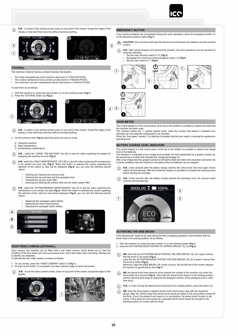
N.B. : to return to the working screen press on any point of the screen, except the edges of the display or else wait three seconds without touching anything.
OFFICE
0000.00 100% 0000.00 100%
ECO mode
1
2
2
1
3
TUTORIALThe machine's internal memory contains tutorials that explain:
• The initial commissioning of the machine (document in IT-EN-ES-FR-DE).• The routine maintenance to be carried out (document in IT-EN-ES-FR-DE).• The machine's use and maintenance manual (document in IT-EN-ES-FR-DE).
To start them do as follows.
1. With the machine on, press the menu button (1) on the working screen (Fig.1).2. Press the TUTORIAL button (2) (Fig.2).
N.B. : to return to the working screen press on any point of the screen, except the edges of the display or else wait three seconds without touching anything.
3. On the tutorial screen (Fig.3) select the topics you want to study:
A. Using the machine.B. Daily maintenance.C. Extraordinary maintenance.
N.B. : select the “USING THE MACHINE” key (A) to view the video explaining the stages for preparing the machine for work (Fig.3).
N.B.: select the “DAILY MAINTENANCE” KEY (B) to view the video explaining the maintenance to be carried out every day (Fig.3). When this button is selected the screen regarding the selection of the videos to view will be displayed (Fig.4), you can view the following tutorial videos:
• Draining and cleaning the recovery tank.• Cleaning the vacuum tube and the squeegee body.• Cleaning the vacuum motor filter.• Draining and cleaning the solution tank and the water system filter.
N.B.: select the “EXTRAORDINARY MAINTENANCE” key (C) to see the video explaining the maintenance to be carried out daily (Fig.3). When this button is selected the screen regarding the selection of the videos to view will be displayed (Fig.4), you can view the following tutorial videos:
• Replacing the squeegee rubber blades.• Replacing the brush head brushes.• Adjusting the squeegee rubber blades.
OFFICE
0000.00 100% 0000.00 100%
ECO mode
1
2
2
1
VIDEO TUTORIAL
Utilizzo della macchina
Manutenzione giornaliera
Interventi straordinari
Back3 4C
B
A
EMERGENCY BUTTONIf any serious problems are encountered during the work operations, press the emergency button (1) on the electrical system's carter (Fig.1).
CAUTION: This command interrupts the electrical circuit between the batteries and the machine system.
N.B.: After having stopped and resolved the problem, the work operations can be resumed by doing the following:• Set the main machine switch to “0” (Fig.2).• Disengage the mushroom-head emergency button (1) (Fig.3).• Set the main switch to "I" (Fig.4).
1 3
11
2
4
2
2
OFF
ON
REAR VIDEO CAMERA (OPTIONAL)Upon request, the machine can be fitted with a rear video camera, which allows you to view the condition of the floor where you have just passed over, and it also helps when reversing, allowing you to identify any obstacles.To activate the rear video camera, proceed as follows:
1. On any screen, press the “VIDEO CAMERA” button (1) (Fig.1).2. As soon as the button (1) is pressed, the video camera image is shown full screen.
N.B. : to exit the video camera screen, press on any point of the screen, except the edges of the display.
DRIVE
0000.00 100%
11
HOUR METERThe control display is in the control panel, at the top in the middle it is possible to observe the total time the machine has been used.The numbers before the "." symbol identify hours, while the number that follows it indicates hour decimals (an hour decimal corresponds to six minutes).When the “hour glass” symbol (1) is flashing it indicates that the hour meter is counting the appliance's operating time.
BATTERY CHARGE LEVEL INDICATORThe control display is in the control panel, at the top in the middle it is possible to observe the charge level of the batteries.The indicator is composed of two charge level symbols, the first represented by a graphic symbol (2), the second by a number that indicated the charge percentage (3).With a low charge level the graphic symbol (2) will start to flash and after a few seconds it will switch off, in these conditions take the machine to the place where its batteries can be charged.
N.B.: a few seconds after the battery charge reaches the critical level, the brush gear motors switch off automatically. With the remaining charge it is possible to complete the drying process before starting the recharge.
N.B.: A few seconds after the battery charge reaches the discharge level, the vacuum motor switches off automatically.
DRIVE
0000.00 100%3
21
ACTIVATING THE SIDE BRUSHIf the lateral brush needs to be used during the floor scrubbing operations, and therefore with the brush head in its working position, do as follows.
1. With the machine on, press the menu button (1) on the working screen (Fig.1).2. press the ACTIVATION-DEACTIVATION OF LATERAL BRUSH 1SL (2) (Fig.2).
NB: when the key ACTIVATING-DEACTIVATING THE SIDE BRUSH 1SL (2) is grey it shows that the brush is not active (Fig.2).when the key ACTIVATING-DEACTIVATING THE SIDE BRUSH 1SL (2) is green it shows that the brush is active (Fig.2).Moreover, when the SIDE BRUSH 1SL mode is active, the top left part of the screen displays the symbol (3) specifically for this (Fig.1).
NB: the lateral brush head starts to move towards the outside of the machine only when the drive pedal (4) is pressed (Fig.3). Only when the lateral brush head is in the working position will the solenoid valve begin to dispense the detergent solution (if the detergent level is other than zero).
N.B.: In order to bring the lateral brush head back to its resting position, press the button (2).
NB: when the drive pedal is released all the brush head motors stop with the respective delays. After the “Reset Delay”time all the brush heads are taken to the rest position (raised off the floor). Even if the lateral brush head is in a rest position, the lateral brush function is still active, in fact when the drive pedal (4) is operated all the brush heads are brought to the working position (in contact with the floor).
25
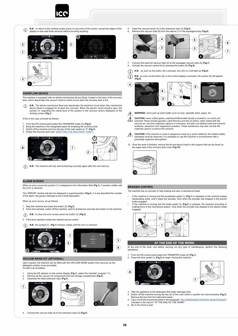
OVERFLOW DEVICEThe machine is equipped with an electro-mechanical device (float), located in the back of the recovery tank, which deactivates the vacuum motor's control circuit when the recovery tank is full.
N.B.: The electro-mechanical float only deactivates the electrical circuit when they mechanical device (float) is engaged for at least four seconds. When the electric circuit remains open, the symbol (1), regarding the critical level of the solution in the recovery tank,is displayed on the working screen (Fig.1).
If this is the case, proceed as follows:
1. From the DS control panel select the TRANSFER mode (A) (Fig.2).2. Bring the machine to the designated place for emptying the recovery tank.3. Switch off he machine and turn the key of the main switch to “0” (Fig.3).4. Empty the recovery tank (see “EMPTYING THE RECOVERY TANK”).
N.B.: The machine will only start functioning correctly again after the next start-up.
2
2
OFF
DRIVE
0000.00 100%
1
A 1
N.B. : to return to the working screen press on any point of the screen, except the edges of the display or else wait three seconds without touching anything.
33
OFFICE
0000.00 100% 0000.00 100%
ECO mode
1
2
2
1
3
ALARM SCREENWhen an error occurs the symbol (1) is displayed in the information field (Fig.1), it remains visible until the error is resolved.
The “ERROR” window will also be displayed in superimposition (Fig.2), in it are described the number of the alarm, the group it belongs to and a brief description.
When an error occurs, do as follows:
1. Stop the machine and press the button (2) (Fig.2).2. If the error persists, switch off the machine, wait for at least ten seconds and switch on the machine.
N.B.: to close the error screen press the button (3) (Fig.2).
3. If the error persists contact the nearest service centre.
N.B.: the symbol (1) (Fig.1) remains visible until the error is resolved.
OFFICE
0000.00 100%
ECO mode
0000.00 100%
Italiano
English
Spanish
French
German
Allarme 1Gruppo
Descrizione
Reset
?
1 2
1
23
4
VACUUM WAND KIT (OPTIONAL)Upon request, the machine can be fitted with the VACUUM WAND system that vacuums up the detergent solution more accurately.To start it do as follows.
1. Using the DS selector on the control display (Fig.1), select the “transfer” program” (1).2. Remove all the vacuum kit components from the storage compartment (Fig.2).3. Assemble the steel extension tube (Fig.3).
4. Connect the vacuum tube (4) to the extension tube (3) (Fig.4).
2 3Back
0000.00 100%
1
1
5. Insert the vacuum brush (5) in the extension tube (3) (Fig.5).6. Remove the vacuum tube (6) from the sleeve (7) in the squeegee body (Fig.6).
7. Connect the wand kit vacuum tube (4) to the squeegee vacuum tube (5) (Fig.7).8. Activate the vacuum control kit by pressing the button (8) (Fig.8).
N.B. : as soon as the button (8) is pressed, the LED on it will light up (Fig.8).
N.B.: as soon as the button (8) on the control display is pressed, the symbol (9) will appear (Fig.9).
WARNING: never pick up solid matter such as dust, cigarette stubs, paper, etc.
CAUTION: never collect gases, explosive/inflammable liquids or powders, nor acids and solvents! These include gasoline, paint thinners and fuel oil (which, when mixed with the vacuum air, can form explosive vapours or mixtures), and also non-diluted acids and solvents, acetones, aluminium and magnesium powders. These substances may also corrode the materials used to construct the machine.
CAUTION: if the machine is used in dangerous areas (e.g. petrol stations), the relative safety standards must be observed. It is forbidden to use the machine in environments with a potentially explosive atmosphere.
12. Once the work is finished, remove the kit and place it back in the support that can be found on the upper part of the recovery tank cover (Fig.10).
4
4
3
65
56
37
7
4
5
8
8
0000.00 100%
9
9
10
BRAKING CONTROLThe machine has an encoder to help braking and also a mechanical brake.
• If the machine is moving and the accelerator pedal (1) (Fig.1) is released, la the machine brakes decelerating softly, until it stops the encoder. Only when the encoder has stopped is the electric brake engaged.
• If the machine is moving and the brake pedal (2) (Fig.2) is pressed, the machine according to braking force of the mechanical system. Only when the encoder has stopped is the electric brake engaged.
1
1
2
2
AT THE END OF THE WORKAt the end of the work, and before carrying out any type of maintenance, perform the following operations:
1. From the DS control panel select the TRANSFER mode (A) (Fig.1).2. Press the drive pedal (1) (Fig.2) to begin moving the machine.
3. Take the appliance to the dedicated dirty water drainage area.4. Switch off the machine turning the key (2) of the main switch a quarter turn anti-clockwise (Fig.3).
Remove the key from the instrument panel.5. Carry out all the procedures listed in the paragraph “RECOMMENDED PERIODIC MAINTENANCE”
indicated in the column “AT THE END OF THE WORK”.6. Sit on the driver’s seat.
21
DRIVE
0000.00 100%
1
A
26
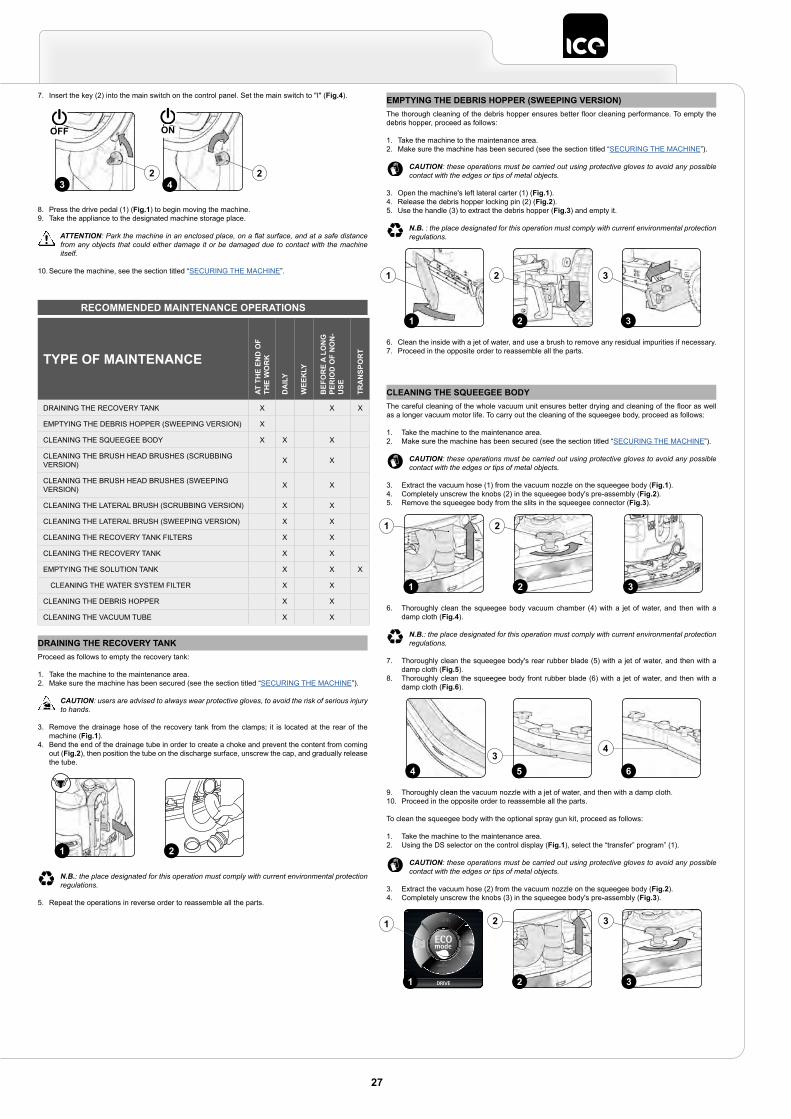
7. Insert the key (2) into the main switch on the control panel. Set the main switch to "I" (Fig.4).
8. Press the drive pedal (1) (Fig.1) to begin moving the machine.9. Take the appliance to the designated machine storage place.
ATTENTION: Park the machine in an enclosed place, on a flat surface, and at a safe distance from any objects that could either damage it or be damaged due to contact with the machine itself.
10. Secure the machine, see the section titled “SECURING THE MACHINE”.
3 42 2
ONOFF
RECOMMENDED MAINTENANCE OPERATIONS
DRAINING THE RECOVERY TANKProceed as follows to empty the recovery tank:
1. Take the machine to the maintenance area.2. Make sure the machine has been secured (see the section titled “SECURING THE MACHINE”).
CAUTION: users are advised to always wear protective gloves, to avoid the risk of serious injury to hands.
3. Remove the drainage hose of the recovery tank from the clamps; it is located at the rear of the machine (Fig.1).
4. Bend the end of the drainage tube in order to create a choke and prevent the content from coming out (Fig.2), then position the tube on the discharge surface, unscrew the cap, and gradually release the tube.
N.B.: the place designated for this operation must comply with current environmental protection regulations.
5. Repeat the operations in reverse order to reassemble all the parts.
21
EMPTYING THE DEBRIS HOPPER (SWEEPING VERSION)The thorough cleaning of the debris hopper ensures better floor cleaning performance. To empty the debris hopper, proceed as follows:
1. Take the machine to the maintenance area.2. Make sure the machine has been secured (see the section titled “SECURING THE MACHINE”).
CAUTION: these operations must be carried out using protective gloves to avoid any possible contact with the edges or tips of metal objects.
3. Open the machine's left lateral carter (1) (Fig.1).4. Release the debris hopper locking pin (2) (Fig.2).5. Use the handle (3) to extract the debris hopper (Fig.3) and empty it.
N.B. : the place designated for this operation must comply with current environmental protection regulations.
6. Clean the inside with a jet of water, and use a brush to remove any residual impurities if necessary.7. Proceed in the opposite order to reassemble all the parts.
2 31
21 3
CLEANING THE SQUEEGEE BODYThe careful cleaning of the whole vacuum unit ensures better drying and cleaning of the floor as well as a longer vacuum motor life. To carry out the cleaning of the squeegee body, proceed as follows:
1. Take the machine to the maintenance area.2. Make sure the machine has been secured (see the section titled “SECURING THE MACHINE”).
CAUTION: these operations must be carried out using protective gloves to avoid any possible contact with the edges or tips of metal objects.
3. Extract the vacuum hose (1) from the vacuum nozzle on the squeegee body (Fig.1).4. Completely unscrew the knobs (2) in the squeegee body's pre-assembly (Fig.2).5. Remove the squeegee body from the slits in the squeegee connector (Fig.3).
6. Thoroughly clean the squeegee body vacuum chamber (4) with a jet of water, and then with a damp cloth (Fig.4).
N.B.: the place designated for this operation must comply with current environmental protection regulations.
7. Thoroughly clean the squeegee body's rear rubber blade (5) with a jet of water, and then with a damp cloth (Fig.5).
8. Thoroughly clean the squeegee body front rubber blade (6) with a jet of water, and then with a damp cloth (Fig.6).
9. Thoroughly clean the vacuum nozzle with a jet of water, and then with a damp cloth.10. Proceed in the opposite order to reassemble all the parts.
To clean the squeegee body with the optional spray gun kit, proceed as follows:
1. Take the machine to the maintenance area.2. Using the DS selector on the control display (Fig.1), select the “transfer” program” (1).
CAUTION: these operations must be carried out using protective gloves to avoid any possible contact with the edges or tips of metal objects.
3. Extract the vacuum hose (2) from the vacuum nozzle on the squeegee body (Fig.2).4. Completely unscrew the knobs (3) in the squeegee body's pre-assembly (Fig.3).
2 31
1 2
64 53
4
DRIVE
0000.00 100%
1
1
32
2 3
27
TYPE OF MAINTENANCE
AT T
HE
END
OF
THE
WO
RK
DA
ILY
WEE
KLY
BEF
OR
E A
LON
G
PER
IOD
OF
NO
N-
USE
TRA
NSP
OR
T
DRAINING THE RECOVERY TANK X X X
EMPTYING THE DEBRIS HOPPER (SWEEPING VERSION) X
CLEANING THE SQUEEGEE BODY X X X
CLEANING THE BRUSH HEAD BRUSHES (SCRUBBING VERSION) X X
CLEANING THE BRUSH HEAD BRUSHES (SWEEPING VERSION) X X
CLEANING THE LATERAL BRUSH (SCRUBBING VERSION) X X
CLEANING THE LATERAL BRUSH (SWEEPING VERSION) X X
CLEANING THE RECOVERY TANK FILTERS X X
CLEANING THE RECOVERY TANK X X
EMPTYING THE SOLUTION TANK X X X
CLEANING THE WATER SYSTEM FILTER X X
CLEANING THE DEBRIS HOPPER X X
CLEANING THE VACUUM TUBE X X
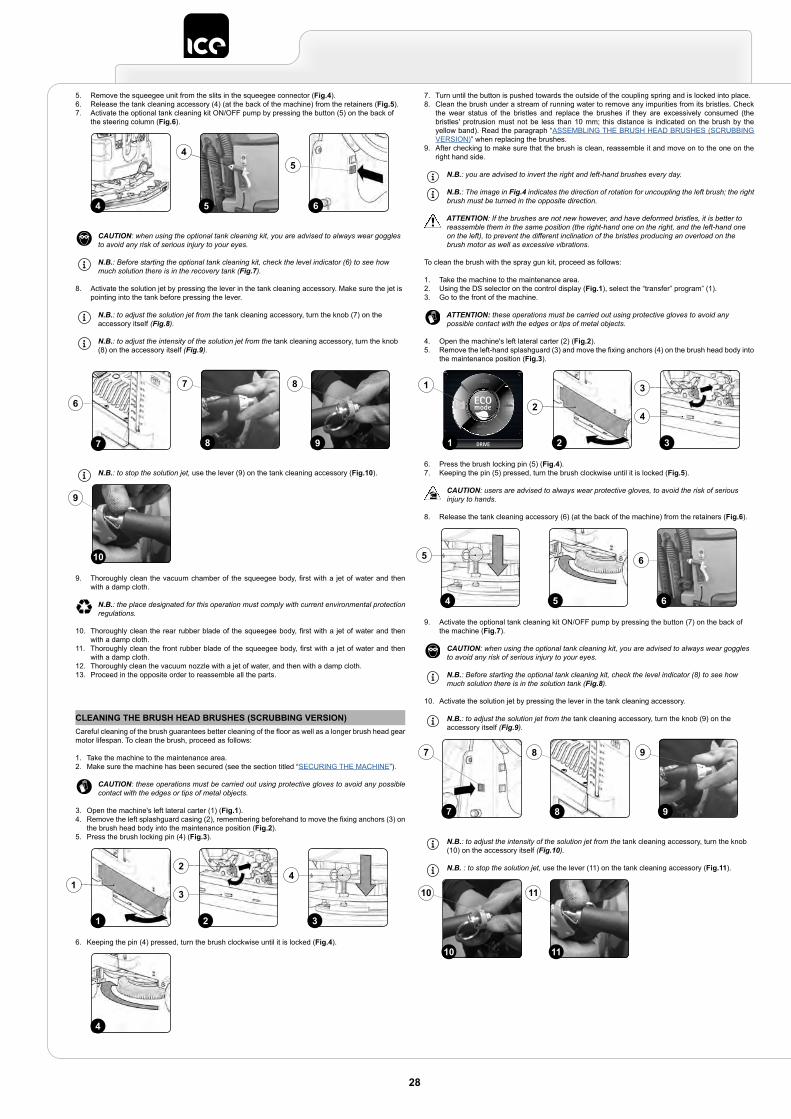
5. Remove the squeegee unit from the slits in the squeegee connector (Fig.4).6. Release the tank cleaning accessory (4) (at the back of the machine) from the retainers (Fig.5).7. Activate the optional tank cleaning kit ON/OFF pump by pressing the button (5) on the back of
the steering column (Fig.6).
CAUTION: when using the optional tank cleaning kit, you are advised to always wear goggles to avoid any risk of serious injury to your eyes.
N.B.: Before starting the optional tank cleaning kit, check the level indicator (6) to see how much solution there is in the recovery tank (Fig.7).
8. Activate the solution jet by pressing the lever in the tank cleaning accessory. Make sure the jet is pointing into the tank before pressing the lever.
N.B.: to adjust the solution jet from the tank cleaning accessory, turn the knob (7) on the accessory itself (Fig.8).
N.B.: to adjust the intensity of the solution jet from the tank cleaning accessory, turn the knob (8) on the accessory itself (Fig.9).
N.B.: to stop the solution jet, use the lever (9) on the tank cleaning accessory (Fig.10).
9. Thoroughly clean the vacuum chamber of the squeegee body, first with a jet of water and then with a damp cloth.
N.B.: the place designated for this operation must comply with current environmental protection regulations.
10. Thoroughly clean the rear rubber blade of the squeegee body, first with a jet of water and then with a damp cloth.
11. Thoroughly clean the front rubber blade of the squeegee body, first with a jet of water and then with a damp cloth.
12. Thoroughly clean the vacuum nozzle with a jet of water, and then with a damp cloth.13. Proceed in the opposite order to reassemble all the parts.
5
4
6
5
4
7 8
6
7
9
8
10
9
CLEANING THE BRUSH HEAD BRUSHES (SCRUBBING VERSION)Careful cleaning of the brush guarantees better cleaning of the floor as well as a longer brush head gear motor lifespan. To clean the brush, proceed as follows:
1. Take the machine to the maintenance area.2. Make sure the machine has been secured (see the section titled “SECURING THE MACHINE”).
CAUTION: these operations must be carried out using protective gloves to avoid any possible contact with the edges or tips of metal objects.
3. Open the machine's left lateral carter (1) (Fig.1).4. Remove the left splashguard casing (2), remembering beforehand to move the fixing anchors (3) on
the brush head body into the maintenance position (Fig.2).5. Press the brush locking pin (4) (Fig.3).
6. Keeping the pin (4) pressed, turn the brush clockwise until it is locked (Fig.4).
31 2
1
2
3
4
4
7. Turn until the button is pushed towards the outside of the coupling spring and is locked into place.8. Clean the brush under a stream of running water to remove any impurities from its bristles. Check
the wear status of the bristles and replace the brushes if they are excessively consumed (the bristles' protrusion must not be less than 10 mm; this distance is indicated on the brush by the yellow band). Read the paragraph “ASSEMBLING THE BRUSH HEAD BRUSHES (SCRUBBING VERSION)” when replacing the brushes.
9. After checking to make sure that the brush is clean, reassemble it and move on to the one on the right hand side.
N.B.: you are advised to invert the right and left-hand brushes every day.
N.B.: The image in Fig.4 indicates the direction of rotation for uncoupling the left brush; the right brush must be turned in the opposite direction.
ATTENTION: If the brushes are not new however, and have deformed bristles, it is better to reassemble them in the same position (the right-hand one on the right, and the left-hand one on the left), to prevent the different inclination of the bristles producing an overload on the brush motor as well as excessive vibrations.
To clean the brush with the spray gun kit, proceed as follows:
1. Take the machine to the maintenance area.2. Using the DS selector on the control display (Fig.1), select the “transfer” program” (1).3. Go to the front of the machine.
ATTENTION: these operations must be carried out using protective gloves to avoid any possible contact with the edges or tips of metal objects.
4. Open the machine's left lateral carter (2) (Fig.2).5. Remove the left-hand splashguard (3) and move the fixing anchors (4) on the brush head body into
the maintenance position (Fig.3).
6. Press the brush locking pin (5) (Fig.4).7. Keeping the pin (5) pressed, turn the brush clockwise until it is locked (Fig.5).
CAUTION: users are advised to always wear protective gloves, to avoid the risk of serious injury to hands.
8. Release the tank cleaning accessory (6) (at the back of the machine) from the retainers (Fig.6).
9. Activate the optional tank cleaning kit ON/OFF pump by pressing the button (7) on the back of the machine (Fig.7).
CAUTION: when using the optional tank cleaning kit, you are advised to always wear goggles to avoid any risk of serious injury to your eyes.
N.B.: Before starting the optional tank cleaning kit, check the level indicator (8) to see how much solution there is in the solution tank (Fig.8).
10. Activate the solution jet by pressing the lever in the tank cleaning accessory.
N.B.: to adjust the solution jet from the tank cleaning accessory, turn the knob (9) on the accessory itself (Fig.9).
N.B.: to adjust the intensity of the solution jet from the tank cleaning accessory, turn the knob (10) on the accessory itself (Fig.10).
N.B. : to stop the solution jet, use the lever (11) on the tank cleaning accessory (Fig.11).
DRIVE
0000.00 100%
1 2 3
2
3
4
1
54
5
6
6
97
97
8
8
10
10
11
11
28
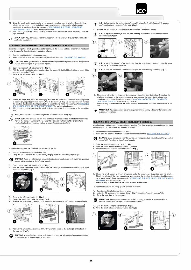
11. Clean the brush under running water to remove any impurities from its bristles. Check that the bristles are not worn; in the event of excessive wear, replace the brush (the bristles should be at least 10 mm long). Read the paragraph “ASSEMBLING THE BRUSH HEAD BRUSH (SCRUBBING VERSION)” when replacing the brush.
12. After checking to make sure that the brush is clean, reassemble it and move on to the one on the right hand side.
ATTENTION: the place designated for this operation must comply with current environmental protection regulations.
CLEANING THE BRUSH HEAD BRUSHES (SWEEPING VERSION)Careful cleaning of the brush guarantees better cleaning of the floor as well as a longer brush head gear motor lifespan. To clean the brush, proceed as follows:
1. Take the machine to the maintenance area.2. Make sure the machine has been secured (see the section titled “SECURING THE MACHINE”).
CAUTION: these operations must be carried out using protective gloves to avoid any possible contact with the edges or tips of metal objects.
3. Open the machine's left lateral carter (1) (Fig.1).4. With the brush head in its raised position, turn the knobs (2) that hold the left lateral carter (3) in
place anti-clockwise (Fig.2).5. Remove the left lateral carter (3) (Fig.3).
6. Extract the brush from inside the tunnel (Fig.4). Clean the brush under a stream of running water to remove any impurities from its bristles. Check the bristles. If they are excessively worn, replace the brushes (the bristles should protrude by at least 10mm). Read the paragraph “FITTING THE BRUSH HEAD BRUSHES (SWEEPING VERSION)” for replacing the brushes.
7. After checking to make sure that the brush is clean, reassemble it and move on to the one at the rear.
N.B. : you are advised to invert the right and left-hand brushes every day.
ATTENTION: If the brushes are not new, and have deformed bristles, it is better to reassemble them in the same position in order to prevent the different inclination of the bristles from overloading the brush motor, as well as to prevent excessive vibrations.
To clean the brush with the spray gun kit, proceed as follows:
1. Take the machine to the maintenance area.2. Using the DS selector on the control display (Fig.1), select the “transfer” program” (1).
CAUTION: these operations must be carried out using protective gloves to avoid any possible contact with the edges or tips of metal objects.
3. Open the machine's left lateral carter (2) (Fig.2).4. With the brush head in its raised position, turn the knobs (3) that hold the left lateral carter (4) in
place anti-clockwise (Fig.3).
5. Remove the left lateral carter (4) (Fig.4).6. Extract the brush from inside the tunnel (Fig.5).7. Release the tank cleaning accessory (5) (at the back of the machine) from the retainers (Fig.6).
8. Activate the optional tank cleaning kit ON/OFF pump by pressing the button (6) on the back of the machine (Fig.7).
CAUTION: when using the optional tank cleaning kit, you are advised to always wear goggles to avoid any risk of serious injury to your eyes.
2 31
2
3
31
4
32
3
4
2
Back
0000.00 100%
1
1
4
4
6
5
5
N.B. : Before starting the optional tank cleaning kit, check the level indicator (7) to see how much solution there is in the solution tank (Fig.8).
9. Activate the solution jet by pressing the lever in the tank cleaning accessory.
N.B. : to adjust the solution jet from the tank cleaning accessory, turn the knob (8) on the accessory itself (Fig.9).
N.B. : to adjust the intensity of the solution jet from the tank cleaning accessory, turn the knob (9) on the accessory itself (Fig.10).
N.B. : to stop the solution jet, use the lever (10) on the tank cleaning accessory (Fig.11).
10. Clean the brush under running water to remove any impurities from its bristles. Check that the bristles are not worn; in the event of excessive wear, replace the brush (the bristles should be at least 10 mm long). Read the paragraph “ASSEMBLING THE BRUSH HEAD BRUSH (SWEEPING VERSION)” when replacing the brush.
11. After checking to make sure that the brush is clean, reassemble it and move on to the one at the rear.
ATTENTION: the place designated for this operation must comply with current environmental protection regulations.
7
6
9
8
8
7
11
10
10
9
CLEANING THE LATERAL BRUSH (SCRUBBING VERSION)Careful cleaning of the brush guarantees better cleaning of the floor as well as a longer brush head gear motor lifespan. To clean the brush, proceed as follows:
1. Take the machine to the maintenance area.2. Make sure the machine has been secured (see the section titled “SECURING THE MACHINE”).
CAUTION: these operations must be carried out using protective gloves to avoid any possible contact with the edges or tips of metal objects.
3. Open the machine's right later carter (1) (Fig.1).4. Move the brush release lever downwards (2) (Fig.2).5. Remove the brush from the lateral brush head (Fig.3).
6. Clean the brush under a stream of running water to remove any impurities from its bristles. Check the bristles. If they are excessively worn, replace the brushes (the bristles should protrude by at least 10mm). Read the paragraph “ASSEMBLING THE SIDE BRUSH 1SL (SCRUBBING VERSION)” when replacing the brush.
7. After checking to make sure that the brush is clean, reassemble it.
To clean the brush with the spray gun kit, proceed as follows:
1. Take the machine to the maintenance area.2. Using the DS selector on the control display (Fig.1), select the “transfer” program” (1).3. Go to the front right of the machine.
ATTENTION: these operations must be carried out using protective gloves to avoid any possible contact with the edges or tips of metal objects.
4. Open the machine's right later carter (2) (Fig.2).5. Move the brush release lever downwards (3) (Fig.3).
2 31
1 2
32
2 3
Back
0000.00 100%
1
1
29
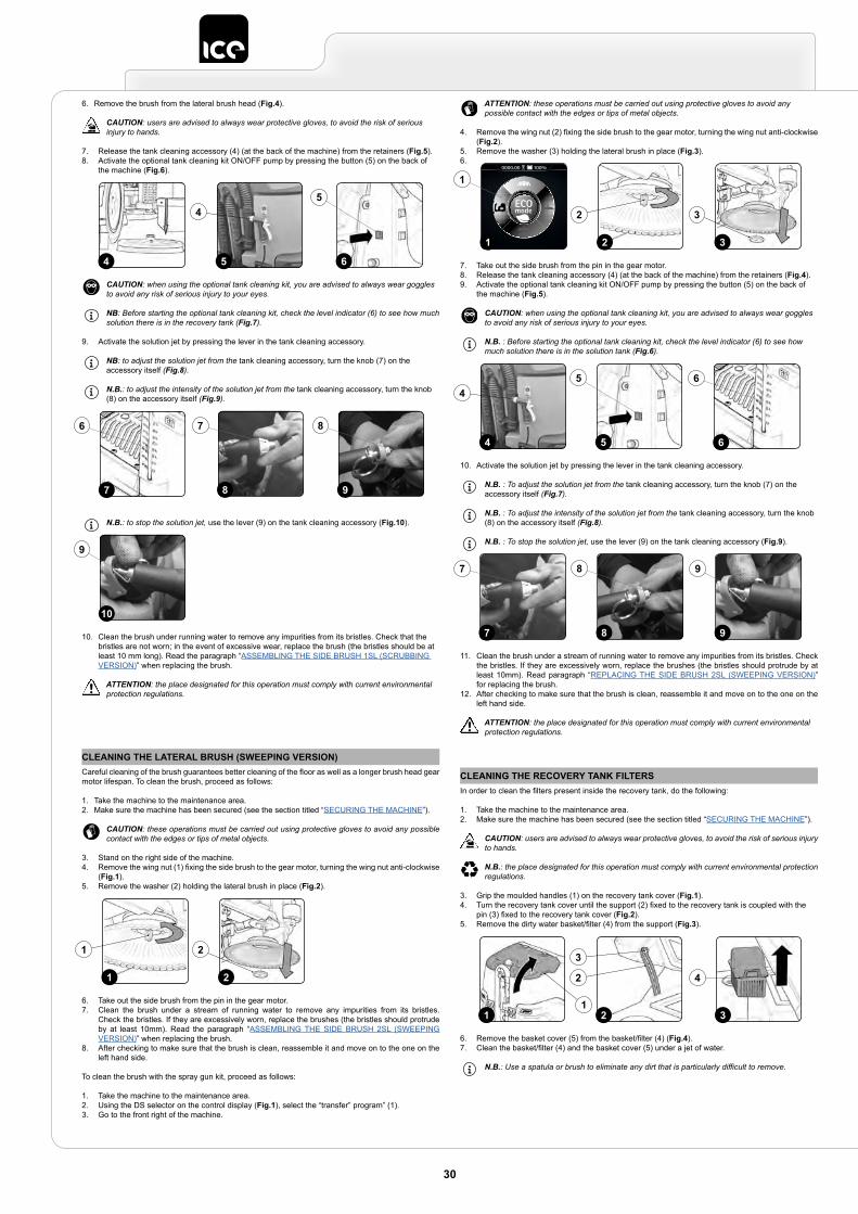
6. Remove the brush from the lateral brush head (Fig.4).
CAUTION: users are advised to always wear protective gloves, to avoid the risk of serious injury to hands.
7. Release the tank cleaning accessory (4) (at the back of the machine) from the retainers (Fig.5).8. Activate the optional tank cleaning kit ON/OFF pump by pressing the button (5) on the back of
the machine (Fig.6).
CAUTION: when using the optional tank cleaning kit, you are advised to always wear goggles to avoid any risk of serious injury to your eyes.
NB: Before starting the optional tank cleaning kit, check the level indicator (6) to see how much solution there is in the recovery tank (Fig.7).
9. Activate the solution jet by pressing the lever in the tank cleaning accessory.
NB: to adjust the solution jet from the tank cleaning accessory, turn the knob (7) on the accessory itself (Fig.8).
N.B.: to adjust the intensity of the solution jet from the tank cleaning accessory, turn the knob (8) on the accessory itself (Fig.9).
N.B.: to stop the solution jet, use the lever (9) on the tank cleaning accessory (Fig.10).
10. Clean the brush under running water to remove any impurities from its bristles. Check that the bristles are not worn; in the event of excessive wear, replace the brush (the bristles should be at least 10 mm long). Read the paragraph “ASSEMBLING THE SIDE BRUSH 1SL (SCRUBBING VERSION)” when replacing the brush.
ATTENTION: the place designated for this operation must comply with current environmental protection regulations.
6
5
5
4
4
9
8
8
7
7
6
10
9
CLEANING THE RECOVERY TANK FILTERSIn order to clean the filters present inside the recovery tank, do the following:
1. Take the machine to the maintenance area.2. Make sure the machine has been secured (see the section titled “SECURING THE MACHINE”).
CAUTION: users are advised to always wear protective gloves, to avoid the risk of serious injury to hands.
N.B.: the place designated for this operation must comply with current environmental protection regulations.
3. Grip the moulded handles (1) on the recovery tank cover (Fig.1).4. Turn the recovery tank cover until the support (2) fixed to the recovery tank is coupled with the
pin (3) fixed to the recovery tank cover (Fig.2).5. Remove the dirty water basket/filter (4) from the support (Fig.3).
6. Remove the basket cover (5) from the basket/filter (4) (Fig.4).7. Clean the basket/filter (4) and the basket cover (5) under a jet of water.
N.B.: Use a spatula or brush to eliminate any dirt that is particularly difficult to remove.
3211
42
3
CLEANING THE LATERAL BRUSH (SWEEPING VERSION)Careful cleaning of the brush guarantees better cleaning of the floor as well as a longer brush head gear motor lifespan. To clean the brush, proceed as follows:
1. Take the machine to the maintenance area.2. Make sure the machine has been secured (see the section titled “SECURING THE MACHINE”).
CAUTION: these operations must be carried out using protective gloves to avoid any possible contact with the edges or tips of metal objects.
3. Stand on the right side of the machine.4. Remove the wing nut (1) fixing the side brush to the gear motor, turning the wing nut anti-clockwise
(Fig.1).5. Remove the washer (2) holding the lateral brush in place (Fig.2).
6. Take out the side brush from the pin in the gear motor.7. Clean the brush under a stream of running water to remove any impurities from its bristles.
Check the bristles. If they are excessively worn, replace the brushes (the bristles should protrude by at least 10mm). Read the paragraph “ASSEMBLING THE SIDE BRUSH 2SL (SWEEPING VERSION)” when replacing the brush.
8. After checking to make sure that the brush is clean, reassemble it and move on to the one on the left hand side.
To clean the brush with the spray gun kit, proceed as follows:
1. Take the machine to the maintenance area.2. Using the DS selector on the control display (Fig.1), select the “transfer” program” (1).3. Go to the front right of the machine.
2
2
1
1
ATTENTION: these operations must be carried out using protective gloves to avoid any possible contact with the edges or tips of metal objects.
4. Remove the wing nut (2) fixing the side brush to the gear motor, turning the wing nut anti-clockwise (Fig.2).
5. Remove the washer (3) holding the lateral brush in place (Fig.3).6.
7. Take out the side brush from the pin in the gear motor.8. Release the tank cleaning accessory (4) (at the back of the machine) from the retainers (Fig.4).9. Activate the optional tank cleaning kit ON/OFF pump by pressing the button (5) on the back of
the machine (Fig.5).
CAUTION: when using the optional tank cleaning kit, you are advised to always wear goggles to avoid any risk of serious injury to your eyes.
N.B. : Before starting the optional tank cleaning kit, check the level indicator (6) to see how much solution there is in the solution tank (Fig.6).
10. Activate the solution jet by pressing the lever in the tank cleaning accessory.
N.B. : To adjust the solution jet from the tank cleaning accessory, turn the knob (7) on the accessory itself (Fig.7).
N.B. : To adjust the intensity of the solution jet from the tank cleaning accessory, turn the knob (8) on the accessory itself (Fig.8).
N.B. : To stop the solution jet, use the lever (9) on the tank cleaning accessory (Fig.9).
11. Clean the brush under a stream of running water to remove any impurities from its bristles. Check the bristles. If they are excessively worn, replace the brushes (the bristles should protrude by at least 10mm). Read paragraph “REPLACING THE SIDE BRUSH 2SL (SWEEPING VERSION)” for replacing the brush.
12. After checking to make sure that the brush is clean, reassemble it and move on to the one on the left hand side.
ATTENTION: the place designated for this operation must comply with current environmental protection regulations.
3
3
Back
0000.00 100%
1
1
2
2
4
4
5 6
65
7
7
9
9
8
8
30
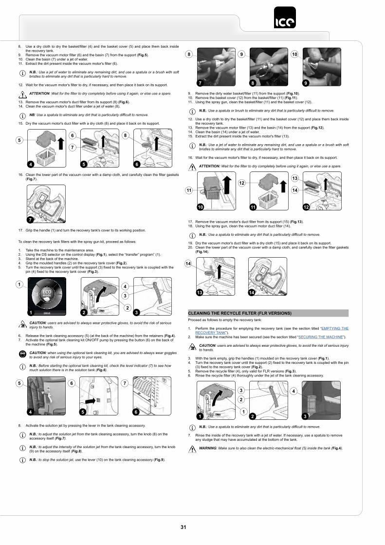
8. Use a dry cloth to dry the basket/filter (4) and the basket cover (5) and place them back inside the recovery tank.
9. Remove the vacuum motor filter (6) and the basin (7) from the support (Fig.5).10. Clean the basin (7) under a jet of water.11. Extract the dirt present inside the vacuum motor's filter (6).
N.B.: Use a jet of water to eliminate any remaining dirt, and use a spatula or a brush with soft bristles to eliminate any dirt that is particularly hard to remove.
12. Wait for the vacuum motor's filter to dry, if necessary, and then place it back on its support.
ATTENTION: Wait for the filter to dry completely before using it again, or else use a spare.
13. Remove the vacuum motor's duct filter from its support (8) (Fig.6).14. Clean the vacuum motor's duct filter under a jet of water (8).
NB: Use a spatula to eliminate any dirt that is particularly difficult to remove.
15. Dry the vacuum motor's duct filter with a dry cloth (8) and place it back on its support.
16. Clean the lower part of the vacuum cover with a damp cloth, and carefully clean the filter gaskets (Fig.7).
17. Grip the handle (1) and turn the recovery tank's cover to its working position.
To clean the recovery tank filters with the spray gun kit, proceed as follows:
1. Take the machine to the maintenance area.2. Using the DS selector on the control display (Fig.1), select the “transfer” program” (1).3. Stand at the back of the machine.4. Grip the moulded handles (2) on the recovery tank cover (Fig.2).5. Turn the recovery tank cover until the support (3) fixed to the recovery tank is coupled with the
pin (4) fixed to the recovery tank cover (Fig.3).
CAUTION: users are advised to always wear protective gloves, to avoid the risk of serious injury to hands.
6. Release the tank cleaning accessory (5) (at the back of the machine) from the retainers (Fig.4).7. Activate the optional tank cleaning kit ON/OFF pump by pressing the button (6) on the back of
the machine (Fig.5).
CAUTION: when using the optional tank cleaning kit, you are advised to always wear goggles to avoid any risk of serious injury to your eyes.
N.B.: Before starting the optional tank cleaning kit, check the level indicator (7) to see how much solution there is in the solution tank (Fig.6).
8. Activate the solution jet by pressing the lever in the tank cleaning accessory.
N.B.: to adjust the solution jet from the tank cleaning accessory, turn the knob (8) on the accessory itself (Fig.7).
N.B.: to adjust the intensity of the solution jet from the tank cleaning accessory, turn the knob (9) on the accessory itself (Fig.8).
N.B.: to stop the solution jet, use the lever (10) on the tank cleaning accessory (Fig.9).
5
6
7
6
8
4
5
7
DRIVE
0000.00 100%
31 22
3
41
4 5 6
5 6 7
9. Remove the dirty water basket/filter (11) from the support (Fig.10).10. Remove the basket cover (12) from the basket/filter (11) (Fig.11).11. Using the spray gun, clean the basket/filter (11) and the basket cover (12).
N.B.: Use a spatula or brush to eliminate any dirt that is particularly difficult to remove.
12. Use a dry cloth to dry the basket/filter (11) and the basket cover (12) and place them back inside the recovery tank.
13. Remove the vacuum motor filter (13) and the basin (14) from the support (Fig.12).14. Clean the basin (14) under a jet of water.15. Extract the dirt present inside the vacuum motor's filter (13).
N.B.: Use a jet of water to eliminate any remaining dirt, and use a spatula or a brush with soft bristles to eliminate any dirt that is particularly hard to remove.
16. Wait for the vacuum motor's filter to dry, if necessary, and then place it back on its support.
ATTENTION: Wait for the filter to dry completely before using it again, or else use a spare.
17. Remove the vacuum motor's duct filter from its support (15) (Fig.13).18. Using the spray gun, clean the vacuum motor duct filter (14).
N.B.: Use a spatula to eliminate any dirt that is particularly difficult to remove.
19. Dry the vacuum motor's duct filter with a dry cloth (15) and place it back on its support.20. Clean the lower part of the vacuum cover with a damp cloth, and carefully clean the filter gaskets
(Fig.14).
9
10
8
9
7
8
12
13
14
10 11
1211
1413
14
CLEANING THE RECYCLE FILTER (FLR VERSIONS)Proceed as follows to empty the recovery tank:
1. Perform the procedure for emptying the recovery tank (see the section titled “EMPTYING THE RECOVERY TANK”).
2. Make sure the machine has been secured (see the section titled “SECURING THE MACHINE”).
CAUTION: users are advised to always wear protective gloves, to avoid the risk of serious injury to hands.
3. With the tank empty, grip the handles (1) moulded on the recovery tank cover (Fig.1).4. Turn the recovery tank cover until the support (2) fixed to the recovery tank is coupled with the pin
(3) fixed to the recovery tank cover (Fig.2).5. Remove the recycle filter (4), only valid for FLR versions (Fig.3).6. Rinse the recycle filter (4) thoroughly under the jet of the tank cleaning accessory.
N.B.: Use a spatula to eliminate any dirt that is particularly difficult to remove.
7. Rinse the inside of the recovery tank with a jet of water. If necessary, use a spatula to remove any sludge that may have accumulated at the bottom of the tank.
WARNING: Make sure to also clean the electric-mechanical float (5) inside the tank (Fig.4).
3
4
211
2
3
31
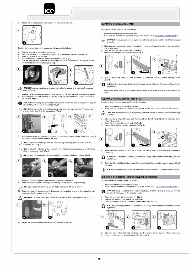
8. Repeat the operations in reverse order to reassemble all the parts.
To clean the recovery tank with the spray gun kit, proceed as follows:
1. Take the machine to the maintenance area.2. Using the DS selector on the control display (Fig.1), select the “transfer” program” (1).3. Stand at the back of the machine.4. Grip the moulded handles (2) on the recovery tank cover (Fig.2).5. Turn the recovery tank cover until the support (3) fixed to the recovery tank is coupled with the
pin (4) fixed to the recovery tank cover (Fig.3).
CAUTION: users are advised to always wear protective gloves, to avoid the risk of serious injury to hands.
6. Release the tank cleaning accessory (5) (at the back of the machine) from the retainers (Fig.4).7. Activate the optional tank cleaning kit ON/OFF pump by pressing the button (6) on the back of
the machine (Fig.5).
CAUTION: when using the optional tank cleaning kit, you are advised to always wear goggles to avoid any risk of serious injury to your eyes.
N.B.: Before starting the optional tank cleaning kit, check the level indicator (7) to see how much solution there is in the solution tank (Fig.6).
8. Activate the solution jet by pressing the lever in the tank cleaning accessory. Make sure the jet is pointing into the tank before pressing the lever.
N.B.: to adjust the solution jet from the tank cleaning accessory, turn the knob (8) on the accessory itself (Fig.7).
N.B.: to adjust the intensity of the solution jet from the tank cleaning accessory, turn the knob (9) on the accessory itself (Fig.8).
N.B.: to stop the solution jet, use the lever (10) on the tank cleaning accessory (Fig.9).
9. Remove the recycle filter (11), only valid for FLR versions (Fig.10).10. Rinse the recycle filter (11) thoroughly under the jet of the tank cleaning accessory.
N.B.: Use a spatula to eliminate any dirt that is particularly difficult to remove.
11. Rinse the inside of the recovery tank, if necessary use a spatula to remove the sludge that has accumulated at the bottom of the tank.
WARNING: Be sure to also clean the electro-mechanical float (12) inside the tank (Fig.12).
12. Repeat the operations in reverse order to reassemble all the parts.
4
5
DRIVE
0000.00 100%
31 22
3
41
4 5 6
5 6 7
9
10
8
9
7
8
11
12
10
11
EMPTYING THE SOLUTION TANK
Proceed as follows to empty the solution tank:
1. Take the machine to the maintenance area.2. Make sure the machine has been secured (see the section titled “SECURING THE MACHINE”).
CAUTION: users are advised to always wear protective gloves, to avoid the risk of serious injury to hands.
3. Close the tap's output flow, and shift the knob (1) on the left hand side of the steering column (Fig.1) downward.
4. Open the machine's left lateral hatch (2) (Fig.2).5. Remove the detergent solution filter cap (3) (Fig.3).
6. Open the tap's output flow, and shift the knob (1) on the left hand side of the steering column upward.
N.B.: the place designated for this operation must comply with current environmental protection regulations.
7. When the solution tank is empty, repeat the operations in the reverse order to reassemble all the parts.
2 31
1
23
CLEANING THE WATER SYSTEM FILTERIn order to clean the water system's filter, do the following:
1. Take the machine to the maintenance area.2. Make sure the machine has been secured (see the section titled “SECURING THE MACHINE”).
CAUTION: users are advised to always wear protective gloves, to avoid the risk of serious injury to hands.
3. Close the tap's output flow, and shift the knob (1) on the left hand side of the steering column (Fig.1) downward.
4. Open the machine's left lateral hatch (2) (Fig.2).5. Unscrew the detergent solution filter cap (3) (Fig.3).
6. Rinse the filter cartridge under a jet of water, and use a brush to eliminate any impurities, if necessary.
N.B.: the place designated for this operation must comply with current environmental protection regulations.
7. Once the filter cartridge is clean, repeat the operations in the opposite order to reassemble all the parts.
N.B.: For the sweeping versions, the water system filter is located on the right of the machine.
2 31
1
23
CLEANING THE DEBRIS HOPPER (SWEEPING VERSION)To clean the debris hopper, proceed as follows:
1. Take the machine to the maintenance area.2. Make sure the machine has been secured (see the section titled “SECURING THE MACHINE”).
CAUTION: these operations must be carried out using protective gloves to avoid any possible contact with the edges or tips of metal objects.
3. Open the machine's left lateral carter (1) (Fig.1).4. Release the debris hopper locking pin (2) (Fig.2).5. Use the handle (3) to extract the debris hopper (Fig.3) and empty it.
N.B. : the place designated for this operation must comply with current environmental protection regulations.
6. Clean the inside with a jet of water, and use a brush to remove any residual impurities if necessary.7. Proceed in the opposite order to reassemble all the parts.
2 31
21 3
32
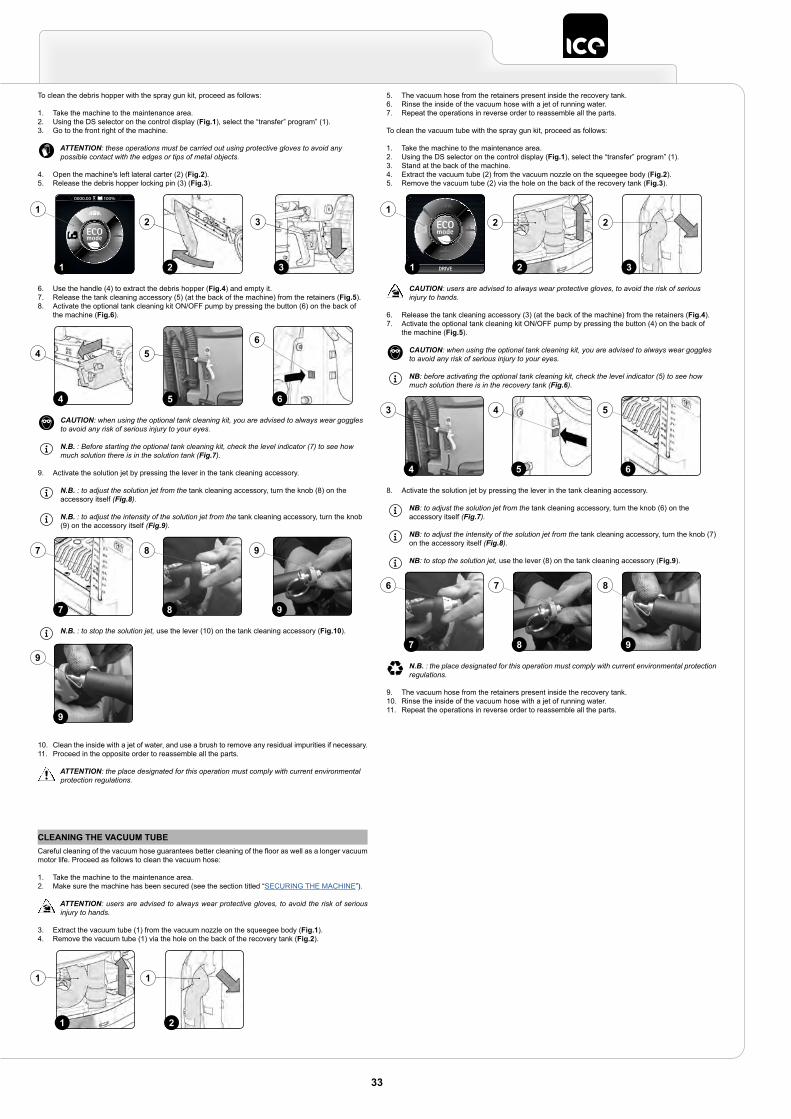
To clean the debris hopper with the spray gun kit, proceed as follows:
1. Take the machine to the maintenance area.2. Using the DS selector on the control display (Fig.1), select the “transfer” program” (1).3. Go to the front right of the machine.
ATTENTION: these operations must be carried out using protective gloves to avoid any possible contact with the edges or tips of metal objects.
4. Open the machine's left lateral carter (2) (Fig.2).5. Release the debris hopper locking pin (3) (Fig.3).
6. Use the handle (4) to extract the debris hopper (Fig.4) and empty it.7. Release the tank cleaning accessory (5) (at the back of the machine) from the retainers (Fig.5).8. Activate the optional tank cleaning kit ON/OFF pump by pressing the button (6) on the back of
the machine (Fig.6).
CAUTION: when using the optional tank cleaning kit, you are advised to always wear goggles to avoid any risk of serious injury to your eyes.
N.B. : Before starting the optional tank cleaning kit, check the level indicator (7) to see how much solution there is in the solution tank (Fig.7).
9. Activate the solution jet by pressing the lever in the tank cleaning accessory.
N.B. : to adjust the solution jet from the tank cleaning accessory, turn the knob (8) on the accessory itself (Fig.8).
N.B. : to adjust the intensity of the solution jet from the tank cleaning accessory, turn the knob (9) on the accessory itself (Fig.9).
N.B. : to stop the solution jet, use the lever (10) on the tank cleaning accessory (Fig.10).
10. Clean the inside with a jet of water, and use a brush to remove any residual impurities if necessary.11. Proceed in the opposite order to reassemble all the parts.
ATTENTION: the place designated for this operation must comply with current environmental protection regulations.
32
32
Back
0000.00 100%
1
1
5
5
64
46
8
8
9
9
7
7
9
9
CLEANING THE VACUUM TUBECareful cleaning of the vacuum hose guarantees better cleaning of the floor as well as a longer vacuum motor life. Proceed as follows to clean the vacuum hose:
1. Take the machine to the maintenance area.2. Make sure the machine has been secured (see the section titled “SECURING THE MACHINE”).
ATTENTION: users are advised to always wear protective gloves, to avoid the risk of serious injury to hands.
3. Extract the vacuum tube (1) from the vacuum nozzle on the squeegee body (Fig.1).4. Remove the vacuum tube (1) via the hole on the back of the recovery tank (Fig.2).
21
1 1
5. The vacuum hose from the retainers present inside the recovery tank.6. Rinse the inside of the vacuum hose with a jet of running water.7. Repeat the operations in reverse order to reassemble all the parts.
To clean the vacuum tube with the spray gun kit, proceed as follows:
1. Take the machine to the maintenance area.2. Using the DS selector on the control display (Fig.1), select the “transfer” program” (1).3. Stand at the back of the machine.4. Extract the vacuum tube (2) from the vacuum nozzle on the squeegee body (Fig.2).5. Remove the vacuum tube (2) via the hole on the back of the recovery tank (Fig.3).
CAUTION: users are advised to always wear protective gloves, to avoid the risk of serious injury to hands.
6. Release the tank cleaning accessory (3) (at the back of the machine) from the retainers (Fig.4).7. Activate the optional tank cleaning kit ON/OFF pump by pressing the button (4) on the back of
the machine (Fig.5).
CAUTION: when using the optional tank cleaning kit, you are advised to always wear goggles to avoid any risk of serious injury to your eyes.
NB: before activating the optional tank cleaning kit, check the level indicator (5) to see how much solution there is in the recovery tank (Fig.6).
8. Activate the solution jet by pressing the lever in the tank cleaning accessory.
NB: to adjust the solution jet from the tank cleaning accessory, turn the knob (6) on the accessory itself (Fig.7).
NB: to adjust the intensity of the solution jet from the tank cleaning accessory, turn the knob (7) on the accessory itself (Fig.8).
NB: to stop the solution jet, use the lever (8) on the tank cleaning accessory (Fig.9).
N.B. : the place designated for this operation must comply with current environmental protection regulations.
9. The vacuum hose from the retainers present inside the recovery tank.10. Rinse the inside of the vacuum hose with a jet of running water.11. Repeat the operations in reverse order to reassemble all the parts.
DRIVE
0000.00 100%
1
1
32
2 2
4 5 6
3 4 5
9
8
8
7
7
6
33
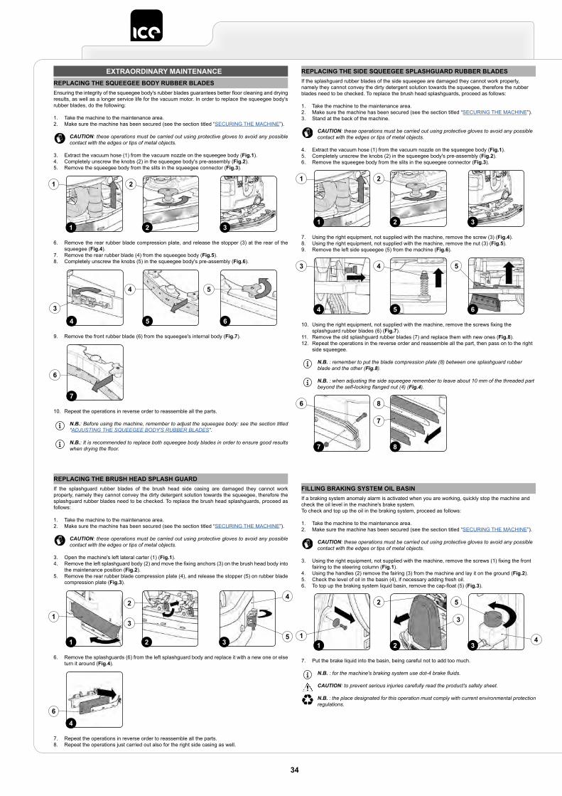
EXTRAORDINARY MAINTENANCEREPLACING THE SQUEEGEE BODY RUBBER BLADESEnsuring the integrity of the squeegee body's rubber blades guarantees better floor cleaning and drying results, as well as a longer service life for the vacuum motor. In order to replace the squeegee body's rubber blades, do the following:
1. Take the machine to the maintenance area.2. Make sure the machine has been secured (see the section titled “SECURING THE MACHINE”).
CAUTION: these operations must be carried out using protective gloves to avoid any possible contact with the edges or tips of metal objects.
3. Extract the vacuum hose (1) from the vacuum nozzle on the squeegee body (Fig.1).4. Completely unscrew the knobs (2) in the squeegee body's pre-assembly (Fig.2).5. Remove the squeegee body from the slits in the squeegee connector (Fig.3).
6. Remove the rear rubber blade compression plate, and release the stopper (3) at the rear of the squeegee (Fig.4).
7. Remove the rear rubber blade (4) from the squeegee body (Fig.5).8. Completely unscrew the knobs (5) in the squeegee body's pre-assembly (Fig.6).
9. Remove the front rubber blade (6) from the squeegee's internal body (Fig.7).
10. Repeat the operations in reverse order to reassemble all the parts.
N.B.: Before using the machine, remember to adjust the squeegee body: see the section titled “ADJUSTING THE SQUEEGEE BODY'S RUBBER BLADES”.
N.B.: It is recommended to replace both squeegee body blades in order to ensure good results when drying the floor.
2 31
1 2
4
3
65
4 5
7
6
REPLACING THE BRUSH HEAD SPLASH GUARDIf the splashguard rubber blades of the brush head side casing are damaged they cannot work properly, namely they cannot convey the dirty detergent solution towards the squeegee, therefore the splashguard rubber blades need to be checked. To replace the brush head splashguards, proceed as follows:
1. Take the machine to the maintenance area.2. Make sure the machine has been secured (see the section titled “SECURING THE MACHINE”).
CAUTION: these operations must be carried out using protective gloves to avoid any possible contact with the edges or tips of metal objects.
3. Open the machine's left lateral carter (1) (Fig.1).4. Remove the left splashguard body (2) and move the fixing anchors (3) on the brush head body into
the maintenance position (Fig.2).5. Remove the rear rubber blade compression plate (4), and release the stopper (5) on rubber blade
compression plate (Fig.3).
6. Remove the splashguards (6) from the left splashguard body and replace it with a new one or else turn it around (Fig.4).
7. Repeat the operations in reverse order to reassemble all the parts.8. Repeat the operations just carried out also for the right side casing as well.
31 2
1
2
5
4
3
4
6
FILLING BRAKING SYSTEM OIL BASINIf a braking system anomaly alarm is activated when you are working, quickly stop the machine and check the oil level in the machine's brake system.To check and top up the oil in the braking system, proceed as follows:
1. Take the machine to the maintenance area.2. Make sure the machine has been secured (see the section titled “SECURING THE MACHINE”).
CAUTION: these operations must be carried out using protective gloves to avoid any possible contact with the edges or tips of metal objects.
3. Using the right equipment, not supplied with the machine, remove the screws (1) fixing the front fairing to the steering column (Fig.1).
4. Using the handles (2) remove the fairing (3) from the machine and lay it on the ground (Fig.2).5. Check the level of oil in the basin (4), if necessary adding fresh oil.6. To top up the braking system liquid basin, remove the cap-float (5) (Fig.3).
7. Put the brake liquid into the basin, being careful not to add too much.
N.B. : for the machine's braking system use dot-4 brake fluids.
CAUTION: to prevent serious injuries carefully read the product's safety sheet.
N.B. : the place designated for this operation must comply with current environmental protection regulations.
2 311
2
3
4
5
REPLACING THE SIDE SQUEEGEE SPLASHGUARD RUBBER BLADESIf the splashguard rubber blades of the side squeegee are damaged they cannot work properly, namely they cannot convey the dirty detergent solution towards the squeegee, therefore the rubber blades need to be checked. To replace the brush head splashguards, proceed as follows:
1. Take the machine to the maintenance area.2. Make sure the machine has been secured (see the section titled “SECURING THE MACHINE”).3. Stand at the back of the machine.
CAUTION: these operations must be carried out using protective gloves to avoid any possible contact with the edges or tips of metal objects.
4. Extract the vacuum hose (1) from the vacuum nozzle on the squeegee body (Fig.1).5. Completely unscrew the knobs (2) in the squeegee body's pre-assembly (Fig.2).6. Remove the squeegee body from the slits in the squeegee connector (Fig.3).
7. Using the right equipment, not supplied with the machine, remove the screw (3) (Fig.4).8. Using the right equipment, not supplied with the machine, remove the nut (3) (Fig.5).9. Remove the left side squeegee (5) from the machine (Fig.6).
10. Using the right equipment, not supplied with the machine, remove the screws fixing the splashguard rubber blades (6) (Fig.7).
11. Remove the old splashguard rubber blades (7) and replace them with new ones (Fig.8).12. Repeat the operations in the reverse order and reassemble all the part, then pass on to the right
side squeegee.
N.B. : remember to put the blade compression plate (8) between one splashguard rubber blade and the other (Fig.8).
N.B. : when adjusting the side squeegee remember to leave about 10 mm of the threaded part beyond the self-locking flanged nut (4) (Fig.4).
2 31
1 2
5 64
3 4 5
87
6 8
7
34
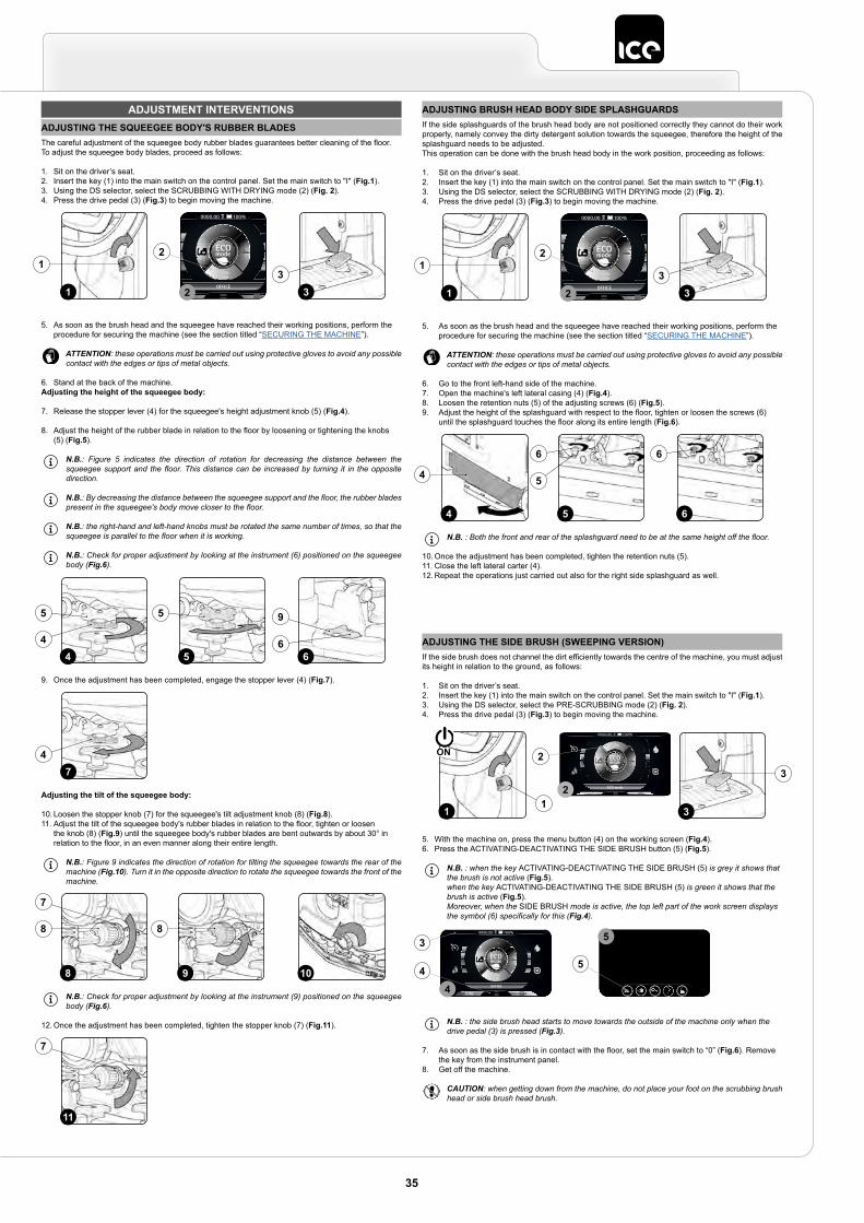
ADJUSTMENT INTERVENTIONSADJUSTING THE SQUEEGEE BODY'S RUBBER BLADESThe careful adjustment of the squeegee body rubber blades guarantees better cleaning of the floor.To adjust the squeegee body blades, proceed as follows:
1. Sit on the driver’s seat.2. Insert the key (1) into the main switch on the control panel. Set the main switch to "I" (Fig.1).3. Using the DS selector, select the SCRUBBING WITH DRYING mode (2) (Fig. 2).4. Press the drive pedal (3) (Fig.3) to begin moving the machine.
5. As soon as the brush head and the squeegee have reached their working positions, perform the procedure for securing the machine (see the section titled “SECURING THE MACHINE”).
ATTENTION: these operations must be carried out using protective gloves to avoid any possible contact with the edges or tips of metal objects.
6. Stand at the back of the machine.Adjusting the height of the squeegee body:
7. Release the stopper lever (4) for the squeegee's height adjustment knob (5) (Fig.4).
8. Adjust the height of the rubber blade in relation to the floor by loosening or tightening the knobs (5) (Fig.5).
N.B.: Figure 5 indicates the direction of rotation for decreasing the distance between the squeegee support and the floor. This distance can be increased by turning it in the opposite direction.
N.B.: By decreasing the distance between the squeegee support and the floor, the rubber blades present in the squeegee's body move closer to the floor.
N.B.: the right-hand and left-hand knobs must be rotated the same number of times, so that the squeegee is parallel to the floor when it is working.
N.B.: Check for proper adjustment by looking at the instrument (6) positioned on the squeegee body (Fig.6).
9. Once the adjustment has been completed, engage the stopper lever (4) (Fig.7).
Adjusting the tilt of the squeegee body:
10. Loosen the stopper knob (7) for the squeegee's tilt adjustment knob (8) (Fig.8).11. Adjust the tilt of the squeegee body's rubber blades in relation to the floor, tighten or loosen
the knob (8) (Fig.9) until the squeegee body's rubber blades are bent outwards by about 30° in relation to the floor, in an even manner along their entire length.
N.B.: Figure 9 indicates the direction of rotation for tilting the squeegee towards the rear of the machine (Fig.10). Turn it in the opposite direction to rotate the squeegee towards the front of the machine.
N.B.: Check for proper adjustment by looking at the instrument (9) positioned on the squeegee body (Fig.6).
12. Once the adjustment has been completed, tighten the stopper knob (7) (Fig.11).
31
13
OFFICE
0000.00 100%
2
2
5 644
5 5
6
9
74
9 108
8 8
7
11
7
ADJUSTING BRUSH HEAD BODY SIDE SPLASHGUARDSIf the side splashguards of the brush head body are not positioned correctly they cannot do their work properly, namely convey the dirty detergent solution towards the squeegee, therefore the height of the splashguard needs to be adjusted.This operation can be done with the brush head body in the work position, proceeding as follows:
1. Sit on the driver’s seat.2. Insert the key (1) into the main switch on the control panel. Set the main switch to "I" (Fig.1).3. Using the DS selector, select the SCRUBBING WITH DRYING mode (2) (Fig. 2).4. Press the drive pedal (3) (Fig.3) to begin moving the machine.
5. As soon as the brush head and the squeegee have reached their working positions, perform the procedure for securing the machine (see the section titled “SECURING THE MACHINE”).
ATTENTION: these operations must be carried out using protective gloves to avoid any possible contact with the edges or tips of metal objects.
6. Go to the front left-hand side of the machine.7. Open the machine's left lateral casing (4) (Fig.4).8. Loosen the retention nuts (5) of the adjusting screws (6) (Fig.5).9. Adjust the height of the splashguard with respect to the floor, tighten or loosen the screws (6)
until the splashguard touches the floor along its entire length (Fig.6).
N.B. : Both the front and rear of the splashguard need to be at the same height off the floor.
10. Once the adjustment has been completed, tighten the retention nuts (5).11. Close the left lateral carter (4).12. Repeat the operations just carried out also for the right side splashguard as well.
31
13
OFFICE
0000.00 100%
2
2
64 5
4
6
5
6
ADJUSTING THE SIDE BRUSH (SWEEPING VERSION)If the side brush does not channel the dirt efficiently towards the centre of the machine, you must adjust its height in relation to the ground, as follows:
1. Sit on the driver’s seat.2. Insert the key (1) into the main switch on the control panel. Set the main switch to "I" (Fig.1).3. Using the DS selector, select the PRE-SCRUBBING mode (2) (Fig. 2).4. Press the drive pedal (3) (Fig.3) to begin moving the machine.
5. With the machine on, press the menu button (4) on the working screen (Fig.4).6. Press the ACTIVATING-DEACTIVATING THE SIDE BRUSH button (5) (Fig.5).
N.B. : when the key ACTIVATING-DEACTIVATING THE SIDE BRUSH (5) is grey it shows that the brush is not active (Fig.5).when the key ACTIVATING-DEACTIVATING THE SIDE BRUSH (5) is green it shows that the brush is active (Fig.5).Moreover, when the SIDE BRUSH mode is active, the top left part of the work screen displays the symbol (6) specifically for this (Fig.4).
N.B. : the side brush head starts to move towards the outside of the machine only when the drive pedal (3) is pressed (Fig.3).
7. As soon as the side brush is in contact with the floor, set the main switch to “0” (Fig.6). Remove the key from the instrument panel.
8. Get off the machine.
CAUTION: when getting down from the machine, do not place your foot on the scrubbing brush head or side brush head brush.
1
ECO mode
0000.00 100%
21
2ON
3
3
OFFICE
0000.00 100% 0000.00 100%
ECO mode4
5
54
3
35
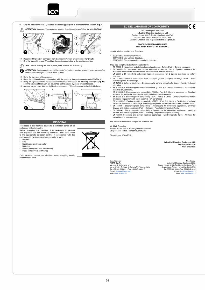
DISPOSALTo dispose of the machine, take it to a demolition centre or an authorised collection centre.Before scrapping the machine, it is necessary to remove and separate out the following materials, then send them to the appropriate collection centres in accordance with the environmental hygiene regulations currently in force:• Brushes• Felt• Electric and electronic parts*• Batteries• Plastic parts (tanks and handlebars)• Metal parts (levers and frame)
(*) In particular, contact your distributor when scrapping electric and electronic parts.
EC DECLARATION OF CONFORMITYThe undersigned company:
Industrial Cleaning Equipment Ltd.Sauber House, Unit 3, Rushington Business Park
Chapel Lane, Totton, Hampshire, SO40 9AHDeclares under its sole responsibility that the products
FLOOR SCRUBBING MACHINESmod. MTECH R 90 D - MTECH R 90 C
comply with the provisions of Directives:
• 2006/42/EC: Machinery Directive.• 2014/35/EC: Low Voltage Directive.• 2014/30/EC: Electromagnetic compatibility directive.
They also comply with the following standards:• EN 60335-1: Household and similar electrical appliances - Safety. Part 1: Generic standards.• EN 60335-2-72: Household and similar electrical appliances. Part 2: Specific standards for
automatic machines for floor treatment for commercial and industrial use.• EN 60335-2-29: Household and similar electrical appliances. Part 2: Special standards for battery
chargers.• EN 12100-1: Safety of Machinery - Basic concepts, general principles for design - Part 1: Basic
terminology and methodology.• EN 12100-2: Safety of Machinery - Basic concepts, general principles for design - Part 2: Technical
principles.• EN 61000-6-2: Electromagnetic compatibility (EMC) - Part 6-2: Generic standards – Immunity for
industrial environments.• EN 61000-6-3: Electromagnetic compatibility (EMC) - Part 6-3: Generic standards — Standard
emission for residential, commercial and light-industrial environments.• EN 61000-3-2: Electromagnetic compatibility (EMC) - Part 3-2: Limits – Limits for harmonic current
emissions (Equipment with input current ≤ 16 A per phase).• EN 61000-3-3: Electromagnetic compatibility (EMC) - Part 3-3: Limits – Restriction of voltage
variations and flicker in low voltage power supply systems for devices with a rated current ≤ 16 A.• EN 55014-1: Electromagnetic compatibility - Regulations for household appliances, electrical
devices and similar equipment. Part 1: Emission - Regulation for product family.• EN 55014-2: Electromagnetic compatibility - Regulations for household appliances, electrical
devices and similar equipment. Part 2: Immunity - Regulation for product family.• EN 62233: Household and similar electrical appliances - Electromagnetic fields - Methods for
evaluation and measurement.
The person authorised to compile the technical file:
Mr. Mark BresnihanSauber House, Unit 3, Rushington Business ParkChapel Lane, Totton, Hampshire, SO40 9AH
Chapel Lane, 17/09/2018
Industrial Cleaning Equipment Ltd.Legal representative
Mark Bresnihan
9. Grip the back of the seat (7) and turn the seat support plate to its maintenance position (Fig.7).
ATTENTION: to prevent the seat from rotating, insert the retainer (8) into the slot (9) (Fig.8).
10. Disconnect the battery connector from the machine's main system connector (Fig.9).11. Grip the back of the seat (7) and turn the seat support plate to the working position.
N.B. : before rotating the seat support plate, remove the retainer (8).
ATTENTION: these operations must be carried out using protective gloves to avoid any possible contact with the edges or tips of metal objects.
12. Go to the right side of the machine.13. Using the right equipment, not supplied with the machine, loosen the counter nut (10) (Fig.10).14. Using the right equipment, not supplied with the machine, loosen the adjusting screw (11) (Fig.11),
until the bristles of the brush are squashed on the ground by about two centimetres.15. As soon as you have finished, tighten the counter nut (10) and move on to the left side brush.
8
8
9
7 76 1
OFF
11
11
9 10
10
Manufacturer:FIMAP S.p.A.Via Invalidi del Lavoro, n°1c.a.p. 37059 - S. Maria di Zevio (VR) - Verona - ItaliaTel. +39 045 6060411 - Fax. +39 045 6060417E-mail: [email protected]: www.fimap.com
Mandatory:Industrial Cleaning Equipment Ltd.
Sauber House, Unit 3, Rushington Business ParkChapel Lane, Totton, Hampshire, SO40 9AH
Tel. 0800 389 3869 - Fax. 023 8042 8318E-mail: [email protected]
Web: www.ice-clean.com
36

TROUBLESHOOTINGThis chapter lists the most common problems linked with the use of the machine. If you are unable to resolve the problems with the information given here, please contact your nearest assistance centre.
PROBLEM POSSIBLE CAUSE SOLUTION
THE MACHINE DOES NOT START
The main switch is set to “0”. Make sure that the main switch is set to "I".
Check whether there are any alarm messages on the control display. Stop the machine immediately, and contact a specialised service centre.
Make sure that the batteries are correctly connected to each other and that the battery connector is connected to the electrical system connector.
Make sure that the batteries are properly connected inside the machine (see the section titled INSERTING THE BATTERIES INTO THE MACHINE”).
Check the charge level of the batteries. If the battery charge level is critical, perform a complete recharge cycle (see paragraph CHARGING THE BATTERIES”).
THE BATTERIES ARE NOT CHARGED CORRECTLY (VERSIONS WITHOUT AN ON BOARD BATTERY CHARGER)
The connector of the battery charger cable is not properly inserted in the battery connector. Connect the battery charger cable connector to the battery connector again.
The plug on the battery charger's power cable is not correctly inserted into the electrical outlet. Check that the battery charger power supply cable plug is connected to the mains socket.
The characteristics of the mains power supply do not correspond to those required by the battery charger. Check that the characteristics in the battery charger plate are the same as those of the mains supply.
The LEDs of the battery charger blink repeatedly. Referring to the battery charger use and maintenance manual, check the meaning of the flashing signals that the battery charger emits dung the battery recharge stage.
THE BATTERIES ARE NOT CHARGED CORRECTLY (VERSIONS WITH AN ON BOARD BATTERY CHARGER)
The plug on the battery charger's cable is not correctly inserted into the socket on the battery charger itself. Reconnect the battery charger's power cable.
The plug on the battery charger's power cable is not correctly inserted into the electrical outlet. Check that the battery charger power supply cable plug is connected to the mains socket.
The characteristics of the mains power supply do not correspond to those required by the battery charger. Check that the characteristics in the battery charger plate are the same as those of the mains supply.
The LEDs of the battery charger blink repeatedly. Referring to the battery charger use and maintenance manual, check the meaning of the flashing signals that the battery charger emits dung the battery recharge stage.
THE MACHINE HAS A VERY LOW WORK AUTONOMY
Check the battery charge level, check the symbol on the command display.
If the battery charge level is critical, perform a complete recharge cycle (see paragraph CHARGING THE BATTERIES”).
THE MACHINE DOES NOT MOVE
The machine does not start. Read the section “THE MACHINE DOES NOT START”.
There is an issue on the drive pedal. Contact your nearest service centre.
INSUFFICIENT DETERGENT SOLUTION ON THE BRUSHES
The quantity of detergent solution in the water system is not sufficient for the work to be carried out.
Check that the amount of detergent solution present in the machine's water system is sufficient for the work to be carried out.
Detergent solution filter obstructed. Check the detergent solution filter isn't obstructed. If it is, clean it (see “CLEANING THE WATER SYSTEM FILTER”).
THE MACHINE DOES NOT CLEAN CORRECTLY
The machine does not start. Read the section “THE MACHINE DOES NOT START”.
Not enough detergent solution comes out. Read the section “INSUFFICIENT DETERGENT SOLUTION ON THE BRUSHES”.
The brushes have not been inserted correctly in the machine. Check that the brushes have been inserted correctly (read the paragraph “FITTING BRUSH”).
The type of brush used is not suitable for the dirt to be cleaned. Check that the brushes on the machine are adequate for the work to be carried out.
The brush bristles are excessively worn. Check the condition of the brush, and replace it if necessary (see “FITTING THE BRUSH”).
THE SQUEEGEE DOES NOT DRY PERFECTLY
The vacuum unit is obstructed.
Make sure the squeegee is free of obstructions (read “CLEANING THE SQUEEGEE BODY”).
Make sure the squeegee is free of obstructions (read “CLEANING THE SQUEEGEE BODY” and “CLEANING THE VACUUM TUBE”).
Make sure the vacuum cap filter is free of obstructions (see “CLEANING THE RECOVERY TANK FILTERS”).
Make sure the vacuum motor filter is free of obstructions (see “CLEANING THE RECOVERY TANK FILTERS”).
The cap on the recovery tank drainage tube is not properly positioned. Check that the cap on the recovery tank drainage tube is positioned properly.
The recovery tank lid is not positioned correctly. Check that the recovery tank lid is properly positioned on the machine.
EXCESSIVE FOAM PRODUCTION
The detergent being used is not suitable. Check that a low foam detergent has been used. If necessary, add a small quantity of anti-foam liquid to the recovery tank.
The floor is not very dirty. Dilute the detergent more.
THE MACHINE DOES NOT VACUUM CORRECTLY
The recovery tank is full. Empty the recovery tank (read “EMPTYING THE RECOVERY TANK”).
The vacuum device is obstructed Read the section "THE SQUEEGEE DOES NOT DRY PERFECTLY".
37
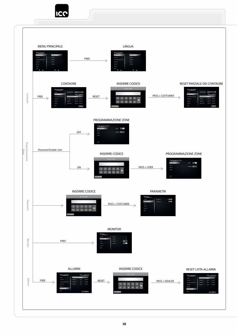
38
Menu principale
Lingua
Contaore
Programmazione Zone
Parametri
Monitor
Allarmi
Esci
Italiano
English
Spanish
French
German
Menu principale
Lingua
Contaore
Programmazione Zone
Parametri
Monitor
Allarmi
Esci
Italiano
English
Spanish
French
German
Reset
Menu principale
Lingua
Contaore
Programmazione Zone
Parametri
Monitor
Allarmi
Esci
VISUALIZZATO
TOTALE PARZIALE
Chiave 0000.00 0000.00
Trazione 0000.00 0000.00
Spazzole 0000.00 0000.00
Aspirazione 0000.00 0000.00
Chiave
Reset
Menu principale
Lingua
Contaore
Programmazione Zone
Parametri
Monitor
Allarmi
Esci
VISUALIZZATO
TOTALE PARZIALE
Chiave 0000.00 0000.00
Trazione 0000.00 0000.00
Spazzole 0000.00 0000.00
Aspirazione 0000.00 0000.00
Chiave
Enter
Inserire codice
Enter
Inserire codice
Enter
Inserire codice
OFF
Programmazione Zone
Zone 1
Zone 2
Zone 3
Zone 4
Esci
ZONE
MANUAL
ON
OFF
Programmazione Zone
Zone 1
Zone 2
Zone 3
Zone 4
Esci
ZONE
MANUAL
ON
Monitor
General
Brush
Pump
Vacuum
Traction
Esci
Valore 1 100
Valore 2 23.5
Valore 3
Valore 4
A
V
OFF
ON
Parametri
General
Brush
Pump
Vacuum
Traction
Esci
Parametro 1 100
Parametro 2 List
...
A
? Reset
Menu principale COUNT
Lingua
Contaore
Programmazione Zone
Parametri
Monitor
Allarmi
Esci
Allarme 1 000 0000.00
Allarme 2 000 0000.00
Allarme 3 000 0000.00
Allarme 4 000 0000.00
HOUR METER
? Reset
Menu principale COUNT
Lingua
Contaore
Programmazione Zone
Parametri
Monitor
Allarmi
Esci
Allarme 1 000 0000.00
Allarme 2 000 0000.00
Allarme 3 000 0000.00
Allarme 4 000 0000.00
HOUR METER
Enter
Inserire codice
MENU PRINCIPALE
FREE
PASS ≥ USER
PASS ≥ COSTUMER
PASS ≥ COSTUMER
PASS ≥ DEALER
FREE
Password Enable: User
FREE
RESET
RESET
OFF
ON
FREE
CONTAORE
PARAMETRI
MONITOR
ALLARMI RESET LISTA ALLARMI
INSERIRE CODICE
INSERIRE CODICE
INSERIRE CODICE
INSERIRE CODICE RESET PARZIALE DEI CONTAORE
PROGRAMMAZIONE ZONE
PROGRAMMAZIONE ZONE
LINGUA
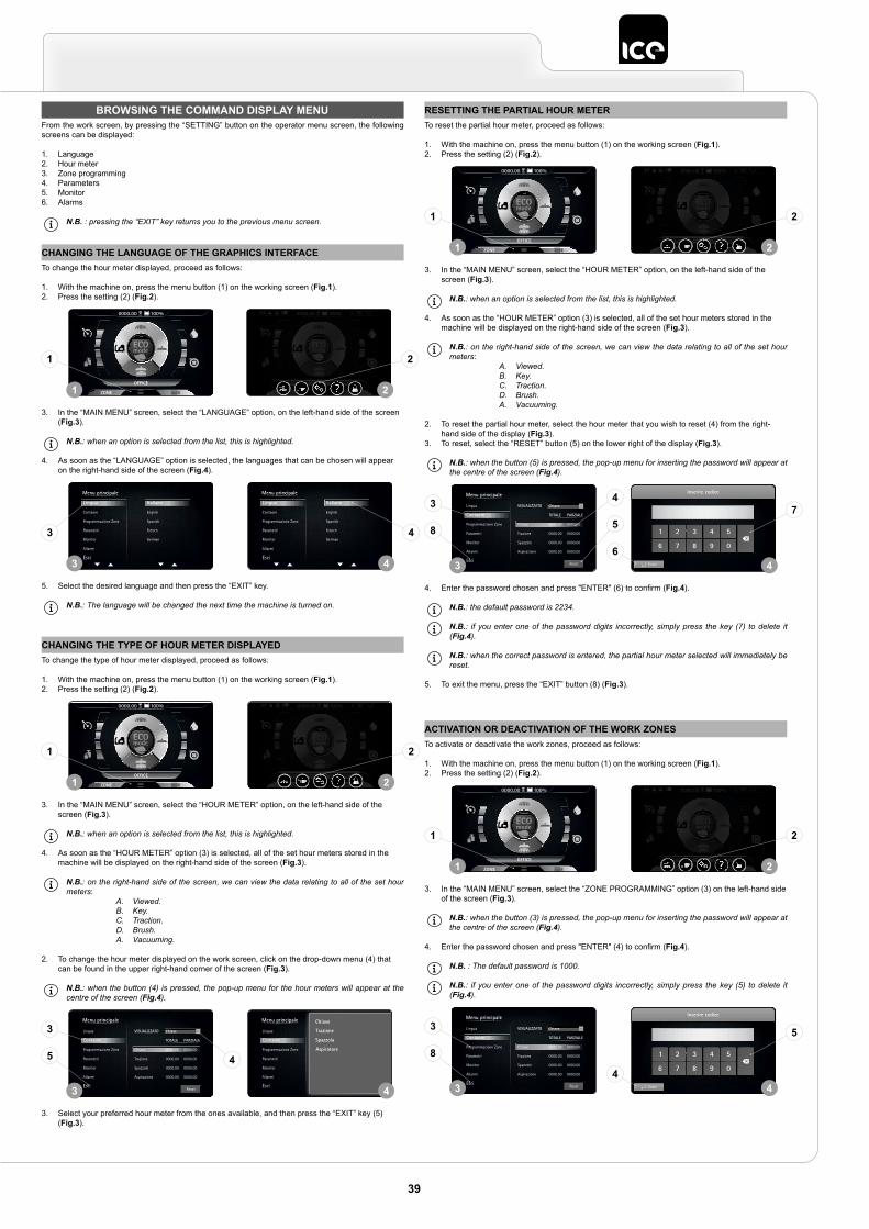
BROWSING THE COMMAND DISPLAY MENUFrom the work screen, by pressing the “SETTING” button on the operator menu screen, the following screens can be displayed:
1. Language2. Hour meter3. Zone programming4. Parameters5. Monitor6. Alarms
N.B. : pressing the “EXIT” key returns you to the previous menu screen.
CHANGING THE LANGUAGE OF THE GRAPHICS INTERFACETo change the hour meter displayed, proceed as follows:
1. With the machine on, press the menu button (1) on the working screen (Fig.1).2. Press the setting (2) (Fig.2).
3. In the “MAIN MENU” screen, select the “LANGUAGE” option, on the left-hand side of the screen (Fig.3).
N.B.: when an option is selected from the list, this is highlighted.
4. As soon as the “LANGUAGE” option is selected, the languages that can be chosen will appear on the right-hand side of the screen (Fig.4).
5. Select the desired language and then press the “EXIT” key.
N.B.: The language will be changed the next time the machine is turned on.
OFFICE
0000.00 100% 0000.00 100%
ECO mode
1 2
1 2
Menu principale
Lingua
Contaore
Programmazione Zone
Parametri
Monitor
Allarmi
Esci
Italiano
English
Spanish
French
German
Menu principale
Lingua
Contaore
Programmazione Zone
Parametri
Monitor
Allarmi
Esci
Italiano
English
Spanish
French
German
3 4
3 4
CHANGING THE TYPE OF HOUR METER DISPLAYEDTo change the type of hour meter displayed, proceed as follows:
1. With the machine on, press the menu button (1) on the working screen (Fig.1).2. Press the setting (2) (Fig.2).
3. In the “MAIN MENU” screen, select the “HOUR METER” option, on the left-hand side of the screen (Fig.3).
N.B.: when an option is selected from the list, this is highlighted.
4. As soon as the “HOUR METER” option (3) is selected, all of the set hour meters stored in the machine will be displayed on the right-hand side of the screen (Fig.3).
N.B.: on the right-hand side of the screen, we can view the data relating to all of the set hour meters:
A. Viewed.B. Key.C. Traction.D. Brush.A. Vacuuming.
2. To change the hour meter displayed on the work screen, click on the drop-down menu (4) that can be found in the upper right-hand corner of the screen (Fig.3).
N.B.: when the button (4) is pressed, the pop-up menu for the hour meters will appear at the centre of the screen (Fig.4).
3. Select your preferred hour meter from the ones available, and then press the “EXIT” key (5) (Fig.3).
OFFICE
0000.00 100% 0000.00 100%
ECO mode
1 2
1 2
Reset
Menu principale
Lingua
Contaore
Programmazione Zone
Parametri
Monitor
Allarmi
Esci
VISUALIZZATO
TOTALE PARZIALE
Chiave 0000.00 0000.00
Trazione 0000.00 0000.00
Spazzole 0000.00 0000.00
Aspirazione 0000.00 0000.00
Chiave
Reset
Menu principale
Lingua
Contaore
Programmazione Zone
Parametri
Monitor
Allarmi
Esci
VISUALIZZATO
TOTALE PARZIALE
Chiave 0000.00 0000.00
Trazione 0000.00 0000.00
Spazzole 0000.00 0000.00
Aspirazione 0000.00 0000.00
Chiave
3 4
3
5 4
RESETTING THE PARTIAL HOUR METERTo reset the partial hour meter, proceed as follows:
1. With the machine on, press the menu button (1) on the working screen (Fig.1).2. Press the setting (2) (Fig.2).
3. In the “MAIN MENU” screen, select the “HOUR METER” option, on the left-hand side of the screen (Fig.3).
N.B.: when an option is selected from the list, this is highlighted.
4. As soon as the “HOUR METER” option (3) is selected, all of the set hour meters stored in the machine will be displayed on the right-hand side of the screen (Fig.3).
N.B.: on the right-hand side of the screen, we can view the data relating to all of the set hour meters:
A. Viewed.B. Key.C. Traction.D. Brush.A. Vacuuming.
2. To reset the partial hour meter, select the hour meter that you wish to reset (4) from the right-hand side of the display (Fig.3).
3. To reset, select the “RESET” button (5) on the lower right of the display (Fig.3).
N.B.: when the button (5) is pressed, the pop-up menu for inserting the password will appear at the centre of the screen (Fig.4).
4. Enter the password chosen and press "ENTER" (6) to confirm (Fig.4).
N.B.: the default password is 2234.
N.B.: if you enter one of the password digits incorrectly, simply press the key (7) to delete it (Fig.4).
N.B.: when the correct password is entered, the partial hour meter selected will immediately be reset.
5. To exit the menu, press the “EXIT” button (8) (Fig.3).
OFFICE
0000.00 100% 0000.00 100%
ECO mode
1 2
1 2
Reset
Menu principale
Lingua
Contaore
Programmazione Zone
Parametri
Monitor
Allarmi
Esci
VISUALIZZATO
TOTALE PARZIALE
Chiave 0000.00 0000.00
Trazione 0000.00 0000.00
Spazzole 0000.00 0000.00
Aspirazione 0000.00 0000.00
Chiave
Enter
Inserire codice
3 4
3
8 5
4
6
7
ACTIVATION OR DEACTIVATION OF THE WORK ZONESTo activate or deactivate the work zones, proceed as follows:
1. With the machine on, press the menu button (1) on the working screen (Fig.1).2. Press the setting (2) (Fig.2).
3. In the “MAIN MENU” screen, select the “ZONE PROGRAMMING” option (3) on the left-hand side of the screen (Fig.3).
N.B.: when the button (3) is pressed, the pop-up menu for inserting the password will appear at the centre of the screen (Fig.4).
4. Enter the password chosen and press "ENTER" (4) to confirm (Fig.4).
N.B. : The default password is 1000.
N.B.: if you enter one of the password digits incorrectly, simply press the key (5) to delete it (Fig.4).
OFFICE
0000.00 100% 0000.00 100%
ECO mode
1 2
1 2
Reset
Menu principale
Lingua
Contaore
Programmazione Zone
Parametri
Monitor
Allarmi
Esci
VISUALIZZATO
TOTALE PARZIALE
Chiave 0000.00 0000.00
Trazione 0000.00 0000.00
Spazzole 0000.00 0000.00
Aspirazione 0000.00 0000.00
Chiave
Enter
Inserire codice
3 4
3
8
4
5
39
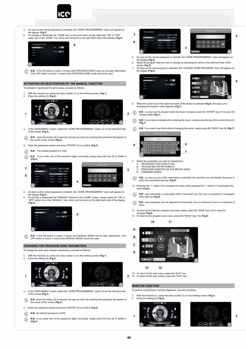
5. As soon as the correct password is inserted, the “ZONE PROGRAMMING” menu will appear on the display (Fig.5).
6. To activate or deactivate the “ZONE” key on the work menu, simply select the “ON” or “OFF” option (6) on the “ZONE” row, which can be found on the right-hand side of the display (Fig.5).
N.B. : if the ON button is active, it means that PROGRAM ZONE mode can be used. Meanwhile, if the OFF button is active, it means that PROGRAM ZONE mode cannot be used.
OFF
Programmazione Zone
Zone 1
Zone 2
Zone 3
Zone 4
Esci
ZONE
MANUAL
ON
5
6
ACTIVATION OR DEACTIVATION OF THE MANUAL FUNCTIONTo activate or deactivate the work zones, proceed as follows:
1. With the machine on, press the menu button (1) on the working screen (Fig.1).2. Press the setting (2) (Fig.2).
3. In the “MAIN MENU” screen, select the “ZONE PROGRAMMING” option (3) on the left-hand side of the screen (Fig.3).
N.B. : when the button (3) is pressed, the pop-up menu for inserting the password will appear at the centre of the screen (Fig.4).
4. Enter the password chosen and press "ENTER" (4) to confirm (Fig.4).
N.B. : The default password is 1000.
N.B. : if you enter one of the password digits incorrectly, simply press the key (5) to delete it (Fig.4).
5. As soon as the correct password is inserted, the “ZONE PROGRAMMING” menu will appear on the display (Fig.5).
6. To activate or deactivate the "MANUAL" function in the “ZONE” screen, simply select the “ON” or “OFF” option (6) on the “MANUAL” row, which can be found on the right-hand side of the display (Fig.5).
N.B. : if the ON button is active, it means that MANUAL MODE can be used. Meanwhile, if the OFF button is active, it means that MANUAL MODE cannot be used.
OFFICE
0000.00 100% 0000.00 100%
ECO mode
1 2
1 2
Reset
Menu principale
Lingua
Contaore
Programmazione Zone
Parametri
Monitor
Allarmi
Esci
VISUALIZZATO
TOTALE PARZIALE
Chiave 0000.00 0000.00
Trazione 0000.00 0000.00
Spazzole 0000.00 0000.00
Aspirazione 0000.00 0000.00
Chiave
Enter
Inserire codice
3 4
3
8
4
5
OFF
Programmazione Zone
Zone 1
Zone 2
Zone 3
Zone 4
Esci
ZONE
MANUAL
ON
5
6
MONITOR FUNCTIONTo perform a preliminary machine diagnosis, proceed as follows:
1. With the machine on, press the menu button (1) on the working screen (Fig.1).2. Press the setting (2) (Fig.2).
OFFICE
0000.00 100% 0000.00 100%
ECO mode
1 2
1 2
CHANGING THE PROGRAM ZONE PARAMETERSTo change the work zone program parameters, proceed as follows:
1. With the machine on, press the menu button (1) on the working screen (Fig.1).2. Press the setting (2) (Fig.2).
3. In the “MAIN MENU” screen, select the “ZONE PROGRAMMING” option (3) on the left-hand side of the screen (Fig.3).
N.B.: when the button (3) is pressed, the pop-up menu for inserting the password will appear at the centre of the screen (Fig.4).
4. Enter the password chosen and press "ENTER" (4) to confirm (Fig.4).
N.B.: the default password is 2234.
N.B.: if you enter one of the password digits incorrectly, simply press the key (5) to delete it (Fig.4).
OFFICE
0000.00 100% 0000.00 100%
ECO mode
1 2
1 2
5. As soon as the correct password is inserted, the “ZONE PROGRAMMING” menu will appear on the display (Fig.5).
6. Select the program that you wish to change by selecting the name on the left-hand side of the screen (Fig.5).
7. As soon as the zone program is selected, the “CHANGE ZONE PROGRAM” menu will appear on the display (Fig.6).
8. When the button (6) on the right-hand side of the screen is pressed (Fig.6), the pop-up for changing the program name appears (Fig.7).
N.B. : as soon as the program name has been changed, press the “ENTER” key (7) to save the change made (Fig.7).
N.B.: if you make a mistake when entering the name, simply press the key (8) to correct the error (Fig.7).
N.B.: if you want to go back without changing the name, simply press the “BACK” key (9) (Fig.7).
9. Select the parameter you wish to change from:A. DETERGENT SOLUTION FLOWB. VACUUM MOTOR EFFICIENCY;C. PRESSURE EXERTED ON THE BRUSH HEAD;D. FORWARD SPEED.
N.B.: as soon as one of the parameters is selected, the machine icon will display the group to which this parameter belongs (Fig.8).
10. Pressing the “+” button (10) increases the value, while pressing the “-” button (11) decreases the value (Fig.8).
N.B.: each parameter is associated with a horizontal row; this row is composed of rectangles which light up (Fig.8).
N.B.: each parameter can be adjusted to three levels, from a minimum of one to a maximum of three.
11. As soon as the desired changes have been made, press the “SAVE” key (12) to save the changes (Fig.8).
12. To return to the program zone menu, press the “BACK” key (13) (Fig.8).
13. To return to the main menu, press the “EXIT” key.14. To return to the work screen, press the “EXIT” key.
Reset
Menu principale
Lingua
Contaore
Programmazione Zone
Parametri
Monitor
Allarmi
Esci
VISUALIZZATO
TOTALE PARZIALE
Chiave 0000.00 0000.00
Trazione 0000.00 0000.00
Spazzole 0000.00 0000.00
Aspirazione 0000.00 0000.00
Chiave
Enter
Inserire codice
3 4
3
8
4
5
OFF
Programmazione Zone
Zone 1
Zone 2
Zone 3
Zone 4
Esci
ZONE
MANUAL
ON
5 6
6
Modifica nome zona
77
89
8
A
B
C
D
13
10 11
12
40
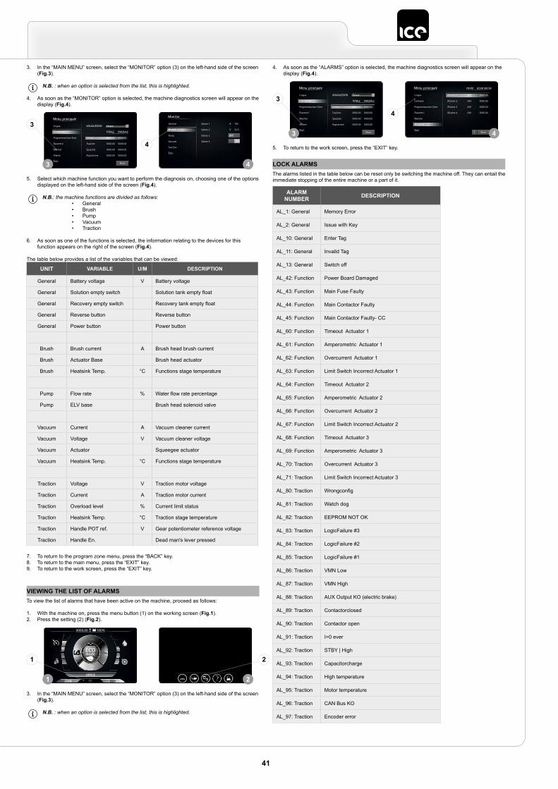
VIEWING THE LIST OF ALARMSTo view the list of alarms that have been active on the machine, proceed as follows:
1. With the machine on, press the menu button (1) on the working screen (Fig.1).2. Press the setting (2) (Fig.2).
3. In the “MAIN MENU” screen, select the “MONITOR” option (3) on the left-hand side of the screen (Fig.3).
N.B. : when an option is selected from the list, this is highlighted.
OFFICE
0000.00 100% 0000.00 100%
ECO mode
1 2
1 2
3. In the “MAIN MENU” screen, select the “MONITOR” option (3) on the left-hand side of the screen (Fig.3).
N.B. : when an option is selected from the list, this is highlighted.
4. As soon as the “MONITOR” option is selected, the machine diagnostics screen will appear on the display (Fig.4).
5. Select which machine function you want to perform the diagnosis on, choosing one of the options displayed on the left-hand side of the screen (Fig.4).
N.B.: the machine functions are divided as follows:• General• Brush• Pump• Vacuum• Traction
6. As soon as one of the functions is selected, the information relating to the devices for this function appears on the right of the screen (Fig.4).
The table below provides a list of the variables that can be viewed:
UNIT VARIABLE U/M DESCRIPTION
General Battery voltage V Battery voltage
General Solution empty switch Solution tank empty float
General Recovery empty switch Recovery tank empty float
General Reverse button Reverse button
General Power button Power button
Brush Brush current A Brush head brush current
Brush Actuator Base Brush head actuator
Brush Heatsink Temp. °C Functions stage temperature
Pump Flow rate % Water flow rate percentage
Pump ELV base Brush head solenoid valve
Vacuum Current A Vacuum cleaner current
Vacuum Voltage V Vacuum cleaner voltage
Vacuum Actuator Squeegee actuator
Vacuum Heatsink Temp. °C Functions stage temperature
Traction Voltage V Traction motor voltage
Traction Current A Traction motor current
Traction Overload level % Current limit status
Traction Heatsink Temp. °C Traction stage temperature
Traction Handle POT ref. V Gear potentiometer reference voltage
Traction Handle En. Dead man's lever pressed
7. To return to the program zone menu, press the “BACK” key.8. To return to the main menu, press the “EXIT” key.9. To return to the work screen, press the “EXIT” key.
Reset
Menu principale
Lingua
Contaore
Programmazione Zone
Parametri
Monitor
Allarmi
Esci
VISUALIZZATO
TOTALE PARZIALE
Chiave 0000.00 0000.00
Trazione 0000.00 0000.00
Spazzole 0000.00 0000.00
Aspirazione 0000.00 0000.00
Chiave
Monitor
General
Brush
Pump
Vacuum
Traction
Esci
Valore 1 100
Valore 2 23.5
Valore 3
Valore 4
A
V
OFF
ON
3 4
3
4
4. As soon as the “ALARMS” option is selected, the machine diagnostics screen will appear on the display (Fig.4).
5. To return to the work screen, press the “EXIT” key.
Reset
Menu principale
Lingua
Contaore
Programmazione Zone
Parametri
Monitor
Allarmi
Esci
VISUALIZZATO
TOTALE PARZIALE
Chiave 0000.00 0000.00
Trazione 0000.00 0000.00
Spazzole 0000.00 0000.00
Aspirazione 0000.00 0000.00
Chiave
? Reset
Menu principale COUNT
Lingua
Contaore
Programmazione Zone
Parametri
Monitor
Allarmi
Esci
Allarme 1 000 0000.00
Allarme 2 000 0000.00
Allarme 3 000 0000.00
Allarme 4 000 0000.00
HOUR METER
3 4
3
4
ALARM NUMBER DESCRIPTION
AL_1: General Memory Error
AL_2: General Issue with Key
AL_10: General Enter Tag
AL_11: General Invalid Tag
AL_13: General Switch off
AL_42: Function Power Board Damaged
AL_43: Function Main Fuse Faulty
AL_44: Function Main Contactor Faulty
AL_45: Function Main Contactor Faulty- CC
AL_60: Function Timeout Actuator 1
AL_61: Function Amperometric Actuator 1
AL_62: Function Overcurrent Actuator 1
AL_63: Function Limit Switch Incorrect Actuator 1
AL_64: Function Timeout Actuator 2
AL_65: Function Amperometric Actuator 2
AL_66: Function Overcurrent Actuator 2
AL_67: Function Limit Switch Incorrect Actuator 2
AL_68: Function Timeout Actuator 3
AL_69: Function Amperometric Actuator 3
AL_70: Traction Overcurrent Actuator 3
AL_71: Traction Limit Switch Incorrect Actuator 3
AL_80: Traction Wrongconfig
AL_81: Traction Watch dog
AL_82: Traction EEPROM NOT OK
AL_83: Traction LogicFailure #3
AL_84: Traction LogicFailure #2
AL_85: Traction LogicFailure #1
AL_86: Traction VMN Low
AL_87: Traction VMN High
AL_88: Traction AUX Output KO (electric brake)
AL_89: Traction Contactorclosed
AL_90: Traction Contactor open
AL_91: Traction I=0 ever
AL_92: Traction STBY | High
AL_93: Traction Capacitorcharge
AL_94: Traction High temperature
AL_95: Traction Motor temperature
AL_96: Traction CAN Bus KO
AL_97: Traction Encoder error
LOCK ALARMSThe alarms listed in the table below can be reset only be switching the machine off. They can entail the immediate stopping of the entire machine or a part of it.
41
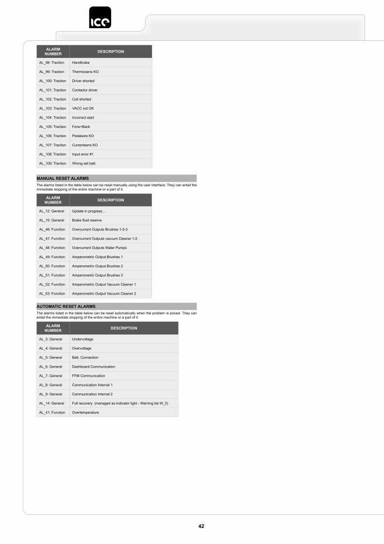
ALARM NUMBER DESCRIPTION
AL_98: Traction Handbrake
AL_99: Traction Thermicsens KO
AL_100: Traction Driver shorted
AL_101: Traction Contactor driver
AL_102: Traction Coil shorted
AL_103: Traction VACC not OK
AL_104: Traction Incorrect start
AL_105: Traction Forw+Back
AL_106: Traction Pedalwire KO
AL_107: Traction Currentsens KO
AL_108: Traction Input error #1
AL_109: Traction Wrong set batt.
MANUAL RESET ALARMSThe alarms listed in the table below can be reset manually using the user interface. They can entail the immediate stopping of the entire machine or a part of it.
AUTOMATIC RESET ALARMSThe alarms listed in the table below can be reset automatically when the problem is solved. They can entail the immediate stopping of the entire machine or a part of it.
ALARM NUMBER DESCRIPTION
AL_12: General Update in progress…
AL_15: General Brake fluid reserve
AL_46: Function Overcurrent Outputs Brushes 1-2-3
AL_47: Function Overcurrent Outputs vacuum Cleaner 1-2
AL_48: Function Overcurrent Outputs Water Pumps
AL_49: Function Amperometric Output Brushes 1
AL_50: Function Amperometric Output Brushes 2
AL_51: Function Amperometric Output Brushes 3
AL_52: Function Amperometric Output Vacuum Cleaner 1
AL_53: Function Amperometric Output Vacuum Cleaner 2
ALARM NUMBER DESCRIPTION
AL_3: General Undervoltage
AL_4: General Overvoltage
AL_5: General Batt. Connection
AL_6: General Dashboard Communication
AL_7: General FFM Communication
AL_8: General Communication Internal 1
AL_9: General Communication Internal 2
AL_14: General Full recovery (managed as indicator light - Warning list W_2)
AL_41: Function Overtemperature
42


Industrial Cleaning Equipment Ltd.Sauber House, Unit 3, Rushington Business Park - Chapel Lane, Totton, Hampshire, SO40 9AH
Service 0800 389 3869 - Facsmile 023 8042 8318 - Email [email protected]