mts sensors technology - mts temposonics – a diferença ... · headquarters mts systems...
TRANSCRIPT
Selector Guide
TemposonicsⓇ
Level PlusⓇ
737 Aihara-machi, Machida-shi Tokyo 194-0211, Japan TEL: +81-42-775-3838 FAX: +81-42-775-5512
URL www.mtssensor.co.jpE-Mail [email protected]
MTS Sensors Technology CorporationUSAMTS Systems CorporationSensors Division3001 Sheldon DriveCary, NC 27513, USATEL: +1-919-677-0100 FAX: +1-919-677-0200URL: www.mtssensors.comE-Mail: [email protected]
GermanyMTS Sensor Technologie GmbH & Co.KGAuf dem Schüffel 9D-58513 Lüdenscheid, GermanyTEL: +49-2351-95870FAX: +49-2351-56491URL: www.mtssensor.deE-Mail: [email protected]
MTS, Temposonics and Level Plus are registered trademarks of MTS Systems Corporation.All other trademarks are the property of their respective owners.All specifications are subject to change. Printed in Japan © 2014 MTS Sensors Technology Corporation
MTS Sensors Technology Corporation in Japan, MTS Systems Corporation, Sensors Division, in USA and MTS Sensor Technologie GmbH & Co., KG in Germany are ISO 9001 certified.
表紙4 表紙1
MTSSTJGe-0314
The Measurable Difference
MTS Sensors Technology
セレクションガイド-英語版cs4.indd 表紙12-表紙13セレクションガイド-英語版cs4.indd 表紙12-表紙13 2014/03/20 11:302014/03/20 11:30プロセスシアンプロセスシアンプロセスマゼンタプロセスマゼンタプロセスイエロープロセスイエロープロセスブラックプロセスブラック

HeadquartersMTS Systems Corporation, Minneapolis, USA
MTS Sensors DivisionCary (North Carolina), USA
MTS Sensor Technologie Lüdenscheid, Germany
MTS Sensors Technology Corp.Tokyo, Japan
Magnetostriction- A Milestone in Measurement Technology
The heart of MTS sensors is the ferromagnetic measuring element,
also known as the waveguide, and a movable position magnet that
generates a direct-axis magnetic field in the waveguide.
When a current or interrogation pulse passes through the wavegui-
de, a second magnetic field is created radially around the wavegui-
de. The interaction between the magnetic field in the waveguide and
the magnetic field produced by the position magnet generates a
strain pulse which travels at a constant ultrasonic speed from its
point of generation, the measurement point, to the end of the wave-
guide where it is transformed into an electric pulse in the sensor
element. The resulting signal is processed by the specialized elec-
tronics of the Temposonics® sensor.
With our extensive know-how of ferromagnetic materials, magnetic
effects and ultrasonic processes, MTS remains unrivalled in perfor-
mance standards for non-contacting position measurement of the
highest precision.
The Company
The Principle
The World of MTS - Precision and Reliability
MTS Sensors Technology Corp. is a subsidiary of MTS
Systems Corp. in Minneapolis, USA, a worldwide lea-
ding manufacturer of test and simulation systems.
Innovative ideas and intensive research are the driving
forces of progress at MTS. Since more than 30 years,
the inventor of the magnetostrictive measurement
method uses this unique technology successfully as a
market leader for linear position sensors and float-
based level sensors. MTS Sensors remains a highly
focused technology company that provides the kind of
customer service and support, and offers you various
technical innovations and creative solutions.
MTS Systems Corporation
Foundation: 1966
Location: Minneapolis, Minnesota, USA
NASDAQ (MTSC)
Sites: 60 nations worldwide
Business: Test and simulation systems
MTS Sensors Technology Corporation
Foundation: 1995
Location: 737 Aihara-machi, Machida-shi, Tokyo 194-0211, Japan
MTS Sensors Sites: Japan, USA and Germany
Business: Magnetostrictive position sensors and level transmitters
Magnet field of position magnet
Magnetostrictive sensing element (Waveguide)
CurrentinterrogationpulseMagnet field of
current pulse
Mechanical strain pulse
Position magnet Strain (torsion) pulse converter
Imagine…
A hillside threatened by land slipping. A 15 m long MTS
Temposonics® sensor detects even smallest ground movements
and can predict land slipping. In other words: it is able to pre-
vent catastrophes.
…Reliability
Imagine…
Minimum size of gluing points, exact mixing ratios, filigree fini-
shing. A sensor ensures high-accuracy dosing due to continuous
measurement of the flow quantity and speed.
…Accuracy
1 2
1 2
セレクションガイド-英語版cs4.indd 1-2セレクションガイド-英語版cs4.indd 1-2 2014/03/20 11:302014/03/20 11:30プロセスシアンプロセスシアンプロセスマゼンタプロセスマゼンタプロセスイエロープロセスイエロープロセスブラックプロセスブラック
3
3
4
4
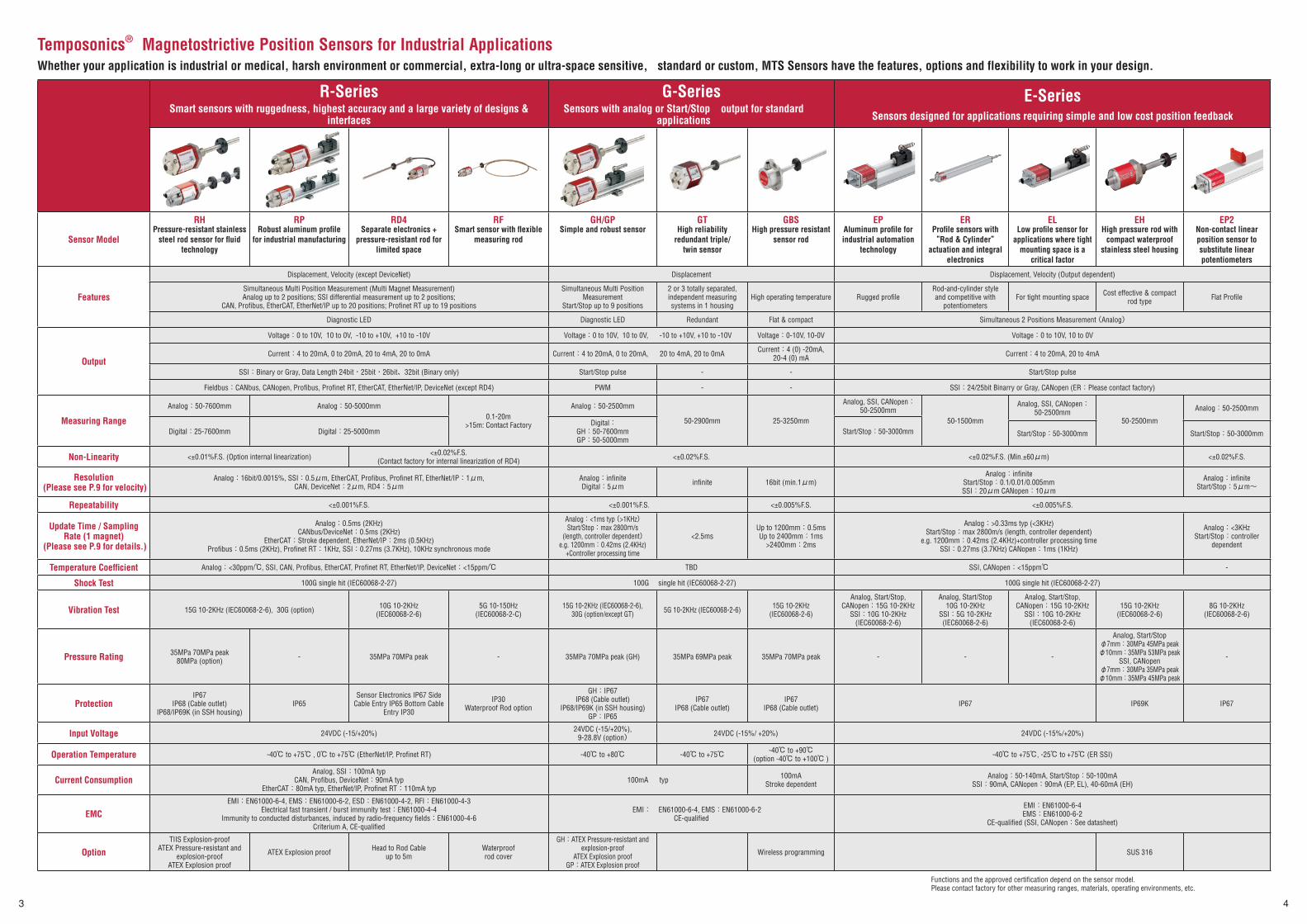
Temposonics® Magnetostrictive Position Sensors for Industrial ApplicationsWhether your application is industrial or medical, harsh environment or commercial, extra-long or ultra-space sensitive, standard or custom, MTS Sensors have the features, options and flexibility to work in your design.
R-SeriesSmart sensors with ruggedness, highest accuracy and a large variety of designs &
interfaces
G-SeriesSensors with analog or Start/Stop output for standard
applications
E-SeriesSensors designed for applications requiring simple and low cost position feedback
Sensor Model
RHPressure-resistant stainless
steel rod sensor for fl uid technology
RPRobust aluminum profi le
for industrial manufacturing
RD4Separate electronics +
pressure-resistant rod for limited space
RFSmart sensor with fl exible
measuring rod
GH/GPSimple and robust sensor
GTHigh reliability
redundant triple/twin sensor
GBSHigh pressure resistant
sensor rod
EPAluminum profi le for industrial automation
technology
ERProfi le sensors with ”Rod & Cylinder”
actuation and integral electronics
ELLow profi le sensor for
applications where tight mounting space is a
critical factor
EHHigh pressure rod with
compact waterproof stainless steel housing
EP2Non-contact linear position sensor to substitute linear potentiometers
Features
Displacement, Velocity (except DeviceNet) Displacement Displacement, Velocity (Output dependent)
Simultaneous Multi Position Measurement (Multi Magnet Measurement) Analog up to 2 positions; SSI differential measurement up to 2 positions;
CAN, Profi bus, EtherCAT, EtherNet/IP up to 20 positions; Profi net RT up to 19 positions
Simultaneous Multi Position Measurement
Start/Stop up to 9 positions
2 or 3 totally separated, independent measuring systems in 1 housing
High operating temperature Rugged profi leRod-and-cylinder style and competitive with
potentiometersFor tight mounting space Cost effective & compact
rod type Flat Profi le
Diagnostic LED Diagnostic LED Redundant Flat & compact Simultaneous 2 Positions Measurement (Analog)
Output
Voltage:0 to 10V, 10 to 0V, -10 to +10V, +10 to -10V Voltage:0 to 10V, 10 to 0V, -10 to +10V, +10 to -10V Voltage:0-10V, 10-0V Voltage:0 to 10V, 10 to 0V
Current:4 to 20mA, 0 to 20mA, 20 to 4mA, 20 to 0mA Current:4 to 20mA, 0 to 20mA, 20 to 4mA, 20 to 0mA Current:4 (0) -20mA, 20-4 (0) mA Current:4 to 20mA, 20 to 4mA
SSI: Binary or Gray, Data Length 24bit・25bit・26bit、32bit (Binary only) Start/Stop pulse - - Start/Stop pulse
Fieldbus:CANbus, CANopen, Profi bus, Profi net RT, EtherCAT, EtherNet/IP, DeviceNet (except RD4) PWM - - SSI:24/25bit Binarry or Gray, CANopen (ER:Please contact factory)
Measuring Range
Analog:50-7600mm Analog:50-5000mm0.1-20m
>15m: Contact Factory
Analog:50-2500mm
50-2900mm 25-3250mm
Analog, SSI, CANopen:50-2500mm
50-1500mm
Analog, SSI, CANopen:50-2500mm
50-2500mm
Analog:50-2500mm
Digital:25-7600mm Digital:25-5000mmDigital:
GH:50-7600mmGP:50-5000mm
Start/Stop:50-3000mm Start/Stop:50-3000mm Start/Stop:50-3000mm
Non-Linearity <±0.01%F.S. (Option internal linearization) <±0.02%F.S. (Contact factory for internal linearization of RD4) <±0.02%F.S. <±0.02%F.S. (Min.±60μm) <±0.02%F.S.
Resolution (Please see P.9 for velocity)
Analog:16bit/0.0015%, SSI:0.5μm, EtherCAT, Profi bus, Profi net RT, EtherNet/IP:1μm, CAN, DeviceNet:2μm, RD4:5μm
Analog:infi nite Digital:5μm infi nite 16bit (min.1μm)
Analog:infi niteStart/Stop:0.1/0.01/0.005mmSSI:20μm CANopen:10μm
Analog:infi nite Start/Stop:5μm~
Repeatability <±0.001%F.S. <±0.001%F.S. <±0.005%F.S. <±0.005%F.S.
Update Time / Sampling Rate (1 magnet)
(Please see P.9 for details.)
Analog:0.5ms (2KHz) CANbus/DeviceNet:0.5ms (2KHz)
EtherCAT:Stroke dependent, EtherNet/IP:2ms (0.5KHz) Profi bus:0.5ms (2KHz), Profi net RT:1KHz, SSI:0.27ms (3.7KHz), 10KHz synchronous mode
Analog:<1ms typ (>1KHz)Start/Stop:max 2800m/s
(length, controller dependent)e.g. 1200mm:0.42ms (2.4KHz)
+Controller processing time
<2.5msUp to 1200mm:0.5msUp to 2400mm:1ms
>2400mm:2ms
Analog:>0.33ms typ (<3KHz)Start/Stop:max 2800m/s (length, controller dependent)
e.g. 1200mm:0.42ms (2.4KHz)+controller processing timeSSI:0.27ms (3.7KHz) CANopen:1ms (1KHz)
Analog:<3KHzStart/Stop:controller
dependent
Temperature Coeffi cient Analog: <30ppm/℃, SSI, CAN, Profi bus, EtherCAT, Profi net RT, EtherNet/IP, DeviceNet: <15ppm/℃ TBD SSI, CANopen:<15ppm℃ -
Shock Test 100G single hit (IEC60068-2-27) 100G single hit (IEC60068-2-27) 100G single hit (IEC60068-2-27)
Vibration Test 15G 10-2KHz (IEC60068-2-6), 30G (option) 10G 10-2KHz (IEC60068-2-6)
5G 10-150Hz(IEC60068-2-C)
15G 10-2KHz (IEC60068-2-6), 30G (option/except GT) 5G 10-2KHz (IEC60068-2-6) 15G 10-2KHz
(IEC60068-2-6)
Analog, Start/Stop, CANopen:15G 10-2KHz
SSI:10G 10-2KHz(IEC60068-2-6)
Analog, Start/Stop10G 10-2KHz
SSI:5G 10-2KHz(IEC60068-2-6)
Analog, Start/Stop, CANopen:15G 10-2KHz
SSI:10G 10-2KHz(IEC60068-2-6)
15G 10-2KHz(IEC60068-2-6)
8G 10-2KHz (IEC60068-2-6)
Pressure Rating 35MPa 70MPa peak 80MPa (option) - 35MPa 70MPa peak - 35MPa 70MPa peak (GH) 35MPa 69MPa peak 35MPa 70MPa peak - - -
Analog, Start/Stopφ7mm:30MPa 45MPa peakφ10mm:35MPa 53MPa peak
SSI, CANopenφ7mm:30MPa 35MPa peakφ10mm:35MPa 45MPa peak
-
ProtectionIP67
IP68 (Cable outlet) IP68/IP69K (in SSH housing)
IP65Sensor Electronics IP67 Side
Cable Entry IP65 Bottom Cable Entry IP30
IP30 Waterproof Rod option
GH:IP67IP68 (Cable outlet)
IP68/IP69K (in SSH housing)GP:IP65
IP67 IP68 (Cable outlet)
IP67 IP68 (Cable outlet) IP67 IP69K IP67
Input Voltage 24VDC (-15/+20%) 24VDC (-15/+20%),9-28.8V (option) 24VDC (-15%/ +20%) 24VDC (-15%/+20%)
Operation Temperature -40℃ to +75℃ , 0℃ to +75℃ (EtherNet/IP, Profi net RT) -40℃ to +80℃ -40℃ to +75℃ -40℃ to +90℃(option -40℃ to +100℃ ) -40℃ to +75℃, -25℃ to +75℃ (ER SSI)
Current ConsumptionAnalog, SSI:100mA typ
CAN, Profi bus, DeviceNet:90mA typEtherCAT:80mA typ, EtherNet/IP, Profi net RT:110mA typ
100mA typ 100mA Stroke dependent
Analog:50-140mA, Start/Stop:50-100mASSI:90mA, CANopen:90mA (EP, EL), 40-60mA (EH)
EMCEMI:EN61000-6-4, EMS:EN61000-6-2, ESD:EN61000-4-2, RFI:EN61000-4-3
Electrical fast transient / burst immunity test:EN61000-4-4Immunity to conducted disturbances, induced by radio-frequency fi elds:EN61000-4-6
Criterium A, CE-qualifi ed
EMI: EN61000-6-4, EMS:EN61000-6-2CE-qualifi ed
EMI:EN61000-6-4EMS:EN61000-6-2
CE-qualifi ed (SSI, CANopen:See datasheet)
OptionTIIS Explosion-proof
ATEX Pressure-resistant and explosion-proof
ATEX Explosion proof
ATEX Explosion proof Head to Rod Cable up to 5m
Waterproof rod cover
GH:ATEX Pressure-resistant and explosion-proof
ATEX Explosion proofGP:ATEX Explosion proof
Wireless programming SUS 316
Functions and the approved certifi cation depend on the sensor model.Please contact factory for other measuring ranges, materials, operating environments, etc.
セレクションガイド-英語版cs4.indd 3-4セレクションガイド-英語版cs4.indd 3-4 2014/03/20 11:302014/03/20 11:30プロセスシアンプロセスシアンプロセスマゼンタプロセスマゼンタプロセスイエロープロセスイエロープロセスブラックプロセスブラック
5
5
6
6
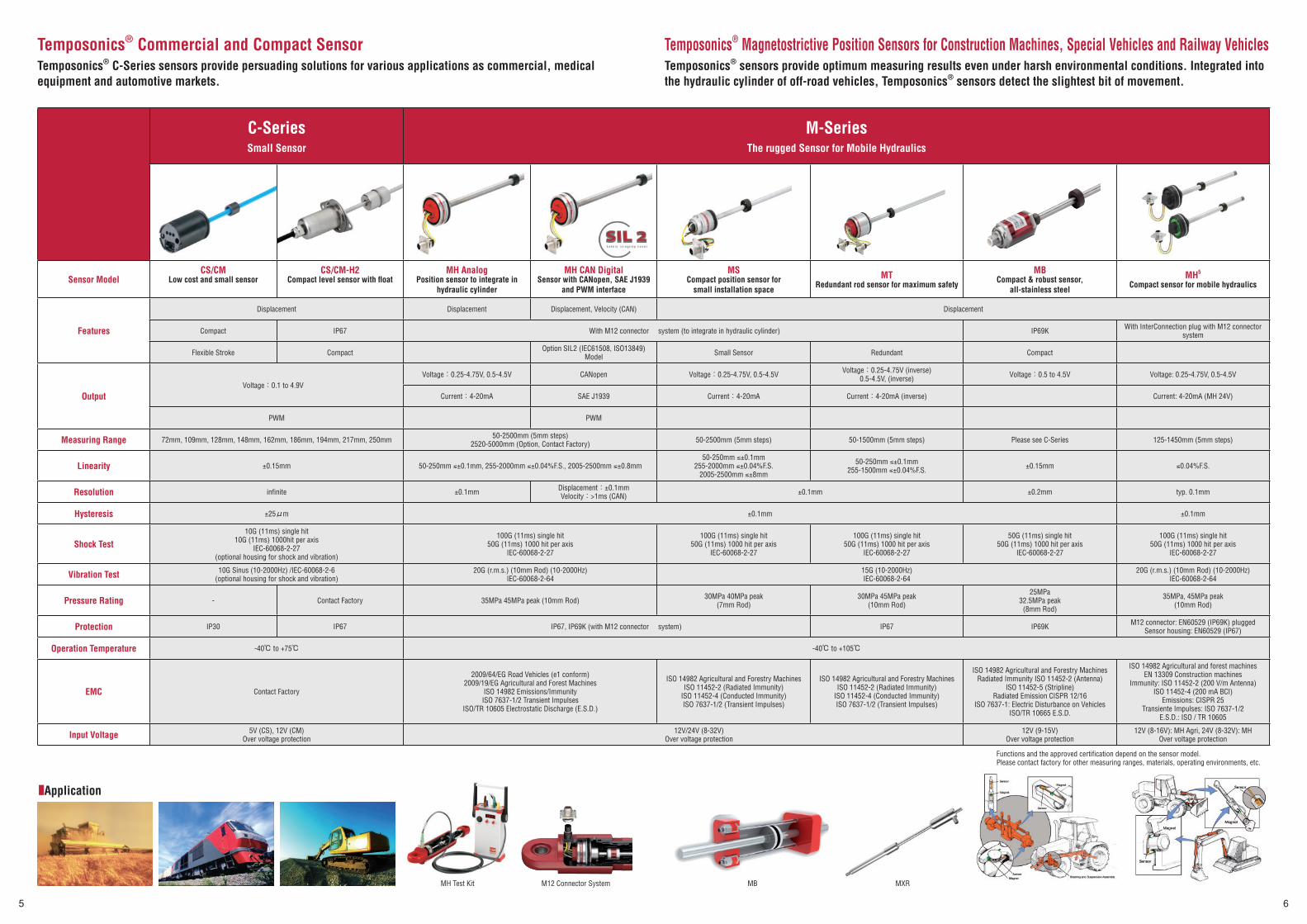
Temposonics® Commercial and Compact SensorTemposonics® C-Series sensors provide persuading solutions for various applications as commercial, medical equipment and automotive markets.
C-SeriesSmall Sensor
M-SeriesThe rugged Sensor for Mobile Hydraulics
Sensor ModelCS/CM
Low cost and small sensorCS/CM-H2
Compact level sensor with fl oatMH Analog
Position sensor to integrate in hydraulic cylinder
MH CAN DigitalSensor with CANopen, SAE J1939
and PWM interface
MSCompact position sensor for
small installation space
MTRedundant rod sensor for maximum safety
MBCompact & robust sensor,
all-stainless steel
MH5
Compact sensor for mobile hydraulics
Features
Displacement Displacement Displacement, Velocity (CAN) Displacement
Compact IP67 With M12 connector system (to integrate in hydraulic cylinder) IP69K With InterConnection plug with M12 connector system
Flexible Stroke Compact Option SIL2 (IEC61508, ISO13849) Model Small Sensor Redundant Compact
OutputVoltage:0.1 to 4.9V
Voltage:0.25-4.75V, 0.5-4.5V CANopen Voltage:0.25-4.75V, 0.5-4.5V Voltage:0.25-4.75V (inverse) 0.5-4.5V, (inverse) Voltage:0.5 to 4.5V Voltage: 0.25-4.75V, 0.5-4.5V
Current:4-20mA SAE J1939 Current:4-20mA Current:4-20mA (inverse) Current: 4-20mA (MH 24V)
PWM PWM
Measuring Range 72mm, 109mm, 128mm, 148mm, 162mm, 186mm, 194mm, 217mm, 250mm 50-2500mm (5mm steps)2520-5000mm (Option, Contact Factory) 50-2500mm (5mm steps) 50-1500mm (5mm steps) Please see C-Series 125-1450mm (5mm steps)
Linearity ±0.15mm 50-250mm ≤±0.1mm, 255-2000mm ≤±0.04%F.S., 2005-2500mm ≤±0.8mm50-250mm ≤±0.1mm
255-2000mm ≤±0.04%F.S.2005-2500mm ≤±8mm
50-250mm ≤±0.1mm255-1500mm ≤±0.04%F.S. ±0.15mm ≤0.04%F.S.
Resolution infi nite ±0.1mm Displacement:±0.1mmVelocity:>1ms (CAN) ±0.1mm ±0.2mm typ. 0.1mm
Hysteresis ±25μm ±0.1mm ±0.1mm
Shock Test10G (11ms) single hit
10G (11ms) 1000hit per axisIEC-60068-2-27
(optional housing for shock and vibration)
100G (11ms) single hit50G (11ms) 1000 hit per axis
IEC-60068-2-27
100G (11ms) single hit50G (11ms) 1000 hit per axis
IEC-60068-2-27
100G (11ms) single hit50G (11ms) 1000 hit per axis
IEC-60068-2-27
50G (11ms) single hit50G (11ms) 1000 hit per axis
IEC-60068-2-27
100G (11ms) single hit50G (11ms) 1000 hit per axis
IEC-60068-2-27
Vibration Test 10G Sinus (10-2000Hz) /IEC-60068-2-6(optional housing for shock and vibration)
20G (r.m.s.) (10mm Rod) (10-2000Hz)IEC-60068-2-64
15G (10-2000Hz)IEC-60068-2-64
20G (r.m.s.) (10mm Rod) (10-2000Hz)IEC-60068-2-64
Pressure Rating - Contact Factory 35MPa 45MPa peak (10mm Rod) 30MPa 40MPa peak(7mm Rod)
30MPa 45MPa peak(10mm Rod)
25MPa32.5MPa peak
(8mm Rod)
35MPa, 45MPa peak(10mm Rod)
Protection IP30 IP67 IP67, IP69K (with M12 connector system) IP67 IP69K M12 connector: EN60529 (IP69K) pluggedSensor housing: EN60529 (IP67)
Operation Temperature -40℃ to +75℃ -40℃ to +105℃
EMC Contact Factory
2009/64/EG Road Vehicles (e1 conform)2009/19/EG Agricultural and Forest Machines
ISO 14982 Emissions/ImmunityISO 7637-1/2 Transient Impulses
ISO/TR 10605 Electrostatic Discharge (E.S.D.)
ISO 14982 Agricultural and Forestry MachinesISO 11452-2 (Radiated Immunity)
ISO 11452-4 (Conducted Immunity)ISO 7637-1/2 (Transient Impulses)
ISO 14982 Agricultural and Forestry MachinesISO 11452-2 (Radiated Immunity)
ISO 11452-4 (Conducted Immunity)ISO 7637-1/2 (Transient Impulses)
ISO 14982 Agricultural and Forestry MachinesRadiated Immunity ISO 11452-2 (Antenna)
ISO 11452-5 (Stripline)Radiated Emission CISPR 12/16
ISO 7637-1: Electric Disturbance on VehiclesISO/TR 10665 E.S.D.
ISO 14982 Agricultural and forest machinesEN 13309 Construction machines
Immunity: ISO 11452-2 (200 V/m Antenna)ISO 11452-4 (200 mA BCI)
Emissions: CISPR 25Transiente Impulses: ISO 7637-1/2
E.S.D.: ISO / TR 10605
Input Voltage 5V (CS), 12V (CM)Over voltage protection
12V/24V (8-32V)Over voltage protection
12V (9-15V)Over voltage protection
12V (8-16V): MH Agri, 24V (8-32V): MHOver voltage protection
Functions and the approved certifi cation depend on the sensor model.Please contact factory for other measuring ranges, materials, operating environments, etc.
MH Test Kit
■Application
M12 Connector System
Temposonics® Magnetostrictive Position Sensors for Construction Machines, Special Vehicles and Railway VehiclesTemposonics® sensors provide optimum measuring results even under harsh environmental conditions. Integrated into the hydraulic cylinder of off-road vehicles, Temposonics® sensors detect the slightest bit of movement.
MB MXR
セレクションガイド-英語版cs4.indd 5-6セレクションガイド-英語版cs4.indd 5-6 2014/03/20 11:312014/03/20 11:31プロセスシアンプロセスシアンプロセスマゼンタプロセスマゼンタプロセスイエロープロセスイエロープロセスブラックプロセスブラック

7
7
8
8
Level Plus® Magnetostrictive Liquid-Level TransmittersToday’s storage facilities and processing operations demand innovation, accuracy, cost-effectiveness and reliability. Our Level Plus® liquid-level transmitters work well in continuous and batch process control, bulk storage, precision inventory control, product level, interface level, and temperature monitoring applications. A wide choice of interfaces (Analog, HART®, Modbus / DDA / FOUNDATION™ fieldbus) are available.
MODEL MC420Analog Output
MODEL MRAnalog Output
MODEL MGDigital Output
MODEL USTDⅡDigital Output
Digital Output
Model MC420 MR Sanitary MR Industrial MR Flexible MG Sanitary MG Industrial MG Flexible USTDⅡ
Measured Variable Product Level or Interface Level Product Level, Interface Level & Temperature (3 in 1) Product Level, Interface Level & Temperature (3 in 1) Product Level, Interface Level & Temperature (3 in 1)
Features HART® 3A, CIP, SIP, DIP Stainless Rod Stainless Flexible Rod
3A, CIP, SIP, DIP Stainless Rod Stainless Flexible Rod For underground storage tanksAverage and multipoint temperatures
measurement max 5 pointNo recalibration
Gross observed volume of product, interface, total and ullage Average and multipoint temperatures max 12 point 100 point Strap Table (Product level memory) setup
Output 4-20 mA with HART® 4-20 mA with HART®, 1 or 2 loop Modbus RTU, DDA, FOUNDATION™ fi eldbus DDA
Order Length 457-5486mm 508-7620mm 3048-12200mm 508-7620mm 3048-22000mm 737-3785mm
Non-Linearity 0.02% F.S. or 0.794 mm whichever is greater 0.02% F.S. or 0.794mm whichever is greater Inherent Accuracy:±1mm ±0.5mm
Resolution infi nite infi nite 0.025mm -
Repeatability 0.01% F.S. or 0.381mm whichever is greater 0.01% F.S. or 0.381mm whichever is greater Hysterisis:0.002% F.S or 0.397mm whichever is greater 0.001% F.S. or 0.381 mm whichever is greater
Humidity 0-100%R.H. 0-100%R.H. 0-100%R.H. 0-100%R.H.
Temperature Accuracy - ±1.5℃ ±0.28℃ Modbus:max 12 point, DDA/FOUNDATION™ fi eldbus:max 5 point ±0.28℃ max 5 point
Operating Temperature Electronics
-34℃ to +71℃ -40℃ to +71℃ -40℃ to +71℃ -40℃ to +71℃
Operating Temperature Sensing Element
-40℃ to +125℃ -40℃ to +125℃ -40℃ to +125℃ -40℃ to +125℃
Input Voltage 10.5-36VDC 10.5-36VDC Modbus/DDA:10.5-30.1VDCFOUNDATION™ fi eldbus:9-32VDC 10.5-30.1VDC
Wetted Parts Material 316L SS 316L SS, Ra25 or Ra 15 Finish 316L SS, Hastelloy, Tefl on 316L SS 316L SS, Ra25 or Ra 15 Finish 316L SS, Hastelloy, Tefl on 316L SS 316L SS
Enclosure Rating NEMA Type 4X NEMA Type 4X NEMA Type 4X IP68
EMC Line-to-ground surge suppression: IEC61000-4-5Line-to-line and line-to-ground transient suppressors:IEC61000-4-4
Line-to-ground surge suppression: IEC61000-4-5Line-to-line and line-to- ground transient suppressors:IEC61000-4-4
Haza
rdou
s Ar
ea A
ppro
val
TIIS (Japan) - - - Intrinsically Safe, Ex ia ⅡB T4
NEPSI (China) - - Explosion Proof, Ex d ⅡB T4 Intrinsically Safe, Ex ia ⅡC T4
FMIntrinsically Safe, Class Ⅰ Div. 1 Intrinsically Safe, Class Ⅰ Div. 1 Intrinsically Safe, Class Ⅰ Div. 1 Intrinsically Safe, Class Ⅰ Div. 1
- Explosion Proof, Class Ⅰ, Div. 1, Groups B, C, D Explosion Proof, Class Ⅰ, Div. 1, Groups B, C, D -
CSAIntrinsically Safe, Class Ⅰ Div. 1 Intrinsically Safe, Class Ⅰ Div. 1 Intrinsically Safe, Class Ⅰ Div. 1 -
- Explosion Proof, Class Ⅰ, Div. 1, Groups B, C, D Explosion Proof, Class Ⅰ, Div. 1, Groups B, C, D -
ATEXIntrinsically Safe, Ex ia ⅡB T4 Intrinsically Safe, Ex ia ⅡB T4 Intrinsically Safe, EEx ia ⅡB T4 Intrinsically Safe, EEx ia ⅡB T4
- Flame Proof Ex d ⅡB T4 Ga/Gb Flame Proof Ex d ⅡB T4 6a/6b -
IEC Ex - Flame Proof Ex d ⅡB T4 Ga/Gb Flame Proof Ex d ⅡB T4 6a/6b -
Functions and the approved certifi cation depend on the sensor model. Please contact factory for other measuring ranges, materials, operating environments, etc.
・Float & Weight
・Hand Held Terminal
・Control Panel
・LED Display
■Option ■Illustration of Volumes Measured by M-Series Liquid Level Transmitter
GOVT = Gross Observed Volume of the Total
GOVP = Gross Observed Volume of the Product
GOVI = Gross Observed Volume of the Interface
GOVU = Gross Observed Volume of the Ullage
NSVP = Net Standard Product Volume (GOVP x Volume Correction Factor)
Magnet
LevelBottom
Minimize dead zone
■Application
WORKING CAPACITY 80% FULL
GOVP GOVT=(GOVP + GOVI)
GOVI
GOVU
90-Degree Electronic Mounting
セレクションガイド-英語版cs4.indd 7-8セレクションガイド-英語版cs4.indd 7-8 2014/03/20 11:312014/03/20 11:31プロセスシアンプロセスシアンプロセスマゼンタプロセスマゼンタプロセスイエロープロセスイエロープロセスブラックプロセスブラック

9
9
10
10
Option/Accessories/Supplementary Data■Explosion Proof Option
Explosion Proof Type Approved Sensors
Explosion proofATEX Ex nA Ⅱ C T4 Gc
RH-AnalogRH-CANbusRH-SSIRP-AnalogRP-CANbus
RP-SSIGH-AnalogGH-Start/StopGP-AnalogGP-Start/Stop
Pressure-resistant and explosion-proof ATEX Ex d ⅡC T5 Tamb -40℃ to +60℃
UL Class1, Devision1, Group A, B, C and Dwith High Pressure Housing (HPH) IP68
RH-AnalogRH-Profi busRH-CANbusRH-SSI
RH-DeviceNetGH-AnalogGH-Start/StopGH-PWM
Explosion-proof TIIS Ex d ⅡB H2T6
RH-AnalogCurrent 4-20mA
Intrinsically safeATEX EEx ia ⅡA T4 (Liquid Level)ATEX EEx ia ⅡB T4 (Liquid Level)
TIIS Ex ia ⅡT4 (Liquid Level)
Liquid Level Transmitters
Waterproof Housing
Protection:IP68, IP69K
Material:304 SS or 316L SS
Application:RH-Analog/Profi bus/SSI/CANbus/
DeviceNet/EtherCAT/GH-Analog/Digital
■Waterproof Option
■Update Time/Sampling Rate
ModelMeasuring Length (mm)
300 500 750 1000 1200 2000 2400 4500 4800 5000 7600R-Analog 0.5ms 2KHz 1ms 1KHz 2ms 0.5KHz 5ms 0.2KHz
R-CANbus 0.5ms 2KHz (up to 1200 mm for CANbasic only), 1ms 1KHz (25-2400mm) 2ms 0.5KHz 4ms 0.25KHz
R-DeviceNet 0.5ms 2KHz 1ms 1KHz 2ms 0.5KHz 4ms 0.25KHz
R-EtherCAT Stroke dependent
R-EtherNet/IP 2ms 0.5KHz 4ms 0.25KHz
R-Profi bus 0.5ms 2KHz 1ms 1KHz 2ms 0.5KHz 3.1ms 0.32KHz
R-SSI* 0.27ms 3.7KHz 0.33ms 3KHz 0.43ms 2.3KHz 0.83ms 1.2KHz 2ms 0.5KHz
GH/GP-Analog <1ms typ >1KHz
GH/GP-Digital max 2800m/s measuring length, controller dependent, e.g. 1200mm 0.42ms 2.4KHz+controller processing time
GT <1ms typ >1KHz up to 2900mm
GBS 0.5ms 1ms 2ms up to 3250mm
E-Analog <3KHz up to 2500mm (ER:up to 1500mm)
E-Start/Stop max 2800m/s measuring length, controller dependent up to 3000mm
C-Series 2ms 500Hz
*10KHz synchronous mode option
■Programmer/Display
Product Function Application
Hand-Held Programmer253124 (R-Analog)253853 (G-Analog)
Null/Span adjustment in the fi eld R-AnalogG-Analog
USB-Programmer AnalogIncl. power supply, USB-cable, sensor-cable and software253134-1 (R-Analog)253145-1(G-Analog)
Null/Span adjustmentVelocity rangeAssignment of output to measured position or velocityError output value
R-AnalogG-Analog
USB-Programmer SSIIncl. power supply, USB-cable, sensor-cable and software253135-1
Data length, data format, resolution, measuring directionSynchronous / asynchronous measurement, offset positionError, measurement fi lter, differential measurement
R-SSIGB-SSI
USB-Programmer Start/Stop, PWMIncl. power supply, USB-cable, sensor-cable and software253146-1
Start/Stop, PWM parameter setup G-Start/Stop, PWM
Profi bus Address Programmer Kit280640
Slave address setup R-Profi bus
CANopen Address Programmer252382-D62 (for M16 connector)252382-D62A (for M16 90° connector)
Node-address setup R-CANopen
Cabinet-Programmer253408
Null/Span adjustment35mm DIN rail mounting R-Analog
Profi bus Master Simulator401727
Sensor function checkSlave address changeMagnet positions and diagnostic data read out
R-Profi bus
Profi bus Filter Box252916
24VDC power supply fi lterEMC R-Profi bus
M-Series Analog/PWM/CAN Test Kit (charge type)Incl. AC adapter, cable, case and software280618 (Analog/PWM)254267 (CAN)
Input voltage signal 0-10V, input current signal 4-20mAPWM/CAN signal inputPower supply output for 5V/12V sensor
M-Analog, PWM, CAN
IX345 6-segment LED SSI DisplayBuilt-in power supplyIX345
SSI signal inputInput voltage: AC115-230VMeasured value displayPower supply output for 24V sensor
R-SSI
SSI Interface (Serial-Parallel Conversion)SSI-1016EC (NPN)SSI-1016G (PNP)
Input voltage:24VDCInput signal:SSI (24/25/26bit Binary/Gray)Output signal:Parallel (open collector)
R-SSI
AK288 (Start/Stop-Analog Conversion)AK288
Input voltage:24VDCInput signal:Start/StopOutput signal:Analog (voltage 0-10V, current 4-20mA)
G-Start/Stop
■Multi Position MagnetModel R-Analog R-SSI R-CANbus/R-Profi bus/R-EtherCAT/EtherNet/IP R-Profi net G-Start/Stop
Number of Magnet 2 Differential measurement between 2 magnets 20 19 9
■Cable Extension OptionModel R-SSI R-CANbus R-DeviceNet
Data Speed 1MBd 400kBd 300kBd 200kBd 100kBd 1.0MBd 500kBd 250kBd 125kBd 500kBd 250kBd 125kBd
Max Length 3m 50m 100m 200m 400m 25m 100m 250m 500m 100m 250m 500m
Model R-Profi bus G-Analog G-Start/Stop, PWM
Data Speed 12MBd 1.5MBd 500kBd 187.5kBd 93.75kBd - -
Max Length 100m 200m 400m 1000m 1200m 45m 90m
■Interface
■Resolution for Velocity Measurement
Reso
lutio
n R-Analog R-CANopen R-CANbasic R-EtherCAT R-Profi bus R-SSI
0.1mm/s0.01mm/s(Option)
0.5mm/s(5μm)
1.0mm/s(5μm) 1μm/s
(Stroke dependent)
up to 500mm0.64mm/s
up to 4500mm0.21mm/s velocity over 10 measured values:
0.1 mm/s at 1 ms cycle time0.2mm/s(2μm)
0.1mm/s(2μm)
up to 2000mm0.43mm/s
up to 7600mm0.14mm/s
セレクションガイド-英語版cs4.indd 9-10セレクションガイド-英語版cs4.indd 9-10 2014/03/20 11:322014/03/20 11:32プロセスシアンプロセスシアンプロセスマゼンタプロセスマゼンタプロセスイエロープロセスイエロープロセスブラックプロセスブラック
11
11
12
12
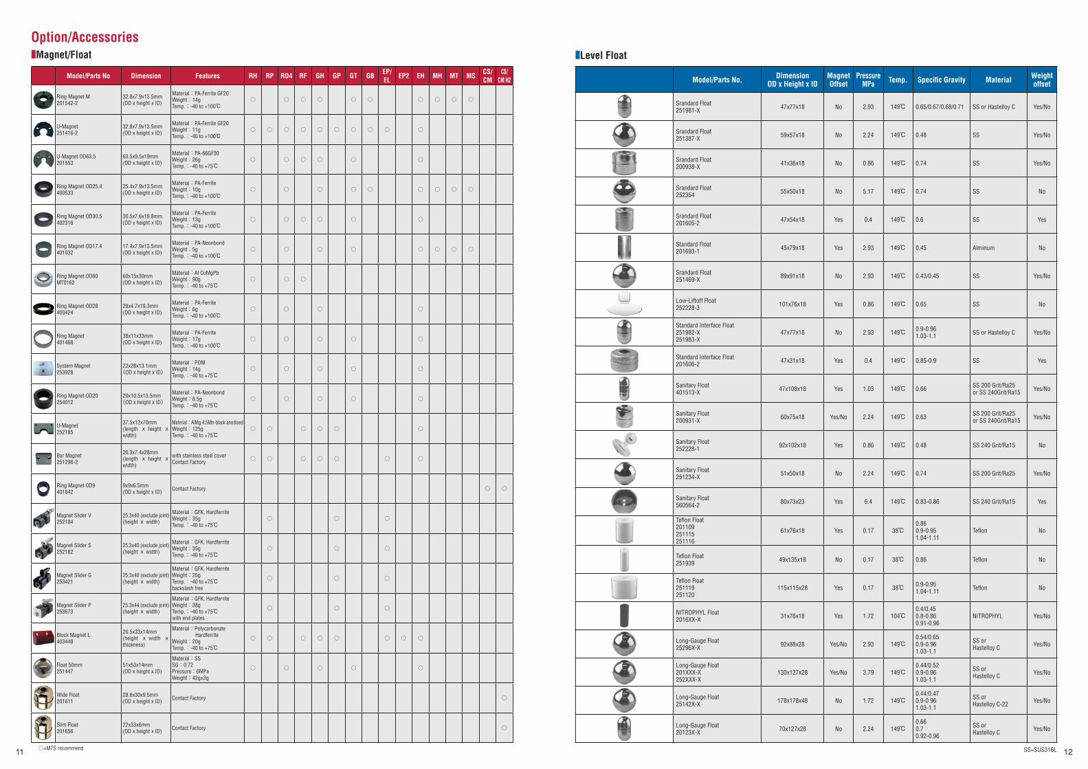
Option/Accessories■Magnet/Float ■Level Float
Model/Parts No Dimension Features RH RP RD4 RF GH GP GT GB EP/EL EP2 EH MH MT MS CS/
CMCS/
CM H2
Ring Magnet M201542-2
32.8x7.9x13.5mm(OD x height x ID)
Material:PA-Ferrite GF20Weight:14gTemp.:-40 to +100℃
○ ○ ○ ○ ○ ○ ○ ○ ○ ○
U-Magnet251416-2
32.8x7.9x13.5mm(OD x height x ID)
Material:PA-Ferrite GF20Weight:11gTemp.:-40 to +100℃
○ ○ ○ ○ ○ ○ ○ ○ ○ ○
U-Magnet OD63.5201553
63.5x9.5x19mm(OD x height x ID)
Material:PA-66GF30Weight:26gTemp.:-40 to +75℃
○ ○ ○ ○ ○ ○
Ring Magnet OD25.4400533
25.4x7.9x13.5mm(OD x height x ID)
Material:PA-FerriteWeight:10gTemp.:-40 to +100℃
○ ○ ○ ○ ○ ○ ○ ○ ○
Ring Magnet OD30.5402316
30.5x7.6x19.8mm(OD x height x ID)
Material:PA-FerriteWeight:13gTemp.:-40 to +100℃
○ ○ ○ ○ ○ ○
Ring Magnet OD17.4401032
17.4x7.9x13.5mm(OD x height x ID)
Material:PA-NeonbondWeight:5g Temp.:-40 to +100℃
○ ○ ○ ○ ○ ○ ○ ○
Ring Magnet OD60MT0162
60x15x30mm(OD x height x ID)
Material:Al CuMgPbWeight:90gTemp.:-40 to +75℃
○ ○ ○
Ring Magnet OD28400424
28x4.7x19.3mm(OD x height x ID)
Material:PA-FerriteWeight:6gTemp.:-40 to +100℃
○ ○ ○ ○
Ring Magnet401468
38x11x33mm(OD x height x ID)
Material:PA-FerriteWeight:17gTemp.:-40 to +100℃
○ ○ ○ ○ ○
System Magnet253928
22x28x13.1mm(OD x height x ID)
Material:POMWeight:14gTemp.:-40 to +75℃
○ ○ ○ ○ ○
Ring Magnet OD20254012
20x10.5x13.5mm(OD x height x ID)
Material:PA-NeonbondWeight:8.5gTemp.:-40 to +75℃
○ ○ ○ ○ ○
U-Magnet252185
37.5x12x70mm(length x height x width)
Material:AlMg 4.5Mn-black anodised Weight:125gTemp.:-40 to +75℃
○ ○ ○ ○ ○ ○
Bar Magnet251298-2
20.3x7.4x28mm(length x height x width)
with stainless steel coverContact Factory
○ ○ ○ ○ ○ ○ ○
Ring Magnet OD9401842
9x9x6.5mm(OD x height x ID) Contact Factory ○ ○
Magnet Slider V252184
25.3x40 (exclude joint)(height x width)
Material:GFK, HardferriteWeight:35gTemp.:-40 to +75℃
○ ○ ○
Magnet Slider S252182
25.3x40 (exclude joint)(height x width)
Material:GFK, HardferriteWeight:35gTemp.:-40 to +75℃
○ ○ ○
Magnet Slider G253421
25.3x40 (exclude joint)(height x width)
Material:GFK, HardferriteWeight:25gTemp.:-40 to +75℃backslash free
○ ○ ○
Magnet Slider P253673
25.3x44 (exclude joint)(height x width)
Material:GFK, HardferriteWeight:38gTemp.:-40 to +75℃with end plates
○ ○ ○
Block Magnet L403448
20.5x33x14mm(height x width x thickness)
Material:Polycarbonate Hardferrite
Weight:20g Temp.:-40 to +75℃
○ ○ ○ ○ ○ ○ ○ ○
Float 50mm251447
51x53x14mm(OD x height x ID)
Material:SSSG:0.72Pressure:6MPaWeight:42g±3g
○ ○ ○ ○ ○
Wide Float201611
28.6x30x9.5mm(OD x height x ID) Contact Factory ○
Slim Float201656
22x33x6mm(OD x height x ID) Contact Factory ○
○=MTS recommend
Model/Parts No. DimensionOD x Height x ID
Magnet Offset
Pressure MPa Temp. Specifi c Gravity Material Weight
offset
Srandard Float251981-X 47x77x18 No 2.93 149℃ 0.65/0.67/0.68/0.71 SS or Hastelloy C Yes/No
Srandard Float251387-X 59x57x18 No 2.24 149℃ 0.48 SS Yes/No
Srandard Float200938-X 41x36x18 No 0.86 149℃ 0.74 SS Yes/No
Srandard Float252354 55x50x18 No 5.17 149℃ 0.74 SS No
Srandard Float201605-2 47x54x18 Yes 0.4 149℃ 0.6 SS Yes
Standard Float201693-1 45x79x18 Yes 2.93 149℃ 0.45 Alminum No
Srandard Float251469-X 89x91x18 No 2.93 149℃ 0.43/0.45 SS Yes/No
Low-Liftoff Float252228-3 101x76x18 Yes 0.86 149℃ 0.65 SS No
Standard Interface Float251982-X251983-X
47x77x18 No 2.93 149℃ 0.9-0.961.03-1.1 SS or Hastelloy C Yes/No
Standard Interface Float201606-2 47x31x18 Yes 0.4 149℃ 0.85-0.9 SS Yes
Sanitary Float401513-X 47x108x18 Yes 1.03 149℃ 0.66 SS 200 Grit/Ra25
or SS 240Grit/Ra15 Yes/No
Sanitary Float200931-X 60x75x18 Yes/No 2.24 149℃ 0.63 SS 200 Grit/Ra25
or SS 240Grit/Ra15 Yes/No
Sanitary Float252228-1 92x102x18 Yes 0.86 149℃ 0.48 SS 240 Grit/Ra15 No
Sanitary Float251234-X 51x50x18 No 2.24 149℃ 0.74 SS 200 Grit/Ra25 Yes/No
Sanitary Float560564-2 80x73x23 Yes 6.4 149℃ 0.83-0.86 SS 240 Grit/Ra15 Yes
Tefl on Float201109251115251116
61x76x18 Yes 0.17 38℃0.860.9-0.951.04-1.11
Tefl on No
Tefl on Float251939 49x135x18 No 0.17 38℃ 0.86 Tefl on No
Tefl on Float251119251120
115x115x28 Yes 0.17 38℃ 0.9-0.951.04-1.11 Tefl on No
NITROPHYL Float2016XX-X 31x76x18 Yes 1.72 104℃
0.4/0.450.8-0.860.91-0.96
NITROPHYL Yes/No
Long-Gauge Float25296X-X 92x88x28 Yes/No 2.93 149℃
0.54/0.650.9-0.961.03-1.1
SS orHastelloy C Yes/No
Long-Gauge Float201XXX-X252XXX-X
130x127x28 Yes/No 3.79 149℃0.44/0.520.9-0.961.03-1.1
SS orHastelloy C Yes/No
Long-Gauge Float25142X-X 178x178x48 No 1.72 149℃
0.44/0.470.9-0.961.03-1.1
SS orHastelloy C-22 Yes/No
Long-Gauge Float20123X-X 70x127x28 No 2.24 149℃
0.660.70.92-0.96
SS orHastelloy C Yes/No
SS=SUS316L
セレクションガイド-英語版cs4.indd 11-12セレクションガイド-英語版cs4.indd 11-12 2014/03/20 11:322014/03/20 11:32プロセスシアンプロセスシアンプロセスマゼンタプロセスマゼンタプロセスイエロープロセスイエロープロセスブラックプロセスブラック
13
13
14
14
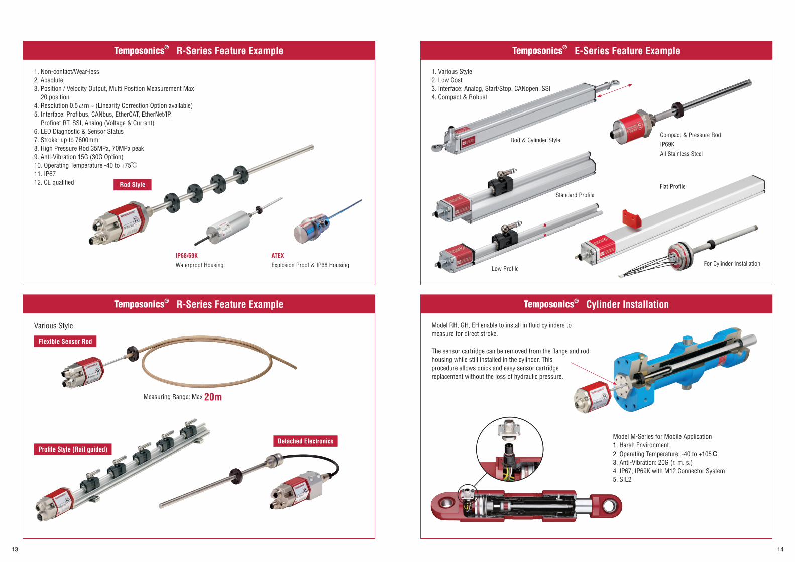
Temposonics® R-Series Feature Example Temposonics® E-Series Feature Example
Temposonics® R-Series Feature Example Temposonics® Cylinder Installation
1. Non-contact/Wear-less2. Absolute3. Position / Velocity Output, Multi Position Measurement Max
20 position4. Resolution 0.5μm ~ (Linearity Correction Option available)5. Interface: Profibus, CANbus, EtherCAT, EtherNet/IP,
Profinet RT, SSI, Analog (Voltage & Current)6. LED Diagnostic & Sensor Status7. Stroke: up to 7600mm 8. High Pressure Rod 35MPa, 70MPa peak9. Anti-Vibration 15G (30G Option)10. Operating Temperature -40 to +75℃11. IP6712. CE qualified
Various Style
Model M-Series for Mobile Application1. Harsh Environment2. Operating Temperature: -40 to +105℃3. Anti-Vibration: 20G (r. m. s.)4. IP67, IP69K with M12 Connector System5. SIL2
IP68/69K
Waterproof Housing
ATEX
Explosion Proof & IP68 Housing
Flexible Sensor Rod
Profi le Style (Rail guided)Detached Electronics
Measuring Range: Max 20m
Model RH, GH, EH enable to install in fluid cylinders to measure for direct stroke.
The sensor cartridge can be removed from the flange and rod housing while still installed in the cylinder. This procedure allows quick and easy sensor cartridge replacement without the loss of hydraulic pressure.
1. Various Style2. Low Cost3. Interface: Analog, Start/Stop, CANopen, SSI4. Compact & Robust
Rod & Cylinder Style
Flat Profile
Compact & Pressure Rod
IP69K
All Stainless Steel
Low Profile
Rod Style
Standard Profile
For Cylinder Installation
セレクションガイド-英語版cs4.indd 13-14セレクションガイド-英語版cs4.indd 13-14 2014/03/20 11:342014/03/20 11:34プロセスシアンプロセスシアンプロセスマゼンタプロセスマゼンタプロセスイエロープロセスイエロープロセスブラックプロセスブラック