nasa ames simulation laboratories year in review 2004
TRANSCRIPT

NASA Ames Simulation LaboratoriesYear in Review
2004
2 Aviation Systems Division
Special thanks to Tom Alderete, Debbi Ballinger, Steve Belsley, Jim Blount, David Brown, John Bunnell, Dave Carothers, Diane Carpenter, Girish Chachad, Paul Chaplin, David Chin, Robert Cornell, Thomas Crawford, Greg Davis, Nancy Dorighi, Ron Gerdes, Dean Giovannetti, Claudine Herbelin, Estela Hernandez, Jeff Hernandez, Jeff Homan, Srba Jovic, Rod Ketchum, Linton Kypta, Soren LaForce, Ron Lehmer, Emily Lewis, Ian Maclure, Mike Madsen, Joe Mastroieni, Jim Miller, Bob Morrison, Chris Murphy, Khoa Nguyen, Ramesh Panda, Marty Pethtel, Terry Rager, Charley Ross, Ghislain Saillant, Russ Sansom, Barry Sullivan, Duc Tran, Phil Tung, Gary Uyehara, Cedric Walker, and Patrick Wang for contributions made to the 2004 report.
This document was produced by: Kathleen Starmer, Northrop Grumman Information Technology.
Acknowledgements

5 Executive Summary
7 Simulation Facilities
11 Research at SimLabs
12 Space Shuttle Vehicle: 2003-200414 Cockpit Display of
Traffi c Information15 Distributed Air/Ground
Traffi c Management Demonstrations 2004
16 Aircraft Landing Lights to Enhance Runway Traffi c Safety
17 Joint Strike Fighter 200418 FAA Obstacle Clearance Panel
Simulation19 CH-47 Digital Advanced
Flight Control System
21 Research-Directed Projects at SimLabs
22 Virtual Airspace Simulation Technology-Real-Time
24 Lunar Lander Module Demonstration at the Vertical Motion Simulator
25 Mars Database Development at FutureFlight Central
26 Voice Communication System Upgrade
27 High Level Architecture Enhancements at FutureFlight Central
28 Contact Information
Contents
Labs, located at NASA es Research Center in
Moffett Field, California, houses some of the most sophisticated simulation facilities in the world. We support a wide range of
research, with emphasis on aerospace vehicles, integrated system-level simulation, human factors, accident
investigations, and studies aimed at improving aviation safety. SimLabs has partnered with numerous NASA programs over the years, as well as with other government agencies, industry, and academia, and is strategically important in meeting the Nation’s present and future aerospace needs.
SSimimAmeAm

4 Aviation Systems Division
The FutureFlight Central tower cab provides a spectacular 360-degree fi eld-of-view.
CFFC

Aviation Systems Division 5
Executive Summary
d to present our Year in Review2004. This report documents the earch and Technology Projectsn the Simulation Laboratoriesfulfi ll vital roles in NASA’s
Missions. During the past year—and as it hasfor four decades—SimLabs has made essential contributions to fl ight vehicle development, aviation safety, Space Shuttle landing operations, fl ight control and display systems, and the national airspace system. Although the utilization of SimLabs has changed signifi cantly over the years with the evolution of NASA’s research agenda and the challenge of full cost recovery, the requirement for high-fi delity, human-in-the-loop simulation has remained strong.
The Ames Simulation Laboratories consist of three separate motion platforms, four fi xed-base development platforms, a virtual air traffi c control tower, and air traffi c control simulation laboratories. These capabilities are housed in three complexes referred to as the Vertical Motion Simulator Complex, the Crew-Vehicle Systems Research Facility, and FutureFlight Central. The Aerospace Simulation Operations Branch manages and operates the facilities, and Northrop Grumman Information Technology performs support tasks as a NASA contractor. With this premier suite of facilities and expert staff, SimLabs has the capability for high fi delity simulation of all elements of aerospace vehicle and transportation systems, including airport ground operations, air traffi c management, crew station issues, crew/vehicle interfaces, vehicle design, dynamics, and handling qualities. Throughout the year, the SimLabs staff has operated all the facilities with the highest level of safety, consistently excellent quality, and dedication to customer satisfaction.
We invite the reader to peruse the articles contained within this report to discover the myriad technological issues benefi ting from research conducted in the Ames Simulation Laboratories.
Tom Alderete and Barry Sullivan, Aviation Systems Division
We are proudWe are profor Fiscal Year 2for Fiscal YeaSimulation ResSimulation Raccomplished inaccomplishe(SimLabs) that (SimLabs) thMissions DurinMissions D

6 Aviation Systems Division
VSRFCV
The Advanced Concepts Flight Simulator can be customized to simulate a variety of aircraft.

Aviation Systems Division 7
Simulation Facilities
FutureFlight Central (FFC) Research Facility
FutureFlight Central is a world-class airport operation simulation facility that has the look and “feel” of an actual Air Traffi c Control (ATC) tower. This unique facility offers a “fully immersive” virtual airport environment in which planners, managers, controllers, pilots, and airlines can work together in real-time to test software performance, safety, and reliability under realistic conditions. FFC is dedicated to solving present and emerging capacity prob-lems of the nation’s busiest airports and has the capability to support cost-benefi t studies of planned airport expan-sions.
At FFC, it is possible to simulate the most complex air-port operations, including real-time peak air traffi c control with 12 controller positions, eight ramp tower positions, and 13 pseudo-pilot positions. The controller positions are interchangeable to accommodate any air traffi c control tower confi guration. FFC’s full-size tower cab is equipped with functional consoles and interactive radar displays. The facility has a modular design that enables informa-tion sharing among multiple users with 360-degree views. High-fi delity simulations can be run from the tower under a variety of variable conditions (e.g., weather, time of day, visibility).
The simulation facilities at FFC adhere to an open architecture which allows fl exibility of operational use and custom confi gurations. For example, components can be confi gured to support a variety of subsystems that might exist in some airport facilities but not others. FFC’s open architecture system allows new technologies to be
incorporated during the design phase and life cycle upgrades. The environment at FFC provides a stable platform from which new requirements can be derived, offering pilots and controllers an opportunity to evaluate changes to any airport.
The sophisticated capabilities of FFC allow it to be used as more than just an ATC tower simulator, however. Indeed, FFC can be thought of as a visualization tool. For example, FFC possesses a Mars database and could be used as a simulated control center for directing future Mars-based robotic missions. FFC can also be used as an “eye in the sky,” depicting, for instance, space craft opera-tions in the vicinity of the International Space Station. For simulations where it is advantageous to visualize scenarios using a three-dimensional, 360-degree format, FFC is the tool of choice.
Crew-Vehicle Systems Research Facility (CVSRF)
The Crew-Vehicle Systems Research Facility was designed for the study of human factors in aviation. The facility is used by researchers to analyze performance characteristics of fl ight crews, formulate principles and design criteria for future aviation environments, evalu-ate new and existing air traffi c control procedures, and develop new training and simulation techniques required by the continued technical evolution of fl ight systems. The CVSRF facility supports NASA, the Federal Aviation Administration (FAA), and industry research programs.
Studies have shown that human error plays a part in 60 to 80 percent of all aviation accidents; therefore, continued research to improve safety technologies and procedures is imperative. CVSRF allows scientists to study how errors occur and assess the effects of automation, advanced instrumentation, and factors such as fatigue, on human performance.
The facility includes two full-motion, full-mission-capable fl ight simulators—a Boeing 747-400 Level D-certifi ed simulator and an Advanced Concepts Flight Simulator (ACFS)—and a simulated Air Traffi c Con-trol environment that operates with the Ames-developed Pseudo-Aircraft Systems (PAS) software. Both fl ight simulators are capable of full-mission simulation and have advanced visual systems that provide out-the-window cues in the cockpit.
Amesʼ Simulation Facilities are national resources, providing unique, crucial capabilities to the research community. The facilities are connected by a High Level Architecture interface, allowing for
distributed simulations. A brief description of each facility follows. More detailed information can be found on our website: www.simlabs.arc.nasa.gov.
The tower cab at FFC.

8 Aviation Systems Division
Each simulator has a dedicated experimenter’s sta-tion for monitoring and controlling the simulator. The experimenter’s station contains a suite of computer graphic displays, keyboards, and terminals for interacting with the simulation computers, status lights and emergency controls, communication and audio systems, and other useful equipment. In addition to the main experimenter consoles, each of the simulators has an observer station on board from which experimenters can communicate with the simulator crew or observers.
Boeing 747-400 Simulator
The Boeing 747-400 Level D simulator represents the cockpit of one of today’s most sophisticated airplanes. It is equipped with programmable fl ight displays that can be easily modifi ed to enhance the fl ight crew’s situational awareness and thus improve systems safety. In addition, the simulator offers a digital control loading system, a six-degree-of-freedom motion system, a digital sound and aural cues system, and a fully integrated autofl ight system that provides aircraft guidance and control. It is also equipped with a weather radar system.
The 747-400 simulator provides all modes of airplane operation, from cockpit prefl ight to parking and shutdown at the destination. The simulator’s crew compartment is a fully detailed replica of a current airline cockpit, and all instruments, controls, and switches operate in the same way as they do in an actual aircraft. To ensure simulator fi delity, the 747-400 is maintained to the highest possible level of certifi cation established by the FAA for airplane simulators, which ensures credibility of results for research conducted in the simulator.
Advanced Concepts Flight Simulator (ACFS)
This unique research tool simulates a generic commer-cial transport aircraft and employs many advanced fl ight systems representative of the newest aircraft being built today. The ACFS generic aircraft was conceived and sized on the basis of projected usage needs in the 21st Century. Among its many advanced systems, the ACFS includes touch-sensitive electronic checklists, state-of-the-art graphical fl ight displays, aircraft systems schematics, and a fl ight management system. The ACFS is mounted atop a six-degree-of-freedom motion system and uses side-stick controllers for aircraft control.
The ACFS’ visual generation and presentation systems closely match those of the 747-400 simulator, and the visual scenes can depict specifi c airports and their sur-roundings as viewed from the cockpit at day, twilight, or night. Currently, the ACFS is used to simulate a generic 757-size aircraft and a C-17 transport vehicle. However, the system’s built-in fl exibility allows it to be confi gured to simulate a wide range of other fl ight vehicles in the future, including new aerospace prototypes.
Air Traffi c Control (ATC) Simulator
The Air Traffi c Control environment is a signifi cant contributor to pilot workload and, therefore, to the perfor-mance of crews in fl ight. Full-mission simulation is greatly affected by the realism with which the ATC environment is modeled. From the crew’s standpoint, this environment consists of dynamically changing verbal or data-link mes-sages, some addressed to or generated by other aircraft fl ying in the immediate vicinity.
CVSRF’s ATC simulator is capable of operating in three modes: stand-alone, without participation by the rest of the facility; single-cab mode, with either the ACFS or the 747-400 participating in the study; and dual-cab mode, with both cabs participating.
CVSRF’s ATC simulator can operate independently or
linked with the fl ight simulators.
Pilots fl ying a test run in the Boeing 747 simulator.

Aviation Systems Division 9
Vertical Motion Simulator (VMS) Complex
The VMS complex is an important national resource that supports many of the country’s most sophisticated aerospace Research and Development programs. Its motion base is the largest vertical displacement simula-tor in the world, allowing the VMS to provide the highest level of motion fi delity available in the simulation com-munity.
The VMS supports research with three dynamic, fl ex-ible laboratories: the motion lab and two fi xed-base labs. These laboratories readily lend themselves to simulation studies involving controls, guidance, displays, automation, handling qualities, fl ight deck systems, accident investi-gations, and training. Other areas of research include the development of new techniques, technologies, and meth-odologies for simulation and the defi nition of requirements for other training and research simulators.
Housed in a ten-story tower, the large amplitude motion system allows the simulator to travel up to 60 feet verti-cally and 40 feet laterally. The simulator operates with three translational degrees of freedom (vertical, lateral, and longitudinal) and three rotational degrees of freedom (pitch, roll, and yaw), and it can perform at maximum capability in all axes simultaneously.
The operational effi ciency of the laboratory is enhanced by the Interchangeable Cab (ICAB) system, which consists of fi ve different interchangeable and completely customiz-able cabs. The fl exibility of the ICAB system allows the VMS to simulate any type of vehicle, whether it is already in existence or merely in the conceptual phase. Each ICAB is customized, confi gured, and tested at a fi xed-base devel-opment station, after which it is either used in-place for a simulation at one of the VMS’s fi xed-base labs or moved onto the motion platform.
Digital image generators in the laboratory provide full-color scenes on six channels, multiple eye points, and include a chase plane point-of-view. The VMS labs main-tain a large inventory of customizable visual scenes with a unique in-house capability to design, develop, and modify the inventory of its databases. Real-time aircraft status information can be displayed to both pilot and researcher through a wide variety of analog instruments and head-up, head-down, or helmet-mounted displays.
Virtual Laboratory (VLAB) is a software tool within the VMS complex that provides a unique approach to aero-space research and development. The software is fl exible, portable, and capable of operating on a variety of plat-forms including PC, Macintosh, and SGI. VLAB presents a virtual replica of the VMS lab environment in which a remote user can interactively defi ne specifi c data and display confi gurations that will afford the most productiv-ity. By housing VLAB on the remote researcher’s com-puter and only shuttling data between facilities, VLAB allows researchers at distant locales to participate in VMS simulations in real-time. Currently, VLAB is used for all VMS Space Shuttle simulations, permitting researchers at Johnson Space Center to participate without leaving their home base. The VLAB concept, however, has a much broader potential, offering researchers the ability to monitor and actively participate in simulations using wind tunnels, fl ight test facilities, and interoperable labs from any location within the U.S. by remote access.
Simulation engineers at the VMS ensure that researchers’ projects run smoothly.
VLAB allows remote researchers to participate in VMS simulations in real-time. This shows a typical VLAB display.

10 Aviation Systems Division
The Vertical Motion Simulatorʼs completely customizable interchangeable cabs allow virtually
any vehicle to be simulated.
MSVM

Aviation Systems Division 11
Research at SimLabs

12 Aviation Systems Division
Space Shuttle Vehicle:2003-2004
Principal Investigators: Doug Hurley, Astronaut Offi ce; Jim Harder, Boeing
In addition to astronaut training, the VMS offers a cost-effective research platform for testing enhancements to the Orbiter vehicle. Past research has included modifi cations to the fl ight-control system, landing system, and fl ight rules. For example, fl ight handling qualities can be tested and evaluated in the VMS before the improvements are actually implemented on the Shuttle. This allows any anomalies to be detected and addressed before they become an expensive, real-life problem. Engineering studies are also conducted in the VMS and have contributed greatly to program safety.
Space Shuttle Endeavour landing at Edwards Air Force Base.
These projects and studies are enhanced by the use of SimLabs’ Virtual Laboratory (VLAB) tool. VLAB’s collaborative engineering environment enables researchers at Johnson Space Center and Marshall Space Flight Center to interact with VMS experiments in real-time by linking the facilities through a high-speed communications network and specialized software. During Orbiter simulations, remote researchers use VLAB to view live data from the VMS, communicate with the pilot and on-site researchers and engineers, and interact with simulations as they occur. This remote participation capability saves the Shuttle program two very valuable resources: time and money. The VMS is playing a critical role in the fl eet’s 2005 Return to Flight by providing enhanced training for the corps, not only in the realm of landing and rollout, but also with “abort on ascent” scenarios. In addition to the standard end-of-mission landing sites (including Kennedy Space Center, Dryden Air Force Base, and White Sands Missile Range), the VMS currently has 17 Shuttle abort
SummarySimulations of the Space Shuttle Vehicle (SSV)
were conducted at the Vertical Motion Simulator (VMS) complex to provide landing and rollout training for the NASA astronaut corps. Additionally, SimLabs provided support to the Shuttle Program’s engineering and Return to Flight (RTF) efforts. These included: re-evaluation of the tire “Load Persistence” model, code audits and modifi cations of the simulation math model, software and hardware upgrades, and the development of a new visual database.Introduction
NASA’s Space Shuttle program features the United States’ fi rst reusable space vehicle fl eet. As originally conceived, the Space Shuttle program was intended to provide routine, economical access to space and deliver a variety of government and commercial satellites to low-Earth orbit. The goals of the Space Shuttle program have evolved over time and now include servicing the International Space Station (ISS), ferrying both cargo and astronauts to and from the ISS, and developing next-generation reusable space transportation systems. Since 1980, the Vertical Motion Simulator at NASA Ames Research Center has supported the Space Shuttle program, providing high fi delity, piloted simulations of Space Shuttle landings and rollouts and serving as a critical training facility for the astronaut corps. The corps has extremely high confi dence in the technical fi delity of the VMS simulations and requires all astronaut pilots to train here. Astronauts experience both typical and off-nominal conditions during simulation, including poor visibility, inclement weather, Auxiliary Power Unit failures, Head-Up Display (HUD) misalignment, nose-wheel steering failure, tire failures, and brake failures. It is far safer for astronauts to train for off-nominal conditions in a ground-based, high-fi delity simulator than to encounter such conditions for the fi rst time during a real fl ight scenario.
Simulated Space Shuttle with parachute deployed.

Aviation Systems Division 13
As an engineering study, the Load Persistence Model (which was incorporated last year to more accurately predict tire failures) was reevaluated to ensure its proper implementation in the VMS. With the new model, researchers hope to expand the Orbiter’s fl ight envelope by testing the structural limits of the tires and the pilots’ ability to control the vehicle under adverse conditions.Results During the four-week simulation in 2003, 33 pilots fl ew 596 training runs, and four mission specialists also participated. Thirty-three pilots fl ew 533 training runs during the three-week Spring 2004 simulation session, and 16 mission specialists received training, as well. 26 pilots fl ew 496 runs in Fall 2004, and eight mission specialists also underwent training. The crew familiarization phase underscored the important role the VMS plays in preparing upcoming crews for Shuttle landings and rollouts and the management of potential off-nominal conditions. The Return to Flight task involving certifi cation of the nose gear tire code generated data (via 731 runs) which was refi ned to create load profi les that will ultimately be used to test Orbiter fl ight hardware at Wright Patterson Air Force Base. The Load Persistence Engineering Study was completed with four pilots fl ying 124 data runs. Preliminary results indicate that the new model does not signifi cantly alter the frequency or timing of Orbiter tire failures. Investigative TeamNASA Johnson Space CenterNASA Ames Research CenterBoeing North AmericanLockheed Martin Engineering and Services CorporationUnited Space AllianceNorthrop Grumman Information Technology
Astronauts in training at the VMS.
landing sites in its database, covering most abort options for standard Shuttle missions. The primary focus of this year’s Shuttle simulations was astronaut training. Additional work included re-evaluation of the tire “Load Persistence” model, code audits and modifi cations of the math model, software and hardware upgrades, and the development of a new visual database.Simulation For this fi scal year, training was provided for upcoming mission crews during three sessions of fl ight simulations. Various runways, visibility conditions, and wind conditions were simulated, while system failures such as tire failures and HUD misalignment were periodically introduced. The math model was enhanced in several ways. Lake bed landings—such as might be encountered at the Edwards or White Sands landing sites—were made more realistic. The tire model was also altered with regard to cord wear and load, allowing for more realistic simulations of tire wear. The fl ight display software for the Multifunctional Electronic Display Subsystem (MEDS) was upgraded to OI-30, which is the version currently in use in the Shuttle fl eet. Additionally, the HUD for the Orbiter’s Backup Flight System (BFS) was successfully emulated. The BFS utilizes independent ascent and entry software should the primary software in the Orbiter experience a failure. In addition to modifi cations, the math model also underwent a code audit to ensure agreement between the models at Ames and Johnson Space Center with regard to nose gear tire performance. This work ultimately supported a Return to Flight task certifying the nose gear tire code for use with nose wheel steering. An additional modifi cation involved the expansion of the SSV visual database. In standard visual database development, digital feature analysis data (DFAD) is used to create realistic terrain models in a streamlined, relatively rapid process. For the new Le Tube, France, database—which debuted this year—DFAD data was unavailable, so SimLabs personnel created the digital visual scene from maps and aerial photographs of the Le Tube runways and surrounding areas to create the most accurate database possible. Digital images of roads, farmland, industrial, and suburban areas were then created by SimLabs 3-D graphics experts and added to the visual scene to enhance its realism. In addition to the model modifi cations, the simulator cockpit was upgraded. A MEDS set-up was added to the left seat in S-Cab, converting the Cab into a true “glass cockpit.” This format features fl at LCD screens and offers easy-to-read graphical views of key fl ight indicators such as attitude display and the horizontal situation indicator. It also permits a dramatic increase in display options and enhances pilots’ situational awareness.

14 Aviation Systems Division
Cockpit Displayof Traffi c Information
Principal Investigator: Gordon Hardy, Northrop Grumman Information Technology
algorithm was also developed to display predicted posi-tions of both airplanes on the NAV. Speed control profi les enhanced the guidance logic, which was used to drive the PFD symbology.
The CTOL operated along predetermined fl ight paths, and test pilots fl ew the simulated CTR during CSPAs with the CTOL onto SFO Runways 28L and 28R. Researchers studied how CTR pilots utilized the enhanced cockpit dis-plays to avoid wake encounters under varying conditions (left crosswind, right crosswind, unpredicted headwind error, initial position error, and CTOL fl ying faster than cleared speed; all scenarios included turbulence).Results
Four Ames’ test pilots fl ew 97 data runs over a three-week period. Cooper-Harper handling-quality ratings and pilot comments were collected for each run. The wake and predictor displays received favorable pilot ratings, with the consensus that the additional cockpit information was useful⎯especially for a two-person crew⎯and helped pilots maintain traffi c separation while avoiding wake turbulence. Furthermore, the improved guidance produced minimal performance errors, even during demanding tasks. Overall, results indicate that the new CDTI concept is feasible and merits further investigation.Investigative TeamNASA Ames Research Center Northrop Grumman Information Technology
Summary The Cockpit Display of Traffi c Information (CDTI) simulation examined ways of improving safety and effi ciency for closely spaced parallel approaches (CSPA) during Instrument Flight Rule (IFR) conditions. Effectiveness of updated cockpit displays and operational procedures, with specifi c emphasis on traffi c and wake information, were studied.Introduction
Spacing requirements during CSPA at airports are set so that landing aircraft can avoid turbulence wakes gener-ated by other aircraft during a parallel approach. Land-ing operations during Visual Meteorological Conditions (VMC) require a minimum lateral spacing between paral-lel runways of 750 feet (ft). However, during low-visibility (i.e., IFR) conditions, the spacing requirement increases to at least 3000 ft. Consequently, at an airport like San Francisco International (SFO) where the parallel runways are spaced 750 ft apart, incoming traffi c acceptance rate is effectively cut in half during IFR conditions. Since the original CSPA spacing requirements were determined, new technologies such as the Global Posi-tioning System have been developed. Such technologies offer the possibility of narrowing separation distances for simultaneous approaches during IFR conditions to those used during high-visibility conditions. Additionally, new algorithms for predicting wake vortex movement may allow instrument operations to be conducted with greater safety than exists for present visual operations.
CDTI research supports NASA’s Advanced Air Trans-portation Technologies (AATT) Program, which explores promising technologies for modernization of the National Airspace System. This study was the fi rst of a series that will investigate how best to utilize new navigational tech-nologies, synthesize information, and present it to pilots in a useful manner for application during CSPAs. Simulation
The study scenario involved fl ying a conventional and a runway-independent aircraft (RIA) on parallel approaches. A 747 (referred to hereafter as the CTOL) was chosen as the conventional aircraft, and a Civil Tilt Rotor (CTR) was selected as the RIA vehicle because of its short takeoff and landing capabilities.
A new CDTI was created for the CTR by modifying the Primary Flight Display (PFD) and Navigation (NAV) display from prior CTR experiments. A wake prediction algorithm, developed at NASA Ames Research Center, was implemented to depict predicted hazardous wake areas (HWA) for the CTR and CTOL on the NAV display. An
A screenshot of the NAV display during a CSPA. The RIA is shown on the left, and the CTOL is shown on the right.

Aviation Systems Division 15
Distributed Air/Ground Traffi c ManagementDemonstrations 2004
Principal Investigator: Vernol Battiste, Walter Johnson, Everett Palmer, and Nancy Smith, NASA Ames Research Center; Thomas Prevot, San Jose State University
Langley investigated the feasibility and benefi ts of CE5 and CE11 using distributed, high-fi delity, human-in-the-loop fl ight simulations.Simulation The DAG-TM simulation environment was distributed across several facilities and two NASA Centers. Participat-ing facilities included Ames’ Airspace Operations Labora-tory (AOL), Ames’ Flight Deck Display Research Labora-tory (FDDRL), Ames’ Crew-Vehicle Systems Research Facility [CVSRF, which houses the Advanced Concepts Flight Simulator (ACFS)], and Langley’s Air Traffi c Operations Laboratory (ATOL).
The CDTI software was the key airborne decision sup-port tool used by the ACFS pilots, and the version inte-grated for the DAG-TM study included several features that supported free maneuvering and spacing logic. The Flight Management System continued to be used as the main airborne automation system interfacing with the CDTI. The FMS was updated to support the specifi c scenarios and functions required for the CE5 and CE11 investigations. The simulation took place in a modifi ed portion of the airspace in and around the ZFW ATC Center and the Dallas/Fort Worth Terminal Radar Approach Control (TRACON) perimeter. Five controllers and 22 commercial pilots participated in the study. Twelve subject pilots were located at ATOL piloted workstations, and eight subject pilots were located at the FDDRL single-pilot worksta-tions. The ACFS was the only full-fl ight simulator in the network, and two pilots were assigned to fl y the scenarios. The Center and TRACON ATC controller stations were all located at the AOL. CE5 studies were conducted in June 2004 at both NASA Centers. The project continued in August 2004, with investigation of CE11 elements at Ames. A total of 20 data runs for the CE5 and 40 runs for CE11 were successfully completed in the ACFS.Results Extensive data was collected at the various facilities, and analysis is currently underway. The DAG series of experiments has provided the CVSRF staff with valuable insight into how the FMS functionality can be advanced for future air-ground operations. Investigative TeamNASA Ames Research CenterNASA Langley Research CenterSan Jose State UniversityNorthrop Grumman Information Technology
Summary Distributed Air/Ground Traffi c Management (DAG-TM) research examines airspace operations technologies and procedures with the goal of increasing system capacity. This year’s studies investigated the feasibility and benefi ts of two DAG-TM elements which address en route, arrival, and approach phases of fl ight.Introduction As part of NASA’s Advanced Air Transportation Tech-nologies Program, NASA Researchers have been explor-ing a “free-fl ight” concept, which would allow pilots of autonomous aircraft to choose their fl ight paths and main-tain en route separation from other vehicles. It is hoped that free-fl ight will ultimately triple airspace capacity. To be considered an autonomous aircraft, the vehicle must be equipped with Cockpit Display of Traffi c Informa-tion (CDTI) software, which aids pilots in maintaining safe separation distances. The pilots of autonomous aircraft must meet traffi c fl ow management constraints assigned by Air Traffi c Control (ATC) personnel; however, the pilots have the fl exibility to choose their own routes and are relieved from certain fl ow control restrictions.
To test the feasibility of the free-fl ight concept, the DAG-TM program was implemented. Specifi cally, DAG-TM examines airspace operations technologies and proce-dures with the goal of increasing system capacity. Several Concept Elements (CE) comprise DAG-TM, including CE5 (En Route Free Maneuvering) and CE11 (Self-Spac-ing for Merging and In-Trail Separation). CE5 aims to improve airspace capacity by allocating aircraft separation responsibilities to appropriately equipped autonomous aircraft while en route, while CE11 focuses on allowing aircraft to self-merge and maintain spacing during the arrival and approach phases of fl ight. In this year’s DAG-TM experiments, NASA researchers from both Ames and
A CDTI display during spacing operations.
16 Aviation Systems Division
Aircraft Landing Lights to Enhance Runway Traffi c Safety
Principal Investigators: Karen Buondonno, FAA WJH Technical Center; Will Swank, FAA RSO
their landing, strobe, and collision lights. A trained pseudo-pilot and air traffi c controller emulated all other air traffi c communications at the simulated airport.
Of the 16 subject fl ight crews, half were assigned to use the new SOP, and the other half used current company operating procedures for aircraft lighting during ground operations. All of the subjects were current airline pilots. Each crew was briefed with minimal information concern-ing the study but was allowed several training simulations for familiarization purposes. Each crew was assigned 16 randomly selected scenarios where a simulated traffi c aircraft would—or would not—make an error that could cause a runway incursion.
In support of the simulation, the CVSRF’s SFO visual database was updated to include a new taxiway. Several aircraft visual models were also enhanced to add differ-ent light confi gurations to meet the simulation require-ments. Experimental data was recorded by a researcher in the cockpit of the 747-400 simulator; video, audio, and aircraft state recordings were also collected. Flight crew post-simulation surveys were conducted to document crew situational awareness.Results
The simulation was conducted from November 6, 2003 to February 4, 2004. All study objectives were successfully met. Preliminary results indicate that the majority of the 16 subject crews felt that the simulation was realistic, and training was adequate to navigate the scenarios. No crews had reservations about relying on lighting procedures as a messaging system, nor did they feel a noticeable increase in workload using the new lighting SOP. All crews agreed that the clear and overt signals provided by the new SOP would produce a great benefi t in the real world, assuming the procedures were used both correctly and consistently. Preliminary results also show that using the new lighting SOP increased pilot situational awareness to some degree and signifi cantly reduced crew reaction time to an immi-nent runway incursion. Final results of this study will be reported at: www.tc.faa.gov/ACB300/330_documents.asp. Investigative TeamNASA Ames Research CenterFAA Runway Safety Offi ce (RSO) FAA WJH Technical CenterFAA Liaison Offi ceNorthrop Grumman Information Technology
Summary This simulation investigated the use of new aircraft lighting Standardized Operating Procedures (SOP) during departure and arrival operations to improve safety at airports, with the goal of determining the SOP’s potential to prevent runway incursion incidents and accidents.Introduction
The Commercial Aviation Safety Team and the Gen-eral Aviation Joint Steering Committee [both part of the Federal Aviation Administration’s (FAA) “Safer Skies” initiative] has chartered the Runway Incursion Joint Safety Implementation Team to reduce the occurrence of acci-dents caused by general aviation runway incursions. One plan developed to address this issue proposes the use of SOP for aircraft that have been cleared to depart or cross a runway. The hypothesis is that if all pilots clearly under-stand the intent of other aircraft in the area, there will be reduced errors in the system and therefore a decrease in runway incursion incidents and accidents. This simulation investigated whether safety was signifi cantly improved using the new aircraft lighting SOP and examined the resultant effect of the SOP on fl ight crew workload.
Simulation The simulation utilized the Level D-certifi ed Boeing
747-400 simulator at the Crew-Vehicle Systems Research Facility (CVSRF). Departure and arrival operations at two airports, San Francisco International Airport (SFO) and Chicago O’Hare International Airport (ORD), were simulated.
Experiment scenarios were developed by researchers and fl own by the subject crews, beginning with a departure from the gate, taxiing for departure, or on a fi nal approach. An Experimenter/Operator Station scenario page was developed to control the movement of simulated traffi c and
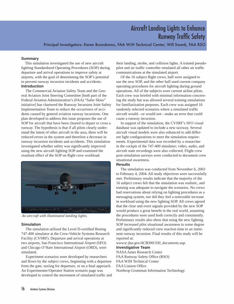
An aircraft with illuminated landing lights.

Aviation Systems Division 17
Joint Strike Fighter 2004Principal Investigators: Sibille Tallant, John Bessolo, Andrew Robbins, Eric Somers, and Paul Dobberstein,
Lockheed Martin Aeronautics
The experiment was performed over a three-week period in February and March of 2004, with each of the JSF variants having a one-week time slot. The CTOL researchers investigated conventional take-offs, landings, ground-handling, formation fl ying, and aerial refueling tasks. The CV researchers investigated both conventional and carrier-based landings and take-offs, and ground-han-dling tasks. Visual fl ight rules patterns and failure modes were tested for both the CTOL and CV confi gurations. The STOVL researchers investigated ship and shore vertical take-offs, recovery and landings, hover, and formation fl ying tasks. Many of the tasks were developed “on-the-fl y,” based on pilot comments and post-test analysis. Over forty representatives from various JSF contractor and Program Offi ce organizations participated in the motion runs in the VMS.
ResultsDuring the three-week study, eight pilots fl ew 1,362
data runs (CTOL:502 runs; CV:368 runs; STOVL:492 runs). Operations went smoothly and there was minimal down time. Post-simulation interviews revealed that both researchers and evaluation pilots were very pleased with the results. Commendations were given to SimLabs by all customer groups, both during and after the experiment.Investigative TeamBAE SystemsCorsair Training SystemsJoint Program Offi ceLockheed Martin AeronauticsUnited Kingdom Ministry of DefenseQinetiQNASA Ames Research CenterNorthrop Grumman Information Technology
SummaryThis simulation was the fi rst in a series of experiments
designed to evaluate the fl ight control system design and pilot-vehicle interface of the three different variants of the Joint Strike Fighter (JSF) aircraft: Conventional Take-Off & Landing (CTOL), Short Take-Off & Vertical Landing (STOVL), and Carrier Variant (CV).Introduction
The F-35 JSF will provide the US Air Force, Navy, and Marines with an affordable combat aircraft for the 21st cen-tury. Lockheed Martin was awarded the F-35 JSF contract in 2001 and is in the process of building the prototype of three JSF variant airframes. During the contract competi-tion, Lockheed Martin performed a series of simulations at NASA Ames Research Center and realized the importance of the unique motion capabilities of the Vertical Motion Simulator (VMS). In order to evaluate and enhance their fl ight control design and pilot-vehicle interface for the F-35, Lockheed Martin and the Joint Program Offi ce (US Air Force, US Navy, and US Marine Corps) conducted a series of experiments using the large VMS motion platform. Three variants of the JSF (CTOL, STOVL, and CV) were examined during this simulation.Simulation
To accommodate the complex JSF experiment require-ments, which included the integration of a large engine model supplied by the researchers, the VMS simulation host computer was upgraded to a faster processor, and an additional computer was added as an attached processor to run the engine model. The hardware interface was also upgraded to interface with the researcher-supplied con-trol inceptors. Additionally, the real-time host computer system software was extensively modifi ed to support the additional processor and the researcher-supplied software. New simulation software operational procedures were then devised to make it easier to accommodate the data sup-plied by the researchers.
The cockpit was built based on the layout specifi cation given by Lockheed Martin. All three variants tested in the study shared a common cockpit.
Three groups of researchers—one for each JSF vari-ant—participated in the simulation, and each group had different requirements and objectives. Therefore, the study was divided into three separate, but related, software con-fi gurations.
The F-35 JSF as depicted in the VMS.

18 Aviation Systems Division
FAA Obstacle ClearancePanel Simulation
Principal Investigators: Gerry McCartor, FAA Flight Operations Simulation & Analysis Branch; Mike Monroney, FAA Aeronautical Center; Bill Larsen, FAA NASA Ames;
Jerry Robinson, John Towler, and Gerald Whites, Boeing Commercial Airplane Group
Simulation Arrivals were conducted into John F. Kennedy Inter-national Airport runway 04R. A simulated local control-ler provided various calls to affect balked landings for the crews. Wave-off calls occurred at heights of 10, 20, 35, and 50 feet. Calls were assigned in a random manner according to a Latin Square design.
An Experimenter/Operator Station scenario page was created to provide researchers with a choice of simulated environmental variations during approach. Twelve distinct experimental conditions were available, made up of a combination of low and high steady wind; light and heavy aircraft weight; and low, medium, and high turbulence.
Thirteen pilots participated, each fl ying a series of 12 approaches with varying environmental conditions and two full-stop landings. To support the assessment of intra-pilot variability, each series was repeated four times for a total of 56 approaches. For each run, data collection began at 1,500 feet above ground level (AGL) and continued through 500 feet AGL for balked landings, or through 2000 feet after touchdown for completed landings. New software written by SimLabs personnel automated the data collection process. Aircraft position during balked land-ings—relative to the intended fl ight track—was recorded; audio and video data were also collected. Additionally, pilots completed pre-and post-fl ight questionnaires.Results
Seven hundred twenty-eight data runs were conducted between July 12 and August 6, 2004. Results are pending, but post-fl ight analysis of this data will evaluate the B747-400’s lateral and vertical dispersions during balked land-ings, relative to the intended fl ight path. Results from this study will assist the FAA and Boeing in the development of a mathematical pilot behavior model for the B747-400, which will ultimately aid the ICAO in efforts to develop pilot models for new large aircraft and determine appropri-ate OFZs.Investigative TeamFAA Flight Standards Aviation Laboratory BranchFAA NASA AmesBoeing Commercial Airplane GroupNASA Ames Research CenterNorthrop Grumman Information Technology
SummaryThis was the latest in a series of studies utilizing the
Crew-Vehicle Systems Research Facility’s (CVSRF) B747-400 simulator to examine large aircraft fl ight tracks and height loss arrest points as a result of balked landings. Collected data will be applied toward the development of a mathematical pilot model that will ultimately be used to determine required Obstacle Free Zones (OFZ) for new large aircraft.Introduction
The Federal Aviation Administration’s (FAA) “Airport Design Standards” Advisory Circular (No. 150/5300-13) prescribes runway design dimensions for various elements affecting runway utilization, including runway length, minimum safety areas, and adjacent taxiways for large aircraft. This Circular also mandates OFZ dimensions for airplanes with wingspans up to 262 feet; OFZs are neces-sary to provide safe conditions below landing decision height. This simulation supported an effort by the Inter-national Civil Aviation Organization (ICAO) to develop pilot models for use in determining OFZs for future large aircraft. Specifi cally, the ICAO is collecting data on pilot reaction during balked landing scenarios with the goal of developing a mathematical model of pilot behavior.
In support of the ICAO’s efforts, the FAA and Boeing utilized CVSRF’s B747-400 simulator in 1999 to examine pilot behavior during balked landings. The current study used the same simulator and gathered additional balked landing data under various environmental conditions for the construction and calibration of pilot models. To create the most accurate data set, both intra-pilot variation (vary-ing performance from occasion to occasion) and inter-pilot variation (difference between pilots) were investigated.
Data from this study will be used to develop a pilot model for new large aircraft, which will control the Flight Director model and aid in the determination of appropriate Obstacle Free Zones.

Aviation Systems Division 19
CH-47 Digital AdvancedFlight Control System
Principal Investigator: Chris Blanken, US Army
and restored existing simulation software developed at SimLabs for the ESD-model helicopter. They also devel-oped software for performing the various fl ight tasks, data collection, and statistical calculations, and for creating data displays in the lab. In addition, SimLabs developed software for the drive laws and real-time graphics for the symbology on the heads-down displays and the lab data displays.Results
The fi rst phase of piloted evaluations of the CH-47F DAFCS is complete. Three US Army experimental test pilots performed 417 formal evaluation runs on the VMS to assess the new DAFCS for both day and night opera-tions. Comparisons were made between two different mechanizations of the DAFCS and the legacy CH-47D analog FCS. Following consensus with the evaluation pilots, the results will be presented to the Army Program Offi ce and Boeing. Final VMS data collection will resume during October 2004, and fl ight tests will begin in March 2005.Investigative TeamUS ArmyNASA Ames Research Center Northrop Grumman Information Technology
SummaryThis simulation compared a new digital advanced fl ight
control system versus the standard analog fl ight control system during both daytime and nighttime operations of a CH-47 helicopter. Pilot performance and workload were evaluated.Introduction
The CH-47 Chinook helicopter is the US Army’s cargo-class helicopter. It was designed in the 1960s when the Army’s helicopters primarily operated in the day; now they operate mainly at night. The CH-47D uses the original analog fl ight control system (FCS), which has a rate-command response. Operating a rate-command response FCS at night results in degraded handling qualities which contributes to increased accidents.
To improve its handling qualities for nighttime opera-tions, the helicopter is being upgraded to the CH-47F, which will host two new digital computers as well as new electronic sensors, enabling the inclusion of a new digital advanced fl ight control system (DAFCS) designed by Boeing. The simulation at the Vertical Motion Simulator (VMS) compared pilot performance and workload using the DAFCS with that using the standard analog FCS.Simulation
The principal objectives of the simulation were to: assess the DAFCS to address control mode questions and design trade-offs prior to fl ight tests (i.e., to solidify the design of the control laws in an effort to reduce the number of fl ight test hours), compare pilot performance and work-load using the DAFCS with that using the standard analog FCS, and quantify the reduced visibility scene during night operations by determining its usable cue environ-ment rating. To conduct the evaluation, each pilot fl ew two different simulated helicopters to perform each of several fl ight tasks during both day and night conditions. For night operations, the pilots used night vision goggles. To meet the fi rst two objectives, pilots fl ew a simulated CH-47, and to meet the third objective, they fl ew a simulated generic helicopter that used an enhanced stability derivative (ESD) model.
To prepare for the simulation experiments, SimLabs’ personnel modifi ed, integrated, and checked out simula-tion software provided by Boeing for the CH-47 helicopter
A top-down view of the CH-47, as shown in the VMS.

20 Aviation Systems Division
There are many research areas thatbenefi t from aerospace simulation.
mSim airspace
operations
human performance
human interfacehuman interface
mission risk reductionsystem design
fl ight fl ight characteristicscharacteristics

Aviation Systems Division 21
Research-Directed Projects at SimLabs

22 Aviation Systems Division
Virtual Airspace Simulation Technology - Real- Time
Principal Investigators: Debbi Ballinger, NASA Ames Research Center;Ronald Lehmer, Northrop Grumman Information Technology
suite that is used to connect applications and facilities in a real-time simulation. Typically, HLA works by combining disparate simulation systems (“federates”) into a larger, common “federation,” where information is exchanged in real-time between federates using Run-Time Infrastructure (RTI) software. In the VAST-RT architecture, the HLA communications infrastructure is integrated with existing simulators using existing external interfaces where possible to minimize the cost and impact of connecting the simulators to the HLA federation.
The innovative interface design of VAST-RT allows for rapid and cost-effective integration of new and existing facilities, software models, and new ATC technology. The architecture and VAST-RT simulation components provide communications, control, and simulation support functions for widely distributed ATC simulations.
VAST-RT has completed a series of six Interim Tests (IT) and a V&V simulation. The simulations were conducted in multiple NASA Ames facilities, including FutureFlight Central (FFC), the Crew-Vehicle Systems Research Facility (CVSRF), and the Vertical Motion Simulator (VMS). ITs #1-4 were conducted during 2003, while the remaining tests and demonstrations occurred in 2004.
SummaryThe Virtual Airspace Simulation Technology-Real-
Time (VAST-RT) Project was established at NASA Ames Research Center as part of the Virtual Airspace Modeling and Simulation (VAMS) Project. The objective of VAST-RT is to provide new tools to simulate future air traffi c management technologies and techniques, with the ultimate goal of increasing National Airspace System (NAS) capacity, effi ciency, and safety. Through six interim test phases, culminating in a Verifi cation and Validation (V&V) simulation, VAST-RT has developed an environment that integrates multiple existing simulation facilities with ATC simulation components developed by VAST-RT. The distributed environment can provide a human-in-the-loop simulation using combinations of all ATC domains in the NAS. VAST-RT provides revolutionary capabilities to evaluate the human factors aspects of air traffi c management and control concepts, both system-wide and in localized segments of the NAS.Introduction
Air transportation continues to grow at an unprecedented rate due to increasing demand for air travel and shipping. Without further advancements in air traffi c management (ATM) and air traffi c control (ATC), the NAS will not be able to safely meet rising air transportation requirements. In 2000, NASA—in partnership with the Federal Aviation Administration (FAA), academia, and industry—created the VAMS project to address this problem. The Virtual Airspace Simulation Technologies (VAST) part of the project is responsible for providing a simulation and modeling environment for testing and evaluating the new ATM/ATC concepts developed within VAMS.
The VAST Project encompasses both real-time and non-real-time simulation. The Airspace Concept Evaluation System (ACES) is the non-real-time simulation tool and focuses on modeling broad, system-level operational concepts. VAST-RT simulates gate-to-gate, real-time, human-in-the-loop scenarios and provides a customizable framework for connecting low- and medium-fi delity real-time components with high-fi delity human-in-the-loop facilities in a distributed simulation environment.
The VAST-RT architecture is the “backbone” that links the simulation together. It relies on High Level Architecture (HLA), a Department of Defense software
View from the FFC control tower. Because of HLA bridging technology, multiple simulators can participate in the same scenario in real-time.

Aviation Systems Division 23
After the completion of the V&V simulation, VAST-RT Capability One was released. Capability One is operational software and is available to the VAMS Project and other customers for their use. Several components of Capability One are also available as source code from the VAMS Project. Simulation
The performance of the VAST-RT environment was measured quantitatively and qualitatively during the tests described below. Quantitative assessments were made of system and network loading, operational stability, and data integrity. Qualitative measurements of displays and usability were also made.
IT #5: The fi fth test validated three subsystems of VAST-RT, including initial delivery of the VAST-RT portal to the system interface and Airspace Operations Laboratory (AOL), FFC bridge enhancements for transfer of target control, and the VAST-RT User Interface Toolbox. The IT #5 simulation consisted of a Distributed Air/Ground scenario of south-fl ow traffi c on the east side of Dallas/Fort Worth (DFW) and included arriving and departing fl ights at DFW, as simulated by the FFC federate. This simulation successfully demonstrated ownership transfer between the VAST-RT federation and the FFC federate.
IT #6: The fi nal IT involved tests on network bandwidth, data compatibility, visual alignment, data collection capability, and reliability. This test incorporated a high-fi delity, en route airspace simulator in the simulation and demonstrated a gate-to-gate simulation between DFW and Chicago O’Hare International Airport (ORD).
Verifi cation and Validation: Verifi cation of the VAST-RT environment was accomplished using a simulation integrating CVSRF, FFC, AOL, the Airspace Target Generator, and other VAST-RT simulation control and support components located at the VMS complex. The simulation included fl ights arriving and departing from DFW and ORD, and all the airspace in between. The V&V demonstrated the successful implementation of a distributed simulation that included medium- and low-fi delity simulation components with existing high-fi delity human-in-the-loop simulation facilities. VAST-RT performance and data were analyzed by a human factors researcher and validated for use in experimental research.Results
The capability of the VAST-RT system to simulate large segments of the NAS in real-time and utilize multiple simulation facilities was successfully demonstrated. The conclusion of this portion of VAST-RT marked the achievement of a VAMS milestone with the delivery of Capability One. Preparations for Capability Two and testing of VAMS concepts are already underway.Investigative TeamNASA Ames Research CenterNorthrop Grumman Information Technology
Ames’ Airspace Operations Lab was incorporated into the VAST-RT architecture during IT #6.
The VAST-RT team won a NASA Honor Award in 2004 for their accomplishments on the project.

24 Aviation Systems Division
Lunar Lander Module Demonstrationat the Vertical Motion Simulator
Project Lead: Kathleen Starmer, Northrop Grumman Information Technology
fi eld of view to that experienced by Apollo astronauts. Sidestick controllers for thrust and attitude/translational control—comparable to those found in the actual LLM—were placed on both sides of each pilot seat.
A visual database of the lunar surface was developed using scanned photographs, and crater models were added to create additional topography. A visual model of the LLM itself was constructed to provide an observer’s view of simulations in progress to outside viewers. Head-down displays were created to mimic critical instrumentation present in the Apollo LLM. Additional displays, including a moving-map guidance system, were created to make the landing task easier for pilots and to showcase the VMS’ in-house software capabilities.Results All components of the simulation were successfully integrated, VMS motion was tuned, and the simulation was ready to fl y four weeks after the project began. Ames test pilots and an astronaut provided valuable improvements and feedback during the checkout period. Numerous visi-tors have fl own the LLM simulation, including astronauts and Space Exploration personnel from NASA Headquar-ters, and the feedback has been very positive. By imple-menting the LLM simulation, VMS personnel proved that the VMS is a valuable, capable asset, with the fl exibility to rise to new challenges in NASA’s revitalized Space Exploration program.Investigative TeamNASA Ames Research Center Northrop Grumman Information Technology
SummaryThe Lunar Lander Module (LLM) project was a proof-
of-concept simulation, demonstrating that the Vertical Motion Simulator (VMS) can be used to simulate vehicles beyond those found in traditional aeronautics. SimLabs’ simulation expertise and effi ciency allowed the project to be developed in just four weeks.Introduction
In January 2004, the President announced his Space Initiative, and a new era of space exploration was born. The Initiative calls for the development of a Crew Explo-ration Vehicle (CEV), and with its full-motion system and customizable infrastructure, the VMS is perfectly suited to participate in the design process. However, since the VMS has historically been used for development of vehicles fl ying in Earth’s atmosphere, VMS personnel decided to create a proof-of-concept demonstration, showcasing the facility’s ability to simulate vehicles beyond those found in traditional aeronautics. Because the actual design for the CEV is undetermined, VMS personnel simulated a previ-ously constructed space vehicle so as not to advocate a particular CEV model. The chosen vehicle was the Apollo LLM. Project Description The Space Initiative timeline is short, with the fi rst CEV fl ight test scheduled for 2008. With this in mind, VMS personnel determined that the LLM simulation should be shown to NASA Space Exploration personnel as early as possible. Thus, an important criterion was an extremely rapid development time. Additionally, since this was an unsponsored project, it was decided that material expendi-tures be kept to a minimum.
Developers obtained actual Apollo LLM fl ight manu-als and created a math model to closely approximate LLM behavior. An autopilot function was added so that visi-tors could experience an “autopilot failure” scenario in which they would have to take over the vehicle’s controls to effect a safe landing on the lunar surface. Modeling allowed for a vehicle that would respond as if it were oper-ating in the lunar environment (one-sixth of Earth’s gravity and no atmosphere).
Due to the rapid development time, it was determined that pilots would operate the LLM in a seated position rather than the standing position actually used in the Apollo program; this alleviated the need to crew-rate a novel confi guration. Windows were constructed to the exact dimensions of the Apollo LLM and placed over the cab’s out-the-window (OTW) screens to create a similar
Interior of a VMS cab, confi gured for the Lunar Lander Module simulation. The lunar surface is visible through the Apollo-style triangular windows.

Aviation Systems Division 25
Mars Database Developmentat FutureFlight Central
Project Lead: Boris Rabin, NASA Ames Research Center
One of the main diffi culties in optimizing the model was the large number of segments produced by the Viz software. On average, a 360-degree panorama is com-prised of more than 120 tiles with a texture map associated with each tile. In order to reduce the number of polygons, each segment required manual processing and entailed over 50 labor-hours of tedious effort. The turn-around time to produce a usable panorama was less than acceptable. Thus, this project focused on fi nding the set of parameters that would allow reduction of the polygon count, with-out compromising the fi delity of the database, thereby enabling smooth 30 Hz navigation through the scene.
To accomplish this, FFC engineers developed a conver-sion process to perform polygon reduction and photo-texture color enhancement in a batch mode. This reduced processing time to about 15-20 minutes per panorama, which is a far more useable timeframe.Results
Viewing the Eagle crater in 360 degrees and navigating through it in 3D provides scientists with a new level of situational awareness. It opens the possibility for integrat-ing rover autonomy software in FutureFlight Central with human workfl ow simulation. It also creates a potential for distributed simulation with existing Jet Propulsion Labora-tory rover simulation facilities. The integrated simula-tions could be exercised on single-rover, multi-rover, and human-plus-rover scenarios.
During this project it was demonstrated that a combi-nation of 3D modeling, image processing expertise, and FutureFlight Central’s unique visualization capability could support NASA’s long-term robotic surface explora-tion missions. Immersive visualization and environment simulation will be particularly relevant where signifi cant communications delays will be encountered.
Investigative TeamNASA Ames Research CenterNorthrop Grumman Information Technology
SummaryVisualization of the Mars Exploration Rover (MER)
image data in FutureFlight Central (FFC) using 2D, 3D and stereo formats was developed as a proof-of-concept demonstration intended to illustrate the potential of utiliz-ing FFC for planetary surface mission operations. This capability could broaden the scope of research within the Aerospace Simulation Operations Branch to include plan-etary surface science and remote robotic operations.Introduction
Recent robotic Mars missions represent an emerging vision within NASA of intensive planetary exploration within our solar system. One of the enabling technologies is the use of remotely operated intelligent mechanisms.
A primary challenge for remote mission scientists however, will be the immediate and continuous situational understanding of a rover in a distant environment. Because the number of command cycles during missions such as Mars Exploration Rover (MER) 2004 is limited due to transmission delays, it is important to maximize the sci-ence return potential of each commanded operation. One way to gain this effi ciency is to analyze and refi ne robot operations offl ine before sending a command sequence to the rover. The objective of this project, therefore, was to develop a high-fi delity simulation environment for science operations planning, as well as tools and visualization techniques for science analysis and terrain exploration. This was accomplished by leveraging FFC’s advanced 360º display system and powerful Image Generator in con-junction with surface reconstruction software developed at Ames by the Autonomy and Robotics Area (ARA) in Code IC.Project Description
In order to evaluate robot operations offl ine, a set of tools and visualization techniques were needed for the rapid development and optimization of a 3D Mars ter-rain model. Viz software, developed by ARA, was heav-ily utilized by scientists during the MER 2004 missions. A number of 3D models from the Spirit and Opportunity sites were generated from 2D stereo pairs. These models proved to be invaluable tools for scientists to explore in more detail the spatial characteristics and geological fea-tures of the terrain. For smooth navigation through the vir-tual Mars environment, however, a real-time, 30 Hz frame rate is required, which is impossible without optimization of the model.
The Mars 3D database, textured.

26 Aviation Systems Division
Voice CommunicationSystem Upgrade
Project Lead: Dan Wilkins, Northrop Grumman Information Technology
The third phase incorporated a full and open competi-tive procurement effort to replace the FFC VCS. The replacement VCS meets the needs of the VAST-RT project as well as enhancing several site-specifi c capabilities at FFC. The new VCS provides all-digital voice communica-tions for radio, intercom, dial-up emulation, direct connect, station-to-station, and record/playback. This VCS also supports both DIS and HLA standard network-based voice communication protocols along with multiple simultane-ous simulation operations. Record/playback capacity has been increased from 10 analog to 32 digital streams with event capture and upward growth capability. A user-defi n-able Graphical User Interface has been implemented to provide enhanced fl exibility of the VCS setup at each user station.
In parallel with the FFC upgrade, a number of signifi -cant improvements were made to the existing CVSRF VCS. First, several new radio models were created and standardized using best Original Equipment Manufacturer practices. Additionally, HLA and IP-multicast network protocols were implemented to compliment the existing DIS VCS. Lastly, a Voice over Internet Protocol bridge was created to integrate external facilities’ VCS with the CVSRF system. Results
The FFC VCS is undergoing fi nal testing and has been used to support VAST-RT efforts as well as site-specifi c operations and demonstrations. The remaining phases of this task include upgrading and replacing the CVSRF and VMS VCS systems, and work is in progress. The results of the team’s efforts have enhanced SimLabs’ voice commu-nications capabilities and benefi ted the VAST-RT Project. Investigative TeamSymphonicsNASA Ames Research Center Northrop Grumman Information Technology
SummaryThe purpose of the Voice Communication System
(VCS) upgrade project is to enhance the network-based voice communication capabilities for SimLabs at NASA Ames Research Center in support of VAST-RT concept development (see page 22 of this report). Introduction
Each of the SimLabs laboratories–FutureFlight Cen-tral (FFC), the Vertical Motion Simulator (VMS), and the Crew-Vehicle Systems Research Facility (CVSRF)–incor-porate localized voice communication capabilities to meet site-specifi c needs. The VAST-RT development effort called for a common set of network-based voice commu-nication capabilities across all SimLabs sites to meet inte-grated operational demonstration objectives. This, in turn, required HLA (High Level Architecture)-based aircraft radio communication, administrative intercom, and dial-up emulation over local (LAN) and wide area (WAN) digital networks. A method of capturing digital voice communica-tions for event-based record/playback and archiving was also required. Project Description
A project team was formed to evaluate existing VCS capabilities across all SimLabs sites and develop a stra-tegic approach for upgrading or replacing localized voice communication systems while maintaining current opera-tional capabilities in support of existing simulations.
Initial assessment of the facilities revealed that both the VMS and CVSRF sites supported DIS (Distributed Inter-active Simulation) standard network VCS for radio com-munication only; intercom communications were accom-plished using site-specifi c analog systems, and dial-up emulation did not exist at either site. Record/playback was analog only and did not provide event logging. Conversely, the FFC site incorporated a proprietary, closed-network VCS that supported only local radio communications, intercom, and dial-up emulation along with limited analog record/playback functionality.
The team then conducted an industry survey of voice communication technologies. Based on the fi ndings, a multi-phased approach was proposed. The fi rst phase con-nected the proprietary FFC VCS network to DIS standard protocol. This was accomplished by creating an analog-to-digital bridge with existing hardware and software. The second phase consisted of acquiring and integrating a commercial off-the-shelf DIS/HLA bridge solution to upgrade the DIS-networked VCS to an HLA radio voice communication standard. This system was successfully implemented to support the VAST-RT interim tests.
The Symphonics set-up panel.

Aviation Systems Division 27
High Level ArchitectureEnhancements at FutureFlight Central
Project Lead: Joe Mastroieni, Northrop Grumman Information Technology
a mechanism to allow the OHM to initiate transfer of MaxSim-owned targets to other federates for departures.
NASA directed the testing, and NGIT provided support. In particular, NGIT engineers responsible for the VAST-RT FFC bridge and the OHM components provided detailed troubleshooting during the comprehensive on-site testing and debugging of the MaxSim enhancements, working closely with the Adacel engineers.
The upgraded MaxSim software was initially installed in December 2003. Adacel provided an on-site engineer to assist in the installation and conduct initial testing. Further testing and debugging was conducted in January 2004 with the Adacel engineer on-site. Functionality of the enhance-ment was demonstrated, and the software was successfully used for VAST-RT Interim Tests 5 and 6, as well as the Verifi cation and Validation simulation.Results
The HLA portion of the FFC operational software was successfully enhanced to support the transfer of ownership capability. The ability of the system to handoff and transfer virtual aircraft to other domains in a distributed simulation environment was demonstrated three times during VAST-RT simulations, and the associated VAST-RT project requirements were met. The new enhancement enables FFC to fully participate as a key facility in future VAST-RT simulations. With the addition of FFC, VAST-RT pro-vides a new airspace modeling and simulation capability to evaluate revolutionary Air Traffi c Management concepts across all segments of the National Airspace System.Investigative TeamAdacel NASA Ames Research CenterNorthrop Grumman Information Technology
SummaryThis project enhanced the FutureFlight Central (FFC)
operational software, enabling it to participate in the VAST-RT Project development and future projects using the VAST-RT infrastructure. The upgrade was accom-plished in time to support VAST-RT Interim Tests #5 and #6, as well as the Verifi cation and Validation simulation.Introduction
The goal of the VAST-RT project is to develop a gate-to-gate, real-time, human-in-the-loop distributed simula-tion environment to evaluate concepts for improving the safety and effectiveness of the National Airspace System (refer to page 22 for more details). The VAST-RT archi-tecture is based on a High Level Architecture (HLA), a common framework allowing for data transfer and control between simulation components during real-time opera-tions of distributed simulations.
FFC is a critical resource in the VAST-RT project, serving as the air traffi c control tower simulator federate required in most simulations. The core FFC operating soft-ware included an HLA implementation that allowed it to act as a federate and participate in distributed simulations, but it did not incorporate ownership transfer, which allows a federate to divest or acquire ownership of an object (typi-cally an aircraft) under certain conditions. In particular, the VAST-RT project needed FFC to have the ability to trans-fer ownership of aircraft coming into or out of simulated FFC tower air space during VAST-RT experiments. Project Description
The operational software used at FFC is a propri-etary system from Adacel called MaxSim. As such, the upgrade project was a collaboration involving NASA, Adacel, and Northrop Grumman Information Technology (NGIT). NASA and NGIT determined the requirements and specifi cations for the upgrade to support the transfer of ownership function and provided the Statement of Work. NASA provided the Acceptance Test Procedures and test scenarios used to determine the software’s adherence to the requirements. NGIT provided the contract vehicle for the design, installation, and testing support tasks to be accomplished by Adacel, and also provided key technical support. Adacel designed and implemented the enhance-ment to the operational software.
The enhancement needed to retain all functionality of the existing software and operate on both the FFC tower and development systems. Adacel implemented a mecha-nism to allow the Ownership Handoff Manager (OHM), a component of the VAST-RT system, to initiate transfer of arrivals to MaxSim ownership. They also implemented
An air traffi c controller in FFC.

28 Aviation Systems Division
For additional information, please contact:
Tom AldereteAssistant Division Chief for Simulation Facilities
Aviation Systems Division(650) 604-3271
or
Barry SullivanBranch Chief
Aerospace Simulation Operations Aviation Systems Division
(650) [email protected]
About the back cover
A High Level Architecture (HLA) integrates all the SimLabs facilities and allows them to concurrently participate in distributed simulations. The image on the back cover depicts the Kennedy Space Center Shuttle Landing Facility from
FutureFlight Central’s database collection and shows the Space Shuttle landing during a real-time simulation occuring in tandem with the Vertical Motion
Simulator. The Crew-Vehicle Systems Research Facility could tie in to this simulation, as well, as suggested by the 757 aircraft.
In addition to traditional aeronautics, SimLabs is expanding to meet the challenges posed by the Nation’s Exploration Vision. FutureFlight Central has created a 3-D database using the latest Mars Rover images, and the Vertical Motion Simulator developed a conceptual Lunar Lander simulation based on
metrics from the Apollo program. Both of these projects are represented by the space view presented at the top of image.