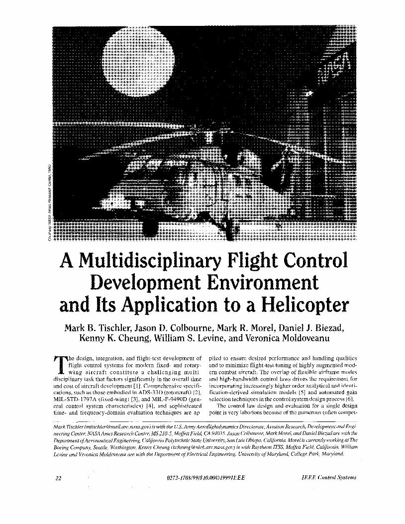
nasa arc 1999 multidisciplinary flight control development environment
DESCRIPTION
Mark Tischler ([email protected] is with the US. Army Aeroflightdynamics Directorate, Aviation Research, Development and EngineeringCenter, NASA Ames Research Center, MS210-5, Moffett Field, CA 94035. Jason Colbourne, Mark Morel, and Daniel Biezadare with theDepartment ofAeronautica1 Engineering, California Polytechnic State University, San Luis Obispo, California. Morel is currently working at TheBoeing Company, Seattle, Washington.K enny Cheung (kcheung@ nick.arc.nasa.gov)i s with Raytheon I T S , Moffett Field, California. WilliamLevine and Veronica Moldoveanu are with the Department of Electrical Engineering, University of Maryland, College Park, Maryland.TRANSCRIPT
ler? Jason I). ~ o l ~ Q ~ r ~ e , ~ a r ~ R. Morel, lliam S. Levine, and Vero~ica
he design, integration, and flight-test development of flight control systems for modern fixed- and rotary- wing aircraf t const i tute a chal lenging multi-
disciplinary task that factors significantly in the overall time and cost of aircraft development [ 11. Comprehensive specifi- cations, such as those embodied in ADS-33D (rotorcraft) [2], MIL-STD-1797A (fixed-wing) [3], and MIL-F-9490D (gen- eral control system characteristics) [4], and sophisticated time- and frequency-domain evaluation techniques are ap-
plied to ensure desired performance and handling qualities and to minimize flight-test tuning of highly augmented mod- ern combat aircraft. The overlap of flexible airframe modes and high-bandwidth control laws drives the requirement for incorporating increasingly higher order analytical and identi- fication-derived simulation models [5] and automated gain selection techniques in the control system design process [6].
The control law design and evaluation for a single design point is very laborious because of the numerous (often compet-
Mark Tischler ([email protected] is with the U S . Army Aeroflightdynamics Directorate, Aviation Research, Development and Engi- neering Center, NASA Ames Research Center, MS210-5, Moffett Field, CA 94035. Jason Colbourne, Mark Morel, and Daniel Biezadare with the Department ofAeronautica1 Engineering, California Polytechnic State University, San Luis Obispo, California. Morel is currently working at The Boeing Company, Seattle, Washington. Kenny Cheung (kcheung @nick.arc.nasa.gov) is with Raytheon I T S , Moffett Field, California. William Levine and Veronica Moldoveanu are with the Department of Electrical Engineering, University of Maryland, College Park, Maryland.
22 0212- 1108/99/$10.0001999IEEE IEEE Control Systems
ing) design specifications and constraints. This process must be repeated for the tens (or even hundreds) of configuration design points that are evaluated for a full flight envelope control systern. Further, the control system design engineer must continually up- date and integrate improvements in the mathematical models ;as hardware test data become available [ 11. Often, design specifica- tion changes are also introduced during aircraft development that, as with the other changes, require control law retuning across the flight envelope. Since current tools generally do not facilitate study of the tradeoffs between competing specifica- tions, hardware characteristics, and performance metrics, the fi- nal design may not make the best use of available control authority for modern high-performance, control-configured ve- hicles. The failure to consider such tradeoffs can compromise control system performance and handling qualities. Clearly, so- phisticated interactive computational tools are needed to inte- grate the many aspects of the flight control design process.
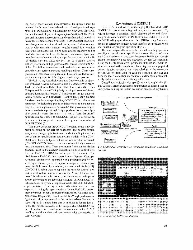
The U.S. Army Aeroflightdynamics Directorate, in conjunc- tion with NASA Ames Research Center, the University of Mary- land, the California Polytechnic State University (San Luis Obispo), and Raytheon ITSS, jointly developed a state-of-the-art computational facility for aircraft flight control design and evnl- uation referred to as CONDUIT (Control Designer’s Unifi’ed Interface). As the acronym implies, CONDUIT provides an en- vironment for design integration and data resource management (Fig. 1 ) . It is a sophisticated “associate” that provides compre- hensive analysis support and design guidance to a knowledge- able control system designer; it is not a “turn-the-crank” optimization program. The CONDUIT project is a follow-Ion from an earlier cooperative research program that developed GIFCORCODE 171.
This article describes the CONDUIT tool and a case study alp- plication based on the UH-60 helicopter. The control system analysis and design optimization methods, including the defini- tion of design specifications and system models within CON- DUIT and the multiobjective function optimization approach (CONSOL-OPTCAD) used to tune the selected design parame- ters, are presented first. Then a rotorcraft flight control design example based on the analysis and optimization of control laws for the RASCAL UH-60A helicopter is reviewed. The NASA/Army RASCAL (Rotorcraft Aircrew Systems Concepts Airborne Laboratory) is equipped with a programmable fly-by- wire flight control system to support a range of research pro- grams in flight control, simulation, and advanced displays [8]. CONDUIT is being used to evaluate the baseline control laws and control system hardware versus the ADS-33D specifica- tions. Then the selectable system gains are optimized to improve system performance and handling qualities. The CONDUIT re- sults are based on dynamic response models of the UH-60A heli- copter obtained from system identification, and thus are expected to be highly representative of actual RASCAL perf’or- mance without further significant modification. A second com- prehensive design study based on the X-29 high-performance fighter aircraft was presented in the original AIAA Conference paper [9] but is omitted here due to publication length limita- tions. The results presented in [9] suggest that CONDUIT can provide options for considerable improvement in the X-2’9A handling qualities and servo-loop characteristics compared to its current design.
Key Features of CONDUIT CONDUIT is built on top of the highly flexible MATLABI
SIMULINK system modeling and analysis environment [lo], which includes a graphical block diagram editor and block- diagram-to-code features. CONDUIT makes extensive use of the MATLAB graphical user interface (CUI) coding features to create an interactive graphical user interface for problem setup and pushbutton program operation (Fig. 2).
The user graphically selects the desired handling qualities and flight control system specifications from libraries of stan- dard fixed- and rotary-wing specifications or builds new specifi- cations from generic time- and frequency-domain specifications using the highly interactive Specmaker application. Specifica- tions are wired to the simulation block diagram via a graphical editor, thereby avoiding any manipulation of the extensive MATLAB “m” files used for each specification. The user can bend the specification boundary curves, and the system automat- ically updates the relevant defining spline data.
Compliance with all active specifications is graphically dis- played on the criteria with a single pushbutton command, signifi- cantly streamlining the system evaluation process. A key feature
I CONDUIT -Control Designer’s Unified hierface
p-
i
Fig. 1. CONDUIT control system integrution and design evaluation process.
Fig. 2. Collage of CONDUIT displays.
August 1999 23

of CONDUIT is that a single mouse click on any of the specifica- tions brings up an extensive set of supporting plots that present all the relevant analyses associated with the specification. A multiobjective function optimization environment (CONSOL- OPTCAD) [ 111 is integrated into CONDUIT to allow the user to tune selected design parameters (e.g., gains, time constants) for compliance with the active design specifications or to update control laws for changes in modeling data and design specifica- tions. If desired, the user can generate a gain schedule for the full flight envelope by optimizing the control system at each of the operating points or can determine a single gain set that satisfies the criteria for multiple flight conditions. An important applica- tion of the automated tuning capability is examining the trade- offs between control system performance and actuator authority requirements and between competing specifications. Finally, the CONDUIT problem definition and all results are stored and or- ganized by case name for easy retrieval and comparative studies by the user.
CONDUIT Evaluation and Design Process Overview
An appropriate control law loop architecture must be defined as part of the problem definition prior to running CONDUIT. CONDUIT can then be used to evaluate the baseline design and to tune the design parameters for best system behavior.
CONDUIT has two basic modes of operation: setup and run. In setup mode, the user accesses SIMULINK to define or import the simulation mathematical model and control law architecture. The aircraft response models are obtained from analytical simula- tions or system identification results derived from flighvground- test data. The main aspect of problem setup in CONDUIT is the graphical selection and wiring of the handling qualities and servo-loop specifications from the provided libraries (e.g., Fig. 3). Currently, there are six graphical libraries comprising more than 100 specifications in CONDUIT:
rotorcraft in hover/low-speed flight [2] rotorcraft in forward flight [2] fixed-wing lateral/directional characteristics [3], [ 121 fixed-wing longitudinal characteristics [ 3 ] , [ 121 Short Takeoff and Vertical Landing (STOVL) characteris-
general system characteristics [4] tics [I31 Fig. 3. Example window from the handling-quality specifi:cation
libraries. ~
QikRoH2:Quickness
(dphi)min [des] (a)
Fig. 4. (a ) Quickness spec including a IO% design margin; (b) Example ofsupporting plot that explains the results displayed on specif cation.
24 IEEE Control Systems

Three levels of compliance are defined for each specificatialn following the handling-qualities levels conventions [2], [3 I . In thLe Level I region (blue), the aircraft characteristics are “satisfactory without improvement,” and this is the desirable performance re- gion. The bordering region (magenta) is Level 2, “deficiencies warrant improvement.” This is the adequate performance region and may be acceptable under degraded system operations or for flight outside the design flight envelope. The final region (red), Level 3, “deficiencies require improvement,” is the inadequate performance region, where the mission task will be compromisedl.
The splines that define the boundaries between each level can be graphically altered to update the libraries with new specifica- tions or to evaluate the sensitivity of a design to changes in the cnL- teria. Additionally, CONDUIT accommodates the uncertainty in the simulation mathematical model and changes in actual flight condition relative to the reference condition by allowing the user to include a “design margin,” as illustrated in Fig. 4(a). Thus, in flight, the control system performance can degrade into this de- sign margin without entering the Level 2 region.
The user declares each specification to belong to one of the following five classes: hard constraint, soft constraint, perfor- mance objective criterion, summed objectives, or check spec only. The selection of specification class defines the solution strategy for the CONSOL-OPTCAD optimization process. Finally, the user must also set up a small initialization file to de- fine problem-dependent constants such as simulation time-step and test input signals.
In CONDUIT’S run mode, the user establishes starting values for the design parameters and conducts an initial evaluation of all the system specifications. Supporting analysis plots for eaclh specification can be examined for further insight into system be- havior and the effects of control system changes on specification compliance (Fig. 4(b)). The user can then tune the design param- eters manually with rapid access to all the linear and nonlinear response implications or can use the automated tuning feature to achieve Level 1 (“desirable region”) performance of all the spec- ifications. Finally, the optimization feature of CONDUIT can be exercised to tune the design parameters for best performance rel- ative to a selected set of objective criteria. For a typical aircraft control system design problem ( 5 to 10 design specifications, 3 to 5 design parameters, 10 to 15 states), the system can obtain an optimized solution in less than an hour on a Silicon Graphics workstation. However, depending on the complexity of the prob- lem, the computational time may increase significantly. For in- stance, the presented UH-60 problem, which has more than 70 states, 12 design parameters, and 31 constraints, takes approxi- mately 5 hours on the same SGI workstation to reach its opti- mized solution.
Design Tuning The uyer graphically selects design parameters that will be
used by CONDUIT in the tuning process. Typically, these are the feedback and feedforward parameters (e.g., gains, time con- stants) that are scheduled as a function of flight condition in modern fly-by-wire aircraft. CONDUIT feeds the design param- eters and constraints in the form of a “pseudo C” program file to the optimization engine, CONSOL-OPTCAD.
The theoretical basis for CONDUIT’S automated tuning function rests on the assumption that any individual specifica- tion can be adequately approximated by a smooth (at least twice
differentiable) function, mapping the design parameters into a real number. For example, if x_ E SZ c R”, where5 is the n-vector of parameters and L2 is the set of admissible parameter values, then (5) is the specification. The specification can be a perfor- mance criterion, meaning that the goal is to minimize J,’ (5) over all 5 E SZ, or it can be a constraint, meaning (g) I p, (pireal) in order for5 to be an admissible value for the design parameters.
The design problem, once fully formulated, will be solved iteratively starting from some initial guess, x,, for the design pa- rameters. For any constraint that is not satisfied at x, (e.g., &(&J > P I ) , an obvious way to proceed is to treat that constraint temporarily as a performance criterion and try to find an x_ that minimizes f , (g) subject to g E Q. In attempting to minimize A(&), the computer will either move to an x that satisfies &(g) 5 p j or show that no such solution exists. Thus, constraints and performance criteria are equivalent until a value of 5 that sat- isfies the constraints is found.
The previous paragraphs show that a typical design problem can be mathematically formulated as a constrained multi- criterion parametric optimization problem. In most such prob- lems, it is necessary to trade off among competing criteria. For example, in most control design problems, increasing the feed- back gain improves tracking but degrades gain margin. To use the computer to assist in solving such a design problem, the mul- tiple criteria must be reduced to a single criterion that captures these tradeoffs. It is well known that no weighted linear combi- nation of criteria can do this. Mathematically,
always occurs at an * (a) satisfying
minx(&) for some i, 1 I i 5 rn. (2) ztn
In other words, the value of 5 that minimizes any linear com- bination of performance criteria always equals the value of 5 that minimizes one of the criteria. This is illustrated in Fig. 5(a) for a simple problem involving two design specifications and one de- sign parameter. The weights can only change which specific cri- terion is optimized. All the others are ignored and no tradeoff occurs.
A good way to combine the multiple performance criteria so as to balance competing objectives is as follows:
( 3 )
The advantage of this formulation is that the optimal value of x_ can be placed anywhere in the region of the parameter space bounded by the minima of the individual criteria by appropriate choice of the a,. This is shown for the simple example in Fig. 5(b). Thus, any reasonable choice of the at produces a trade-off among the specifications. The CONDUIT distance algorithm automatically normalizes the weightings for the specifications using the natural choice of the width of the Level 2 regions. A de- signer could cxplore the tradeoffs by adjusting the relative widths of those regions.
The min/max formulation of (3) reduces the complex prob- lem of multiple design criteria to one of minimizing a scalar per-
August 1YYY 25

formance measure subject to constraints. However, solving even the scalar optimization problem is difficult, since the criteria val- ues {A(&)} are generally a highly nonlinear function of the design parameters (g). CONDUIT employs the CONSOL-OPTCAD [ 111 optimization engine to solve this difficult problem. As the iterative solution progresses and those J;@) that correspond to constraints become satisfied, they change from being perfor- mance criteria to being satisfied constraints. Conceptually, such satisfied constraints redefine Q. Thus, at each stage, CONSOL- OPTCAD is trying to solve a constrained parametric optimiza- tion problem. Feasible Sequential Quadratic Programming (FSQP) [14],[15] is the algorithm used by CONSOL-OPTCAD. It is the most attractive optimization approach currently known for solving such problems. The idea behind FSQP is to approxi- mate the original optimization problem by a sequence of qua- dratic programming problems. This approximation should result in quadratic convergence near the optimum. The word “feasible” refers to the fact that the solution continues to satisfy any con- straint at every iteration after the first one for which the con- straint is satisfied.
System optimization using CONSOL-OPTCAD is con- ducted in three distinct phases. In Phase 1, the design parameters are tuned to ensure that the “hard constraints” are satisfied; typi- cally, these are absolute stability (eigenvalues, for instance) or relative stability (gain and phase margin, for instance) in each loop and other Level 1 specifications that must be satisfied. Once all the hard constraints meet the Level 1 criteria, the optimization process moves into Phase 2 and begins to work on the “soft con- straints.”
Most of the problem’s specifications are declared as soft con- straints. This choice allows CONDUIT to accept a solution that does not strictly meet all the Level 1 requirements, but one that reaches the best possible compromise for the available actuator authority. If the design satisfies all the Level 1 requirements for the soft constraints, CONSOL-OPTCAD has achieved a “feasi- ble solution.” Since any design that resides in the Level 1 region is feasible, Phase 2 optimization actually reaches a “family” of design solutions. Now the optimization process enters Phase 3.
In Phase 3, CONSOL-OPTCAD will tune the design parame- ters to optimize the system to the selected performance criteria and thereby select a final “best design” from the family of feasi- ble solutions. Two commonly used performance criteria for con- trol system optimization are actuator energy and feedback-loop crossover frequency. Minimizing these parameters will ensure that the Level 1 design specifications are achieved with the mini- mum use of control authority and minimum sensitivity to sensor noise. Here, it is often useful to employ the summed objective formulation of (l), since the users are generally trying to drive down the actuator energy across multiple loops and at the same time achieve minimum broken-loop crossover frequency. By de- fining the specifications as summed objectives instead of indi- vidual objectives, the user allows the optimization engine to explore a broad space of possibilities to optimize performance.
Control system hardware parameters, criteria splines, and de- sign margins can be systematically adjusted to quickly retune the design and generate tradeoff curves. By conducting a tradeoff study to trace the variation of the performance criteria with the de- sign margins, the aircraft designer can evaluate the sensitivity of the required actuator performance to changes in the aircraft agility and maneuverability requirements. Even moderate relaxation in
the criteria can allow the use of a significantly reduced actuator bandwidth, thereby reducing weight and thus lowering cost.
Rotorcraft Control Law Design Study Problem Setup
In this design study, CONDUIT is used to analyze and tune the baseline control system for the RASCAL UH-GOA fly-by- wire research helicopter [SI (Fig. 6). The RASCAL control law architecture is based on the explicit model-following Advanced Digital Optical Control System (ADOCS) [ 161. The schematic block diagram of Fig. 7 illustrates the important system ele- ments. The block marked “Command Model” ( M ) contains the desired dynamic response characteristics, typically represented by low-order transfer functions. The block marked “Aircraft Dy- namics” ( P ) is a 14-degree-of-freedom linear state-space repre- sentation of the multi-inputlmulti-output UH-60 bare airframe dynamics and precompensation to improve dynamic decoupling [ 171. The aircraft dynamics model was extracted from flight-test data using the CIFER package [18], an advanced fre-
Fig. 5. (a ) Linear combination ofpe$ormance criteria; ( b ) Midmax solution approach used in CONSOL-OPTCAD.
26 IEEE Control Systems

quency-domain system identification procedure specifically de- veloped for the rotorcraft problem [ 191. Inputs to the helicopter are via the main rotor swashplate for pitch, roll, and vertical con- trol and the tail rotor pitch for yaw control. The vertical loop is not closed in this study because the open-loop dynamics in this axis are well damped and already meet the relevant han- dling-quaJities requirements. The block marked “inverse plant model” (F’) contains the inverses of low-order transfer function approximations of P. If the inverse plant model is accurate, the aircraft will track the desired “Command Model” (M) response with very low bandwidth feedback compensation (H). The feed- back compensation (H) contains the feedback gains and com- pensators for ensuring stability, robustness, and disturbance rejection and suppressing any error arising from incomplete can- cellation by the plant inverse.
The complete SIMULINK schematic of the RASCAL system is shown in Fig. 8. The design parameters consist of nine feed- back gains and three command model parameters. The three command model parameters directly set the desired speed of commanded response for the pitch, roll, and yaw channels. The handling-quality specifications for this study are obtained from ADS-33D [2]. Feedback-loop specifications are also included to ensure adequate levels of stability and robustness and to mini- mize control actuator saturation. The nine feedback gains are composed of three gains (proportional, integral, and rate) for each of the pitch, roll, and yaw channels. The “hard constraints” selected for this problem were gain and phase margin require- ments for the feedback loops and minimum stable real part for all closed-loop eigenvalues. Bandwidth, quickness, coupling, actu- ator saturation, and wind gust rejection specifications from
Plant Approximation
Fig. 6. The RASCAL UH-60 helicopter.
Dynamics Command
Model
-+ Inverse Aircraft
Fig. 7. Model-following block diagram.
August 1999
ADS-33D [2] were all defined as “soft constraints.” The perfor- mance criteria selected were the summed objectives of actuator energy and feedback-loop crossover frequency for each of the three loops ($/e in Fig. 7).
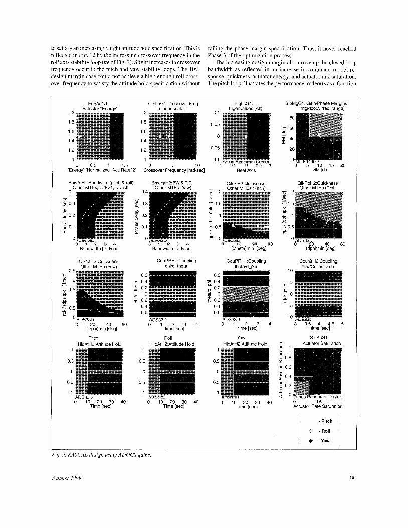
Baseline and Optimized Design Performance The performance of the baseline RASCAL system design is
shown on the CONDUIT specification window in Fig. 9. The baseline design meets the Level 1 criteria except for the yaw bandwidth, the pitch, roll, and yaw quickness, and attitude hold in yaw. CONDUIT successfully tuned the design to reach a “fea- sible solution” that achieved all hard and soft constraints. The Phase 3 optimized design shown in Fig. 10 also minimizes the se- lected performance criteria and meets Level 1 requirements for all specifications. Note that both figures are the actual presenta- tion of the results in the CONDUIT handling-quality window. The first seven characters in each of the specification title (EngAcG1, for instance) represents the “nickname” of the corre- sponding specification in CONDUIT. The axes of each specifi- cation are labeled based on their units as described in the ADS-33D documentation [2]. The text on the lower left corner of each specification describes its source origin.
Table 1 compares the design parameter values for the opti- mized solution with those for the baseline system. The baseline design does not use integral feedback loops; therefore, the gains for these loops are set to zero for the baseline design. One notice- able change for the optimized design is the increase in the roll and yaw command model frequency parameters ( M m and M V ) so the associated quickness and bandwidth specifications could be met:
L- - M,”
Ocmd (s + M , I* (4)
whereO,$, andv represent pitch, roll, and yaw, respectively. The subscripts represent the model response (mod) and the command of the given axis (cmd).
The increase in command model parameters causes increased actuator activity shown on the actuator energy and saturation specifications. Fig. 11 shows the supporting plots for the yaw quickness and yaw actuator energy specifications. The figures show that the yaw angle and yaw rate responses are smooth and do not possess any unwanted oscillations. The associated actua- tor position and rate responses (Fig. l l(b)) provide a complete picture of the system performance.
The Table 1 comparison also shows a large reduction in the roll rate and yaw rate gains, which resulted in the considerable reduction in associated crossover frequencies achieved by CON- DUIT Phase 3 optimization. There is an attendant reduction in roll and yaw channel phase margins. Further Phase 3 reductions in crossover frequency are restricted by the wind gust rejection response, which was relaxed to the Level 1Level2 border in all
27

I)rsiqr7 Hasoline uprimi:cil piruint'wr /.'If I t L'I i0,l \u l i ie iir CONDUIT
I . .
15.7
9.0
- . Pitch proportional gain 13.6
. -.. ' Roll proportional gain 8.0 K6
Kv Yaw proportional pain 7.6 7.4 . . .
. . . . . . . . . . . . . . . . . . . . . . . . . . . . .
6.5 , a 71--_ -. . Kq Pitch rate gain 6.1
Roll rate gain 2.1
Yam' ratt gain 3.2 1 . 1
.. . I . . I KP
~
Kr . .
0.38 .-
K 10 Pitch integral gain 0
KIq, Roll intcgral pain 0 0.48
Yaw integral gain 0 0.03
Pitch command niodel frequency 2.0 1.2 Me
hl, Roll conimand modcl frcqiicncy 2.5 4.3
Yaw command niodel frequency 3.0 3.1 WJ
... .. - .. -. -. ..... ... .......
.....
. .- . ._ i K'W . . . .
- ~ .........
..... -.______ ....... .... -
~- .. . . . . . .. .~ -.
three channels. Further reduction in the control en- ergy usage is limited by the pitch, roll, and yaw quickness specifications, which have points resting on the Level l/Level 2 borders for small attitude changes.
Tradeoff Studies As depicted in Fig. 4(a), CONDUIT allows a de-
sign margin to be added to specifications. The de- sign margin enforces overdesign to ensure that acceptable solutions lie a set distance into the Level 1 region and not on the Level 112 border. This builds in design robustness. For example, a 10% design margin would set the acceptable border 10% of the width of the Level 2 region into the Level 1 region, as shown in Fig. 4(a).
The tradeoff between design margin and control system performance was examined using CON- DUIT. For this study, design margins of 0%, 2S%, 5%, 7.5%, and 10% were included in the previous RASCAL model-following design example. The starting design parameters for the system were the baseline RASCAL control laws described in the previous section.
CONDUIT reached satisfactory solutions for in- creasing design margin from 0% through 7.5%. As the design margin was increased, the required feed- back loop gains also grew, especially in the roll axis,
Fig. 8. SIMULINK diagram of the RASCAL model-following control laws.
28 IEEE Control Systems
to satisfy an increasingly tight attitude hold specification. This is reflected in Fig. 12 by the increasing crossover frequency in the roll axis stability loop (fk of Fig. 7). Slight increases in crossover frequency occur in the pitch and yaw stability loops. The 10% design margin case could not achieve a high enough roll cross- over frequency to satisfy the attitude hold specification without
failing the phase margin specification. Thus, it never reached Phase 3 of the optimization process.
The increasing design margin also drove up the closed-loop bandwidth as reflected in an increase in command model re- sponse, quickness, actuator energy, and actuator rate saturation. The pitch loop illustrates the performance tradeoffs as a function
EngAcGl : CrsLnG1 :Crossover Freq. EigLcGl : Actuator "Energy" (linear scale) ^ . Eigenvalues (All)
StbMgGl : Gain/Phase Margins (rigidbody freq. range)
2
1 8
1 6
1 4
1 2
1 0 0 5 1 1 5 0 5 10 1 0 5 0 0 5 1
Energy [Norrnalizeo Acr RateA2] Crossover Frequency [rad, sec] Real AXIS 0 5 10 15 20
GM [ob]
BnwAtH1 :Bandwith (pitch & roll) Other MTEs;UCE>I; Div Att
BnwYaH2:BW & T.D. Other MTEs (Yaw)
QikPiH2:Quickness - Other MTEs (Pitch) QikRoH2:Quickness Other MTEs (Roll)
0 4
8 0 3
a, 0 2
- U
- x
0 a, 2 0 1 a
0 0 1 2 3 4 0 1 2 3 4 0 10 20 30 0 20 40 60
Bandwidth [radkec] Bandwidth [rad/sec]
CouPRHl :Coupling phi/d-theta
(dtheta)min [des] (dphi)min [deg]
QikYaH2:Quickness Other MTEs (Yaw)
CouPRHl :Coupling thetdd-phi
CouYaH2:Coupling Yaw/Collective b
0 6 - 0 2
0 0 0 2
- m 04-
L
O 6 - ADS33D
0 6 - 0 20 40 60
(dpsi)min [deg]
Pitch HldAtH2:Attitude Hold
0 1 2 3 4 time [sec]
Roll HldAtH2:Attitude Hold
0 1 2 3 4 time [sec]
3 3.5 4 4.5 time [sec]
5
Yaw HldAtH2:Attitude Hold
SatAcG1 : Actuator Saturation
1
0 5
0
0 5
1 ADS'3Q.D ADS33D . .- - - - - 0 10 20 30 40
Time (sec) 0 10 20 30 40
Time (sec) 0 10 20 30 40
Time (sec) 0 0.5 1 Actuator Rate Saturation
- Roll
+ -Yaw
Fig. 9. RASCAL design using ADOCS guins.
August 1YYY 29

of design margin (Fig. 13). The command model for pitch is given in (4). Increasing the design margin drives up the quick- ness (Fig. 13(a)). This requires a faster command model, which is generated by increasing M O (Fig. 13(b)). Increasing M , results in a higher bandwidth (Fig. 13(c)), which causes more actuator activity, shown by actuator energy (Fig. 13(d)), and more rate saturation of the actuator (Fig. 13(e)).
With the steep rise in the curves in Figs. 13(d) and 13(e), there will obviously be a large penalty in terms of actuator en- ergy and rate saturation for small increases in design margin above 7.5%. Thus, the 7.5% margin probably represents the best design point for the case, with the 10% margin represent- ing the ultimate limit due to the earlier phase margin restric- tions. Rozak [21] has shown that increased actuator activity due
EngAcGl : CrsLnG1 :Crossover Freq. EigLcG1 : - Actuator "Energy" (linear scale) Eigenvalues (All)
StbMgGl: Gain/Phase Margins (rigidbody freq. range)
". ' Ames Research Center 0 0.5 1 1.5 0 5 10 "Energy" [Normalized-Act. Rate21 Crossover Frequency [rad/sec] ' 0'5 Real Axis 0'5
BnwAtH1:Bandwith (pitch & roll) BnwYaH2:BW &T.D. Other MTEs;UCE>l; Div Att ^ . Other MTEs (Yaw)
QikPiH2:Quickness - Other MTEs (Pitch)
Bandwidth [rad/sec]
QikYaH2:Quickness Other MTEs (Yaw)
0 20 40 60 (dpsi)min [degl - -
Pitch HldAtH2:Attitude Hold
1
0.5
0
0.5
1 ADS33D 0 10 20 30 40
Time (sec)
0 1 2 3 4 Bandwidth [rad/sec]
CouPRHl :Coupling phi/d-theta
ADS33D 0 1 2 3 4
time [sec]
Roll HldAtH2:Attitude Hold
ADS33D 0 10 20 30 40
Time (sec)
CouPRHl :Coupling thetafd-phi
0 6 - E 0 2
O 4 B O 6 -
ADS33D 0 1 2 3 4
time[secr
Yaw HldAtH2:Attitude Hold
0 10 20 30 40 Time (sec)
. . . . -. . . . . - 0 5 10 15 20
GM [db]
QikRoH2:Quickness Other MTEs (Roll) . ,
0 20 40 60 (dphi)min [deg]
CouYaH2:Coupling Yaw/Collective b
3 3.5 4 4.5 5 time [sec]
SatAcG1: - Actuator Saturation
2 " Ames Research Center 0 0.5 1 Actuator Rate Saturation
T -Roll
-Yaw
Fig. 10. Optimized RASCAL design.
30 IEEE Control Systems

Input Signal 0.9
.... .......
...........
.......
0.3
0.2
...... ...... .......
Time [sec]
Psi Response 60
.....
.......
"0 2 4 6 Time [sec]
(a)
..... ..... ..... ..... ..... .....
..... ..... ..... ..... ....
0.08 ..... ..... .... ..... ..... .... ....
0.06 ..... ..... .....
0.04 ..... ..... .... ..... ..... ..........
0.02 ..... ..... ..... .... ..... ................
'0 0.5 1 1.5 2 2.5 3 3.5 4 4.5 Time [sec]
Maximum Rate = 1.524 - Minimum Rate = 2.402 $ 6 ._ 5 4
8 , $ 2
c .- W O 2
I 5 4
9 5 6
Time [sec]
r Response
Time [sec]
Maximum Position = 0.4512 Minimum Position = 0.2315
.....; .....; .....; ....; .....; .....
..... ..... I . . . ........
.....
0'30 0.5 1 1.5 2 2.5 3 3.5 4 4.5 5 Time [sec]
Half "Energy" = 0.05956 i. w [Normalized_Rat&2]
'0 0.5 1 1.5 2 2.5 3 3.5 4 4.5 5 Time [sec]
Fig. 11. (a ) Supporting plots for (a ) the yaw quickness and (b) actuator energy specifcations.
to overdesign leads to shorter fatigue life of the pitch horn (ro- tor control) structures.
Future Development Plan Currently, one limitation of CONDUIT is that the system is
only capable of evaluating and optimizing the given control sys- tem on a per-aircraft-configuration basis. Thus, in order to pro- duce a gain schedule for multiple flight conditions, CONDUIT requires the user to set up and analyze an individual problem for each condition. To facilitate such a time-consuming process, a batch mode processing functionality and a databasing capability will be developed. Such functionality will allow the user to feed spreadsheets of flight conditions into the system for evaluations and optimizations. The results will then be stored by cases into the database for later retrieval and further comparative analysis.
August 1999
A sensitivity tool, which provides the user more detailed graphic information on the correlation of the design parameters in the optimization pro- cess, is also in the development phase.
Availability CONDUIT is currently being made available
to U.S. Government agencies and U.S. Govern- ment agency contractors under one-year Cooper- ative Research and Development Agreements (CRDA).
Summary CONDUIT, a new computational facility for
aircraft flight control design and evaluation, has been developed and demonstrated. CONDUIT offers a graphical environment for integrating simulation models and control law architectures with design specifications and constraints. This tool provides comprehensive analysis support and design guidance to a knowledgeable control system designer. Combining the easy-to-use graphical interface, the preprogrammed libraries of specifications, and the multiobjective function optimization engine (CONSOL-OPTCAD) in a single environment, CONDUIT offers the poten- tial for significant reduction in time and cost of design, analysis, and flight-test optimization of modern flight control systems.
A case study application to a complex ro- tary-wing flight control problem was presented. The baseline RASCAL UH-60 control system, as provided by the flight control contractor, was evaluated versus the ADS-33D handling-quality specifications. The selectable system gains were optimized to meet all system performance and handling-quality specifications. CONDUIT suc- cessfully exploited the tradeoff between forward loop and feedback dynamics to significantly im- prove the expected handling qualities and stabil- ity robustness, while reducing crossover frequency and minimizing actuator activity.
The tradeoff studies showed the effect of in- creasing design margin (overdesign) on closed- loop performance and actuator activity. Design
margins exceeding 7.5% led to rapidly increasing actuator energy and saturation, resulting in shortened fatigue life of rotor control
Fig. 12. Crossover frequency as a function of design margin.
31

-~
Fig. 13 (a ) Pitch quickness as a function of design margin; (b) Pitch command model frequency Me as a function of design margin; ( c ) Pitch bandwidth as a function of design margin; (d ) Pitch actuator energy as a function of design margin; ( e ) Pitch actuator saturation as afunction of design margin.
structures. A solution that met thelo% design margin could not be found. These results show that the ADS-33 rotorcraft specifica- tions tightly constrain the UH-60 design problem, leaving less than a 10% margin for increased performance.
References [I] M.B. Tischler (Editor),Advances in Aircraft Flight Control, Bristol, PA.: Taylor and Francis Ltd., 1996.
[2] United States Army Aviation Systems Command, “Handling Qualities Requirements for Military Rotorcraft,” ADS-33D, St. Louis, MO, 1996
[3] United States Department of Defense, “Flying Qualities of Piloted Vehi- cles,” MIL-STD-1797, 1987.
[4] United States Department of Defense, Military Specification, Flight Con- trol Systems-General Specifications for Design, Installation, and Test of Piloted Aircraft, MIL-F-9490D, 1975.
[5] M.B. Tischler, “System Identification Requirements for High- Bandwidth Rotorcraft Flight Control System Design,” J. Guidance, Control, andDynamics, vol. 13, no. 5, pp. 835-841, 1990.
[6] M.D. Takahashi, “Rotor-State Feedback in the Design of Flight Control Laws for a Hovering Helicopter,” J. American Helicopter Society, vol. 39, no. 1, pp. 52-62, 1994.
[7] G. Yudilevitch, M.B. Tischler, W.S. Levine, and C. Lin, “Rotorcraft Flight Control System Design Based on Multi-Criterion Parametric Opti- mization,” AIAA Guidance, Naviga- tion, and Control Conference, Baltimore, MD, August 7-9, 1995.
[8] E. Aiken, R. Jacobsen, M. Eshow, W. Hindson, and D. Doane, “Prelimi- nary Design Features of the RAS- CAL-A NASA/Army Rotorcraft In-Flight Simulator,” AIAA Paper 92-41 75, August 1992.
[9] M.B. Tischler, J.D. Colbourne, M.R. Morel, D.J. Biezad, W.S. Le- vine, and v . Moldoveanu, “CON- DUIT-A New Multidisciplinary Integration Environment for Flight Control Development,” AIAA Pa- per 97-3773, August 1997.
[lo] MATLAB(@): High-Performance Numeric Computation and Visnaliza- tion Software, The Mathworks, Inc., Reference Guide, 1992.
[ 111 CONSOL-OPTCADTM User’s Manual (Version 1.2-1.5, Released May 1992), University of Maryland, College Park, MD, 1992.
[12] D.G. Mitchell, and R.H. Hoh, “Proposed Incorporation of Mission- Oriented Flying Qualities into MIL-
tober 1994.
[13] J.A. Franklin and M.W. Stortz, “Moving Base Simulation Evaluation of Translational Rate Command Sys- tems for STOVL Aircraft in Hover,” NASA TM-110399, June 1996.
STD 1797A,” WL-TR-94-3162, OC-
[ 141 E.R. Panier, and A.L. Tits, “On Combining Feasibility, De- scent, and Superlinear Convergence in Equality Constrained Opti- mization,” Mathematical Programming, vol. 59, pp. 261-276, 1993.
[15] C. Lawrence, J.L. Zhou, and A.L. Tits, “User’s Guide for CFSQP Version 2.4: A C Code for Solving (Large Scale) Constrained Nonlin- ear (Minimax) Optimization Problems, Generating Iterates Satisfying All Inequality Constraints,” University of Maryland, College Park, MD, 1996.
[16] S.I. Glusman, C. Dabundo, and K.H. Landis, “Evaluation of ADOCS Demonstrator Handling Qualities,” Proc. 43rd Annual Na- tional Forum ofthe American Helicopter Society, Washington, D.C., May 1987.
[17] D.R. Catapang, M.B. Tischler, and D.J. Biezad, “Robust Crossfeed Design for Hovering Rotorcraft,” Int. J. Robust and Nonlinear Control, vol. 4, no. 1,1994.
[ 181 M.B. Tischler and M.G. Cauffman, “Frequency-Response Method for Rotorcraft System Identification: Flight Applications to BO-105 Coupled RotodFuselage Dynamics,” J. American Helicopter Society, vol. 37, no. 3, pp. 3-17, 1992.
[ 191 J.W. Fletcher, “Identification of UH-60 Stability Derivative Models in Hover from Flight Test Data,” J. American Helicopter Society, vol. 40, no. 1, pp. 32-46, 1995.
”^ IEEE Control Systems
1201 M B Tixhler, J W FletLhcr, P M Patrick, M Morris, and G E Tucker, “Flying Quality Analy\i\ dnd Flight Evaluation of d Highly Augmented Combat Rotorcraft,” I Guidance, Control, andDjnamicr, vol 14, no. 5 ,pp 954-963, 199 I
[211 J N Rorak dnd A Rdy, “Robo\t Multivariable Control of Rotorcraft in
Forward Flight Impact of Bmdwidth on Fatigue Life,” J American Hell- coptet Societv, vol 43, no 3, pp 195-201, 1998.
ster Engineering Corp ds a Consulting Engineer from 1995 to 1997 Hejoined Sterling Software in April 1997 and Rdytheon ITSS in 1998 as d Pnncipal Software En- gineer While at both Sterling and Raytheon, he partici- pated as the software lead on the CONDUIT project at NASA Ames Research Center.
Mark B. Tischler ha\ been at the Ames Research Cen ter since 1983, where he currcntlj \erves as Flight Cou- trol Group Leader in the Army/NASA Rotorcraft Division, leading research activities in rotorcraft flight control, system identification and simulation Dr Tischlei has authored or Lo-duthored over 50 technical pdper\ and reports, and has won numerous awards from the U S Army and NASA for his work in rotorcraft flight dynamics and control He wds the organizing edi- to author the recently published book Advance? in Aii-
Daniel J. Biezad is currently a Profesor in the Aero- space Engineering Depatment at California Polytech- nic State University, San Luis Obispo, and has over 4,000 hours of flight experience i n both fixed-wing and rotorcraft, including pilot instructor duties at the USAF Test Pilot School He alvo has been an Air Force test en- gineer lor remotely piloted vehicles and missiles He is an Associate Fellow of the AIAA, a Senior Member of the IEEE, and a member of Eta Kappa Nu. Dr Biezad
tedches and does research in the area of piloted flight control and simuldtion He hds authored a book published in 1999 by the AIAA titled IntenrutedNuv-
ctaft Flight Control (TdyIor and Francis)
Jason D. Colbourne received his M S in Aerondutical Engineering trom California Polytechnic State Univer- sity, San Luis Obispo, in 1997 and a bachelor’s degree in Aerospace Engineering from San Diego State Uni- versity in 1993 Mr Colbourne has worked d\ d con- trdcting research engineer in the Army/NASA Rotorcraft Divi\ion dt Ames Research Center since 1995
Mark R. Morel received his B.S in Aeronautical Engi- ncering from Clarkson University in 1995 while working as an engineering assistant at NASA Dryden Flight Re- sedrch Center He received his M S m Aeronauticdl En- gineering from Cdlifornia Polytechnic State University ( 1 997) while working at NASA Ames Research Center He is currently d Flying Qudhties and Simulation Engi- neer for Boeing Military Aircraft and Misvles Systems Group and i s working on the Joint Strike Fighter Project
Kenny K. Cheung received his M S in Aerospace Engineering from the De- pdrtment af Aeronautics and Astrondutics dt Stanford University In 1995 He received his B S in both Aeronautical and Mechdnicdl Engineering from University of Cdhfornld-DdviS i n 1993 He then worked for Stone and Web-
igation urzd Guidance Sjstems
William S. Levine is currently a Professor of Electrical Engineenng at the University of Maryland at College Park His man research interests are in techniques for the design of control systems and in the analysis of biomechanical signdls dnd control systems Dr Levine is d Fellow of the IEEE and a Distinguished Member of the IEEE Control Systems Society. He is presently an Associdte Editor at Large of the ZEEE Trunructzons on Automatic Control He hds been President of the IEEE
Control Systems Society He is the editor of The Control Hundbook pnb- lished by CRC Press in cooperation with the IEEE.
Veronica Moldoveanu received her B.S. in Electrical Engineering from “Politehnica” University of Bucha- rest, Romania, in 1992 and her M S in Electrical Engi- neering from the University of Maryland at College Park, College Park, MD, in 1998. Ms. Moldoveanu is interested in computer-aided control-system design, optimization theory, system modeling, simulation, and software development.
August 29YY 33