nasa osma nde program additive manufacturing foundational ... · reentrant ti6-4 tube for a...
TRANSCRIPT

Jess Waller (NASA WSTF), James Walker (NASA MSFC), Eric Burke, (NASA LaRC), Douglas Wells (NASA MSFC), Charles Nichols (NASA WSTF)
National Aeronautics and Space Administration - Office of Safety and Mission Assurance
Approved for public release
NASA QUALITY ASSURANCE IN ADDITIVE MANUFACTURING (AM)
A WORKSHOP ON ASSURING AM PRODUCT INTEGRITYOctober 11-12, 2016
Beckman Auditorium, California Institute of Technology, Pasadena CA
NASA OSMA NDE Program
Additive Manufacturing Foundational Effort
https://ntrs.nasa.gov/search.jsp?R=20160011480 2020-03-23T07:12:04+00:00Z

2Collaboration: NASA and non-NASA Players
Background• NASA is providing key leadership in an international effort
linking NASA and non-NASA resources to speed adoption of additive manufacturing (AM) to meet NASA’s mission goals. Participants include industry, NASA’s space partners, other government agencies, standards organizations and academia:
• Nondestructive Evaluation (NDE) is identified as a universal need for all aspects of additive manufacturing

3
Background
NASA/TM-2014-218560 NDE of AM State-of-the-Discipline Report
Contacts: Jess Waller (WSTF); James
Walker (MSFC); Eric Burke (LaRC)• NASA Agency additive
manufacturing efforts were
catalogued
• Industry, government and academia
were asked to share their NDE
experience in additive manufacturing
• NIST and USAF additive
manufacturing roadmap were
surveyed and a technology gap
analysis performed
• NDE state-of-the-discipline was
documented

NASA Agency & Prime Contractor Activity
Reentrant Ti6-4 tube for a
cryogenic thermal switch for the
ASTRO-H Adiabatic
Demagnetization Refrigerator
Inconel Pogo-Z baffle for RS-25
engine for SLS
Aerojet Rocketdyne RL-10 engine
thrust chamber assembly and injector
Prototype titanium to niobium gradient rocket nozzle
EBF3 wire-fed system during
parabolic fight testing
4
28-element Inconel 625 fuel
injector
SpaceX SuperDraco combustion
chamber for Dragon V2ISRU regolith structures
Made in Space AMF on ISS
Dynetics/Aerojet Rocketdyne
F-1B gas generator injector
4

5
NDE of AM Technology Gaps
NASA/TM-2014-218560 Recommendations & Technology Gap Analysis
• Develop in-process NDE to improve feedback control, maximize part
quality and consistency, and obtain ready-for-use certified parts
• Develop post-process NDE of finished parts
• Develop voluntary consensus standards for NDE of AM parts
• Develop better physics-based process models using and corroborated
by NDE
• Use NDE to understand scatter in design allowables database
generation activities (process-structure-property correlation)
• Fabricate AM physical reference samples to demonstrate NDE
capability for specific defect types
• Apply NDE to understand effect-of-defect, and establish acceptance
limits for specific defect types and defect sizes
• Develop NDE-based qualification and certification protocols for flight
hardware (screen out critical defects)

6
Develop and Capture
Best NDE Practice

7
NDE of AM Technology Gaps
NASA/TM-2014-218560 Recommendations & Technology Gap Analysis
• Develop in-process NDE to improve feedback control, maximize part
quality and consistency, and obtain ready-for-use certified parts
• Develop post-process NDE of finished parts
• Develop voluntary consensus standards for NDE of AM parts
• Develop better physics-based process models using and corroborated
by NDE
• Use NDE to understand scatter in design allowables database
generation activities (process-structure-property correlation)
• Fabricate AM physical reference samples to demonstrate NDE
capability for specific defect types
• Apply NDE to understand effect-of-defect, and establish acceptance
limits for specific defect types and defect sizes
• Develop NDE-based qualification and certification protocols for flight
hardware (screen out critical defects)

NDE-based AM Part Qualification & Certification
post-process
NDE
post-process
NDT
in-process
NDE
7

9United States and International AM Standardization Efforts
ASTM WK47031, NDE of metal parts used in aerospace applications (NASA leadership)
ISO TC 261 JG59 Best NDE Practice
• First defect catalogues to show defect NDE linkage• Process method determines defects• Defect type & part complexity determine NDE selection
ASTM E07.10 WK47031 NDE of AM Guide

10
ASTM WK47031 Collaboration Area
49 current members
10
NASA, JAXA, ESA, NIST, USAF, GE Aviation, Boeing, Lockheed, Aerojet Rocketdyne, Honeywell, ULA and various AM and NDE community participants are represented

11
ASTM WK47031 Round Robin Testing
Coordinated by S. James (Aerojet Rocketdyne)
11
Inconel 625 on copper
Ti-6Al-4V (4)
Electron Beam Freeform Fabrication (EBF3)
SS 316
Al 2216
Selective Laser Melting (SLM)
Ti-6Al-4V bars Al-Si-10Mg dog bones SS 316 PT/RT panels w/ EDM notches
Electron Beam Melting(EBM)
Inconel 718 inserts (6)w/ different processing history
Inconel 718 prisms for CT capability demonstration
Characterized to date by various NDE techniques (CT, RT, PT, PCRT, and UT)

12
Identify Relevant Defects

13ISO TC 261 JG59 Best NDE Practice § Process Method Determines Defect Type
Background
§ISO TC 261 JG59, Additive manufacturing – General principles – Nondestructive evaluation of additive manufactured products,
under development.
Note: DED = Directed Energy Deposition., PBF = Powder Bed Fusion
Develop
new
NDE
methods
While certain AM flaws
(e.g., voids and porosity)
can be characterized
using existing standards
for welded or cast parts,
other AM flaws (layer,
cross layer,
unconsolidated and
trapped powder) are
unique to AM
and new NDE
methods are
needed.

14Typical PBF Defects of Interest
Also have unconsolidated powder, lack of geometrical accuracy/steps
in the part, reduced mechanical properties, inclusions, gas porosity,
voids, and poor or rough surface finish
Trapped PowderLayer
Cross layer

15Typical PBF and DED Defects
DED Porosity
Also interested in (gas) porosity and voids due to structural implications
PBF Porosity
Note: proposed new definitions in ISO/ASTM 52900 Terminology:lack of fusion (LOF) nflaws caused by incomplete melting and cohesion between the deposited metal and previously deposited metal.
gas porosity, nflaws formed during processing or subsequent post-processing that remain in the metal after it has cooled. Gas porosity occurs because most metals have dissolved gas in
the melt which comes out of solution upon cooling to form empty pockets in the solidified material. Gas porosity on the surface can interfere with or preclude certain NDT methods, while
porosity inside the part reduces strength in its vicinity. Like voids, gas porosity causes a part to be less than fully dense.
voids, n flaws created during the build process that are empty or filled with partially or wholly un-sintered or un-fused powder or wire creating pockets. Voids are distinct from gas
porosity, and are the result of lack of fusion and skipped layers parallel or perpendicular to the build direction. Voids occurring at a sufficient quantity, size and distribution inside a part can
reduce its strength in their vicinity. Voids are also distinct from intentionally added open cells that reduce weight. Like gas porosity, voids cause a part to be less than fully dense.
Voids
Univ of Louisville
ConceptLaser
Plastic
Porosity and Voids
SLM Solutions
ISO TC 261 ISO TC 261

16
Demonstrate NDE Capability

17
NDE of AM Technology Gaps
NASA/TM-2014-218560 Recommendations & Gap Analysis
• Develop in-process NDE to improve feedback control, maximize part
quality and consistency, and obtain ready-for-use certified parts
• Develop post-process NDE of finished parts
• Develop voluntary consensus standards for NDE of AM parts
• Develop better physics-based process models using and corroborated
by NDE
• Use NDE to understand scatter in design allowables database
generation activities (process-structure-property correlation)
• Fabricate AM physical reference samples to demonstrate NDE
capability for specific defect types
• Apply NDE to understand effect-of-defect, and establish acceptance
limits for specific defect types and defect sizes
• Develop NDE-based qualification and certification protocols for flight
hardware (screen out critical defects)

18
Demonstrate NDE capability
Conceptual Physical Reference Samples

19
Demonstrate NDE capability
Actual and Planned NASA Physical Reference Samples for Additive Manufacturing

20
Understand Effect-of-Defect

21
NDE of AM Technology Gaps
NASA/TM-2014-218560 Recommendations & Gap Analysis
• Develop in-process NDE to improve feedback control, maximize part
quality and consistency, and obtain ready-for-use certified parts
• Develop post-process NDE of finished parts
• Develop voluntary consensus standards for NDE of AM parts
• Develop better physics-based process models using and corroborated
by NDE
• Use NDE to understand scatter in design allowables database
generation activities (process-structure-property correlation)
• Fabricate AM physical reference samples to demonstrate NDE
capability for specific defect types
• Apply NDE to understand effect-of-defect, and establish acceptance
limits for specific defect types and defect sizes
• Develop NDE-based qualification and certification protocols for flight
hardware (screen out critical defects)

22
Determine effect-of-defect on sacrificial specimens with
seeded flaws
Sacrificial Effect-of-Defect Standards
Advratech Laser PBF samples
(in progress)
Ti-6Al-4V ASTM E8 compliant dogbones for in situ OM/IR
and post-process profilometry, CT and PCRT
AlSi10Mg ASTM E8 compliant dogbones
13mmØ, 85mm long (6mmØ, 30mm Gauge Length)
Airbus Laser Powder Bed Fusion
(PBF) samples
Investigate effect post-processing on
microstructure and surface finish on
fatigue properties
§FY17 STTR T12.04-9941 Real-Time Geometric Analysis of Additive Manufacturing status
(NASA MSFC) Develops a novel process control and part documentation solution for selective laser
melting (SLM) additive manufacturing (DECLINED).
FY17 STTR T12.04-9979 Metal Digital Direct Manufacturing (MDDM) for Close-Out of Combustion
Chambers and Nozzle Fabrications. Sub-scale and intermediate size nozzles will be fabricated using
hybrid MDDM processes and delivered to the NASA-MSFC for hot fire testing (APPROVED)

23
Qualify & Certify NASA
AM Hardware

24
NDE of AM Technology Gaps
NASA/TM-2014-218560 Recommendations & Gap Analysis
• Develop in-process NDE to improve feedback control, maximize part
quality and consistency, and obtain ready-for-use certified parts
• Develop post-process NDE of finished parts
• Develop voluntary consensus standards for NDE of AM parts
• Develop better physics-based process models using and corroborated
by NDE
• Use NDE to understand scatter in design allowables database
generation activities (process-structure-property correlation)
• Fabricate AM physical reference samples to demonstrate NDE
capability for specific defect types
• Apply NDE to understand effect-of-defect, and establish acceptance
limits for specific defect types and defect sizes
• Develop NDE-based qualification and certification protocols for flight
hardware (screen out critical defects)

25
Background
Qualification & Certification/NASA MSFC Guidance
Contact: Doug Wells (MSFC)• Comprehensive draft technical
standard is in review
• All Class A and B parts are expected
to receive comprehensive NDE for
surface and volumetric defects
within the limitations of technique
and part geometry
• Not clear that defect sizes from
NASA-STD-5009§ are applicable to
AM hardware
• NDE procedural details
are still emerging§
NASA-STD-5009, Nondestructive Evaluation Requirements for
Fracture-Critical Metallic Components

26
Background
Qualification & Certification/NASA MSFC Guidance
§ NASA classifications should not to be confused with those used in the ASTM International standards for AM parts, such as F3055
Standard Specification for Additive Manufacturing Nickel Alloy (UNS N07718) with Powder Bed Fusion. The ASTM classes are
used to represent part processing only and are unrelated.
Comprehensive
NDE required
for surface and
volumetric
defects

27
Qualification & Certification
NASA MSFC Guidance
• It is incumbent upon the structural assessment community to
define critical initial flaw sizes (CIFS) for the AM part to
define the objectives of the NDE.
• Knowledge of the CIFS for AM parts will allow the NDE and
fracture control communities to evaluate risks and make
recommendations regarding the acceptability of risk.
• CIFS defects shall be detected at the accepted probability of
detection (POD), e.g., 90/95, for fracture critical applications.
• Demonstration of adequate part life starting from NASA-
STD-5009 flaw sizes is generally inappropriate for fracture
critical, damage tolerant AM parts.
• It is recognized that parts with high AM Risk may have regions
inaccessible to NDE. To understand these risks it is important
to identify the inaccessible region along with the CIFS.

28
Qualification & Certification
NASA MSFC Guidance
• Parts with low AM risk should exhibit much greater coverage for
reliable NDE.
• Multiple NDE techniques may be required to achieve full coverage.
• Surface inspection techniques (PT, ECT, UT) may require the as-
built surface be improved to render a successful inspection,
depending upon the defect sizes of interest and the S/N ratio.
• For PT, surfaces improved using machining, for example, require
etching prior to inspection to remove smeared metal. • Removal of the as-built AM surface to a level of visually smooth may be insufficient
to reduce the NDE noise floor due to near-surface porosity and boundary artifacts.
• NDE demonstration parts with simulated CIFS defects are used to
demonstrate NDE detection capability.
• NDE standard defect classes for welds and castings welding or
casting defect quality standards will generally not be applicable

29
Qualification & Certification
NASA MSFC Guidance
• Relevant AM process defect types used must be considered.
• AM processes tend to prohibit volumetric defects with significant
height in the build (Z) direction. The concern instead is for planar
defects, such as aligned or chained porosity or even laminar cracks,
that form along the build plane. The implications of this are: − planar defects are well suited for growth
− planar defects generally have low contained volume
− the orientation of defects of concern must known before inspection,
especially when detection sensitivity depends on the defect orientation
relative to the inspection direction
− the Z-height of planar defects can be demanding on incremental step
inspection methods such as CT
• Until an AM defects catalog and associated NDE detection
limits for AM defects are established, NDE acceptance criteria
shall be for part-specific point designs.

30
Determine Rejection Thresholds for
Critical Defects

Joint ASTM E07-E08-F42 (NDE-Fracture & Fatigue-AM) Round Table
Address:
• Fracture & fatigue of AM parts
• AM parts used in fracture
critical applications
• Critical flaw size for AM defects
Qual
& Cert
Fracture
MechanicsNDE
AM
31

32
Current NASA Efforts
Related to NDE of Additive
Manufacturing

33
FY16 Continuing Projects• An Assessment of NDE Capability and Materials Characterization for Complex Additive
Manufacturing Aerospace Components (Walker, Martin)
• Investigation of NDE Flaw Detectability in AM Parts (Koshti, Stanley, Taminger, Hafley,
Brice, Burke)
• X-ray Computed Tomography Image Quality Indicator Development (Jones, Fischetti, Kent)
• KSC Foundational Methodology for Additive Manuf. – Electron Beam Melting NDE (Skow)
• Evaluation of Additively Manufactured Metals for use in Oxygen Systems (Tylka)
• NDE of Aerospace Parts (including Additive Manufactured) Voluntary Consensus
Organization Standards and Related Round-Robin Tests (Waller, Nichols)
NASA OSMA NDE Program Foundational Methodology for Additive Manufacturing

34
FY17 New Starts
• A Quantitative Assessment of NDE
Capability on Additive Manufactured
(Selective Laser Melting) Inconel 718
(Walker, Martin)
NASA OSMA NDE Program Foundational Methodology for Additive Manufacturing
• Effect-of-Defect of Unique Laser Powder
Bed Fusion Flaw Types: NASA-Industry
Round Robin Study (Waller, Nichols)

35Additive Manufacturing Structural Integrity Initiative (AMSII)
• Involves the characterization of defect structures of selective laser melting (SLM) Inconel® 718 material within the nominal process window and its limits, build test articles for NDE studies and correlation with destructive test results
• Relevance to parts made for Commercial Crew Program (CCP), Space Launch System (SLS) and Multipurpose Crew Vehicle (MPCV)

36
America Makes/ANSI
Additive Manufacturing
Standardization Collaborative
(AMSC)

America Makes & ANSI Additive Manufacturing Standardization Collaborative (AMSC) 37

America Makes & ANSI Additive Manufacturing Standardization Collaborative (AMSC) 38
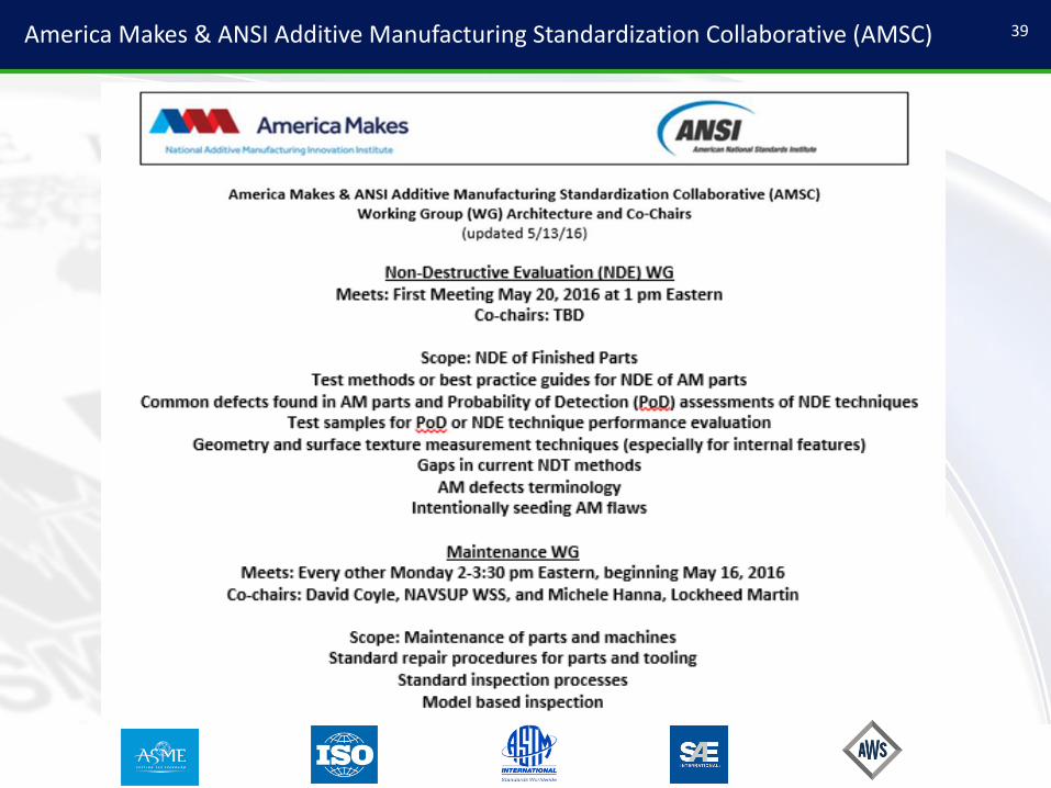
America Makes & ANSI Additive Manufacturing Standardization Collaborative (AMSC) 39

AMSC Nondestructive Evaluation Working Group Roadmap – 9/2/16 draft 40

AMSC Qualification and Certification Working Group Roadmap – 9/14/16 draft 41

42Questions?

43
Back-ups

44Key Documents Driving the Improved Safety and Reliability of AM Parts
NASA AM Foundational Effort
Technological Acceptance and
Increased Utilization

45NIST TRL Gap Analysis
NIST Roadmap Contact: Kevin Jurrens (NIST)• Technology challenges impede
widespread adoption of AM
• Measurement and monitoring
techniques, including NDE, cut
across all aspects of AM, from input
materials to processing to finished
parts
• Ways to fully characterize AM parts,
including NDE, are needed to insure
processing effectiveness and part
repeatability (part certification)
• NASA participationo Matt Showalter, GSFC
o Karen Taminger, LaRC
o Gary Wainwright, LaRC
o Nancy Tolliver, MSFC

46AFRL-RX-WP-TR-2014-0162 NDE of Complex Metallic AM Structures
Effect of Design Complexity on NDE
Contact: Evgueni Todorov (EWI)• Great initial handling of NDE of
AM parts
• Report has a ranking system
based on geometric complexity
of AM parts to direct NDE
efforts
• Early results on NDE application
to AM are documented
• Approach for future work based
on CT and PCRT

47ASTM WK47031 and AFRL-RX-WP-TR-2014-0162 NDE of Complex Metallic AM Parts
Effect of Design Complexity on NDEMost NDE techniques can be used for Complexity Groups§ 1 (Simple Tools and Components) and 2 (Optimized Standard Parts), some for Group 3 (Embedded Features); only Process Compensated Resonance Testing and Computed Tomography can be used for Groups 4 (Design-to-Constraint Parts) and 5 (Free-Form Lattice Structures):
1 2 3
4 5
§Kerbrat, O., Mognol, P., Hascoet, J. Y., Manufacturing Complexity Evaluation for Additive and Subtractive Processes: Application to Hybrid Modular
Tooling, IRCCyN, Nantes, France, pp. 519-530, September 10, 2008.

48AFRL-RX-WP-TR-2014-0162 AM Part Complexity Groups§ Drive NDE Selection
Background
§Kerbrat, O., Mognol, P., Hascoet, J. Y., Manufacturing Complexity Evaluation for Additive and Subtractive Processes: Application
to Hybrid Modular Tooling, IRCCyN, Nantes, France, pp. 519-530, September 10, 2008.
NDE options for
design-to-constraint
parts and lattice
structures: LT,
PCRT and CT/mCT