national radio astronomy observatory green bank, …
TRANSCRIPT

NATIONAL RADIO ASTRONOMY OBSERVATORYGreen Bank, West Virginia
Electronics Division Internal Report No 48
A SURVEY OF DELAY LINE TECHNIQUES
Leon M. Morrison
AUGUST 1965
NUMBER OF COPIES: 75

A SURVEY OF DELAY LINE TECHNIQUES
Leon M. Morrison
INTRODUCTION
A group of delay lines is required for the interferometer system. These
delays range from 1. 5 -- 3040 nanoseconds. The frequency range is from 2 - 12
MHz. At present these delays are achieved with coaxial cables, which take four
equipment racks to house.
A literature search was undertaken to determine whether a more suitable
arrangement could be found.
The delay system investigation was divided into ultrasonic delays, lumped
parameter networks, cables, magnetostrictive devices and yttrium-iron-garnet
solid state delays.
No attempt has been made to limit the discussion to delay devices which
meet the above specifications. Rather, a general search was made since there is
a possibility that the system requirements might change in the future.
ULTRASONICS
Ultrasonic delay lines consist basically of transmitting and receiving trans-
ducers separated by a delay medium which is typically Mercury (Hg) , water,
quartz, etc.
The input transducer has a signal impressed upon it which is converted into
an ultrasonic wave. This wave traverses a prescribed path and finally impinges
on a receiving transducer for conversion back into a usable signal. Thus the delay
is dependent upon the path length and the velocity of propagation in the medium.
Solid quartz lines are rapidly replacing both the Hg and water lines due to
their smaller size and lighter weight.
A typical quartz delay line consists of a quartz blank to .which two Y-cut
quartz crystals are fixed by Indium bonds. The main beam is collimated by coating
the edges of the reflecting facets with an absorbing material. This reduces
spurious responses in the medium. These delay lines are usually packed into a
hermetically sealed can which has been filled with an insulating material.

2
Figure 1 shows some typical quartz delay line shapes.
Some fairly typical characteristics of quartz aeiay lines using quartz trans-
ducers are:
Delay times ................................. 250-2000 psec
Carrier frequency .......................... 15-40 MHz
Bandwidths (= 1/2 carrier freq.) .... 7-20 MHz
Attenuation (a) 40-70 dB
Characteristic impedance ........... 75 C2
The insertion loss due to quartz transducers can be reduced by using
ceramic (barium titanate) transducers. The most serious difficulty is that a
ceramic transducer operating above 10 MHz must be extremely thin and therefore
is very brittle.
Some quartz delays using ceramic transducers have been built with a
1 millisecond delay and an insertion loss of 20 dB into 50 O. This was with a
6.7 MHz bandwidth and a center frequency of 18 MHz [1]. While these lines have
desirable characteristics, they are not practically feasible due to many technical
difficulties.
The trend in quartz delay lines is towards higher frequencies and larger
bandwidths. Ceramic and quartz transducers are limited in frequency range due
to the difficulties in handling the thin transducer plates which would be required
for higher frequencies.
Current research into the use of extrinsic piezoelectric semiconducting
materials as transducers promises to solve many of the difficulties now en-
countered [2]. The transducing region of the semiconductor is a thin, flat, high-
resistance depletion layer which can be generated on the surface of the semi-
conductor plate. An additional advantage is that this depletion layer thickeness
(and thus the transducer resonant frequency) can be varied over a very large
range by a DC biasing field. The frequency range of these transducers is from
near 300 MHz to perhaps greater than 10 GHz.

Some typical quartzdel„: line shapes.
Figure
out
in
o mt';'•
:13 4 540
/6 /8 20 22Freq. (MHz)
24
Figure 2. Performance of a 1 ms delay line shown above to illustratethe effect of impedance an bandwidth and insertion loss.

3
Further study of piezoelectric semiconductor m terials has led to the dis-
covery of direct amplification of ultrasonic energy in CdS crystals subjected to
certain conditions [3]. Gains of 18 dB' s at 15 MHz and 38 dB' s at 45 MHz have been
reported.
As was mentioned earlier in the report, w ter is sometimes used as the delay
medium. A typical delay line with water as delay medium will exhibit the following
characteristics [4]:
Delay time 000 0 . 0 0 0 0 0 110 25-55 pisec
Insertion loss ......00... a . 0 0 0 0 0 50-75 dB
Bandwidths will run as high as 10 MHz centered
as high as 30 MHz.
An interesting variation on quartz delay lines is the so-called "Photo-Elastic"
delay line. Fused quartz becomes birefringent (1 e. it will rotate the plane of
polarization of light passing through it) when subjected to strain [5]. Figure 3 shows
the application of this phenomena to delay lines.
As can be seen in Figure 3, a piezoelectric transducer is bonded to a quartz
bar, which is placed between crossed polarolds (or Nicols prisms).
A signal injected into the bar by the transducer will, upon passing the slits,
rotate the plane of polarization of the light p;. , ssing through and thus illuminate the
detector. The bandwidth is determined by the width of the slits relative to the signal
wavelength and also the orientation of the plane of polarization.
It is obvious that this method is well suited to either variable or multiple
tap delay lines since the detector is not in physic contact with the line itself.
Photoelastic delay lines have been built by Comings with up to 150 micro-
seconds delay at frequencies up to 30 MHz.
An interesting property of this type of delay is that if two quartz bars with
their polarizers are sandwiched between one light source and one detector, then
the instantaneous light output will be proportional to the products of the instan-
taneous signals in both lines. With certain modific dons such an arrangement can
be used for producing autocorrelation [ 6 ], [7].

41
1.-EL
kg
hl s
ourc
e
.--a
cous
tic
abso
rber
111.
61.1
.0.1
1.0
pola
roid
slit
sJ3
0
inp
ui
tran
sdu
cer-
) phoh)c
ell
ole
/eco
r0
outp
ut
sign
al

4
CABLES
One of the simplest devices for delaying a signal is a length of coaxial
cable. Knowing the velocity of propagation of a particular type of cable enables
one to calculate quite readily the length of cable necessary to obtain a given delay.
Coaxial cables are normally selected on the basis of their frequency
characteristics (frequency domain) or their pulse or transient characteristics
(time domain).
FREQUENCY DOMAIN OPERATION
The following characteristics determine the most economical cable
construction:
A. Impedance D. Input voltage
B. Attenuation E. Ambient temperature
C. Input power F. Environment
TIME DOMAIN OPERATION
The following characteristics determine the most economical cable
construction:
A. Impedance E. Input voltage
B. Rise time F. Ambient temperature
C. Amplitude G. Environment
D. Overshoot
The normal impedances used in coaxial delays are 50, 75, and 100 n.The usable frequency range is normally 60 Hz to around 30 GHz although
some cables have a higher cutoff frequency.
Almost all cables are capable of handling a kilowatt and most will handle
several kilovolts.
Considering the frequency range from 2-12 MHz, the velocity of propaga-
tion will vary by approximately 4 percent for small cables and 0. 5 percent for
large cable.

The impedance of the cable will increase by about 4 percent over the 2-12
MHz range depending on the size of the cable.
Some delay errors to be encountered are [8]
1. Delay temperature coefficient - 90 ppm/°F for standard
flexible coaxial cable.
2. Delay error due to storage temperature extremes —
110 ppm — average worst condition.
3. Delay flexure error — 100 ppm dependent on conditions.
4. Delay frequency error — with a VSWR of 1. 2, the maxi-
mum error to be expected due to reflection is of the
magnitude of 0. 1 ns.
5. Delay measurement error — with a VSWR of 1. 2, an
error of 0. 1 ns could be expected due to the difference
in reflection summation dependent on whether the delay
measurement technique is on a reflection (resonant)
basis or transmission basis.
Most cable companies manufacture a phase compensated cable which reduces
the above errors by about one order of magnitude.
An analysis of the phase (electrical length) characteristics of a delay line
or interconnecting cable system should include the following parameters:
1. Temperature coefficient — change with operating
temperature,
2. Temperdure stability — change with time,
3. Flexure — change with bending, shock, or vibration.
4. Frequency — non-linear change over bandwidth.
5. Pressure — change in air-articulated dielectric.
6. Humidity — change in flexible foam or air-articulated
dielectric.
7. Tension — change with installation or handling.
8. Cutting — error due to variation in velocity of propagation.
9. Measurement — error due to difference in phase as mea-
sured by reflection technique vs. phase by transmission
technique.

Ph+2000
+1800
+1
+1400
+1000
a. +6005
+600
+400
+200
coffici,.nt
pasa-corrQer satecoblo
—1200
—1400
-.1600
so 60 70 80
Temperature °F
Characteristicimpedance, ohmsReflection Coefficient
Delay
Delay accuracy-absoluteDelay accuracy-relativeDelay-temperature coefficientDelay-long term stabilityAttenuationRise time—output
Time Domain Data
50 or 751 % max.
5, 10, 20, 50,100, 200 & 5000.1%
1 picosecond-..t. lOppmrF max2Oppm1.9db/500ns*7.6ns (10-90%)"
Frequency Domain Data
50 or 75 As required (5% typical to 2Gc) As required
(5% typical to 2Ge)
-..t.- 0.2° (2-30mcs)-2:0.1° (to 3Gcs)----± lOpprn/"F Max.20PPITi
6.0db 100 @ 1Gc
–20° to 120"F–65* to r2O'F
*Input pulse: 0.34ns rise time (10.901o): 20ris pulse width (500/4).
–20* to 120°FStorage temperatures –65* to 160*F
mperaturesOperating te
FIKUre 4 9 Some typical specifications of phase compensated delaynable manufactured bY Times Wire and Cable Company.

6
In theory the cable-type (distributed) delay line yields superior perfor-
mance but in practice trouble is frequently encountered due to mismatching in
short sections. To prevent such troubles, it is usually convenient to use lumped
elements in m-derived sections.
In the usual filter arrangements, the coils must be adequately separated
so as to prevent intercoupling. Also, trimmer capacitors are frequently used so
that the normal "line" is relatively bulky.
Solov' ev [9] shows that short circuited coils will allow the sections to be
placed closer together. He also shows that trimmers may be eliminated by uti-
lizing the distributed capacitance of the coil arrangements.
The parameters of the m-derived sections of the line are calculated in
accordance with conventional delay line theory. The actual construction of such
lines is outlined in an article by C. Heaton-Armstrong [10].
Figure 5 shows the construction of such a delay line.
The characteristics of the above described delay line are approximately as
follows:
Time delay/rise time ...................... 10/1
Useful range of time delay 100-600 ns
Bandwidths.........., ...................... 5-20 MHz
Characteristic impedances ... . 0. 3-1. 5 kg
Using the method of construction outlined by Heaton-Armstrong, the size
of a delay cable can be greatly reduced. While the performance is not completely
predictable, a design, once finalized, can be reproduced easily and consistently on
the production line. A comparison with delay cable showed that for the same time
delay and a similar bandwidth, a line may be constructed which is considerably
easier to match and occupies only 1/12 of the volume.
No figures were given concerning attenuation.

Figure 5 (a). Construction of the Former.
ie lgure (b). Construction of the Delay Line.

Ail Dt\I E ANi.-SPAC:' LNCREPL EN;FOR
;I-V.' ' DAR D IN
LIJ ,P
AA t'S'i
I B.
TIM L. DELAY = 100RSE TIME 1
Series
-
:YMCA RESPONSE OF "HF" SERIES
CEE
For the lack of a suitable replacement, coaxial cable hasbeen used to delay signals where high frequency transmis-sion was required. Lumped Constant Delay Lines couldnot be manufactured in required time delays with fastenough rise times or suitable bandwidths.
Now, in the "}-IF" series, Allen Avionics brings to theindustry, for the first time, a group of delay lines which inmost cases will serve as more than adequate electrical re-placements for coaxial cable. The inconvenience of han-dling and storing cable would be eliminated by these highfrequency Lumped Constant Delay Lines. Also, in mostapplications, appreciable savings in cost will result.
The "HF" series is an extremely high quality group ofdelay lines. Superior temperature stability, excellent phaselinearity and low pulse distortion characterize this group.
These delay lines extend the frequency range of AlienAvionics "HR" series by a factor of 5. Standard impedancesof 50 and 75 ohms are available. Units are normally sup-plied with BNC connectors for input and output connec-tions. These lines can be manufactured with taps to yourspecifications. Time delays other than those shown belowcan also be supplied.
50/1 75/1 RATIO IiUATION 9cL ATTENUATION 1.2 d b A::1,17=1: U M Ei UAT: f:, 5 AXIMUM
SIZE: 21/2"x4I/4"x-.2- SIZE: 31/1"x41/2"x'i2" SIZE: 4 /2"x',i1 15"
Rise Time Bandw:dth Rise Time Bandwidth Rise Time BandwidthJelay Nanoseconds (30a) Time Delay Nanoseconds (3db) Time Delay NanoseconcAs (3db)
-,conds Maximum Megacycles Microseconds Maximum Megacycles Microseconds Maximum Megacycles
.5 10 36.0
.6 12 30.0
.7 14 25.7
.8 16 22.5
.9 18 20.01.0 20 18.01.25 25 14.41.5 30 12.01.75 35 10.32.0 40 9,02.5 50 7.2 30 60 6 3.5 70 5.154.0 80 4.5 4.5 90 4.0
Form HF LOMFigure 6.
2.0 26.7 13.5 2.25 30 12.0 2.50 33.4 10.8 2.75 36.7 9.8 3.0 40 9.0 3.25 43.3 8.3 3.50 46.7 7.7 3.75 50 7.2 4.0 53.4 6.75 4.25 56.7 6.35 4.50 60 6.0 4.75 63.4 5.7
3.0 303.25 32.53.5 353.75 37.54.0 404.25 42.54.5 454.75 47.5 7.58
TO ORDER, SPECIFY "HF' HIGHFREQUENCY), THE RATIO, TIMEDELAY AND THE
12 11.1 10.39.698A88
7
A continuously variable delay line for use at frequencies below 100 MHz has
been developed by Brueckmann and Campbell [11]. This line can be used for phasing
the elements of antenna arrays, measuring delays and phase, measuring VSWR, and
delaying signals in fast computers.
At frequencies below 100 MHz, this line stretcher is better than other vari-
able delay lines because it has truly continuous control of delay or electrical stub
length without change in characteristic impedance; reduced size, making it practical
for use at HF and VHF frequencies; reliability through the absence of sliding con-
tacts; and little variation of delay with frequency.
The design was based on the fact that in a line whose propagation medium is
air, the characteristic impedance does not change if the air is replaced by a medium
with a relative permeability equal to its relative dielectric constant. However, the
propagation velocity of the line varies inversely with the square root of the product,
v = 1/(ue) 1/2
; and the time required for a signal to travel through a unit length of
1/2the line is, t = (ue) .
The delay time is varied by moving the ferrite slug axially; it is a maximum
when the slug is fully inserted into the line, and a minimum when the slug is re-
moved. The delay varies linearly with the position of the slug.
In the prototype model of this type of delay line the propagation velocity
was reduced to about 1/9 the velocity of propagation in free space. The propaga-
tion velocity could be reduced further by alternately stacking disks of ferrite and
high permittivity ceramic. The disks could be made very thin to simulate a uni-
form line. The ceramic material used in the prototype was titanium dioxide.
The maximum delay of the experimental 30-inch line was measured at about
13 nanoseconds. The minimum delay was one nanosecond (propagation in free
space). At constant frequency, the measured deviation from line.rity between the
time delay and slug position was less than 0.3 nanoseconds. The measured delay
increased about 14 percent with frequency over the range of 30 to 76 MHz. Standing
wave ratio measurements indicated that the characteristic impedance was higher
than 50 n and was slightly frequency dependent. The unit itself has a VSWR less
than 1.05.

8
Attenuation measurements at each of three frequencies were 0.005 dB/ns
at 30 MHz, 0.018 dB/ns at 50 MHz, and O. 18 dB/ns t 76 MHz.
LUMPED PARAMETER NETWORKS
An ideal dehy line is a network whose output volt e e(t) is related to the
input voltage e 1(t) by:
e(t) = Hei(t
In other words, ignoring the multiplicative constant, H, the output voltage
is equal to the input voltage del.yed by a specific time T. This therefore implies
that the network has a frequency transfer characteristic given by:
e Ow)2 -iWT=Heei(jw)
It can be demonstr ed th.‘ t no finite collection of circuit elements can yield
a network with the above transfer function. The problem is thus one of synthesizing
the above function.
One of the easiest filter designs to achieve is the m-derived filter. The
m-derived synthesis procedure is simple and direct as well as possessing low
tolerance requirements on elements [12].
M-derived sections are advant. , :, eous over constant-k low pass in that they
allow a higher proportion of the pass-band to be used.
Usually m-derived sections are employed to achieve linear phase character-
istics in limited bandwidth applications. However, for precision time domain
applications, this design is =desirable because of the unavoid ble amount of dis-
tortion (overshoots and undershoots) in the time response.
With modern synthesis techniques , vailable, a direct approach can be made.
First, one approximates an ideal delay function by a physically realizable transfer
function and then realizes a del .y network from the approximated function.

9
Storch [13] uses such a technique to realize low-pass networks with a maximally
flat delay function and good time response. However, his method is useful only
when the ratio of delay to rise time is very small and becomes extremely inefficient
and impractical when the ratio is a little larger than unity.
A method has been proposed by Kuh [14] for delay line synthesis which
yields large delay-rise time ratios. A cascade connection of a low pass and an
all pass network is used. Ku.h' s synthesis is based on the potential analog method.
Of current importance are the lumped parameter delay lines commercially
available.
A specification sheet of a commercially produced unit is reproduced in
Figure 6.
MAGNETOSTRICTIVE DEVICES
magnetostrictive material is one whose length changes when placed in a
magnetic field. One such material is nickel, which shrinks in the direction of the
field.
If a coil is placed around a nickel strip and a current is suddenly passed
thrcugh the coil, the resulting contraction of the nickel causes a shock wave to
travel in both directions at the speed of sound.
Another coil can be placed around the nickel with a magnetic field passed
through the coil and nickel by means of a small permanent magnet. The shock wave
will then cause some flux to cut the second coil as the Pickle' s magnetic reluctance
changes due to material straining. This generates an EMF which can be used as
the output of a longitudinal mode magnetostrictive delay line. This arrangement is
shown in Figure 7.
A change in the input current produces an output voltage very much like the
second derivative of the input, the duration of which depends on the transducer coil
length. This means that the pulse repetition rate, or frequency, is a basic property
of a line. Also, the output contains no DC component.

damping
rnagnefostrictive maferin I
i in
shock -wavebias magnet
\to
Figure 7. Diagram of magnetostrictive delay line.
time
Figure 8. Waveforms associated with longitudinal-mode magnetostrictive delay line.

- 10 -
The longitudinal line has a delay of approximately 5 ptsec/inch and can be
easily adjusted by moving the transducer along the tape or wire used as the delay
or magnetostrictive medium.
By modifying the above arrangement, a torsional mode pulse can be made to
propagate along the wire. The velocity of this pulse is about one-half that of the
longitudinal mode so twice as much delay per unit length is achieved.
Temperature coefficient, frequency response, and amplitude are all improved
by using a large diameter coil so that except for short delays, diameters should
equal 3 or 4 inches. A simple 8 1/2 x 7 1/2 x 1/2 inch torsional line can have a
delay of 5 psec [15].
The factors which determine delay line design are: Frequency, delay time,
temperature coefficients of delay and amplitude, physical size limitations, delay
adjustments, taps, environmental specifications, impedances and amplitudes.
The frequency excursions of a typical delay line range from 150 kHz to
2 MHz. Frequencies of 5 and 10 MHz can be achieved with a degradation of some
of the other parameters.
The shortest standard delay time is 2 iisec. Delays as short as 0,, 5 psec
are possible but require special shielding techniques to prevent the pickup of un-
delayed signals.
The longest time delay depends on the frequency but delay-frequency
products of 5 kHz are usual. This is equivalent to 5 psec at 1 MHz.
YTTRIUM-IRON-GARNET DEVICES
The ability to delay microwave signals and, in particular, to control the
delay electronically, is important to certain electronic systems. There has been
considerable activity in this field recently, with the most significant non-cryogenic
results being achieved through the use of various delay processes in single-crystal
yttrium iron garnet (YIG) [16]
A number of favorable commons am pnenomena, suitaule 'or microwave
delay applications exist in a ferrimagnetic material such as YIG.

The propagation of magnetostatic waves in a longitudinally magnetized rod
of YIG has been used to accomplish microwave variable delay. The magnetic
waves result from the transverse microwave magnetic field applied at the end
region of the YIG rod. The magnetic disturbance propagates through the crystal
in the form of long-wave length spin waves, and, because the medium is dispersive,
the velocity of the waves can be controlled by varying the applied DC magnetic field
in the dispersive region. Thus, variable delay is achieved by changing the group
velocity of the waves rather than by varying the physical length of the propagation
path [17], [18], [19].
YIG delay lines are currently in production and are available on the market.
The Am.ecom Division of Litton Systems, Inc. , advertises a delay which
operates in the L and S bands. The L-band device exhibits a 20% bandwidth, while
the S-band device has a 10% bandwidth. These devices have 40 dB insertion loss
at L-band and 50 dB at S-band. Both models offer 1 5 Asec delay in fixed delay
operation and 0-3 Asec in variable-delay mode.
The prototype models available are capable of 3 to 6 dB less loss with a
narrower (approximately 5%) bandwidth. Rise time is also a function of bandwidth
while maximum pulse length is dependent on the acoustic filling time of the YIG
crystal. The lines handle inputs under 1 mW and saturate at about 0 dBM.
Prices of these devices range from $1,200 to $2,000.
Sperry Rand Research Center is currently developing an X-band delay line
that exhibits a gain. This device exhibits about 35 dB gain but requires 100 watts
of Ku band energy as a pump source.
ACKNOWLEDGMENTS
The author wishes to thank Dr. W. C. Tyler for his timely comments and
also to A. W. Robichaud and J. R. Coe for their guidance and discussion.

Photograph taken from the screen of a Lumatron 112 oscilloscope. The sweepspeed is 5 nsecicm. The photograph shows two sweeps superposed, thefirst with the delay line set for minimum delay, and the second trace with theline set for maximum delay. Delay, rise time, baseline ripple, and pulsedistortion can be measured from the photograph. Attenuation may differ
slightly among units.
TYPE 314-S86 TYPE 301-S104
ype 314-S36 V RI BLE 'ELAY LINE
This variable delay line finds general application as awide-band phase-shifting device, particularly when it isdesired to delay a wide-band signal without the introduc-tion of phase distortion.
Good transient response is obtained by a skewed-turnmethod of delay equalization* "baseline ripple,"
*See F. D. Lewis and It M. Frazier, "A New and Better Variable Delay Line,"General Radio Experimenter, 31, 7, October, 1956.
caused by variation in characteristic impedance along theline, has been reduced to 5% or less of the signal amplitude.End reflections have been minimized by the use of taperedcapacitance elements at the ends of the winding. Materialsare chosen for reliable operation under varying conditionsof temperature and humidity
There is no "ringing" or overshoot, and the delay isconstant over a wide frequency range.
SPECIFICATI ONSDelay Range: 0 to 0.5 tLsec.Characteristic Impedance
,( 200 ohms ± 15% up to -4.5 -Mc.
DC Resistance: Not over 20 ohms.Delay vs Fr
equency (with respect to delay at 1 Mc): ± 1 % at 10 M
#2% at 15 Mc; ±4% at 20 Mc measured at maximum delay.Amplitude Response vs Frequency: Loss at max delay, 9% (0.8 db)dc; 30% (3 db) at 6 Mc; 60% (8 db) at 10 Mc; 90% (20 db) at 25 Mc.Pulse and Step Response: See accompanying oscillograms.Resolution: 1 nsec.Voltage Rating: 1500 volts peak, winding to ground.Dimensions: Diamëter, including terminals, 3
34 inches (83 mmdepth 1 1A inches (39 mm), exclusive of shaft; shaft diameter inch(10 mm); shaft extends beyond body X inch (20 mm). Knob isfurnished.Net Weight: 6 ounces (0.2 kg).Shipping Weight: 1 pound (0.5 kg).
Type Code Number Price
314-586 Variable Delay Line 0314-9917 $60.00PATENT NOTICE. See Note 20, page viii.
Oscillogram showing pulse shape and amplitude as delay setting is varied.Tektronix 541 Oscillosco
pe. 531(154K Pre-Am
plifiers: swee
p. 0.1 usec/cm.
Step response of 0.5-tisec, 200-ohm variable delay line with skewed winding;(left) step input, (right) step output at 0.5-tisec delay. Scope photos taken on
Tektronix 541 Oscilloscop
es 0.1-usecicrn sweep.
Type 301-S104 VARIABLE DELAY LINEThe TYPE 301-S104 Variable Delay Line is a small
distributed-winding unit with a sliding tap for adjustmentof delay. Precious-metal wire is used in the winding toensure reliable contact. Capacitive coupling between theterminals is minimized by shielding.
Applications for this line will be found in such fields ltscomputers, nuclear physics, radar, and any place where anadjustable, linear phase shifter or wide-band, pulse-delaynetwork is useful.
SPECIFICATIONSDelay Range: 0 (approximately) to 25 nanoseconds ± 10%).Resolution: 0.06 nsec.Characteristic Impedance: 190 ohms -±--1-5V-Pulse Rise Time: 2.4 nanoseconds (approx) at maximum delay.DC Resistance: 5.5 ohms ( 20%).Voltage Rating: 1500 volts, peak, winding to ground.Dimensions: Diameter, including terminals,, 2 inches (51 mm); thick-ness, exclusive of shaft, 15/16 inch (24 mm); shaft diameter, 3 inch(7 mm); shaft extension beyond body % inch (20 mm).Net Weight: 1 1
4 ounces (43 grams).Shipping Weight: 1 pound (0.5 kg).
Type
301-S104 I Variable Delay LineCode Number I Price
I 0301-9489 I $48.00
138

- 12 -
RE FERENC ES
Ell May, J. E. , Jr. IRE Transactions on Ultrasonic Eng. , UE-4, 1965,PP. 3-7.
[2] White, D. L. IRE Nat. Cony. Rec. , 1961.
[3] Hutson, A. R. , et al. , Phys. Rev, (letters), Vol. 7, pp. 237-9.
[4] Lax, Pedinoff, and Sitting, "The Transducer Design of a Wideband VariableDelay Line Using Hp as the Delay Medium", IEEE Trans. on UltrasonicEng. , July 1963, pp. 74-79.
[51 Arenberg, D. L. , J. Acous. Soc. Am. , Vol. 20, 1948, pp. 13-15.
[6] Brouneus, H. A. and Jenkins, W. H. , Electronics, January 13, 1961,pp. 86-87.
[7 Ver, I., Frequency, 14, 1960, pp. 317-21.
[81 Correspondence with Times Wire and Cable, Wallingsford, Connecticut.
E9 Solov' ev, V. A. , "A Minature Delay Line of Great Resolving Power",Elektrosvyaz, 1961, No. 2, p. 12.
[10] Heaton-Armstrong, C. , "Minature Wide-Bandwidth Delay Line", Proc. ofInst. of Elec. Eng. (G. B.), 1963, VoL 110, p. 1950.
[11] Breuckmann, H. and Campbell, D. V. , Electronics, May 31, 1965, Vol. 38,No. 11.
[12] Storer, J. R. , Passive Network Synthesis.
[13] Storch, L. , "Synthesis of Constant-Time Delay Ladder Networks UsingBessel Polynomin.als", Proc. IRE, Vol. 42, No. 11, pp. 1666-1675,November 19 54.
[14] Kuh, E. S. , "Synthesis of Lumped Parameter Precision Delay Line",Proc. IRE, Vol. 45, pp. 1632, 1642, December 1957.
[151 Radford, A. J. , "Using Magnetostrictive Delay Lines", ElectronicIndustries, January 1962, Part I, pp. 92-95.
[16] Olson, F. A. and J. R. Yaeger, "Microwave Delay Techniques UsingYIG", IEEE Trans. on Microwave Theory and Techniques, January 1965,pp, 63-69.
- 13 -
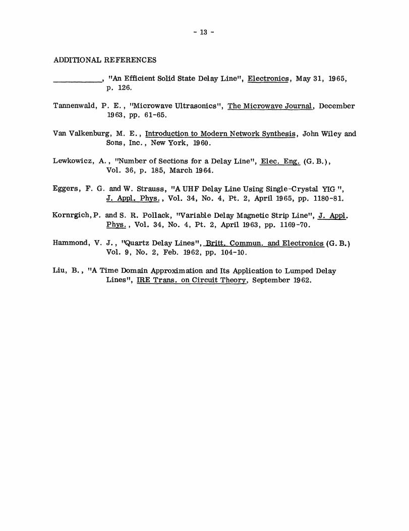
ADDITIONAL REFERENCES
"An Efficient Solid State Delay Line", Electronics, May 31, 1965,p. 126.
Tannenwald, P. E. , "Microwave Ultrasonics", The Microwave Journal, December1963, pp. 61-65.
Van Valkenburg, M. E. , Introduction to Modern Network Synthesis, John Wiley andSons, Inc. , New York, 1960.
Lewkowicz, A., "Number of Sections for a Delay Line" Elec. E g. (G.13.),Vol. 36, p. 185, March 1964.
Eggers, F. G. and W. Strauss, "A UHF Delay Line Using Single-Crystal YIG ",J, Appl. Phys. , Vol. 34, No. 4, Pt. 2, April 1965, pp. 1180-81.
Kornrgich, P. and S. R. Pollack, "Variable Delay Magnetic Strip Line", J. ApApl.Phys. , Vol. 34, No. 4, Pt. 2, April 1963, pp. 1169-70.
Hammond, V. J. , "Quartz Delay Lines", Britt. Commun. and Electronics (G. B.)Vol. 9, No. 2, Feb. 1962, pp. 104-10.
Liu, B. "A Time Domain Approximation and Its Application to Lumped DelayLines", IRE Trans. on Circuit Theory, September 1962.