natural and step responses of rlc circuit
TRANSCRIPT

11C.T. PanC.T. Pan 11
NATURAL AND NATURAL AND STEP RESPONSES STEP RESPONSES OF RLC CIRCUITSOF RLC CIRCUITS
22C.T. PanC.T. Pan
CONTENTSCONTENTS8.1 Linear Second Order Circuits8.1 Linear Second Order Circuits
8.2 Solution Steps8.2 Solution Steps
8.3 Finding Initial Values8.3 Finding Initial Values
8.4 The Natural Response of a Series/Parallel 8.4 The Natural Response of a Series/Parallel RLC Circuit RLC Circuit
8.5 The Step Response of a Series/Parallel 8.5 The Step Response of a Series/Parallel RLC CircuitRLC Circuit
8.6 State Equations8.6 State Equations22

33C.T. PanC.T. Pan 33
8.1 Linear Second Order Circuits8.1 Linear Second Order Circuits
nn Circuits containing two energy storage elements.Circuits containing two energy storage elements.nn Described by differential equations that contain Described by differential equations that contain
second order derivatives.second order derivatives.nn Need two initial conditions to get the unique Need two initial conditions to get the unique
solution.solution.
44C.T. PanC.T. Pan 44
n Examples8.1 Linear Second Order Circuits8.1 Linear Second Order Circuits
(a) RLC parallel circuit
(b) RLC series circuit
( )i t( )sv t
( )v t+
−
( )si t

55C.T. PanC.T. Pan 55
8.1 Linear Second Order Circuits8.1 Linear Second Order Circuits(c) 2L+R , RL circuit
( )sv t
1R 2R
1L 2L
(d) 2C+R , RC circuit R
C2C1( )si t
66C.T. PanC.T. Pan 66
8.2 Solution Steps8.2 Solution StepsStep1 : Choose nodal analysis or mesh Step1 : Choose nodal analysis or mesh
analysis analysis approachapproachStep2 : Differentiate the equation as many Step2 : Differentiate the equation as many
times as required to get the standard times as required to get the standard form of a second order differential form of a second order differential equation .equation .
2
2 ( )d x dxa b x y tdt dt
+ + =

77C.T. PanC.T. Pan 77
Step 3 : Solving the differential equationStep 3 : Solving the differential equation(1) homogeneous solution (1) homogeneous solution (2) particular solution(2) particular solution
8.2 Solution Steps8.2 Solution Steps
( )hx t( )px t
( ) ( ) ( )h px t x t x t= +
Step 4 : Find the initial conditionsStep 4 : Find the initial conditionsand and andand then get the then get the
unique solution unique solution (0 )x + (0 )d x
dt+
88C.T. PanC.T. Pan 88
8.3 Finding Initial Values8.3 Finding Initial ValuesUnder DC steady state, L is like a short circuit Under DC steady state, L is like a short circuit and C is like an open circuit.and C is like an open circuit.

99C.T. PanC.T. Pan 99
8.3 Finding Initial Values8.3 Finding Initial ValuesUnder transient condition, L is like an open circuit Under transient condition, L is like an open circuit and C is like a short circuit because and C is like a short circuit because iiLL(t(t) and ) and vvCC(t(t) ) are continuous functions if the input is bounded.are continuous functions if the input is bounded.
1010C.T. PanC.T. Pan 1010
8.3 Finding Initial Values8.3 Finding Initial ValuesUnder transient condition, L is like an open circuit Under transient condition, L is like an open circuit and C is like a short circuit because and C is like a short circuit because iiLL(t(t) and ) and vvCC(t(t) ) are continuous functions if the input is bounded.are continuous functions if the input is bounded.

1111C.T. PanC.T. Pan 1111
8.3 Finding Initial Values8.3 Finding Initial Values(0 )(0 ) ,
(0 ) (0 ) (0 ) (0 )
(0 ) (0 ) (0 ) (0 )
CL
L LL L
C C Cc
+ +L C
dvdiTo find and use thedt dt
following relationsdi vdL v i
dt dt Ldv dv iC i
dt dt COne can find v (0 ) and i (0 ) using either nodal or
++
+ ++ +
+ + ++
= => =
= => =
. mesh analysis
1212C.T. PanC.T. Pan 1212
8.3 Finding Initial Values8.3 Finding Initial Valuesnn Example 1Example 1
. 0
: ( ) (0 ) , (0 )
( ) (0 ) , (0 )
( ) ( ) , ( )
The circuit is under steady stateThe switch is opened at t
dFind a i idtdb v vdt
c i v
+ +
+ +
=
∞ ∞

1313C.T. PanC.T. Pan 1313
8.3 Finding Initial Values8.3 Finding Initial Valuesnn Example 1 (cont.)Example 1 (cont.)
t < 0t < 0
i(0-) = 2 A
v(0-) = 4 V
∴∴ i(0i(0++) = i(0) = i(0--) = 2 A) = 2 A
v(0v(0++) = v(0) = v(0--) = 4 V) = 4 V
1414C.T. PanC.T. Pan 1414
8.3 Finding Initial Values8.3 Finding Initial Valuesnn Example 1 (cont.)Example 1 (cont.)
t = 0t = 0++
(0 ) , (0 )
(0 ) , (0 )
LL
CC
Vdi dL V idt dt L
idv dC i vdt dt C
++
++
= ∴ =
= ∴ =
Q
Q

1515C.T. PanC.T. Pan 1515
8.3 Finding Initial Values8.3 Finding Initial Valuesnn Example 1 (cont.)Example 1 (cont.)
: 2A 4 (0 ) + 4V = 12V
(0 ) 0
(0 ) 0
: (0 ) = 2A
(0 ) 0
(0 ) 2 20 V/S0.1
L
L
C
C
KVL vvd idt
KCL id vdti
C
+
+
+
+
+
+
× +
∴ =
∴ =
∴ =
∴ = =
1616C.T. PanC.T. Pan 1616
8.3 Finding Initial Values8.3 Finding Initial Valuesnn Example 1 (cont.)Example 1 (cont.)
4Ω
2Ω
0.25H
0.1F+v-
12Vt=0
i
( ) 0 ( ) 12V
L is short circuitdC is open
iv
∴ ∞ =∞ =
t → ∞

1717C.T. PanC.T. Pan 1717
8.3 Finding Initial Values8.3 Finding Initial Valuesnn Example 2Example 2
4Ω
3u(t)A 0.6H1__2 F
+vc-
20V
+vR-
2ΩiL
L L: ( ) (0 ) , (0 ) , ( )
( ) (0 ) , (0 ) , ( )
( ) (0 ) , (0 ) , ( )
L
C C C
R R R
dFind a i i idtdb v v vdtdc v v vdt
+ +
+ +
+ +
∞
∞
∞
1818C.T. PanC.T. Pan 1818
8.3 Finding Initial Values8.3 Finding Initial Valuesnn Example 2 (cont.)Example 2 (cont.)
4Ω
3u(t)A 0.6H1__2 F
+vc-
20V
+vR-
2ΩiL
4Ω+vc-
20V
+vR-
2ΩiL
(0 ) 0
(0 ) 20
(0 ) 0
L
c
R
iv Vv
−
−
−
∴ =
= −
=
t < 0t < 0

1919C.T. PanC.T. Pan 1919
8.3 Finding Initial Values8.3 Finding Initial Valuesnn Example 2 (cont.)Example 2 (cont.)
4Ω
3u(t)A 0.6H1__2 F
+vc-
20V
+vR-
2ΩiL t = 0t = 0++
(0 ) (0 ) 0
(0 ) (0 ) 20L L
c c
i iv v V
+ −
+ −
∴ = =
= = −
2020C.T. PanC.T. Pan 2020
8.3 Finding Initial Values8.3 Finding Initial Valuesnn Example 2 (cont.)Example 2 (cont.)
4Ω
3u(t)A 0.6H1__2 F
+vc-
20V
+vR-
2ΩiL
t = 0t = 0++
3A
4Ω
2Ωic(0+)+
vR(0+)-
+ vo (0+) -
24(0 ) 3 2
2 4(0 ) 2 2 4
2(0 ) 3 12 4
(0 ) 0(0 ) 0
(0 ) 1 (0 ) 2 12
(0 ) ?
R
c
LL
cc
R
i A A
v A V
i A A
vd idt L L
id Vv Sdt cd vdt
+Ω
+
+
++
++
+
= × =+
= × =
= × =+
∴ = = =
= = =
=

2121C.T. PanC.T. Pan 2121
8.3 Finding Initial Values8.3 Finding Initial Valuesnn Example 2 (cont.)Example 2 (cont.)
4Ω
3u(t)A 0.6H1__2 F
+vc-
20V
+vR-
2ΩiL t > 0t > 0++
3A
4Ω
1__2 F
+vc-
20V
2Ω
iL+vR- 0.6H
+ vo -
: 20 0
( ) ( ) ( )
(0 ) (0 ) (0 ) ( )
R o c
R o c
R o c
From KVL v v vTake derivative
d d dv t v t v tdt dt dtd d dv v v Adt dt dt
+ + +
− + + + =
= +
∴ = + LL
2222C.T. PanC.T. Pan 2222
8.3 Finding Initial Values8.3 Finding Initial Valuesnn Example 2 (cont.)Example 2 (cont.)
4Ω
3u(t)A 0.6H1__2 F
+vc-
20V
+vR-
2ΩiL t > 0t > 0++
3A
4Ω
1__2 F
+vc-
20V
2Ω
iL+vR- 0.6H
+ vo -
( )( ) , : 32 4
1 1 0 ( ) ( ) ( )2 4
oR
R o
v tv tAlso from KCL ATake derivative
d dv t v t Bdt dt
= +
= + LL

2323C.T. PanC.T. Pan 2323
8.3 Finding Initial Values8.3 Finding Initial Valuesnn Example 2 (cont.)Example 2 (cont.)
( ) (0 ) 2 (0 ) ( )
( ) ( )
(0 ) 2 (0 ) 2
2 V (0 ) S3
o R
R R
R
d dFrom B v v Cdt dt
From A and Cd dv vdt dtd vdt
+ +
+ +
+
= −
= − +
∴ =
LL
2424C.T. PanC.T. Pan 2424
8.3 Finding Initial Values8.3 Finding Initial Valuesnn Example 2 (cont.)Example 2 (cont.)
4Ω
3u(t)A 0.6H1__2 F
+vc-
20V
+vR-
2ΩiL t t →∞→∞
3A
4Ω
20V
2Ω
iL+
vR( )-
+vc( )
-
2( ) 3 12 4
( ) 20 ( ) 3 (2 4 ) 4
L
c
R
i A A
v Vv A V
∴ ∞ = × =+
∞ = −∞ = × Ω Ω =P
2525C.T. PanC.T. Pan 2525
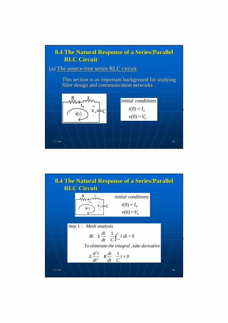
(a) (a) The sourceThe source--free series RLC circuitfree series RLC circuit
This section is an important background for studying This section is an important background for studying filter design and communication networks . filter design and communication networks .
0
0
(0)
(0)
initial conditionsi Iv V
= =
8.4 The Natural Response of a Series/Parallel 8.4 The Natural Response of a Series/Parallel RLC CircuitRLC Circuit
2626C.T. PanC.T. Pan 2626
0
0
(0)
(0)
initial conditionsi Iv V
= =
2
2
1 : 1 0
1 0
t
Step Mesh analysisdiRi L i dtdt C
To eliminate the integral , take derivatived i diL R idt dt C
−∞+ + =
+ + =
∫
8.4 The Natural Response of a Series/Parallel 8.4 The Natural Response of a Series/Parallel RLC CircuitRLC Circuit

2727C.T. PanC.T. Pan 2727
0
0
(0)
(0)
initial conditionsi Iv V
= =
:
:
2
2 2 20 0
0
Step 2 Homogeneous solution , characteristic equationR 1S + S + = 0L LC
R 1S +2αS +ω = 0 α , ω2L LC
ω undamped resonant frequency (rad/s)
⇒ @ @
: α damping factor or neper frequency
8.4 The Natural Response of a Series/Parallel 8.4 The Natural Response of a Series/Parallel RLC CircuitRLC Circuit
2828C.T. PanC.T. Pan 2828
0
0
(0)
(0)
initial conditionsi Iv V
= =
( ) 1 21 2
(0 ) (0 ) .
2 21 0
2 22 0
S t S t
characteristic roots (natural frequencies)S = -α+ α -ω
S = -α - α -ωi t A e A e
dNeed two initial conditions , i.e. , i and idi
+ +
∴ = +
8.4 The Natural Response of a Series/Parallel 8.4 The Natural Response of a Series/Parallel RLC CircuitRLC Circuit

2929C.T. PanC.T. Pan 2929
( ) 1 2
0
1 2
0
1 2
( )
( = )
2
S t S t
Case 1 Overdamped Case > Two real roots
i t A e A eCase 2 Critically Damping Case Equal real roots
RS SL
α ω
α ω
α
= +
= = − = −
( ) ( )2 1 ti t A At e α−= +
8.4 The Natural Response of a Series/Parallel 8.4 The Natural Response of a Series/Parallel RLC CircuitRLC Circuit
3030C.T. PanC.T. Pan 3030
( )
0
1
2
2 20
1 2
( )
cos si
d
d
d
td
Case 3 Underdamped Case < Complex conjugate roots
S jS j
damping frequency
i t e B t Bα
α ω
α ωα ω
ω ω α
ω−
= − += − −
−
= +
@
( )n dtOnce i(t) is obtained ,solutions of other variables can be obtained from this mesh current.
ω
8.4 The Natural Response of a Series/Parallel 8.4 The Natural Response of a Series/Parallel RLC CircuitRLC Circuit

3131C.T. PanC.T. Pan 3131
nn The damping effect is due to the presence of resistance R .The damping effect is due to the presence of resistance R .
nn The damping factor The damping factor αα determines the rate at which the determines the rate at which the response is damped .response is damped .
nn If R=0 , the circuit is said to be lossless and the If R=0 , the circuit is said to be lossless and the oscillatory response will continue .oscillatory response will continue .
nn The damped oscillation exhibited by the The damped oscillation exhibited by the underdampedunderdampedresponse is known as ringing . It stems from the ability of response is known as ringing . It stems from the ability of the L and C to transfer energy back and forth between the L and C to transfer energy back and forth between them .them .
8.4 The Natural Response of a Series/Parallel 8.4 The Natural Response of a Series/Parallel RLC CircuitRLC Circuit
3232C.T. PanC.T. Pan 3232
0
0
0
3 : 0 , (0 ) (0 )
01 (0 ) (0 ) 0
(0 ) (0 )
Step Initial Conditiont i i I
From mesh equation , let tdRi L i idtdt C
Vd R Ri idt L L L
+
+ + −
+
+ +
−∞
+ +
= = =
=
+ + =
∴ = − − = −
∫0
0VIL
−
8.4 The Natural Response of a Series/Parallel 8.4 The Natural Response of a Series/Parallel RLC CircuitRLC Circuit

3333C.T. PanC.T. Pan 3333
0 0
0 0
0
(0 ) ( )
(0 )
L
or from equivalent circuit at tdL i v I R Vdt
I R Vd idt L L
+
+
+
=
= = − +
∴ = − −
vL V0
i
R
I0
8.4 The Natural Response of a Series/Parallel 8.4 The Natural Response of a Series/Parallel RLC CircuitRLC Circuit
3434C.T. PanC.T. Pan 3434
(b) (b) The sourceThe source--free parallel RLC circuitfree parallel RLC circuit
initial inductor current Io
initial capacitor voltage Vo
2
2
:1 0
1 1 0
t
Step 1 Nodal Equationv dvvdt CR L dt
Taking derivative to eliminate the integral d v dv vdt RC dt LC
+ + =
+ + =
∫
8.4 The Natural Response of a Series/Parallel 8.4 The Natural Response of a Series/Parallel RLC CircuitRLC Circuit

3535C.T. PanC.T. Pan 3535
2
2 2 20 0
:
1 1 01 1 2 0 ,
2 (
Step 2 Homogeneous solution Characteristic equation
S SRC LC
S SRC LC
characteristic roots natura
α ω α ω
+ + =
+ + = ⇒ @ @
2 21 0
2 22 0
)
l frequenciesS
S
α α ω
α α ω
= − + −
= − − −
8.4 The Natural Response of a Series/Parallel 8.4 The Natural Response of a Series/Parallel RLC CircuitRLC Circuit
3636C.T. PanC.T. Pan 3636
8.4 The Natural Response of a Series/Parallel 8.4 The Natural Response of a Series/Parallel RLC CircuitRLC Circuit
CASE 1. CASE 1. OverdampedOverdamped Case (Case (αα>w>w0 0 ))
CASE 2. Critically Damped Case (CASE 2. Critically Damped Case (αα=w=w0 0 ))
CASE 3. CASE 3. UnderdampedUnderdamped Case (Case (αα<w<w0 0 ))
( ) 1 21 2
S t S tv t A e A e= +
( ) ( )1 2tv t A A t e α−= +
( ) ( )1 2cos sintd dv t e A w t A w tα−= +

3737C.T. PanC.T. Pan 3737
( ) ( )
( ) ( )
0
0
0
3 : (0 ) (0 )
0 1 0 0
0 1 0
Step Initial Conditionv i V
From nodal equation
v dvdt C vR L dt
vdC v vdtdt R L
+
+
+ −
++
−∞
++
−∞
= =
+ + =
∴ = − −
∫
∫
( )
00
0 0
0
V IR
V Id vdt RC C
+
= − −
∴ = − −
8.4 The Natural Response of a Series/Parallel 8.4 The Natural Response of a Series/Parallel RLC CircuitRLC Circuit
3838C.T. PanC.T. Pan 3838
( )
00
0
(0 ) 0
(0 ) (0 )
, (0 )
C
C
C
or from equivalent circuit at tdC v idt
id vdt C
VFrom KCL i IR
+
+ +
++
+
=
=
∴ =
= − −
Once the nodal voltage is obtained, any other unknown Once the nodal voltage is obtained, any other unknown of the circuit can be found .of the circuit can be found .
8.4 The Natural Response of a Series/Parallel 8.4 The Natural Response of a Series/Parallel RLC CircuitRLC Circuit

1 , 0sdiL Ri idt V tdt C
+ + = >∫
2
2 0d i di iL Rdt dt C
+ + =
( ) 0 00 sV I R Vd idt L
+ − −=
Step 1. Mesh analysis (i=iL )
Case(i) take derivative
Same as natural response but with i(0+)=I0
3939C.T. PanC.T. Pan
(a) Step response of a series
RLC circuit
8.5 The Step Response of a Series/Parallel RLC 8.5 The Step Response of a Series/Parallel RLC CircuitCircuit
Case(ii) use v as unknowndvi Cdt
=
2
2sVd v R dv v
dt L dt LC LC+ + =
Step 2. Complete solution = vh+vp
( )
( ) ( )( )
1 21 2
1 2
1 2
cos sin
p s
S t S t
th
td d
v t V
A e A e overdampedv t A A t e critically damped
e A w t A w t underdamped
α
α
−
−
=
+
= + +
C.T. PanC.T. Pan 4040
8.5 The Step Response of a Series/Parallel RLC 8.5 The Step Response of a Series/Parallel RLC CircuitCircuit

Step 3. Initial conditions
( ) ( )( )
00 0
0 ?
C
v v V
d vdt
dvC idt
+ −
+
= =
=
=
( ) ( ) 00
0 Ci Id vdt C C
++∴ = =
C.T. PanC.T. Pan 4141
Then the unique solution can be determined
8.5 The Step Response of a Series/Parallel RLC 8.5 The Step Response of a Series/Parallel RLC CircuitCircuit
1 , 0t
sv dvvdt C I tR L dt
+ + = >∫
I0 , V0 Given
Step 1. Nodal equation
Case (i) Take derivative2
2
1 1 0d v dvC vdt R dt L
+ + =
Same as natural response C.T. PanC.T. Pan 4242
(b) Step response of a parallel RLC circuit
8.5 The Step Response of a Series/Parallel RLC 8.5 The Step Response of a Series/Parallel RLC CircuitCircuit

Case (ii) Let
Step 2. Complete solution = ih(t)+ip(t)
2
2
1 1 , 0sIdi d i div L i tdt dt RC dt LC LC
= ⇒ + + = >
( )
( ) ( )( )
1 21 2
1 2
1 2
cos sin
p s
S t S t
th
td d
i t I
A e A e overdampedi t A A t e critically damped
e A w t A w t undererdamped
α
α
−
−
=
+
= + +
Step 3. Initial Condition( ) ( )
( )0
0
0 0
(0 )0 LL
i i I
Vvdi dL v idt dt L L
+ −
++
= =
= ⇒ = =C.T. PanC.T. Pan 4343
8.5 The Step Response of a Series/Parallel RLC 8.5 The Step Response of a Series/Parallel RLC CircuitCircuit
nn ExampleExample
1 F2
- -0 , (0 ) = 0 , (0 ) = 12Vt i v<
1 F2
t > 0
4444C.T. PanC.T. Pan
8.5 The Step Response of a Series/Parallel RLC 8.5 The Step Response of a Series/Parallel RLC CircuitCircuit
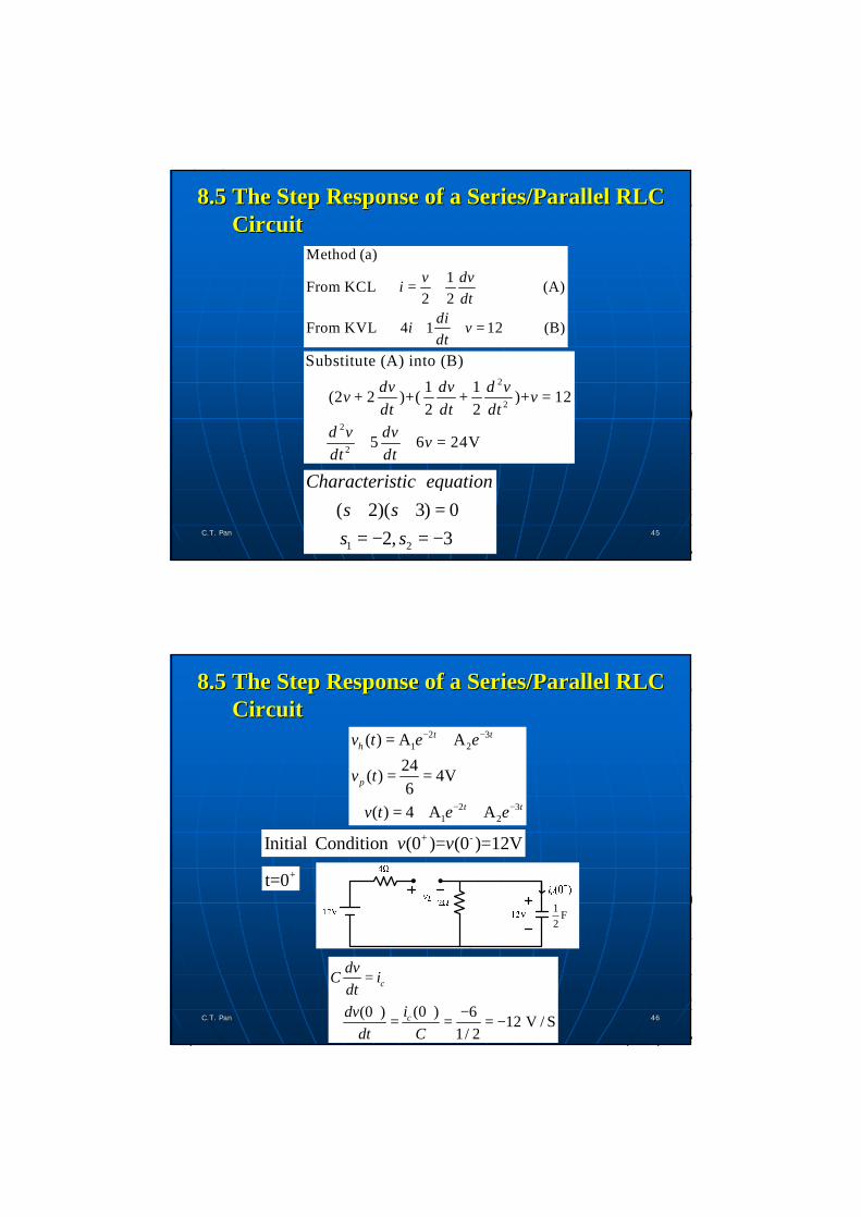
Method (a)1From KCL (A)
2 2
From KVL 4 1 12 (B)
v dvidt
dii vdt
⇒ = +
⇒ + + =
2
2
2
2
Substitute (A) into (B)1 1 (2 2 )+( + )+ 122 2
5 6 24V
dv dv d vv + v =dt dt dt
d v dv vdt dt
⇒ + + =
1 2
( 2)( 3) 0 2, 3
Characteristic equations ss s
+ + == − = − 4545C.T. PanC.T. Pan
8.5 The Step Response of a Series/Parallel RLC 8.5 The Step Response of a Series/Parallel RLC CircuitCircuit
2 31 2
2 31 2
( ) A A24( ) 4V6
( ) 4 A A
t th
p
t t
v t e e
v t
v t e e
− −
− −
= +
= =
∴ = + ++ -Initial Condition (0 )= (0 )=12Vv v
1 F2
+t=0
(0 )(0 ) 6 12 V / S1/ 2
c
c
dvC idt
idvdt C
++
=
−∴ = = = − 4646C.T. PanC.T. Pan
8.5 The Step Response of a Series/Parallel RLC 8.5 The Step Response of a Series/Parallel RLC CircuitCircuit

1 2
1 2
1 22 3
4 A A 122A 3A 12
A 12, A 4
( ) 4 12 4 , 0t tv t e e t− −
∴ + + =− − = −
∴ = = −
∴ = + − ≥
Method (b) Using Mesh Analysis
t>0i
v
4Ω
12V
1H
2Ω 1 F2
i1 i2
4747C.T. PanC.T. Pan
8.5 The Step Response of a Series/Parallel RLC 8.5 The Step Response of a Series/Parallel RLC CircuitCircuit
1 2
2 1 2
2 12
1 2
1 22
1 4 ( )2 12 ......(A)
1( ) 2 0 ......(B)1/ 2
From (B) , 2 2 2 0
6 2 12
2 2 2 0
t
di i i idt
i i i dt
di di idt dt
di i idt
di di idt dt
+ + − =
− × Ω + =
− + =
+ − =
− + + =
∫
4848C.T. PanC.T. Pan
8.5 The Step Response of a Series/Parallel RLC 8.5 The Step Response of a Series/Parallel RLC CircuitCircuit
1 F2

dIn matrix form with operator Ddt
@
1
2
6 2 12 (C)
2 2 2 0iDiD D
+ − = − +
1
2
1
2
Initial Condition , (0 ) (0 ) (0 ) 0A
(0 ) (0 ) 6A
(0 ) (0 ) 0
(0 ) 0 /
c
L
i i i i i
di vdt L
di A Sdt
+ + −
+ +
+ +
+
= = =
= = −
= =
=4949C.T. PanC.T. Pan
8.5 The Step Response of a Series/Parallel RLC 8.5 The Step Response of a Series/Parallel RLC CircuitCircuit
21 1
12
2 31
22 2
22
2 32
Eliminate variable from (C)
5 6 12
( ) 2 6 4 , 0Or eliminate variable from (C)
5 6 0
( ) 12 6 , 0
2
t t
1
t t
id i di idt dt
i t e e ti
d i di idt dt
i t e e t
− −
− −
+ + =
∴ = − + ≥
+ + =
∴ = − + ≥
5050C.T. PanC.T. Pan
8.5 The Step Response of a Series/Parallel RLC 8.5 The Step Response of a Series/Parallel RLC CircuitCircuit

Problem : (a) Time consuming to eliminate the other variable to get a higher order differential equation.
(b) It is also necessary to obtain the desired initial conditions.
(c) As the order gets higher when the network contains more energy storageelements, the process gets more complicated.
5151C.T. PanC.T. Pan
The difficulty can be overcome by using state equationformulation.
8.5 The Step Response of a Series/Parallel RLC 8.5 The Step Response of a Series/Parallel RLC CircuitCircuit
When the differential equations of a circuit is written in the following form:
1 2
1 2
1 2
( , , )
[ .... ] state vector
[ .... ] input vector
[ .. ] vector function
Tn
Tm
Tn
d x f x u tdtx x x x
u u u uf f f f
=
=
=
=
5252C.T. PanC.T. Pan
8.6 State Equation8.6 State Equation

It is said that the circuit equations are in the state
equation form.
(a) This form lends itself most easily to analog or digital
computer programming.
(b) The extension to nonlinear and/or time varying
networks is quite easy.
(c) In this form, a number of theoretic concepts of
systems are readily applicable to networks.C.T. PanC.T. Pan 5353
8.6 State Equation8.6 State Equation
For a linear time-invarying circuit , a simpler form
A B , state equation
y C D , output equation
A : n n matrix.B : n m matrix.C : n matrix.D : m matrix.
d x x udt
x u
ll
= +
= +
××××
Note that on the right hand side of the state or output
equation, only x and u are allowed. 5454C.T. PanC.T. Pan
8.6 State Equation8.6 State Equation

Step1. Pick a tree which contains all the capacitors and none of inductors.
Step2. Use the tree-branch capacitor voltages and the link inductor currents as unknown (i.e. , state) variables.Note: (a) Nodal Analysis
Every unknown of the circuit can be calculated from nodal voltages.
(b) Mesh AnalysisEvery unknown of the circuit can be calculated from mesh currents.
5555C.T. PanC.T. Pan
8.6 State Equation8.6 State Equation
(c) State Equation
l The chosen variables include both voltage and current unknown. It belongs to mixed type.
l Every unknown of the circuit can be calculated from the state variables by replacing each inductor with a current source and each capacitor with a voltage source and then solving the resulting resistive circuit.
5656C.T. PanC.T. Pan
8.6 State Equation8.6 State Equation

Step3. Write a fundamental cutset equation (i.e. KCL equation) for each capacitor.Note that in these cutset equations, all branch currents must be expressed in terms of x and u.
Step4. Write a fundamental loop equation (i.e. KVL equation) for each inductor.Note that in these loop equations, all branch voltages must be expressed in terms of x and u.
Step5. Rearrange the above equations into standard form and find the solution for the given initial condition.
5757C.T. PanC.T. Pan
8.6 State Equation8.6 State Equation
nExample 1
Step1 tree
5858C.T. PanC.T. Pan
8.6 State Equation8.6 State Equation

Step2 choose i and v as state variables.Step3 fundamental cutset about the capacitor tree branch.
dC = - dt 2v vi
Step4 fundamental loop for the inductor link.
dL + -12V +4 = 0dt
i v i5959C.T. PanC.T. Pan
8.6 State Equation8.6 State Equation
Step5
The desired solutions are v and i
with initial condition
1 -1 0d C 2C = + (12V)1-4 -1dt
LL L
v vi i
1 0 0y = = + (12V)
0 1 0v vi i
+
+
(0 ) = 12V
(0 ) = 0A
viC.T. PanC.T. Pan 6060
[ ]A [ ]B
[ ]C [ ]D
8.6 State Equation8.6 State Equation

nExample 23 2
3 2
12
1
22 3
2 33
3 3 3
2
2
d d d+ 5 + 4 + 3 = u(t)dtdt dt
dx = xx = (t) dtdxd (t)Let x = = x
dt dtdxd (t) dx = =dtdt dt
d d = - 5 - 4 - 3 + udtdt
v v v v
vv
v v
v v v
⇒
3 2 1
(t)
= - 5x - 4x - 3x + u(t) 6161C.T. PanC.T. Pan
8.6 State Equation8.6 State Equation
State space representation
[ ] [ ]
1 1
2 2
3 3
1
2
3
x 0 1 0 x 0d x = 0 0 1 x + 0 u(t)dt
x -3 -4 -5 x 1
x y = 1 0 0 x + 0 u(t)
x
∴
A high order differential equation can be represented in the form of state equation.
6262C.T. PanC.T. Pan
8.6 State Equation8.6 State Equation

n Example 3 : Find vR4
es
R3
i3
R1 R2 R4
L1 L2
R5
C1
C2
iL1 iL2
i4
-vC1
+
-vC2
+
a
b
c
d
e
f
hg
There are 8 nodes.
C.T. PanC.T. Pan 6363
8.6 State Equation8.6 State Equation
Step1 Pick a tree as follows :
iL1 iL2
a
b
c d
e
f
g h
+-vC1 +
-vC2
There are 7 tree branches and 3 links.
6464C.T. PanC.T. Pan
8.6 State Equation8.6 State Equation

Step2 Choose iL1, iL2 , vC1 , vC2 as unknowns.Step3 Fundamental cutsets (KCL) for capacitors.
C11 L1
C22 L1 L2
dC = dt
dC = dt
v i
v i +i
Step4 Fundamental loops (KVL) for inductors.L1
1 R1 C1 C2 R5 R4
1 L1 C1 C2 5 L1 L2 R4
dL = - - - - + dt
= -R - - - R ( )
i v v v v v
i v v i i v+ +
Note that vR4 should be expressed in terms of x and u6565C.T. PanC.T. Pan
8.6 State Equation8.6 State Equation
Absorb voltages vC2and vR5 in (iL1+ iL2) current source.
Absorb voltages vR1and vC1 in current source iL1 , and vR2 in iL2.
6666C.T. PanC.T. Pan
8.6 State Equation8.6 State Equation

3 44R4 s L1 L2
3 4 3 4
R RR= e - ( + )R +R R +R
v i i∴
C.T. PanC.T. Pan6767
8.6 State Equation8.6 State Equation
Step5
1
C1 C1
2 2C2 C2 4s
1L1 L11 2 3 4
1 1 1 1L2 L2
22
2 2 2
10 0 0C 01 1 00 0
C C 1 Rd = + eL(R R )1 1 Rdt R +R
L L L L 1L(R R)1 R0
L L L
v vv vi ii i
− +− − − − +− −
C1
C23 4 3 4 4R4 s
L13 4 3 4 3 4
L2
-R R -R R R = 0 0 + eR R R R R R
vv
vii
+ + +
3 45
3 4
R Rwhere R R + R +R
@C.T. PanC.T. Pan6868
8.6 State Equation8.6 State Equation

Special case
i1 i3
i2
From KCL i1+i2+i3 = 0
∴ i3 = -i1-i2
(a)
Inductor current i3 is dependent on i1 and i2 and is no longer a state variable.
One can choose only n-1 (here 2) inductor currents as state variables.
C.T. PanC.T. Pan6969
8.6 State Equation8.6 State Equation
(b)
From KVL vC1+vC2 = vC3
One can choose n-1 (here 2) capacitor voltages as state variables.
C.T. PanC.T. Pan7070
8.6 State Equation8.6 State Equation

n Objective 1 : Be able to find the initial values and the initial derivative values.
n Objective 2 : Be able to determine the natural response and the step response of a series RLC circuit.
n Objective 3 : Be able to determine the natural response and the step response of a parallel RLC circuit.
n Objective 4 : Be able to obtain the state equation and output equation of a linear circuit.
C.T. PanC.T. Pan 7171
SummarySummary
C.T. PanC.T. Pan 7272
SummarySummary
Chapter Problems : 8.168.258.328.408.44
Due within one week.