network coding testbed using software defined...
TRANSCRIPT

1
Network Coding Testbed Using Software Defined Radios
Final Report
SD May10-08
Alex Lee, Ben Green, Jeremy Bergan
Advisor: Aditya Ramamoorthy
Submitted: April 28, 2010
DISCLAIMER: This document was developed as part of the requirements of an electrical and computer engineering course at Iowa State University, Ames, Iowa. The document does not constitute a professional engineering design or a professional land surveying document. Although the information is intended to be accurate, the associated students, faculty, and Iowa State University make no claims, promises, or guarantees about the accuracy, completeness, quality, or adequacy of the information. Document users shall ensure that any such use does not violate any laws with regard to professional licensing and certification requirements. Such use includes any work resulting from this student-prepared document that is required to be under the responsible charge of a licensed engineer or surveyor. This document is copyrighted by the students who produced the document and the associated
2
Table of Contents
Table of Contents ................................................................................................. 2 List of Figures ...................................................................................................... 3 List of Tables........................................................................................................ 3 List of Definitions .................................................................................................. 4 Executive Summary .............................................................................................. 5 Acknowledgments ................................................................................................. 5 Problem Statement ............................................................................................... 5
General Problem Statement ................................................................................ 5 General Solution Approach .................................................................................. 5
Operating Environment ......................................................................................... 6 Intended User and Intended Uses ........................................................................... 6
Intended User ................................................................................................... 6 Intended Uses ................................................................................................... 6
Initial Assumptions and Limitations ......................................................................... 6 Initial Assumptions ............................................................................................ 6 Initial Limitations ............................................................................................... 6
Expected End Product and Other Deliverables .......................................................... 7 Market/Literature Survey ....................................................................................... 8
End Product Design ................................................................................................. 8 The Approach Used ............................................................................................... 8
Design Objectives .............................................................................................. 8 Functional Requirements ..................................................................................... 8 Non-functional Requirements .............................................................................. 9 Design Constraints ............................................................................................. 9 Technology Considerations ................................................................................ 10 Testing Requirements Considerations ................................................................. 10 Security Considerations .................................................................................... 10 Intellectual Property Considerations ................................................................... 10 Testing Approach Considerations ....................................................................... 10 Commercialization Considerations ...................................................................... 12 Possible Risks and Risk Management .................................................................. 12 Proposed Project Milestones and Evaluation Criteria ............................................. 12 Recommendations Regarding Project Continuation or Modification.......................... 13
A Detailed Design ............................................................................................... 13 System Design ................................................................................................ 14 Basic Network Design ....................................................................................... 16 ANC Network Design ........................................................................................ 16
Resources and Schedules .......................................................................................... 18 Resource Requirements ....................................................................................... 18
Personnel Effort Requirements ........................................................................... 18 Other Resource Requirements ........................................................................... 19 Financial Requirements ..................................................................................... 20
Schedules .......................................................................................................... 20 Project Schedule .............................................................................................. 20 Deliverable Schedule ........................................................................................ 22
Implementation ....................................................................................................... 23 Matlab Simulation .................................................................................................. 23
ANC System ....................................................................................................... 23 Transmission ................................................................................................... 24 Reception ....................................................................................................... 24
Testing & Simulation Results ................................................................................ 25

Troubleshooting .................................................................................................. 26 GNU Radio Implementation ..................................................................................... 27
Sync Block ......................................................................................................... 29 Decoding Block ................................................................................................... 29 Energy Detector ................................................................................................. 30 MSK .................................................................................................................. 30 Testing .............................................................................................................. 30 Issues ............................................................................................................... 31
Evaluation ............................................................................................................ 31 Lessons Learned ................................................................................................. 32 Closing Summary ............................................................................................... 33 Project Team Information .................................................................................... 34
Client/faculty advisor ....................................................................................... 34 Student Team Information ................................................................................ 34
References ......................................................................................................... 35 Appendix A .............................................................................................................. 37
Compiling GNU Radio Testbed Files .......................................................................... 37 Basic Directory Structure ..................................................................................... 37
configure.ac .......................................................................................................... 38 Makefile.am .......................................................................................................... 39 .i files .................................................................................................................. 41
run_tests ........................................................................................................... 43 How to compile once setup .................................................................................. 43
List of Figures
Figure 1 .................................................................................................................. 11 Figure 2 .................................................................................................................. 14 Figure 3: Alice-Bob topology ...................................................................................... 17 Figure 4: Chain topology ........................................................................................... 17 Figure 5: X topology ................................................................................................. 17 Figure 6 .................................................................................................................. 21 Figure 7 .................................................................................................................. 21 Figure 8 .................................................................................................................. 22 Figure 9 .................................................................................................................. 22 Figure 10 ................................................................................................................ 23 Figure 11 ................................................................................................................ 26 Figure 12 ................................................................................................................ 25 Figure 13 ................................................................................................................ 25 Figure 14: Implementation Flow ................................................................................. 28
List of Tables
Table 1 ................................................................................................................... 15 Table 2 ................................................................................................................... 18 Table 3 ................................................................................................................... 18 Table 4 ................................................................................................................... 19 Table 5 ................................................................................................................... 19 Table 6 ................................................................................................................... 20 Table 7: Directory Structure ...................................................................................... 37
4
List of Definitions
Network Coding: A theory that allows the node to combine received packets and creates the packets to send to one or more nodes. [1]
Analog Network Coding (ANC): A theory that routers forward the interfering signals instead of forwarding packets and leverage network-level information to cancel the interference and recover the signal destined to it. [4] Universal Software Radio Peripheral (USRP): A hardware device which is a high-speed USB-based board to facilitate the building of software radios. [6] Minimum-Shift Keying(MSK): A form of phase shift keying that creates the signals based on binary data consisting of sharp transitions. [7] GNU Radio: A free software development toolkit that provides the signal processing runtime and processing blocks to implement software radios using readily-available, low-cost external RF hardware and commodity processors. [8] Media Access Control (MAC): A sublayer of the Data Link Layer specified in the seven-layer OSI model (layer 2). It provides addressing and channel access control mechanisms that make it possible for several terminals or network nodes to communicate within a multipoint network, typically a local area network (LAN) or metropolitan area network (MAN). The hardware that implements the MAC is referred to as a Medium Access Controller. [14] Bit Error Ratio (BER): A measure of signal quality, and is a function of a quantity called Eb/N0, the energy per bit to noise power spectral density ratio of the signal for QPSK signal. [15]
5
Executive Summary
Current protocols for handling data on networks do not make full use of the type of information or the topology of the network. A field of study known as network coding seeks to find ways of combining and routing packets or information in order to increase the throughput and reliability of networks. This project aims to build on previous research as well as to implement a testbed and framework that can be used for future research in network coding at Iowa State. During the first semester we developed a system for setting up wireless networks and testing their properties. A base network complete with modulation, demodulation, media access control, and testing utilities was designed. The network coding technique "Analog Network Coding" as described in the paper by Katti et al. [1] was simulated in Matlab to be used at the physical layer of our testbed. We also attempted to implement this system in GNU Radio so we could use the testbed over the air. Though we did not get this fully tested, we do have C++ source code for the project and documentation so a group in the future can finish the project.
Acknowledgments
Aditya Ramamoorthy's Ph.D student, Shizheng Li, will be assisting us in the lab, providing guidance in design decisions, and answering questions we have about Network Coding. He has already provided us access to research papers on the topics of Network Coding, Analog Network Coding, and Wireless Network Protocols. He will be an asset to our team throughout the senior design project.
Problem Statement
General Problem Statement
Current network protocols are not the most efficient which leads to the question of how one can improve them? Network Coding is a scheme that has a large throughput advantage over current wired and wireless networks. We plan to build a network coding testbed to implement network coding protocols. One that we think has potential is Analog Network Coding.
General Solution Approach
To build a testbed, we need to build physical layer and media access control layer support to enable network coding at different protocols. We shall implement basic modulation schemes and the analog network coding physical layer algorithm [1]. Specifically, in ANC, two transmitters send at the same time and the MSK modulated signals will interfere at the router. Where they will be amplified and broadcast to surrounding nodes. When the receivers receive the interfered signals they will use proper algorithms to demodulate the interfered message. This could potentially double the throughput of the router. Along with this simple approach we will also be researching new methods of ANC that could potentially be used with traditional wireless networks.
6
In order to support higher layer network coding protocols, we shall also implement a simplified 802.11 MAC protocol. This is also useful when we want to apply ANC in networks with general topology.
Operating Environment
The end-product of our project will be in the form of software which requires certain hardware like computers and USRPs. Most of hardware that runs the software is placed in the lab. Within the lab condition, all the hardware should operate. The end-product will be software which won’t be seen physically, so it won’t be damaged by the physical impact.
Intended User and Intended Uses
Intended User
The end-product is designed as the testing tool of the network coding protocols, including analog network coding. The user should understand the basic concepts of Analog Network Coding and how to operate systems like USRPs, computers, and the software. The intended user should be researchers or engineers who design new network protocols based on network coding, or people who want to set up a small scale wireless mesh network.
Intended Uses
This product is useful in prototyping new network coding protocols. It provides low layer support so that higher layer protocols can be implemented quickly. It will also be equipped with analog network coding, which is expected to increase the throughput of a small wireless network. The expected end-product is a network coding testbed and a prototype of Analog Network Coding. The end-product will be useful among the small wireless networks connecting several computers. However, the product might not be able to integrate with general wireless networks that people currently use.
Initial Assumptions and Limitations
Initial Assumptions
Since its main use will be in a lab, no assumptions are made about the environment of the end-product, except that it will be tested under reasonable conditions.
Initial Limitations
The research nature of this project leaves it very open in terms of what can and can't be done. As a result there are only the limitations of the currently owned hardware, and the time needed to implement the end product. The department currently owns seven Universal Software Radio Peripherals (USRPs) for use in our project with another seven ordered. This means there is a maximum of 14 radios, or nodes, in any network layout developed for or tested in. In the future the software should theoretically be scalable to larger networks, but this is the maximum size the team will be able to test with.
7
Each of the USRPs come with a choice of many daughter-boards, which allow access to a certain portion of the wireless spectrum. The daughter-boards that are made available can transmit and receive from 2.4 GHz to 2.5 GHz, bounding the testing to this range of frequencies. Again, what applies here should theoretically also be applicable to other bands, but can only be tested in this area of the spectrum. The computers that the USRPs are hooked up to, and on which all of the computation for this system will be done, are several year old Dell Optiplex desktops. Any software created must run on modest hardware. The main limiting factor will be the CPU of the machines, as this software will require heavy number crunching. For any logging of data, RAM and hard drive space may come in to play, but are not considered as important to the end product. Another very important consideration is the amount of time to finish the work. The project lasts two semesters, and each student has only a certain amount of time per week to devote to it. This is the main limiter of the scope and complexity of the project considering its open-ended nature. The team must make judgments on which features and what functionality are most important, and how much time to allot to individual tasks in order to ensure that a working product is finished on time.
Expected End Product and Other Deliverables
The end product of this project will be a network coding testbed. All software, including any binaries, source, and documentation will be made available to the client throughout the project, and will be judged to be finished when:
The software is compilable, installable, and compatible, with the provided hardware.
The software can be used to set up a wireless network between an arbitrary number of computers, with a range of network topologies.
The network created uses network coding techniques to show equal or better throughput than a traditional wireless network, and that this can be measured quantitatively using tools provided or developed by the team. All source code and functionality is documented thoroughly, and to the client's satisfaction. This should all be accomplished by the scheduled due date for the project in the Spring of 2010.
The product will be installed on several computers and will be used to configure and test a wireless network that implements network coding techniques to improve throughput over traditional wireless networks.
Various important documents will be developed and delivered to the client while the project is in progress, including the project plan (10/9/2009), the design document (11/16/2009), and the Design Report (12/1/2009). The project plan will detail initial goals, requirements, descriptions, and schedules so that the client may assess that the overarching goals for the project are understood by the project team. The design document and design report will detail how the problem is to be solved, including technical descriptions of all components and steps involved.

8
During the second semester we are expected to create a poster (4/14/2010) which provides an overview of the entire project including design, implementation, and testing. We are also will give an IPR presentation (4/29/2010), and have a final report that includes an updated version of our project plan and design document. All important information pertaining to the second semester, including implementation and testing, must also be included in the final report.
Market/Literature Survey
Since this is a research project we didn’t really look at much market information, though we knew there was a need/desire for this technology in the marketplace. Anytime you can increase throughput of a network there will be people interested. We did do an extensive literature survey though, which consisted of us reading many research papers on the topic of network coding. In the end we decided that Embracing wireless interference: Analog Network Coding was most interesting to us. Our design process focused around this implementation of network coding. We plan to implement ANC in our testbed.
End Product Design
The Approach Used
Design Objectives
Build a network coding testbed to implement network coding protocols.
Build physical layer and MAC layer support to enable network coding of different protocols.
Implement basic modulation schemes and the analog network coding physical layer algorithm.
Implement a simplified 802.11 MAC protocol.
Our objective is to develop a testbed that consists of a set of tools that will facilitate practical research on network coding. The testbed should allow the users to be able to switch between different modulation schemes, network designs and topologies.
The testbed should implement a variety of modulation schemes that can be used to send messages.
A physical layer, network layer, host layer, and MAC layer will be used to give the wireless network its functionality.
Functional Requirements
FR01: The software shall implement the system detailed in the paper Embracing Wireless Interference: Analog Network Coding [1].
FR02: The system shall be used as the practical application to arbitrary network topologies.
9
FR03: We shall integrate our ANC implementation with a simple traditional wireless network.
FR04: The system shall show equal or better throughput than a traditional wireless network.
FR05: The system shall include software to measure packet loss, latency, and throughput.
FR06: The system shall have a layer devoted to collecting and logging data that can be used for testing and verification purposes.
FR07: QPSK, MSK, QAM modulation schemes must be implemented.
FR08: Simplified 802.11 MAC that allow proper distributed scheduling between the computers.
FR09: The Usage of USRP and GNU radio signal processing libraries shall need for the system.
FR10: Each functional block of the system shall be simulated in Matlab before implemented in GNU Radio.
FR11: The Matlab simulation results must be compared and verified with the GNU Radio implementation.
FR12: The testbed shall be extensible, allowing further develop and research of networking.
Non-functional Requirements
NF01: We shall completely document all procedures to ensure that the test bed is usable by researchers in the future.
NF02: Our code shall be added to the GNU Radio source code.
Design Constraints
USRP o Number o Bandwidth o Frequency range o Transmission power
Computing
o Processing Speed o Number of Computer
Time o Pursue limited set of network coding techniques or features

10
The network coding testbed requires a USRP to be connected to a computer, therefore the number of nodes in the network is constrained by the number of USRPs and computers available to our group. Though this is an important consideration, most of the network topologies we plan implement can be tested with 5 or fewer nodes. In our network each node can act as a transmitter, receiver, or router, which gives us even greater flexibility.
Our biggest constraint may be time. The testbed should allow the user to use many different types of modulation schemes, network types, and topologies. We will only have time to implement a few of these features, but we need to make sure the testbed is extensible to allow for development in the future. If we try to implement too many different features we may not have enough time to finish the actual testbed.
Technology Considerations
The selection of an approach to network coding is central to the project.There are a few ideas that have been considered, Analog Network Coding [1], COPE [2], and Random Linear Network Coding [3]. Our system will use Analog Network coding, and if there is enough time to complete it, Random Linear Network Coding.
Testing Requirements Considerations
The team will need to develop tools to test properties of the network, and compare it to wireless networks that do not implement network coding scheme developed. The tools should at least compare throughput of the two different networks.
Security Considerations
The USRPs are stored in 3126 Coover, which is locked to ensure they are not stolen. Each group member was given a key to the lab and are expected to lock it when they leave.
Safety Considerations
This project has been assessed to have no significant safety issues.
Intellectual Property Considerations
The intellectual property will belong to both the student team and the client.
Testing Approach Considerations
Each stage of our design will be tested in a Matlab simulation before we implement it in GNU radio. By simulating in Matlab, we can quickly test our design in controlled environment.
11
Matlabs standard libraries already contain many functions and modulation schemes that we need for our testing.
Once we run the Matlab simulations we will verify that the results are correct. Results can be verified by comparing the simulation to known values, or through making sure the transmission matches the reception. Once we are satisfied with the result we will implement the code in GNU Radio. This involves us creating the signal processing blocks in C++ and combining the blocks with Python.
Once the blocks are implemented in GNU Radio we will test the code by broadcasting and receiving using the USRPs. If these results match what we got in the Matlab simulation we can be certain we implemented it correctly.
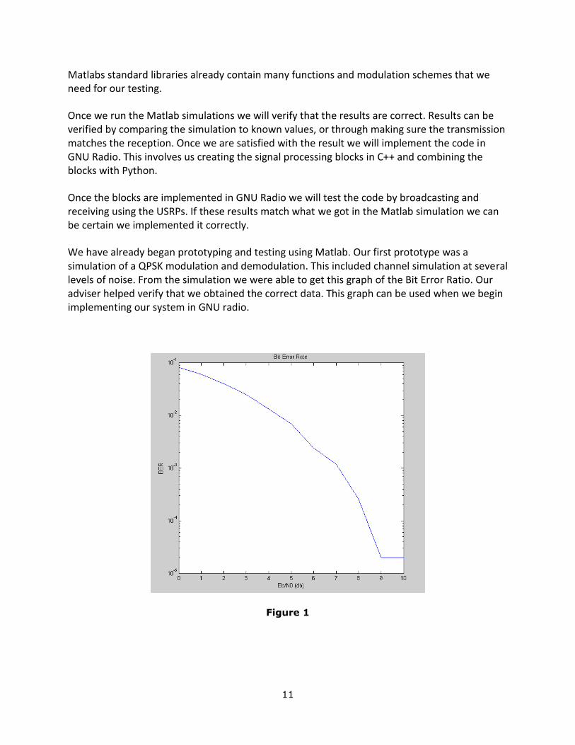
We have already began prototyping and testing using Matlab. Our first prototype was a simulation of a QPSK modulation and demodulation. This included channel simulation at several levels of noise. From the simulation we were able to get this graph of the Bit Error Ratio. Our adviser helped verify that we obtained the correct data. This graph can be used when we begin implementing our system in GNU radio.
Figure 1
12
At the start of the second semester we started a full simulation of an ANC transmission and reception using Matlab. This has helped us understand our design better, and also provide valuable data to compare with our GNU Radio implementation.
To evaluate the effectiveness of the testbed we will use the data logged by the testing layer. This will allow users to investigate the throughput, bit error rate, packet loss, and visualizations of data in each network. If we insure the testing layer works correctly, it should allow us to easily test the rest of the system.
Commercialization Considerations
The end product is only for use in an academic environment. Any research will be open to the public free of charge.
Possible Risks and Risk Management
Because our group lacks expertise in the given field we believe this could be one of the biggest risk in the project. Network Coding is a relatively new field of research, and because of this there is not a lot of places to find help when we tackle certain problems. GNU Radio does not have an implementation of Network Coding, so we will have to design and write all the code ourselves. None of our group members have had previous experience with Network Coding. As stated in our limitations, our computers could be a limiting factor in what types of signals we can process. Our adviser is currently looking into whether we can get new computers in the Network Coding lab.
Below is a list of possible risks:
Hardware Failure
USRPs
Computers
People Failure
Loss of team members
Lack of particular expertise
Management Failure
Missed deadline
Scope creep
Proposed Project Milestones and Evaluation Criteria
Implement ANC
Implement General Wireless Network
13
Integrate ANC with a general wireless network
Develop tools to test the network and compare networks with and without network coding
Recommendations Regarding Project Continuation or Modification
Physical Layer o M-QAM(M-ary Quadrature Amplitude Modulation) [12] o M-PSK(M-ary Phase Shift Keying) [11] o OFDM(Orthogonal Frequency-Division Multiplexing) [10]
Network Layer o Implement TCP/IP
Testing and Logging Layer o Inter-node coordination
Nodes coordinate over internet Run / Stop all nodes from central location Gathering statistical data from all nodes to a central location
o Single-computer simulation Simulate channel effects Simulate topology Able to test a network on a single computer
o Component Benchmarking Component processing time per input sample Help in identification of computation chokepoints
Other Network Coding Schemes o Random Linear Network Coding [9] o MIXIT [13]
A Detailed Design
1. Framework a) Physical Layer
Modulation
Demodulation
Carrier Sense b) Network Layer
Packetization of Data
Routing path is given for each packet c) Host Layer
Generates data to send
Receives and processes data
Several possible data sources/types
Streaming media (audio/video)
Randomized Data
14
Known Pattern
Kernel network interface d) Testing and Logging Framework
Select logging/testing options
Logging data to file from individual layers/components
Scopes/Visualization of data from individual layers/components
Generation of statistics o Bit Error Rate o Packet Loss o Throughput
Comparison of multiple schemes
Validation o Verify Correctness of data o Verify correctness of statistics based on simulations
2. Network Types a) Basic Network
Physical o MSK o QPSK
MAC o Simplified 802.11 MAC
b) ANC
Physical o MSK o ANC decoding
MAC o Simplified 802.11 MAC o Interference coordination
System Design
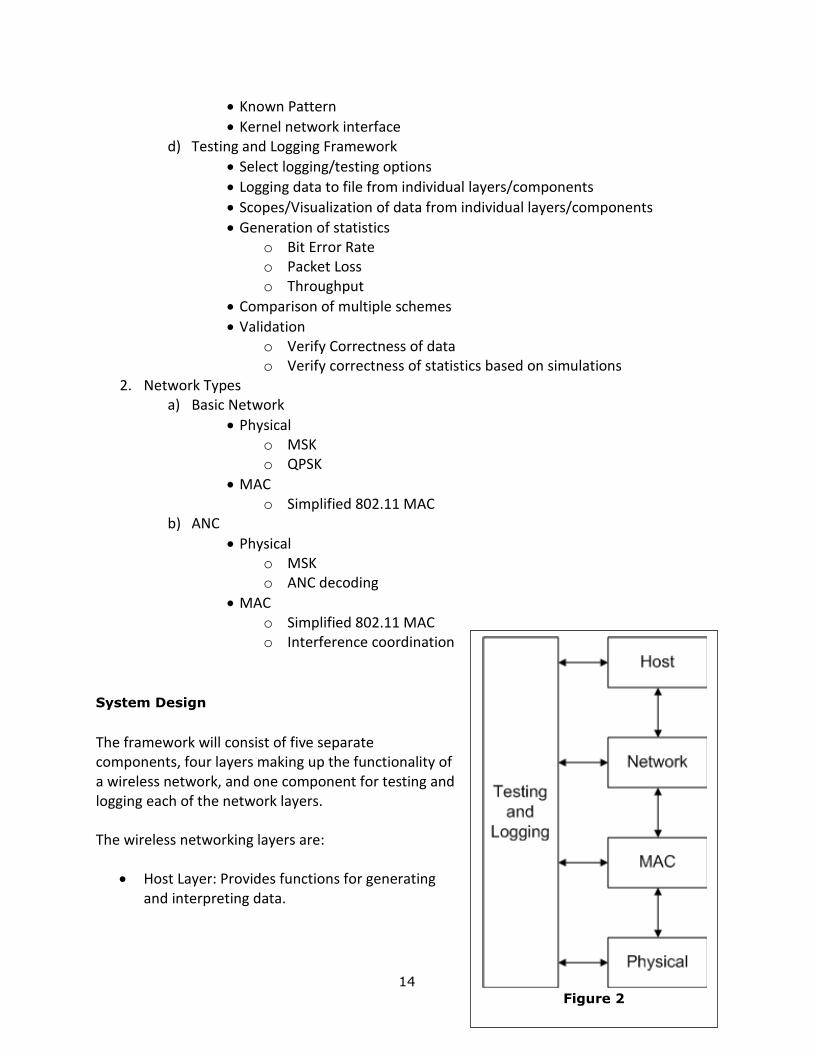
The framework will consist of five separate components, four layers making up the functionality of a wireless network, and one component for testing and logging each of the network layers. The wireless networking layers are:
Host Layer: Provides functions for generating and interpreting data.
Figure 2
15
Network Layer: Packetization of data and routing. Contains higher level functions of networking.
MAC Layer: Coordinates channel access between nodes.
Physical Layer: Does most signal processing work. Defines modulation, demodulation, carrier sensing, signal filtering. Interfaces with USRP to transmit/receive data.
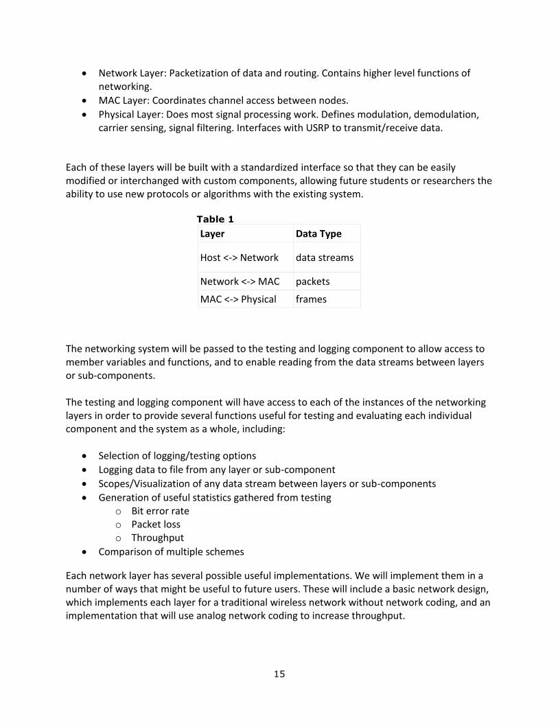
Each of these layers will be built with a standardized interface so that they can be easily modified or interchanged with custom components, allowing future students or researchers the ability to use new protocols or algorithms with the existing system.
Table 1
Layer Data Type
Host <-> Network data streams
Network <-> MAC packets
MAC <-> Physical frames
The networking system will be passed to the testing and logging component to allow access to member variables and functions, and to enable reading from the data streams between layers or sub-components. The testing and logging component will have access to each of the instances of the networking layers in order to provide several functions useful for testing and evaluating each individual component and the system as a whole, including:
Selection of logging/testing options
Logging data to file from any layer or sub-component
Scopes/Visualization of any data stream between layers or sub-components
Generation of useful statistics gathered from testing o Bit error rate o Packet loss o Throughput
Comparison of multiple schemes
Each network layer has several possible useful implementations. We will implement them in a number of ways that might be useful to future users. These will include a basic network design, which implements each layer for a traditional wireless network without network coding, and an implementation that will use analog network coding to increase throughput.
16
Basic Network Design
Physical Layer
Several commonly used modulation schemes will be implemented including Quadrature Phase Shift Keying (QPSK), Minimum Shift Keying (MSK), and Quadrature Amplitude Modulation (QAM).
To detect whether or not a signal is being transmitted we simply compare the energy of the channel to the average noise energy.
MAC Layer
The MAC will be implemented as a simplified version of the 802.11 MAC, which is to say it will use the Carrier Sense Multiple Access with Collision Avoidance (CSMA/CA) with exponentially increasing random back-off times as described in the 802.11 standard.
Network Layer
The packet layout will be very simple containing only information on source and destination nodes. Each node will contain global knowledge of the network at this level and will look up routing information for each packet in a table. Routing protocols are outside the scope of this project but would possibly make a good subject for implementation for later teams.
Host Layer
For testing purposes the host layer will be able to generate data randomly, or in several predefined patterns. We will be able to compare transmitted and received versions of this data as a method of testing.
Also implemented will be sending and receiving of audio or video streams for demonstration purposes.
ANC Network Design
Physical Layer
In addition to MSK modulation, the ANC physical layer will contain sub-components to perform detection and decoding of interfered signals as described in the ANC paper [1].
MAC Layer
The ANC MAC layer works on a modified version of the basic network MAC. In the header of a frame to be transmitted, a node will also send information about the source and destination of the next several packets in the buffer waiting to be sent. Surrounding nodes will keep a table of this information about the nodes in their area and use it to detect opportunities where ANC would be beneficial. An opportunity for coding occurs when two nodes have a message to transmit but would interfere at the destination of at least one of the messages, and the next hop for the interfered message has knowledge of the data contained in one of the transmitting nodes’ packets. Several examples are given below.
17
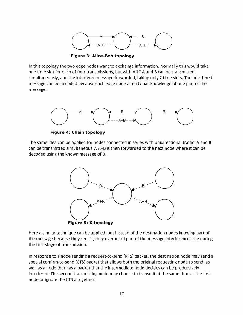
Figure 3: Alice-Bob topology
In this topology the two edge nodes want to exchange information. Normally this would take one time slot for each of four transmissions, but with ANC A and B can be transmitted simultaneously, and the interfered message forwarded, taking only 2 time slots. The interfered message can be decoded because each edge node already has knowledge of one part of the message.
Figure 4: Chain topology
The same idea can be applied for nodes connected in series with unidirectional traffic. A and B can be transmitted simultaneously. A+B is then forwarded to the next node where it can be decoded using the known message of B.
Figure 5: X topology
Here a similar technique can be applied, but instead of the destination nodes knowing part of the message because they sent it, they overheard part of the message interference-free during the first stage of transmission. In response to a node sending a request-to-send (RTS) packet, the destination node may send a special confirm-to-send (CTS) packet that allows both the original requesting node to send, as well as a node that has a packet that the intermediate node decides can be productively interfered. The second transmitting node may choose to transmit at the same time as the first node or ignore the CTS altogether.
18
The intermediate node would then determine whether the message needs to be forwarded, and if so, amplify and forward the signal. Detection and decoding of interfered signals is done at the physical layer as described in the ANC paper [1]. Outside the detection of coding opportunities the modified MAC works the same as the basic network MAC.
Resources and Schedules
Resource Requirements
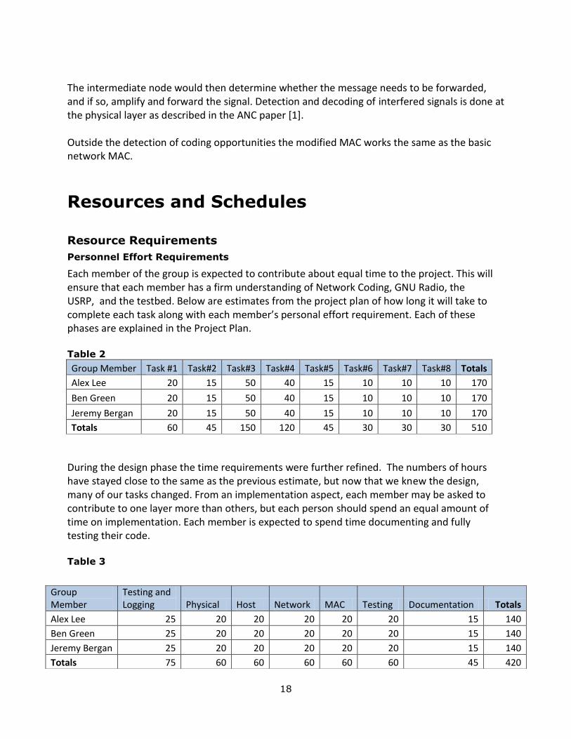
Personnel Effort Requirements
Each member of the group is expected to contribute about equal time to the project. This will ensure that each member has a firm understanding of Network Coding, GNU Radio, the USRP, and the testbed. Below are estimates from the project plan of how long it will take to complete each task along with each member’s personal effort requirement. Each of these phases are explained in the Project Plan.
Table 2
Group Member Task #1 Task#2 Task#3 Task#4 Task#5 Task#6 Task#7 Task#8 Totals
Alex Lee 20 15 50 40 15 10 10 10 170
Ben Green 20 15 50 40 15 10 10 10 170
Jeremy Bergan 20 15 50 40 15 10 10 10 170
Totals 60 45 150 120 45 30 30 30 510
During the design phase the time requirements were further refined. The numbers of hours have stayed close to the same as the previous estimate, but now that we knew the design, many of our tasks changed. From an implementation aspect, each member may be asked to contribute to one layer more than others, but each person should spend an equal amount of time on implementation. Each member is expected to spend time documenting and fully testing their code.
Table 3
Group Member
Testing and Logging Physical Host Network MAC Testing Documentation Totals
Alex Lee 25 20 20 20 20 20 15 140
Ben Green 25 20 20 20 20 20 15 140
Jeremy Bergan 25 20 20 20 20 20 15 140
Totals 75 60 60 60 60 60 45 420
19
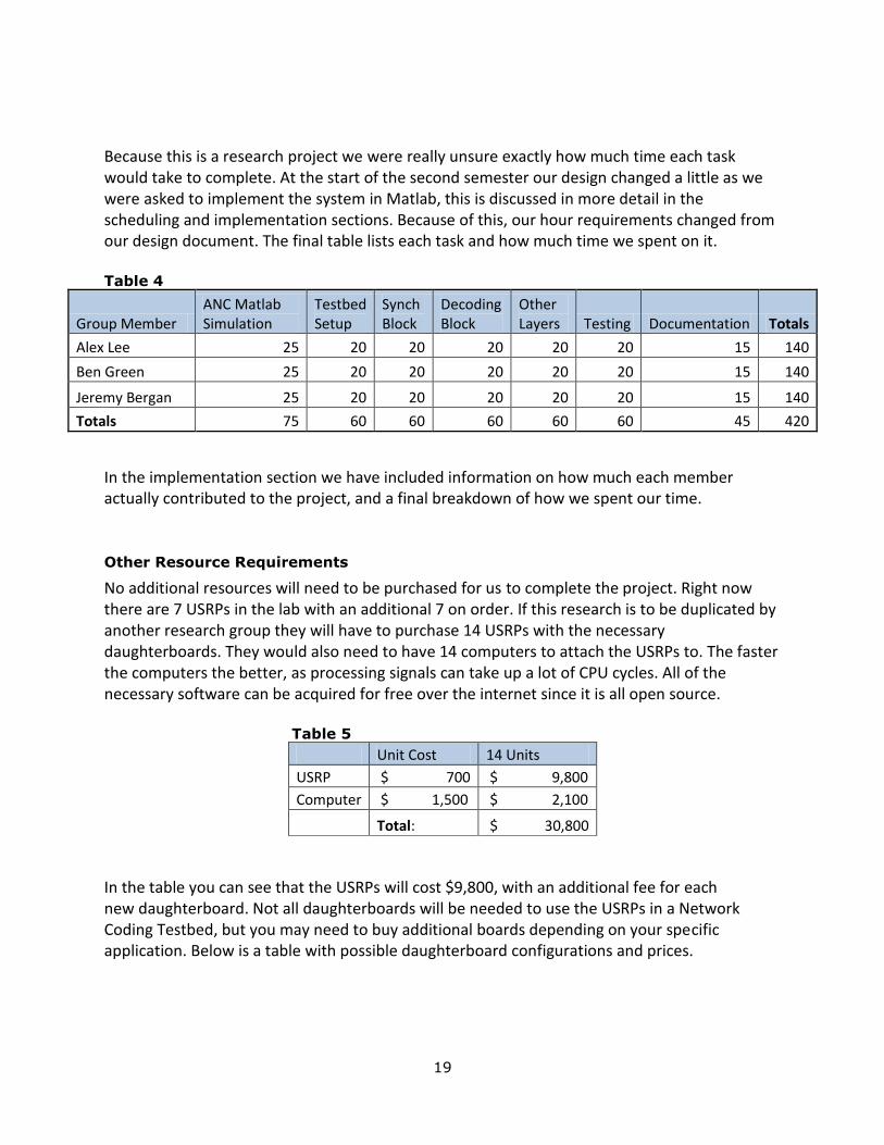
Because this is a research project we were really unsure exactly how much time each task would take to complete. At the start of the second semester our design changed a little as we were asked to implement the system in Matlab, this is discussed in more detail in the scheduling and implementation sections. Because of this, our hour requirements changed from our design document. The final table lists each task and how much time we spent on it.
Table 4
Group Member ANC Matlab Simulation
Testbed Setup
Synch Block
Decoding Block
Other Layers Testing Documentation Totals
Alex Lee 25 20 20 20 20 20 15 140
Ben Green 25 20 20 20 20 20 15 140
Jeremy Bergan 25 20 20 20 20 20 15 140
Totals 75 60 60 60 60 60 45 420
In the implementation section we have included information on how much each member actually contributed to the project, and a final breakdown of how we spent our time.
Other Resource Requirements
No additional resources will need to be purchased for us to complete the project. Right now there are 7 USRPs in the lab with an additional 7 on order. If this research is to be duplicated by another research group they will have to purchase 14 USRPs with the necessary daughterboards. They would also need to have 14 computers to attach the USRPs to. The faster the computers the better, as processing signals can take up a lot of CPU cycles. All of the necessary software can be acquired for free over the internet since it is all open source.
Table 5
Unit Cost 14 Units
USRP $ 700 $ 9,800
Computer $ 1,500 $ 2,100
Total: $ 30,800
In the table you can see that the USRPs will cost $9,800, with an additional fee for each new daughterboard. Not all daughterboards will be needed to use the USRPs in a Network Coding Testbed, but you may need to buy additional boards depending on your specific application. Below is a table with possible daughterboard configurations and prices.
20
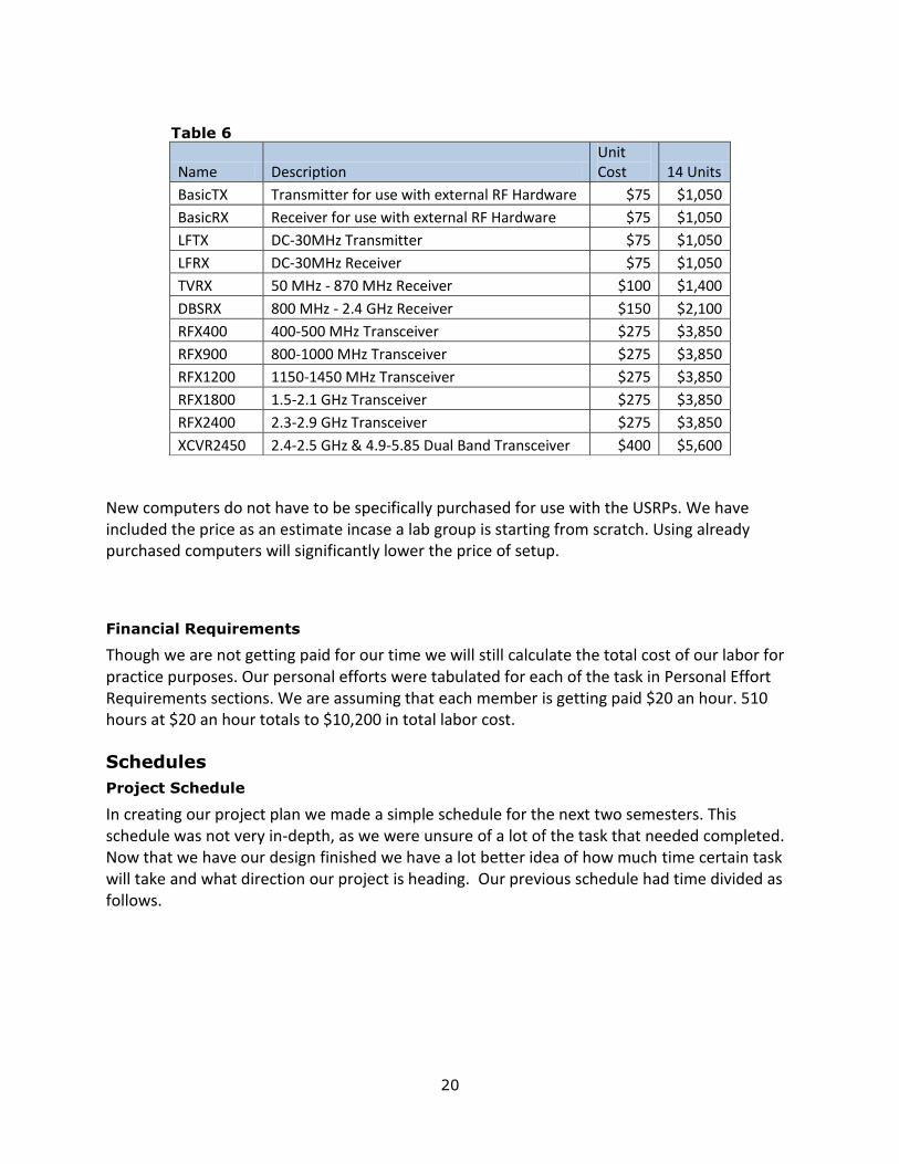
Table 6
Name Description Unit Cost 14 Units
BasicTX Transmitter for use with external RF Hardware $75 $1,050
BasicRX Receiver for use with external RF Hardware $75 $1,050
LFTX DC-30MHz Transmitter $75 $1,050
LFRX DC-30MHz Receiver $75 $1,050
TVRX 50 MHz - 870 MHz Receiver $100 $1,400
DBSRX 800 MHz - 2.4 GHz Receiver $150 $2,100
RFX400 400-500 MHz Transceiver $275 $3,850
RFX900 800-1000 MHz Transceiver $275 $3,850
RFX1200 1150-1450 MHz Transceiver $275 $3,850
RFX1800 1.5-2.1 GHz Transceiver $275 $3,850
RFX2400 2.3-2.9 GHz Transceiver $275 $3,850
XCVR2450 2.4-2.5 GHz & 4.9-5.85 Dual Band Transceiver $400 $5,600
New computers do not have to be specifically purchased for use with the USRPs. We have included the price as an estimate incase a lab group is starting from scratch. Using already purchased computers will significantly lower the price of setup.
Financial Requirements
Though we are not getting paid for our time we will still calculate the total cost of our labor for practice purposes. Our personal efforts were tabulated for each of the task in Personal Effort Requirements sections. We are assuming that each member is getting paid $20 an hour. 510 hours at $20 an hour totals to $10,200 in total labor cost.
Schedules
Project Schedule
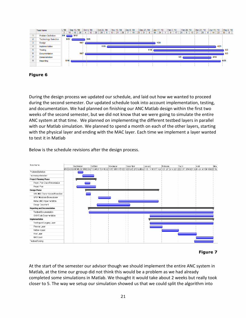
In creating our project plan we made a simple schedule for the next two semesters. This schedule was not very in-depth, as we were unsure of a lot of the task that needed completed. Now that we have our design finished we have a lot better idea of how much time certain task will take and what direction our project is heading. Our previous schedule had time divided as follows.
21
Figure 6
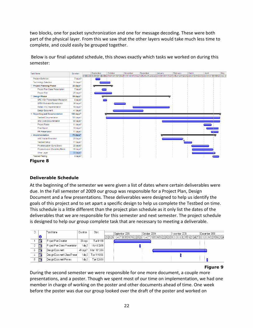
During the design process we updated our schedule, and laid out how we wanted to proceed during the second semester. Our updated schedule took into account implementation, testing, and documentation. We had planned on finishing our ANC Matlab design within the first two weeks of the second semester, but we did not know that we were going to simulate the entire ANC system at that time. We planned on implementing the different testbed layers in parallel with our Matlab simulation. We planned to spend a month on each of the other layers, starting with the physical layer and ending with the MAC layer. Each time we implement a layer wanted to test it in Matlab Below is the schedule revisions after the design process.
Figure 7
At the start of the semester our advisor though we should implement the entire ANC system in Matlab, at the time our group did not think this would be a problem as we had already completed some simulations in Matlab. We thought it would take about 2 weeks but really took closer to 5. The way we setup our simulation showed us that we could split the algorithm into
22
two blocks, one for packet synchronization and one for message decoding. These were both part of the physical layer. From this we saw that the other layers would take much less time to complete, and could easily be grouped together.
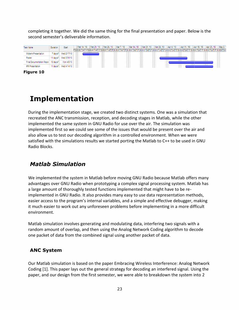
Below is our final updated schedule, this shows exactly which tasks we worked on during this semester:
Figure 8
Deliverable Schedule
At the beginning of the semester we were given a list of dates where certain deliverables were due. In the Fall semester of 2009 our group was responsible for a Project Plan, Design Document and a few presentations. These deliverables were designed to help us identify the goals of this project and to set apart a specific design to help us complete the Testbed on time. This schedule is a little different than the project plan schedule as it only list the dates of the deliverables that we are responsible for this semester and next semester. The project schedule is designed to help our group complete task that are necessary to meeting a deliverable.
Figure 9
During the second semester we were responsible for one more document, a couple more presentations, and a poster. Though we spent most of our time on implementation, we had one member in charge of working on the poster and other documents ahead of time. One week before the poster was due our group looked over the draft of the poster and worked on
23
completing it together. We did the same thing for the final presentation and paper. Below is the second semester’s deliverable information.
Implementation
During the implementation stage, we created two distinct systems. One was a simulation that recreated the ANC transmission, reception, and decoding stages in Matlab, while the other implemented the same system in GNU Radio for use over the air. The simulation was implemented first so we could see some of the issues that would be present over the air and also allow us to test our decoding algorithm in a controlled environment. When we were satisfied with the simulations results we started porting the Matlab to C++ to be used in GNU Radio Blocks.
Matlab Simulation
We implemented the system in Matlab before moving GNU Radio because Matlab offers many advantages over GNU Radio when prototyping a complex signal processing system. Matlab has a large amount of thoroughly tested functions implemented that might have to be re-implemented in GNU Radio. It also provides many easy to use data representation methods, easier access to the program’s internal variables, and a simple and effective debugger, making it much easier to work out any unforeseen problems before implementing in a more difficult environment. Matlab simulation involves generating and modulating data, interfering two signals with a random amount of overlap, and then using the Analog Network Coding algorithm to decode one packet of data from the combined signal using another packet of data.
ANC System
Our Matlab simulation is based on the paper Embracing Wireless Interference: Analog Network Coding [1]. This paper lays out the general strategy for decoding an interfered signal. Using the paper, and our design from the first semester, we were able to breakdown the system into 2
Figure 10

24
different phases: transmission and reception. The transmission step is very general, while the reception step is more novel. Below we will discuss each step in detail.
Transmission
To start we generated two signals with 1,024 random data bits of payload and a 64 bit pilot sequence. The signal is framed so there is a pilot sequence followed by the payload followed by the reversed pilot sequence. The pilot bits are used for synchronization at later steps. It is important that both signals are being transmitted using the same sampling rate. Now each of the framed signals is modulated using MSK and are up-sampled. The two signals are combined with a random amount of overlap between them.
Reception
For the reception process we will assume that the two signals from above are labeled A and B. A is known to the receiver while B is unknown, so our goal is to find out what signal B is. The same decoding process can be used by both the sender of A and B to find the unknown signals, B will just need to switch the steps for A and B is the steps below. Reception can be broken down into three steps: sampling, channel measurements, and decoding.
1. After the signal is transmitted, the receiver will first find the sample time for known signal A and unknown signal B. In order to find the sample time, the receiver calculates the sample index by cross correlating the modulated pilot bits with the received signal in order to locate starting point of the actual interfered data signal with known pilot bits. We reconstruct the time-shifted version of signal A so that we would know the amplitude and phase of A at the sample times for B. Then, we sample the received signal.
2. When we sample the received signal, we calculate the variance of the signal over a
sliding window in order to find out where the interference starts and ends by comparing to a threshold. The amplitude of the individual signals is measured by averaging the received amplitude at the small sections at the beginning and end of the signal where the two signals are not interfering.
3. Using the individual amplitudes of A and B, and the received signal, we can determine possible phases of A and B that would result in A and B summing to the received signal. We then use our knowledge of the correct value of A (the signal sent by this node) to determine the correct phase for B. Knowing the phase for B allows us to demodulate the signal, retrieving the desired data.

25
Testing & Simulation Results
For testing in Matlab, two random payloads are generated and are appended with an
appropriate pilot sequence. The signals are up-sampled as if being transmitted, and added
together with a random offset. The combined signal is run through the reception chain,
plotting various important sets of data.
Figure 11: The beginning and end of interference is clearly detected using the
variance of the signal.
Figure 12: The correct sample times for A and B are clearly seen in the cross-
correlation of the known pilot sequence and the received signal
26
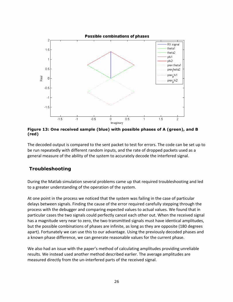
Figure 13: One received sample (blue) with possible phases of A (green), and B
(red) The decoded output is compared to the sent packet to test for errors. The code can be set up to be run repeatedly with different random inputs, and the rate of dropped packets used as a general measure of the ability of the system to accurately decode the interfered signal.
Troubleshooting
During the Matlab simulation several problems came up that required troubleshooting and led to a greater understanding of the operation of the system. At one point in the process we noticed that the system was failing in the case of particular delays between signals. Finding the cause of the error required carefully stepping through the process with the debugger and comparing expected values to actual values. We found that in particular cases the two signals could perfectly cancel each other out. When the received signal has a magnitude very near to zero, the two transmitted signals must have identical amplitudes, but the possible combinations of phases are infinite, as long as they are opposite (180 degrees apart). Fortunately we can use this to our advantage. Using the previously decoded phases and a known phase difference, we can generate reasonable values for the current phase. We also had an issue with the paper’s method of calculating amplitudes providing unreliable results. We instead used another method described earlier. The average amplitudes are measured directly from the un-interfered parts of the received signal.

27
Throughout the Matlab simulation, we gained a better understanding of how an Analog Network Coding system works. We didn't expect testing the system to take so much time. The Matlab simulation helped when we implement the testbed in GNU Radio. We could organize the system easily and some of the functions that we implemented in Matlab can be easily converted to GNU Radio system.
GNU Radio Implementation
After we completed the Matlab simulation and were satisfied with the results, we started implementing the code in GNU Radio. Before we were able to jump into writing the code there were a couple of tasks to complete:
1. Setup an environment for source code and compilation. 2. Setup a repository to keep track of code changes. 3. Decide how we wanted to split the Matlab code up for implementation. 4. Choose members to be responsible for each section of code. 5. Decide how we wanted to demo the system. 6. Choose a user interface.
To compile the C++ blocks, GNU Radio uses autotools. This automatically creates Makefiles used to compile the code, and can be very helpful when lots of files are involved. Since none of our members had experience with this system we had to spend some time learning how to set up a compilation directory for the code. GNU radio blocks are connected together using python. The interface that is used is called SWIG. SWIG allows python to use C++ code, by giving it access to different functions you write in C++. All of the SWIG information is contained in a .i file, which autotools uses to create the python code. For a more in-depth discussion on the compilation process please view Appendix A. Since we wanted to keep track of all our coding changes we set up a repository. In the first semester we used the network space provided for senior design students. This was nice for saving documents, but didn’t allow us to view changes to code, or allow multiple users to edit a piece of code at the same time. This also allows us to share the code with senior design groups that will be expanding on our code in the future. Our repository is located at:
https://source.ece.iastate.edu/svn/sd-may10-08
The next major step was to decide how we wanted to split up the code for implementation. It took us longer than we expected to finish the ANC simulation and setup a coding environment, so we wanted to make sure that however we split it we could work on the code in parallel. This would allow us to work on multiple parts at the same time.
28
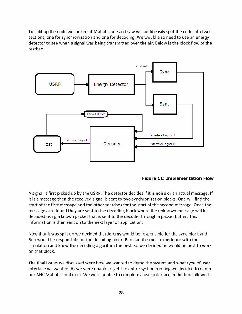
To split up the code we looked at Matlab code and saw we could easily split the code into two sections, one for synchronization and one for decoding. We would also need to use an energy detector to see when a signal was being transmitted over the air. Below is the block flow of the testbed.
Figure 11: Implementation Flow
A signal is first picked up by the USRP. The detector decides if it is noise or an actual message. If it is a message then the received signal is sent to two synchronization blocks. One will find the start of the first message and the other searches for the start of the second message. Once the messages are found they are sent to the decoding block where the unknown message will be decoded using a known packet that is sent to the decoder through a packet buffer. This information is then sent on to the next layer or application. Now that it was split up we decided that Jeremy would be responsible for the sync block and Ben would be responsible for the decoding block. Ben had the most experience with the simulation and knew the decoding algorithm the best, so we decided he would be best to work on that block. The final issues we discussed were how we wanted to demo the system and what type of user interface we wanted. As we were unable to get the entire system running we decided to demo our ANC Matlab simulation. We were unable to complete a user interface in the time allowed.
29
Sync Block
The sync block consists of the task described in the 1st step of the reception process as described in the Matlab simulation section. All GNU Radio blocks have a constructor, forecaster, and general work section. The constructor instantiates the block and sets up anything that may be used throughout the life of the block. If there is anything that needs calculated and will stay consistent throughout the life of a block here is where it is done. The forecaster tells a block if it has enough data to insure that the inputs are valid, while general work is where the actual signal processing occurs. These sections are consistent across all of our blocks. When this block is instantiated a couple of things happen. First the samples per symbol, start, and end sampling times are passed in and block. The start and end times determine which pilot sequence the block will synchronize too. In Figure 11 you can see that two of these blocks are instantiated, one finds the first pilot sequence, while the other finds the offset of the interfered signal. Next the pilot sequence is modulated and upsampled. The upsampled pilot sequence is then used as the taps for a filter. The filter can then be used in the body of the block for cross correlation and synchronization purposes. When this is done in the constructor it only processes it once, and the same taps can be used every time a signal passes through the block. The general work function contains code that will be run on each signal that passes through the block. Simply put, the block uses a filter to cross correlate the pilot sequence with the received signal to find where the offset is between the two interfered signals. After the offset is found the signal is sampled and sent on to the decoding block.
Decoding Block
The decoding block consists of the 2nd and 3rd steps of the reception process as described in the Matlab simulation section. There is only one decoding block instantiated in our system. Instantiating the block sets up a filter and also a packet buffer. This packet buffer is used to store messages that the computer has been sending. Because GNU Radio only allows one type of input to the block we needed to think of a way in which we could pass known packets to the decoding block which takes complex packets as input. A packet buffer allows us to do this. In the general work method our first task is to demodulate each signal and determine if one of them is a known packet. This is important as we must know one of the packets to demodulate
30
the unknown packet. If we find the known packet we can move onto channel measurements and corrections. Channel measurements are needed to determine if the two packets samples line up correctly. First the known packet is received from the buffer, and then the known data is modulated. By using a filter the known data is interpolated, then resampled. The final step is to decode the interfered signal. This is the 3rd step in the Matlab simulation and is close to the same, the only difference here is that after the interfered part is decoded the uninterfered ending is decoded using a simple MSK demodulator. After the unknown message is decoded completely it is sent on to the Host layer where the information can be used by other applications or systems.
Energy Detector
For this block we were able to use some code already in GNU Radio. This block looked at the information coming into the USRP. If the signal went over a certain threshold then the incoming samples would be saved. Once the signal went below the threshold it quit receiving samples. The block would then look at the samples. If they were a correctly interfered signal we put them into a packet and sent them off to the sync blocks.
MSK
This file contains helper functions that are used throughout the different blocks and at different places in the system. Its main functions are a MSK modulator and demodulator. It also contains functions to sample and upsample a signal. The modulator takes in a byte array and modulates this signal. This is used in the sync and decoding block. The demodulator is given an array of complex figures and outputs a byte array.
Testing
To test the blocks we used python scripts. We created input and output that should match, then used the script to link blocks together to test if our input and output matched. We used a similar process for each block. When we got them all working we connected them as in Figure 11 and made sure the input and output were correct again. This is a non-trivial step, as the framework of GNU radio requires that the C++ code must be written completely, along with the python code to even begin testing. Generating the correct input and outputs to test the blocks is also hard, so the first step in testing was to write code to generate this data.
31
During the test phase we wrote different python test scripts that created input to be tested in different blocks. One such module, named packet.py, creates a packet that is 1,060 bytes long. This packet contains the pilot sequence, header, payload, and reversed head and pilot. This is the format that our system is expecting. If not assigned the module will create a random payload, but it can also be assigned known data that can be used at a different layer. The module can output the data in byte format or also as an array of bits. Other modules at the host level were written that could generate different information used for validation of the blocks. As of April 28th, 2010 we were unable to test the entire system over the air. We are still testing each block individually. The MSK block should function correctly as it has been tested completely. We are still writing test code for the decoding and sync block, as stated above this is a non-trivial step and took much longer time than we thought it would.
Issues
The process of porting from Matlab to C++ was much more complicated that we originally thought. We were presented with issues in C++ that we never had to think about in the Matlab simulation. We encountered issues with memory allocation, cases that occur outside a controlled environment, implementing algorithms that were implemented for us in Matlab, as well as compiling and integrating our code with existing GNU Radio code.
Evaluation
During the second semester the scope of our project changed many times. Our original goal was to create a testbed that would allow a user to switch between different network and modulation schemes, but the testbed ended up only implementing Analog Network Coding. Our group was really unsure of the difficulty or time requirements it would take to implement our original goal, this made it much harder during the planning and design process. During the second semester we started development on the ANC simulation in Matlab, this ended up taking longer than initially assumed, but did provided important insight into the practical implementation of the algorithm. Because the simulation took longer than expected we had to change what we wanted our testbed to do. We decide to just implement point to point ANC, and use only a very simple MAC and Network layer. Compiling the C++ code turned into a non-trivial step and caused us to have even less time on the implementation. We did finish coding the testbed and started working on testing the system.
32
Testing in a non-trivial stage and we were unable to complete testing each block during the semester. We did accomplish many things these semesters though:
1. Designed a Testbed that implements Analog Network Coding. 2. Simulated a point to point transmission using Analog Network Coding in Matlab. 3. Created a directory to compile GNU Radio Source Code. 4. Wrote and compiled GNU Radio code to be used in a simple ANC system. 5. Wrote and tested GNU Radio code to use MSK to modulate and demodulate a signal.
Lessons Learned
During these semesters we learned a lot about Network Coding, GNU Radio, and Matlab. This technical information will be helpful in the future, but the main things we learned were about project management. An important thing we learned was that it is very important to start prototyping early on. We did do some Matlab simulations, but we really needed to start working with GNU Radio earlier than we did. There is a system known as GRC that allows you to visually link GNU Radio block together. We worked some with this, but it did not prepare us for coding actual blocks. Writing and testing code is not easy and provided us with many difficulties. If we had attempted this earlier we may have been more prepared to put the entire system together at the end. It is very hard to manage time for research projects, but you need to make sure if you fail completing one task on time it does not stop progress on your entire project. We spent a lot longer creating our ANC simulation in Matlab than we originally thought we would. We spent about half the semester creating it, and even more time refining it. Though this did not completely stop progress on other tasks, it did slow it. We should have planned better for cases like this. Be prepared for the scope of your project to change. Our project changed due to time and software restrictions. We were lucky enough that this did not ruin our entire project, but we knew that the scope could easily change and we planned accordingly.
33
Closing Summary
In closing, current network protocols do not use certain aspects of the network to their fullest extent. The topology of a network can give us clues as to how data can be most efficiently transmitted, and how, by mixing information intelligently, bandwidth can be more efficiently used. This is the field of study of network coding. We used network coding to design a testbed that implements Analog Network Coding to send and receive information. We then used Matlab to simulate our system and attempted to implement the system in GNU Radio. Though we did not get our system to work over the air, we have written code to run the ANC algorithm at the physical layer and have learned a lot about the GNU Radio system.
34
Project Team Information
Client/faculty advisor
Aditya Ramamoorthy Office Address: 3222 Coover Telephone Number: (515) 294-1583 [email protected]
Additional contact: Shizheng Li Office Address: 3133 Coover [email protected]
Student Team Information
Jeremy Bergan Major: Computer Engineering Address: 412 Welsh Ave. Apt #2 Phone number: (563) 880-8726 [email protected] Ben Green Major: Computer Engineering Address: 4327 Frederiksen Ct Phone Number: (319) 899-4534 [email protected]
Alex Lee Major: Electrical Engineering Address: 2624 Kent Ave unit 103 Phone number: (515) 520-1823 [email protected]
35
References
[1] Sachin Katti, Shyamnath Gollakota, Dina Kattabi, Embracing wireless interference: Analog Network Coding, in ACM SIGCOMM Computer Communication Review v.37, n.4, pp 397 – 408, October 2007
[2] Sachin Katti, Hariharan Rahul, Wenjun Hu, Dina Katabi, Murial Medard, Jon Crowcroft, XORs in the air: practical wireless network coding, IEEE/ACM Transactions on Networking, v.16, n.3, June 2008 [3] Philip A. Chou, Yunnan Wu, and Kamal Jain, Practical Network Coding, Allerton Conference on Communication, Control, and Computing
[4] Fragouli, Christina, Jean-Yves Le Boudec, and Jorg Widmer. "Network Coding: An Instant Primer." ACM SIGCOMM Computer Communication Review. v.3, n.1, Jan. 2006.
[5] Ettus Research LLC. “Sales.” Ettus Research. 14 September 2009. Web. 7 October 2009. http://www.ettus.com/sales.
[6] "Universal Software Radio Peripheral -." Wikipedia, the free encyclopedia. Web. 07 Oct. 2009. http://en.wikipedia.org/wiki/Universal_Software_Radio_Peripheral.
[7] "What is MSK, Minimum Shift Keying Modulation :: Radio-Electronics.Com." Radio-Electronics.Com :: reference tutorials jobs exhibitions books news. Web. 07 Oct. 2009. http://www.radio-electronics.com/info/rf-technology-design/pm-phase-modulation/what-is-msk-minimum-shift-keying-tutorial.php.
[8] "GNU Radio." Web. 10 Oct. 2009. http://gnuradio.org/trac .
[9] "Network coding -." Wikipedia, the free encyclopedia. Web. 05 Dec. 2009. <http://en.wikipedia.org/wiki/Network_coding#Random_Network_Coding>.
[10] "Orthogonal frequency-division multiplexing -." Wikipedia, the free encyclopedia. Web. 05 Dec. 2009. <http://en.wikipedia.org/wiki/OFDM>.
36
[11] "Phase-shift keying -." Wikipedia, the free encyclopedia. Web. 05 Dec. 2009. <http://en.wikipedia.org/wiki/Phase-shift_keying>.
[12] "Quadrature amplitude modulation -." Wikipedia, the free encyclopedia. Web. 05 Dec. 2009. <http://en.wikipedia.org/wiki/Quadrature_amplitude_modulation>. [13] S Katti, D Katabi, Mixit: The Network Meets the Wireless Channel, in MIT CSAIL Technical Reports, September 2007
[14] "Bit error ratio -." Wikipedia, the free encyclopedia. Web. 06 Dec. 2009. <http://en.wikipedia.org/wiki/Bit_error_ratio>.
[15] "Media Access Control -." Wikipedia, the free encyclopedia. Web. 06 Dec. 2009. <http://en.wikipedia.org/wiki/Media_Access_Control>.
37
Appendix A
Compiling GNU Radio Testbed Files
This document is designed to help someone compile C++ GNU Radio Block to be used with the GNU Radio Testbed. After reading this you should understand how to edit the configure.ac and Makefile.am files to successfully compile additional code. Also, you should understand how to set up your own directory for compiling code into GNU Radio. In most cases you will be able to use our testbed compilation directory, but it is important to understand how to modify necessary files as well as add new source to the project. GNU Radio uses the GNU autoconf, automake, and libtool tools to compile its files. These are collectively known as autotools. There are many tutorials out there to explain how to use autotools, one that I found very helpful is located at:
http://www.amath.washington.edu/~lf/tutorials/autoconf/toolsmanual_toc.html
If you need additional information about autotools, or are experiencing problems, this is a good place to look for answers. Another tutorial that is very helpful is that located at:
http://www.gnu.org/software/gnuradio/doc/howto-write-a-block.html
This tutorial gives a brief overview on autotools, as well as covers how to write an actual C++ block. I would recommend looking over this before continuing on with this tutorial. The first four sections are particularly helpful if you are just getting started.
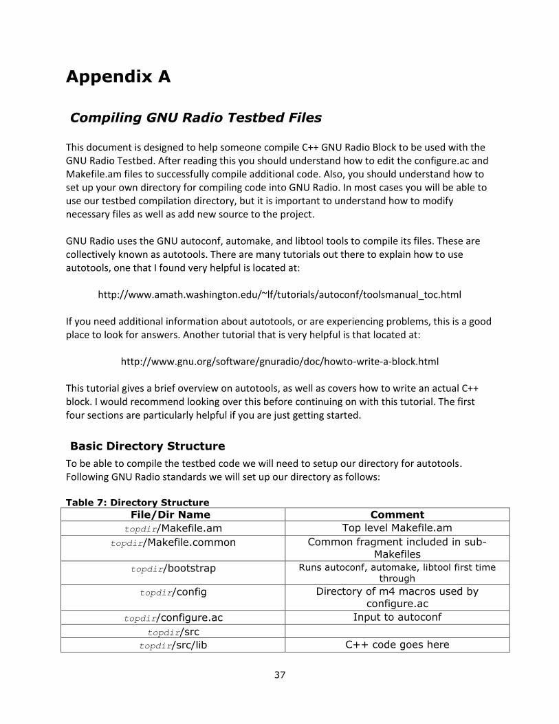
Basic Directory Structure
To be able to compile the testbed code we will need to setup our directory for autotools. Following GNU Radio standards we will set up our directory as follows: Table 7: Directory Structure
File/Dir Name Comment
topdir/Makefile.am Top level Makefile.am
topdir/Makefile.common Common fragment included in sub-
Makefiles
topdir/bootstrap Runs autoconf, automake, libtool first time
through
topdir/config Directory of m4 macros used by
configure.ac
topdir/configure.ac Input to autoconf
topdir/src
topdir/src/lib C++ code goes here
38
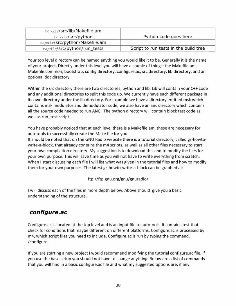
topdir/src/lib/Makefile.am
topdir/src/python Python code goes here
topdir/src/python/Makefile.am
topdir/src/python/run_tests Script to run tests in the build tree
Your top level directory can be named anything you would like it to be. Generally it is the name of your project. Directly under this level you will have a couple of things: the Makefile.am, Makefile.common, bootstrap, config directory, configure.ac, src directory, lib directory, and an optional doc directory. Within the src directory there are two directories, python and lib. Lib will contain your C++ code and any additional directories to split this code up. We currently have each different package in its own directory under the lib directory. For example we have a directory entitled msk which contains msk modulator and demodulator code, we also have an anc directory which contains all the source code needed to run ANC. The python directory will contain block test code as well as run_test script. You have probably noticed that at each level there is a Makefile.am, these are necessary for autotools to successfully create the Make file for you. It should be noted that on the GNU Radio website there is a tutorial directory, called gr-howto-write-a-block, that already contains the m4 scripts, as well as all other files necessary to start your own compilation directory. My suggestion is to download this and to modify the files for your own purpose. This will save time as you will not have to write everything from scratch. When I start discussing each file I will list what was given in the tutorial files and how to modify them for your own purposes. The latest gr-howto-write-a-block can be grabbed at:
ftp://ftp.gnu.org/gnu/gnuradio/
I will discuss each of the files in more depth below. Above should give you a basic understanding of the structure.
configure.ac
Configure.ac is located at the top level and is an input file to autotools. It contains test that check for conditions that maybe different on different platforms. Configure.ac is processed by m4, which script files you need to include. Configure.ac is run by typing the command. /configure. If you are starting a new project I would recommend modifying the tutorial configure.ac file. If you use the base setup you should not have to change anything. Below are a list of commands that you will find in a basic configure.ac file and what my suggested options are, if any.
39
AC_INIT()- This command initializes the configure script. It can be passed as argument the name of your package. The second argument that is passed should be the version number. In our case we pass the version number of the Testbed. AC_PREREQ()-This indicates the version of autoconf that is used.
AC_CONFIG_AUX_DIR() – This macro allows a different directory to be specified for the location of auxiliary scripts.
m4_include() – States the location of additional macros that are listed in separate files.
GR_STANDALONE – According to GNU Radio this handles the bulk of the configure.ac work for an out-of-tree build. AC_CONFIG_COMMANDS() – This specifies additional shell commands to run at the end of config.status, and shell commands to initialize any variables from configure.
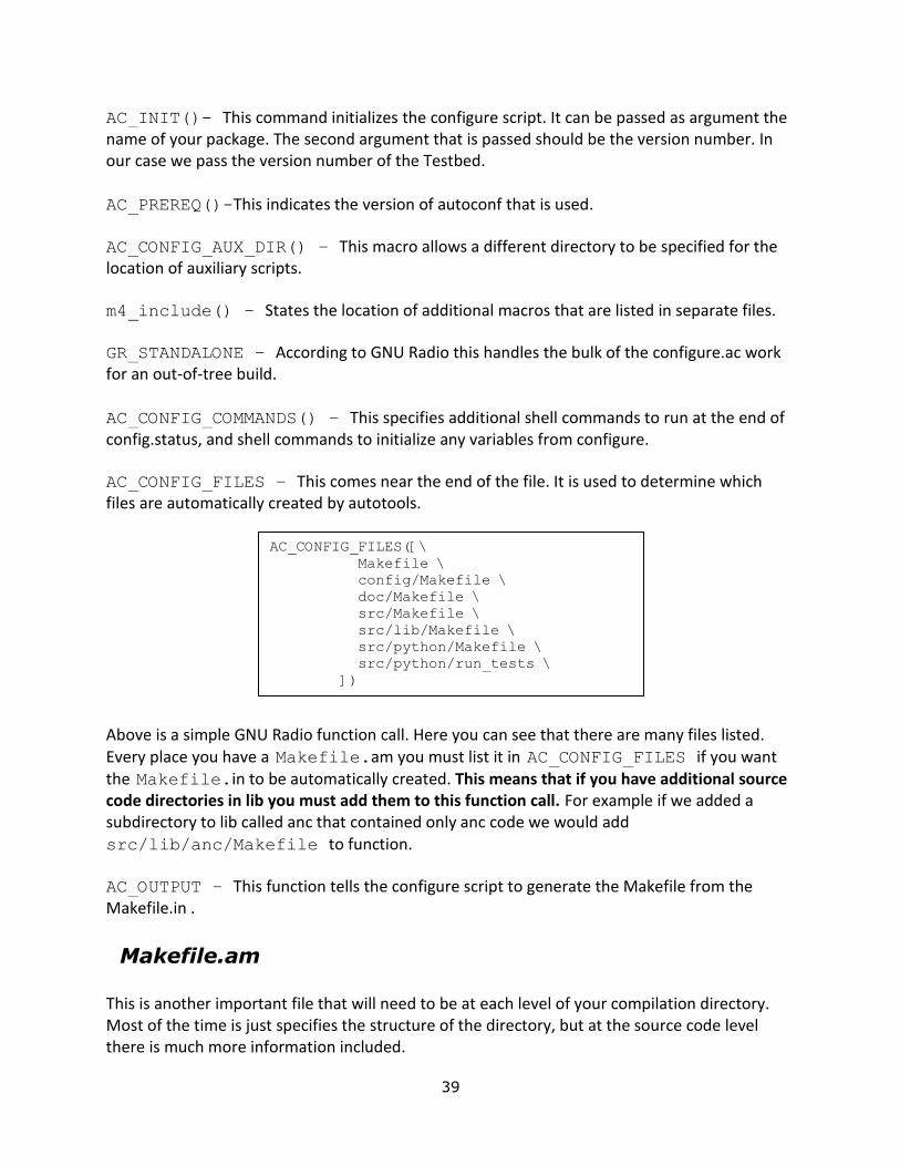
AC_CONFIG_FILES – This comes near the end of the file. It is used to determine which files are automatically created by autotools.
Above is a simple GNU Radio function call. Here you can see that there are many files listed. Every place you have a Makefile.am you must list it in AC_CONFIG_FILES if you want the Makefile.in to be automatically created. This means that if you have additional source code directories in lib you must add them to this function call. For example if we added a subdirectory to lib called anc that contained only anc code we would add
src/lib/anc/Makefile to function.
AC_OUTPUT – This function tells the configure script to generate the Makefile from the Makefile.in .
Makefile.am
This is another important file that will need to be at each level of your compilation directory. Most of the time is just specifies the structure of the directory, but at the source code level there is much more information included.
AC_CONFIG_FILES([\
Makefile \
config/Makefile \
doc/Makefile \
src/Makefile \
src/lib/Makefile \
src/python/Makefile \
src/python/run_tests \
])
40
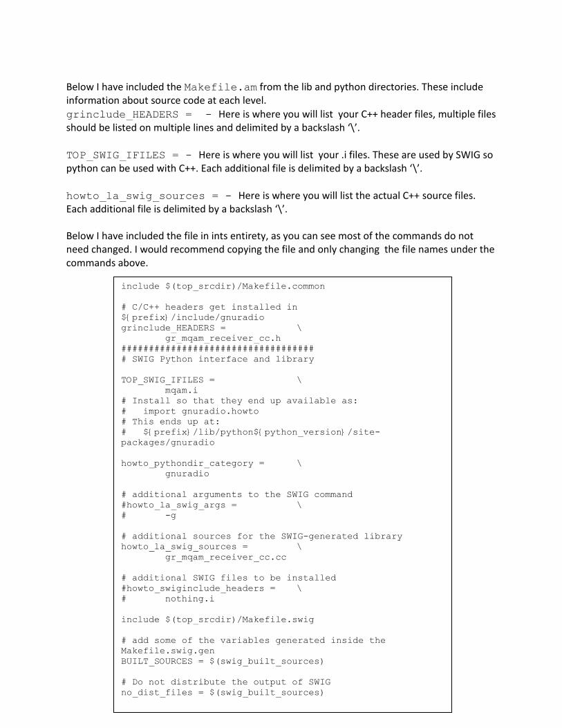
Below I have included the Makefile.am from the lib and python directories. These include information about source code at each level. grinclude_HEADERS = - Here is where you will list your C++ header files, multiple files should be listed on multiple lines and delimited by a backslash ‘\’.
TOP_SWIG_IFILES = - Here is where you will list your .i files. These are used by SWIG so python can be used with C++. Each additional file is delimited by a backslash ‘\’.
howto_la_swig_sources = - Here is where you will list the actual C++ source files. Each additional file is delimited by a backslash ‘\’.
Below I have included the file in ints entirety, as you can see most of the commands do not need changed. I would recommend copying the file and only changing the file names under the commands above.
include $(top_srcdir)/Makefile.common
# C/C++ headers get installed in
${prefix}/include/gnuradio
grinclude_HEADERS = \
gr_mqam_receiver_cc.h
###################################
# SWIG Python interface and library
TOP_SWIG_IFILES = \
mqam.i
# Install so that they end up available as:
# import gnuradio.howto
# This ends up at:
# ${prefix}/lib/python${python_version}/site-
packages/gnuradio
howto_pythondir_category = \
gnuradio
# additional arguments to the SWIG command
#howto_la_swig_args = \
# -g
# additional sources for the SWIG-generated library
howto_la_swig_sources = \
gr_mqam_receiver_cc.cc
# additional SWIG files to be installed
#howto_swiginclude_headers = \
# nothing.i
include $(top_srcdir)/Makefile.swig
# add some of the variables generated inside the
Makefile.swig.gen
BUILT_SOURCES = $(swig_built_sources)
# Do not distribute the output of SWIG
no_dist_files = $(swig_built_sources)
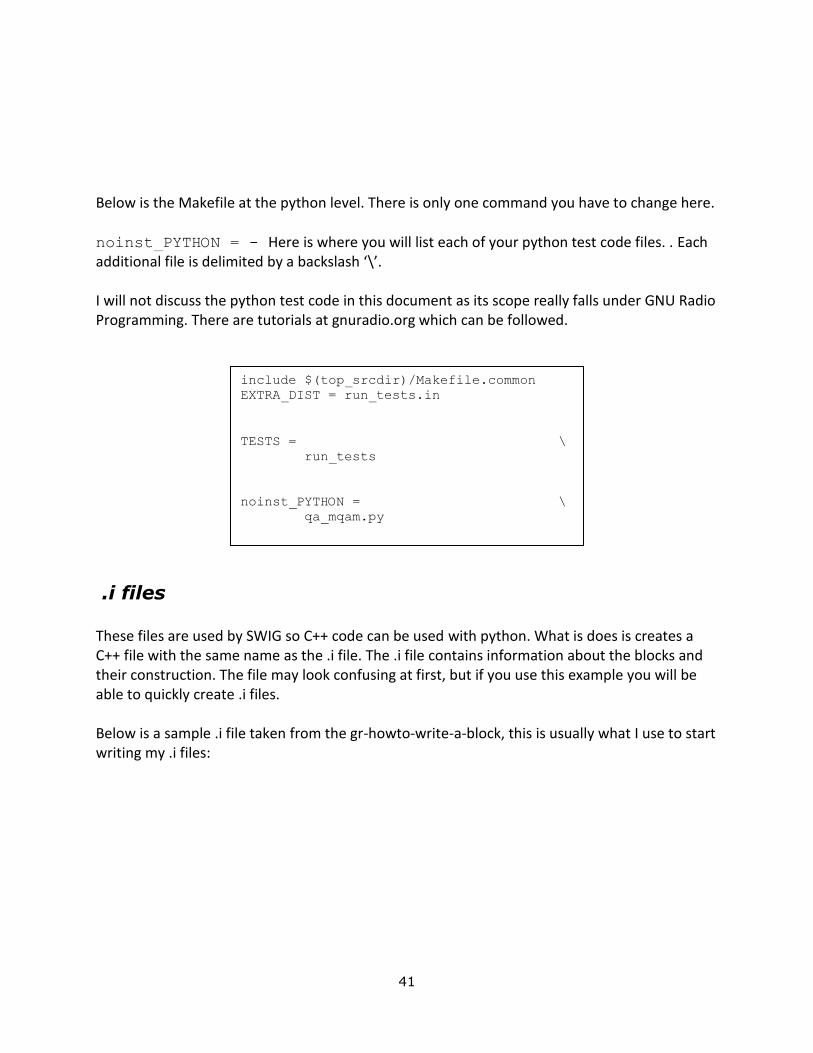
41
Below is the Makefile at the python level. There is only one command you have to change here. noinst_PYTHON = - Here is where you will list each of your python test code files. . Each additional file is delimited by a backslash ‘\’.
I will not discuss the python test code in this document as its scope really falls under GNU Radio Programming. There are tutorials at gnuradio.org which can be followed.
.i files
These files are used by SWIG so C++ code can be used with python. What is does is creates a C++ file with the same name as the .i file. The .i file contains information about the blocks and their construction. The file may look confusing at first, but if you use this example you will be able to quickly create .i files. Below is a sample .i file taken from the gr-howto-write-a-block, this is usually what I use to start writing my .i files:
include $(top_srcdir)/Makefile.common
EXTRA_DIST = run_tests.in
TESTS = \
run_tests
noinst_PYTHON = \
qa_mqam.py
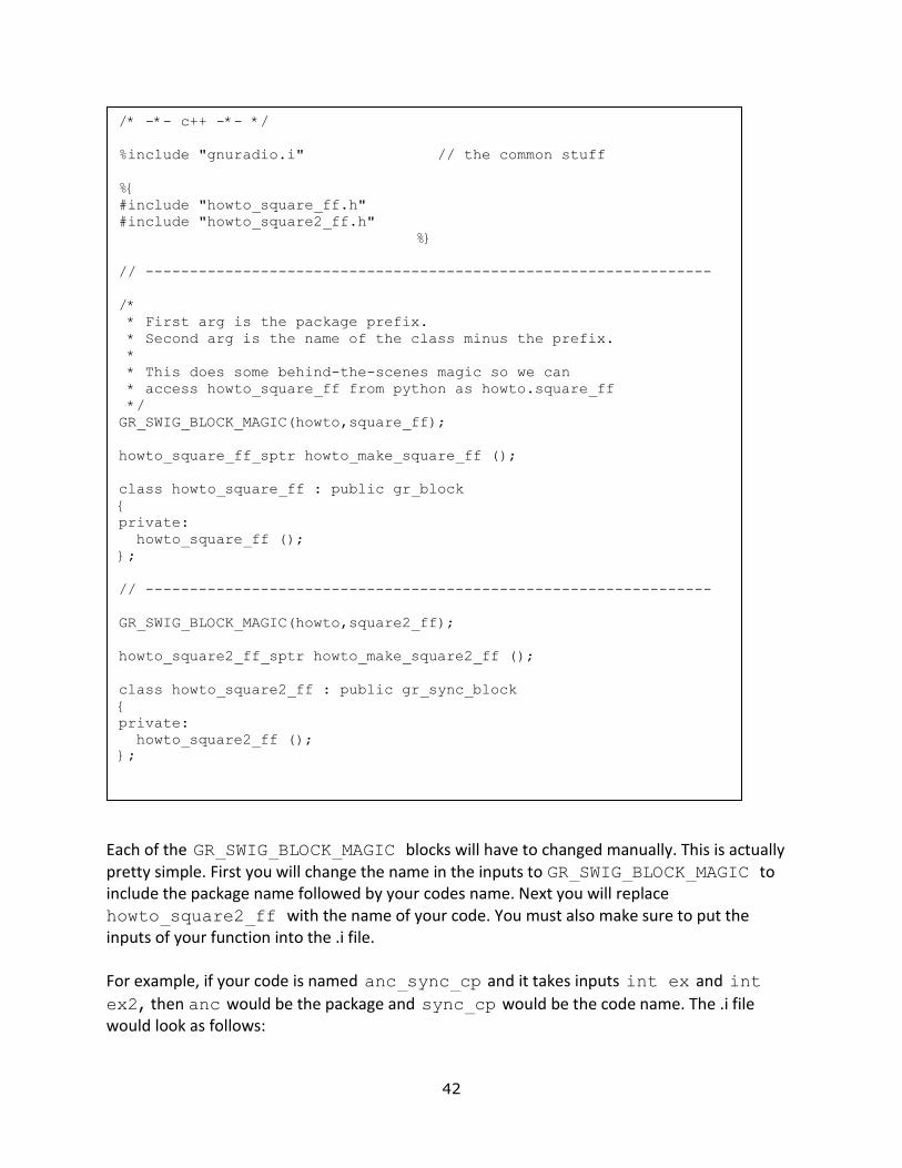
42
Each of the GR_SWIG_BLOCK_MAGIC blocks will have to changed manually. This is actually pretty simple. First you will change the name in the inputs to GR_SWIG_BLOCK_MAGIC to include the package name followed by your codes name. Next you will replace
howto_square2_ff with the name of your code. You must also make sure to put the inputs of your function into the .i file.
For example, if your code is named anc_sync_cp and it takes inputs int ex and int
ex2, then anc would be the package and sync_cp would be the code name. The .i file would look as follows:
/* -*- c++ -*- */
%include "gnuradio.i" // the common stuff
%{
#include "howto_square_ff.h"
#include "howto_square2_ff.h"
%}
// ----------------------------------------------------------------
/*
* First arg is the package prefix.
* Second arg is the name of the class minus the prefix.
*
* This does some behind-the-scenes magic so we can
* access howto_square_ff from python as howto.square_ff
*/
GR_SWIG_BLOCK_MAGIC(howto,square_ff);
howto_square_ff_sptr howto_make_square_ff ();
class howto_square_ff : public gr_block
{
private:
howto_square_ff ();
};
// ----------------------------------------------------------------
GR_SWIG_BLOCK_MAGIC(howto,square2_ff);
howto_square2_ff_sptr howto_make_square2_ff ();
class howto_square2_ff : public gr_sync_block
{
private:
howto_square2_ff ();
};

43
I usually have one .i file for each package, and name the file packagename.i. If you only
have one file in your package you can delete the duplicate GR_SWIG_BLOCK_MAGIC block or add more in the same way as above if you have more files.
run_tests
This is an important file that is located in the python directory. Its job is to find all of the test files in the directory, run them, and display the results of the test. There is nothing that needs to be changed or edited as source files are added, but it is good to understand what it does.
How to compile once setup
Now that you have the configure.ac setup and all of the Makefile.am complete you can compile your code. The basic way to compile the code is the type the three commands:
Bootstrap is a simple script that runs autoconf, automake, and libtools the first time you compile. I would recommend running bootstrap anytime you make changes to your Makefiles or .i files. Configure completes the rest of the configuration, and make compiles your project.
Once you have compile your project and want to use the code there is an additional step that needs to be taken before you can import your code. In each of the source code directories there will be a .lib folder. This folder contains the C++ byte code. You will need to copy any code ending in .so from this directory to the directory directly above it. For example, if we just compile our code and had the source and .i file in a directory called anc there would also be a
./bootstrap
./configure
make
// ----------------------------------------------
------------------
GR_SWIG_BLOCK_MAGIC(anc,sync_cp);
anc_cync_cp_sptr anc_make_sync_cp (int ex, int
ex2);
class anc_sync_cp : public gr_sync_block
{
private:
anc_sync_cp (int ex, int ex2);
};

44
folder called .lib in anc. We would need to enter .lib and copy anc.so and place the copy directly in anc. This will allow us to import the code into our python test scripts.
This is the simple chain of commands that needs to be run to compile the project. Once it has been compiled there are many other things you can do. I would recommend visiting the automake tutorial for more information. One of the most important commands is make
check. This runs the python test scripts that test your GNU Radio block.