network fault conditions.ppt 3.pdf
TRANSCRIPT

7/28/2019 Network Fault Conditions.ppt 3.pdf
http://slidepdf.com/reader/full/network-fault-conditionsppt-3pdf 1/78
# 1. Network Fault Conditions
# 2. Balanced Faults
# 3. Unbalanced Faults

7/28/2019 Network Fault Conditions.ppt 3.pdf
http://slidepdf.com/reader/full/network-fault-conditionsppt-3pdf 2/78
Network Fault Conditions -Topics
■ Why to Calculate Fault Currents
■ Fault Types
■ Unbalanced Fault Conditions
■ Symmetrical Vectors
■ Phase Sequence Networks
7/28/2019 Network Fault Conditions.ppt 3.pdf
http://slidepdf.com/reader/full/network-fault-conditionsppt-3pdf 3/78
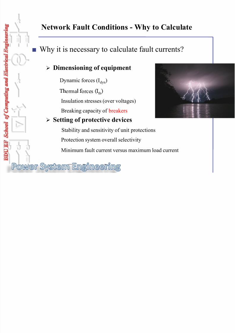
Dimensioning of equipment
Dynamic forces (Idyn)
Network Fault Conditions - Why to Calculate
■ Why it is necessary to calculate fault currents?
erma orces th
Insulation stresses (over voltages)
Breaking capacity of breakers
Setting of protective devicesStability and sensitivity of unit protections
Protection system overall selectivity
Minimum fault current versus maximum load current

7/28/2019 Network Fault Conditions.ppt 3.pdf
http://slidepdf.com/reader/full/network-fault-conditionsppt-3pdf 4/78
Network Fault Conditions - Why to Calculate
■ Why it is necessary to calculate fault currents?
Network stability
Effects the power transfer capacity
Step and touch voltages during earth faults
Control aspects
Allowed and preferred switching combinations

7/28/2019 Network Fault Conditions.ppt 3.pdf
http://slidepdf.com/reader/full/network-fault-conditionsppt-3pdf 5/78
Network Fault Conditions -Topics
■ Why to Calculate Fault Currents
■ Fault Types (Active and Passive faults)
■ Balanced Fault Conditions
■ Unbalanced Fault Conditions
■ Symmetrical Vectors
■ Phase Sequence Networks

7/28/2019 Network Fault Conditions.ppt 3.pdf
http://slidepdf.com/reader/full/network-fault-conditionsppt-3pdf 6/78
Network Fault Conditions - Fault Types
FAULT = a state of abnormality within the network that involves
a electrical failure of a primary component
■ Fault Types
Short circuits (Shunt fault)
Open circuits (Series fault)
Simultaneous faults
Winding faults
7/28/2019 Network Fault Conditions.ppt 3.pdf
http://slidepdf.com/reader/full/network-fault-conditionsppt-3pdf 7/78
Network Fault Conditions - Fault Types
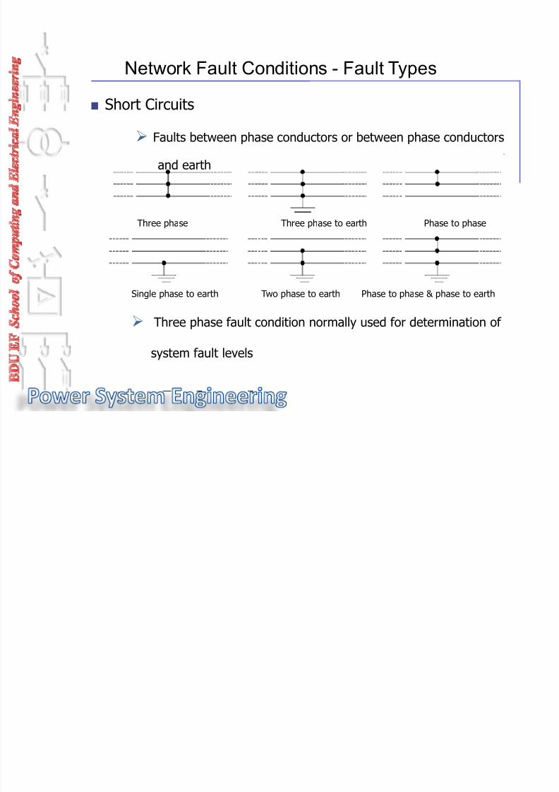
■ Short Circuits
Faults between phase conductors or between phase conductors
and earth
Three phase Three phase to earth Phase to phase
Single phase to earth Two phase to earth Phase to phase & phase to earth
Three phase fault condition normally used for determination of
system fault levels

7/28/2019 Network Fault Conditions.ppt 3.pdf
http://slidepdf.com/reader/full/network-fault-conditionsppt-3pdf 8/78
Network Fault Conditions -Fault Types
Single phase open circuit Two phase open circuit Three phase open circuit
Failure of one or more phases to conduct
■ Open Circuits
Single and two phase open circuits are causing unbalance in the
system, thus risking a damage with rotating plants
■ Simultaneous (multiple) Faults•~
Presence of two or more similar or different kind of faults
somewhere in the power system
For example: double earth fault

7/28/2019 Network Fault Conditions.ppt 3.pdf
http://slidepdf.com/reader/full/network-fault-conditionsppt-3pdf 9/78
Faults which occur on machine and transformer windings Between windings, winding and earth, within winding or a mixture
Network Fault Conditions - Fault Types
■ Winding Faults
Phase to earth Phase to phase Open circuited winding
Short circuited turns

7/28/2019 Network Fault Conditions.ppt 3.pdf
http://slidepdf.com/reader/full/network-fault-conditionsppt-3pdf 10/78
Network Fault Conditions - Topics
■ Why to Calculate Fault Currents
■ Fault Types
■ Balanced Fault Conditions
■ Unbalanced Fault Conditions
■ Symmetrical Vectors
■ Phase Sequence Networks

7/28/2019 Network Fault Conditions.ppt 3.pdf
http://slidepdf.com/reader/full/network-fault-conditionsppt-3pdf 11/78
Network Fault Conditions - Balanced Faults
■ Balanced fault = three phase short circuit
■ Balanced fault = fault current (and voltage) values in all
of the phases are equal in magnitude and symmetrically
° .
■ Balanced values = positive sequence values only

7/28/2019 Network Fault Conditions.ppt 3.pdf
http://slidepdf.com/reader/full/network-fault-conditionsppt-3pdf 12/78
Network Fault Conditions - Unbalanced Faults
■ Unbalanced faults = all other faults except three phase
short circuit
■ Unbalanced fault = fault current (and voltage) values
are different between phases both inma nitude and in hase intervals
■ Unbalance values = positive, negative and zero values

7/28/2019 Network Fault Conditions.ppt 3.pdf
http://slidepdf.com/reader/full/network-fault-conditionsppt-3pdf 13/78
Network Fault Conditions - Topics
■ Why to Calculate Fault Currents
■ Fault Types
■ Balanced Fault Conditions
■ Unbalanced Fault Conditions
■ Symmetrical Vectors
■ Phase Sequence Networks

7/28/2019 Network Fault Conditions.ppt 3.pdf
http://slidepdf.com/reader/full/network-fault-conditionsppt-3pdf 14/78
Network Fault Conditions - Symmetrical Vectors
■ For proper evaluation of unbalanced fault conditions in asymmetrical three phase network
■ A mathematical method
■ Any unbalanced three phase set of current and/or voltagevectors can be re resented b the sum of three sets of
■ Balanced system vectors:- Positive sequence set
•~ - Negative sequence set•~ - Zero sequence set
balanced symmetrical) vectors
■ Unbalanced system situation is shown as a sum of threebalanced systems

7/28/2019 Network Fault Conditions.ppt 3.pdf
http://slidepdf.com/reader/full/network-fault-conditionsppt-3pdf 15/78
■ Divided into symmetrical current components
Network Fault Conditions - Symmetrical Vectors
■ An unsymmetrical current vector presentation
■ Symmetrical components forming the unsymmetrical currents

7/28/2019 Network Fault Conditions.ppt 3.pdf
http://slidepdf.com/reader/full/network-fault-conditionsppt-3pdf 16/78
Network Fault Conditions - Symmetrical Vectors
■ Positive sequence set of vectors
Equal in magnitude
Spaced with 120° intervals
In positive order
■ Ne ative se uence set of vectors
Equal in magnitude
Spaced with 120° intervals
In reversed (negative) order

7/28/2019 Network Fault Conditions.ppt 3.pdf
http://slidepdf.com/reader/full/network-fault-conditionsppt-3pdf 17/78
Network Fault Conditions - Symmetrical Vectors
Zero sequence set of vectors
◙ Equal in magnitude
◙ Equal in phase
Equations
=a a1 a2 a0
Ib = Ib1 + Ib2 + Ib0
Ic = Ic1 + Ic2 + Ic0
Ia
, Ib
, Ic
denote for any unbalanced three phase vectors in positive
sequence phase order
Second subscripts 1,2 and 0 denote for positive, negative and zero
sequence sets

7/28/2019 Network Fault Conditions.ppt 3.pdf
http://slidepdf.com/reader/full/network-fault-conditionsppt-3pdf 18/78
Unbalanced three-phase voltages and their symmetrical components: (a) unbalanced instantaneous
voltages and their phasors; (b) balanced PPS phasors; (c) balanced NPS phasors and (d) ZPS phasors

7/28/2019 Network Fault Conditions.ppt 3.pdf
http://slidepdf.com/reader/full/network-fault-conditionsppt-3pdf 19/78

7/28/2019 Network Fault Conditions.ppt 3.pdf
http://slidepdf.com/reader/full/network-fault-conditionsppt-3pdf 20/78
Network Fault Conditions - Topics
■ Why to Calculate Fault Currents
■ Fault Types
■ Balanced Fault Conditions
■ Unbalanced Fault Conditions
■ Symmetrical Vectors
■ Phase Sequence Networks

7/28/2019 Network Fault Conditions.ppt 3.pdf
http://slidepdf.com/reader/full/network-fault-conditionsppt-3pdf 21/78
■Three phase unbalanced network fault case shown withthree equivalent single phase balanced networks
▲ Symmetrical (balanced) current and voltage vectors lead to phasesequence networks
▲ Balanced faults: positive sequence network only Unbalanced faults:
positive, negative and zero sequence networks
Network Fault Currents - Phase Sequence Networks
▲Connections between the sequence networks (serial, parallel or
combination) depend on the fault case under consideration
▲ E.m.f.s produced by generators are positive sequence voltagesonly, there being no generated negative or zero sequencevoltages in the system

7/28/2019 Network Fault Conditions.ppt 3.pdf
http://slidepdf.com/reader/full/network-fault-conditionsppt-3pdf 22/78

7/28/2019 Network Fault Conditions.ppt 3.pdf
http://slidepdf.com/reader/full/network-fault-conditionsppt-3pdf 23/78
Network Fault Currents - Phase Sequence Networks
Example how to measure sequence impedance
of a transmission line
Positive and negative
sequence impedance
Zero sequence
circuit
Zero sequence
impedance

7/28/2019 Network Fault Conditions.ppt 3.pdf
http://slidepdf.com/reader/full/network-fault-conditionsppt-3pdf 24/78
Overhead lines Z1 = Z2
Zo ≈ 2...3*Z1 (depends on soil, ground wires, etc.)
Cables
Z1≈
Z2
Network Fault Currents - Phase Sequence Networks
o
Transformers
Z1 ≈ Z2 (typically)
Zo
depends highly on connection group (earthing impedance)
Synchronous machines Z1 > Z2
Zo varies largely, Ro > R1, Xo « X1

7/28/2019 Network Fault Conditions.ppt 3.pdf
http://slidepdf.com/reader/full/network-fault-conditionsppt-3pdf 25/78
#1 . Network Fault Conditions
#2 . Balanced Faults
#3 . Unbalanced Faults

7/28/2019 Network Fault Conditions.ppt 3.pdf
http://slidepdf.com/reader/full/network-fault-conditionsppt-3pdf 26/78
Balanced Faults - Topics
■ Fundamentals
■ Network Components
■ Calculation Methods
■ Ехam le #1
■ Ехample #2

7/28/2019 Network Fault Conditions.ppt 3.pdf
http://slidepdf.com/reader/full/network-fault-conditionsppt-3pdf 27/78
Network laws
Ohm's law
U = I x Z
Vector equation
Complex values
Kirchoff's first law
Balanced Faults – Fundamentals
Ia+Ib+Ic+Id = 0
Kirchoff's second law
The vector sum of source voltages effecting a closed loopis equal to the vector sum of voltage drops in the loop
E1+E2+E3 = I1Z1+I2Z2+I3Z3

7/28/2019 Network Fault Conditions.ppt 3.pdf
http://slidepdf.com/reader/full/network-fault-conditionsppt-3pdf 28/78
Balanced Faults - Fundamentals
■ Different stages during the fault
Initial stageI” k initial short circuit current
X” d initial axial reactance of a synchronous machine
Presence of DC-component
Determines the Idyn level (dynamic short circuit level)
Transient stage I’ k transient short circuit current
Suppressing DC-component
X’ d transient axial reactance of a synchronous machine
Steady stageIk steady stage short circuit current
Xd axial synchronous reactance of a synchronous machine
No DC-component present
Determines the Itherm level (thermal short circuit level)

7/28/2019 Network Fault Conditions.ppt 3.pdf
http://slidepdf.com/reader/full/network-fault-conditionsppt-3pdf 29/78
Balanced Faults - Fundamentals
■ DC - component in the short circuit current
Short circuit current with Short circuit current withoutDC-component (DC offset) DC-component
What further away the generating points in the network are, the lessdifference there will be between initial, transient and steady stage currents

7/28/2019 Network Fault Conditions.ppt 3.pdf
http://slidepdf.com/reader/full/network-fault-conditionsppt-3pdf 30/78
Balanced Faults - Fundamentals
■ DC-component in the short circuit current
Magnitude depends on the moment when the fault occurs The suppression time of the DC-component depends the R/X
ratio of the network
■ Peak Current
Peak value hi hest value of the short circuit current
k = 1,02 + 0,98e-~R ~~
Factor varies between 1,0 and 2,0. Usually with HV-networksvalue 1,8 is used
ip = k kx√2 x I"k (ip = peak current)
If I"k ≈ Ik ,then ip = 1,8 x√ 2 x Ik ≈ 2,5 x Ik
with equipment the Idyn level is usually 2,5 times the Itherm leve

7/28/2019 Network Fault Conditions.ppt 3.pdf
http://slidepdf.com/reader/full/network-fault-conditionsppt-3pdf 31/78
Balanced Faults - Topics
■ Fundamentals
■ Network Components
■ Calculation Methods
■ Ехample #1
■ Ехample #2

7/28/2019 Network Fault Conditions.ppt 3.pdf
http://slidepdf.com/reader/full/network-fault-conditionsppt-3pdf 32/78
Balanced Faults - Network Components
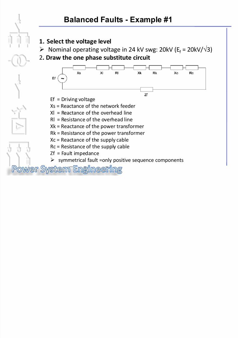
■ One phase representation of the fault case Driving voltage (E)
Nominal phase voltage of the selected level
IEC recommends following factors for the driving voltage whencalculating the maximum current (factor "c"):
UN > 1kV→ E = 1,1 x UN /√3 = , ... ,
Prefault load situation
To be considered as impedances (usually ignored when calculating by hand)
Network components
To be considered as impedances Calculation with complex values
Z = 78Ω∟65° = 32,96+j70,69Ω

7/28/2019 Network Fault Conditions.ppt 3.pdf
http://slidepdf.com/reader/full/network-fault-conditionsppt-3pdf 33/78
Balanced Faults - Network Components
■
Presentation of network components Synchronous generators
Resistive component usually ignored (typically X/R > 10)
Axial reactances used
Effect of X"d , X'd and Xd to be considered case by case
Xd = xd (%) /100 *U2N / SN
Power transformer
Zk = uk (%) /100 *U2N / SN
R k =copper losses = PkN / SN * U2N / SN
Xk = (Z2k – R 2k )
Position of tap changer can be ignored, effects mainly to the load or fault
current division between parallel in feeds

7/28/2019 Network Fault Conditions.ppt 3.pdf
http://slidepdf.com/reader/full/network-fault-conditionsppt-3pdf 34/78
Balanced Faults - Network Components
■ Presentation of network components
Network feeder
Resistive component usually ignored
Often the initial short circuit level is given (Sk3)
X"s = U2s / S"k3
If the initial short circuit reactance of the network is less than half from the short
•~
circuit reactance of the power transformer in between the network and the fault
point, the initial level can be regarded the same as the steady stage level (Xs < 0,5 * Xk )
Overhead line or cable circuits
Resistive component recognized
With lower voltages the effect of conductor heating has to be recognized. Usuallywhen calculating the maximum fault current the temperature of 40°C is used.

7/28/2019 Network Fault Conditions.ppt 3.pdf
http://slidepdf.com/reader/full/network-fault-conditionsppt-3pdf 35/78
Balanced Faults - Network Components
■ Presentation of network components
Unsynchronous motor
supplies fault current during the first 3-5 cycles
usually recognised only when calculating the initial short circuit
current => switchgears Idyn level

7/28/2019 Network Fault Conditions.ppt 3.pdf
http://slidepdf.com/reader/full/network-fault-conditionsppt-3pdf 36/78
Balanced Faults - Topics
■ Fundamentals■ Network Components
■ Calculation Methods
■ Ехample #1 ■ хamp e

7/28/2019 Network Fault Conditions.ppt 3.pdf
http://slidepdf.com/reader/full/network-fault-conditionsppt-3pdf 37/78
Balanced Faults - Calculation Methods
Basic Methods to solve the circuit
Thevenin's theorem
applicable to any linear network
sum of driving voltages can replaced with a single
driving voltage acting in series with a single impedance

7/28/2019 Network Fault Conditions.ppt 3.pdf
http://slidepdf.com/reader/full/network-fault-conditionsppt-3pdf 38/78
Balanced Faults - Calculation Methods
■ Basic Methods to solve the circuit
Superposition theorem
applicable to any linear network
a current flowing in any branch of a network as a result of several driving
voltages is a vector sum of currents driven by each individual voltage
. .

7/28/2019 Network Fault Conditions.ppt 3.pdf
http://slidepdf.com/reader/full/network-fault-conditionsppt-3pdf 39/78
■ "Aid" Methods
Star to delta transformation and vice versa
Combination of equal driving voltages
Combination of series or parallel branches
Balanced Faults - Calculation Methods

7/28/2019 Network Fault Conditions.ppt 3.pdf
http://slidepdf.com/reader/full/network-fault-conditionsppt-3pdf 40/78
Balanced Faults - Topics
■ Fundamentals
■ Network Components
■ Calculation Methods
■
Ехample #1 ■

7/28/2019 Network Fault Conditions.ppt 3.pdf
http://slidepdf.com/reader/full/network-fault-conditionsppt-3pdf 41/78
Balanced Faults - Example #1
Fault Case
Calculate the steady stage three phase short circuit current in 24kV switchgear
busbars (using Thevenin's theorem)
How to proceed step by step:
1. Select the voltage level2. Draw the one phase substitute circuit3. Calculate Impedance values4. Convert the impedance values to the chosen voltage level5. Calculate the current
7/28/2019 Network Fault Conditions.ppt 3.pdf
http://slidepdf.com/reader/full/network-fault-conditionsppt-3pdf 42/78

7/28/2019 Network Fault Conditions.ppt 3.pdf
http://slidepdf.com/reader/full/network-fault-conditionsppt-3pdf 43/78
Balanced Faults - Example #1
3. Calculate impedance values
X”s= Reactance of the network feeder
X”s = U”s2 / S”k3
Xs" = 110kV2/2300MVA = 5,26Ω
Xl= Reactance of the overhead line
Xl = 130km * 0,4Ω
/km = 52Ω
X = Resistance of the overhead line
Zs= 0+j5,26Ω = 5,26 Ω∟90
Zl= 26+j52 Ω = 58,14 Ω∟63,4
Xl = 130km * 0,2Ω/km = 26 Ω
Zs= 0+j5,26 Ω = 5,26Ω∟90
Zk= Impedance of the power transformer
Zk
= uk
(%) /100 * U2
N
/ SNZk= 11%/100* 113kV2/25MVA=56,18Ω
Rk= Resistance of the power transformer
Rk=PkN/SN* U2N/SN
Rk = 56kW/25MVA * 113kV2/25MVA = 1,14 Ω

7/28/2019 Network Fault Conditions.ppt 3.pdf
http://slidepdf.com/reader/full/network-fault-conditionsppt-3pdf 44/78

7/28/2019 Network Fault Conditions.ppt 3.pdf
http://slidepdf.com/reader/full/network-fault-conditionsppt-3pdf 45/78
Balanced Faults - Example #1
4. Convert the impedance values to the chosen voltage level
Zs = Impedance the network feeder
Zs1=Zs * (U2/U1)2
Zs1 = 5,26Ω L90 *(20kV/ 110kV)2 = 0,174Ω L90
Zl = Impedance of the overhead line Zl1 = 58,14Ω L63,4 * (20kV 110kV)2 = 1,922Ω L63,4
Zk = Impedance of the power transformer
Zk1 = 56,18Ω L88,8 * (20kV/ 110kV)2 = 1,857Ω L88

7/28/2019 Network Fault Conditions.ppt 3.pdf
http://slidepdf.com/reader/full/network-fault-conditionsppt-3pdf 46/78
Balanced Faults - Example #1
5. Calculate the fault current
I k3 = Three phase fault current
Ik3 = c* Ef/(Zs1 +Zl1+Zk1)
Ik3 = 1,1 * 11,55kV ∟00 / (0,174 Ω∟90 + 1,922 Ω∟63,4 + 1,857Ω∟88,8)
I k3 = 3300 A∟-76,5

7/28/2019 Network Fault Conditions.ppt 3.pdf
http://slidepdf.com/reader/full/network-fault-conditionsppt-3pdf 47/78
Balanced Faults - Topics
■ Fundamentals
■ Network Components
■ Calculation Methods
■ Ехample #1
■ Ехample #2

7/28/2019 Network Fault Conditions.ppt 3.pdf
http://slidepdf.com/reader/full/network-fault-conditionsppt-3pdf 48/78
Balanced Faults - Example #2
Fault Case
Calculate:
a) the steady stage three phase short circuit current
b) the initial three phase short circuit current

7/28/2019 Network Fault Conditions.ppt 3.pdf
http://slidepdf.com/reader/full/network-fault-conditionsppt-3pdf 49/78

7/28/2019 Network Fault Conditions.ppt 3.pdf
http://slidepdf.com/reader/full/network-fault-conditionsppt-3pdf 50/78
Balanced Faults - Example #2

7/28/2019 Network Fault Conditions.ppt 3.pdf
http://slidepdf.com/reader/full/network-fault-conditionsppt-3pdf 51/78
Balanced Faults - Example #2

7/28/2019 Network Fault Conditions.ppt 3.pdf
http://slidepdf.com/reader/full/network-fault-conditionsppt-3pdf 52/78
Balanced Faults - Example #2

7/28/2019 Network Fault Conditions.ppt 3.pdf
http://slidepdf.com/reader/full/network-fault-conditionsppt-3pdf 53/78
Balanced Faults - Example #2

7/28/2019 Network Fault Conditions.ppt 3.pdf
http://slidepdf.com/reader/full/network-fault-conditionsppt-3pdf 54/78
Balanced Faults - Example #2

7/28/2019 Network Fault Conditions.ppt 3.pdf
http://slidepdf.com/reader/full/network-fault-conditionsppt-3pdf 55/78
#1. Network Fault Conditions
#2. Balanced Faults
#3 . Unbalanced Faults

7/28/2019 Network Fault Conditions.ppt 3.pdf
http://slidepdf.com/reader/full/network-fault-conditionsppt-3pdf 56/78
Unbalanced Faults - Topics
Equations
Power Transformer Connection Groups
Example

7/28/2019 Network Fault Conditions.ppt 3.pdf
http://slidepdf.com/reader/full/network-fault-conditionsppt-3pdf 57/78
Unbalanced Faults -Equations

7/28/2019 Network Fault Conditions.ppt 3.pdf
http://slidepdf.com/reader/full/network-fault-conditionsppt-3pdf 58/78
Unbalanced Faults - Equations

7/28/2019 Network Fault Conditions.ppt 3.pdf
http://slidepdf.com/reader/full/network-fault-conditionsppt-3pdf 59/78
Unbalanced Faults - Topics
Equations
Power Transformer Connection Groups

7/28/2019 Network Fault Conditions.ppt 3.pdf
http://slidepdf.com/reader/full/network-fault-conditionsppt-3pdf 60/78
Unbalanced Faults - PT Connection Groups

7/28/2019 Network Fault Conditions.ppt 3.pdf
http://slidepdf.com/reader/full/network-fault-conditionsppt-3pdf 61/78
Unbalanced Faults - PT Connection Groups
U b l d F l PT C i G

7/28/2019 Network Fault Conditions.ppt 3.pdf
http://slidepdf.com/reader/full/network-fault-conditionsppt-3pdf 62/78
Unbalanced Faults - PT Connection Groups

7/28/2019 Network Fault Conditions.ppt 3.pdf
http://slidepdf.com/reader/full/network-fault-conditionsppt-3pdf 63/78
Unbalanced Faults - Topics

7/28/2019 Network Fault Conditions.ppt 3.pdf
http://slidepdf.com/reader/full/network-fault-conditionsppt-3pdf 64/78
Unbalanced Faults - Example
Equations
Power Transformer Connection Groups
Example

7/28/2019 Network Fault Conditions.ppt 3.pdf
http://slidepdf.com/reader/full/network-fault-conditionsppt-3pdf 65/78
Unbalanced Faults - Example

7/28/2019 Network Fault Conditions.ppt 3.pdf
http://slidepdf.com/reader/full/network-fault-conditionsppt-3pdf 66/78
Unbalanced Faults - Example

7/28/2019 Network Fault Conditions.ppt 3.pdf
http://slidepdf.com/reader/full/network-fault-conditionsppt-3pdf 67/78
Unbalanced Faults - Example

7/28/2019 Network Fault Conditions.ppt 3.pdf
http://slidepdf.com/reader/full/network-fault-conditionsppt-3pdf 68/78
Unbalanced Faults - Example

7/28/2019 Network Fault Conditions.ppt 3.pdf
http://slidepdf.com/reader/full/network-fault-conditionsppt-3pdf 69/78

7/28/2019 Network Fault Conditions.ppt 3.pdf
http://slidepdf.com/reader/full/network-fault-conditionsppt-3pdf 70/78
Unbalanced Faults - Example

7/28/2019 Network Fault Conditions.ppt 3.pdf
http://slidepdf.com/reader/full/network-fault-conditionsppt-3pdf 71/78
Unbalanced Faults - Example

7/28/2019 Network Fault Conditions.ppt 3.pdf
http://slidepdf.com/reader/full/network-fault-conditionsppt-3pdf 72/78
Unbalanced Faults - Example
U b l d F lt E l

7/28/2019 Network Fault Conditions.ppt 3.pdf
http://slidepdf.com/reader/full/network-fault-conditionsppt-3pdf 73/78
Unbalanced Faults - Example
Unbalanced Faults Example

7/28/2019 Network Fault Conditions.ppt 3.pdf
http://slidepdf.com/reader/full/network-fault-conditionsppt-3pdf 74/78
Unbalanced Faults - Example
Unbalanced Faults Example

7/28/2019 Network Fault Conditions.ppt 3.pdf
http://slidepdf.com/reader/full/network-fault-conditionsppt-3pdf 75/78
Unbalanced Faults - Example

7/28/2019 Network Fault Conditions.ppt 3.pdf
http://slidepdf.com/reader/full/network-fault-conditionsppt-3pdf 76/78
Unbalanced Faults - Example
Unbalanced Faults Example

7/28/2019 Network Fault Conditions.ppt 3.pdf
http://slidepdf.com/reader/full/network-fault-conditionsppt-3pdf 77/78
Unbalanced Faults - Example
U b l d F lt E l

7/28/2019 Network Fault Conditions.ppt 3.pdf
http://slidepdf.com/reader/full/network-fault-conditionsppt-3pdf 78/78
Unbalanced Faults - Example