nexrad system/segment specification (ntr) 1996nexrad system/segment specification change history...
TRANSCRIPT
Specification Number 2810000ACode Identification OWY55 R400-SP501A 1 September 1996
NEXRAD SYSTEM/SEGMENT SPECIFICATION
Prepared By The NEXRAD Operational Support Facility
APPROVED FOR USE AS BUILD 9.0 FUNCTIONAL BASELINE
DISTRIBUTION STATEMENT A. Approved for public release; distribution unlimited.
Specification Number 2810000ACode Identification OWY55 R400-SP501A 1 September 1996
i
ISSUE DATES FOR REVISIONS TO NEXRAD SYSTEM/SEGMENT SPECIFICATION
10 September 1982, R400-SP101 (System Definition Phase)
11 May 1983, R400-SP202 (Validation Phase, Part 1)
15 May 1984, R400A-SP202 (Validation Phase, Part 2)
15 November 1984, R400A-SP203 (Validation Phase, Part 2 Update)
1 January 1986, R400-SP301 (Limited Production Phase)
1 November 1991, R400-SP401A (Full Scale Production Phase)
The following Changes were incorporated in Revision 2810000A (R400-SP501A)
9 April 1986, R400-SP301 (Change 1)
2 December 1986, R400-SP301 (Change 2)
24 March 1987, R400-SP301 (Change 3)
1 May 1987, R400-SP301 (Change 4)
1 June 1991, R400-SP401 (Draft)
1 November 1991, R400-SP401A
1 July 1995, 2810000 (R400-SP501), Revision -
Single copies available from:
NEXRAD Operational Support Facility (OSF)Norman, OK 73072
Specification Number 2810000ACode Identification OWY55 R400-SP501A 1 September 1996
ii
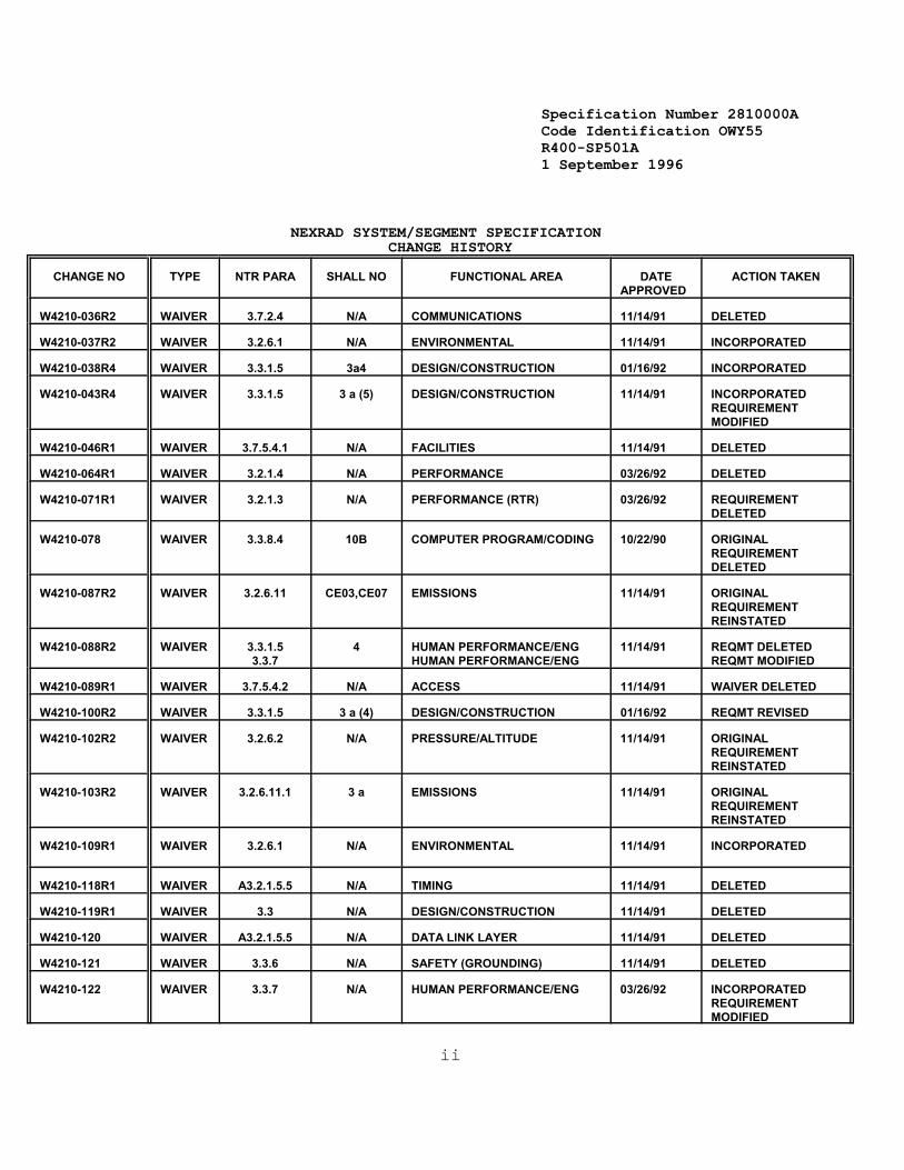
NEXRAD SYSTEM/SEGMENT SPECIFICATION CHANGE HISTORY
CHANGE NO TYPE NTR PARA SHALL NO FUNCTIONAL AREA DATEAPPROVED
ACTION TAKEN
W4210-036R2 WAIVER 3.7.2.4 N/A COMMUNICATIONS 11/14/91 DELETED
W4210-037R2 WAIVER 3.2.6.1 N/A ENVIRONMENTAL 11/14/91 INCORPORATED
W4210-038R4 WAIVER 3.3.1.5 3a4 DESIGN/CONSTRUCTION 01/16/92 INCORPORATED
W4210-043R4 WAIVER 3.3.1.5 3 a (5) DESIGN/CONSTRUCTION 11/14/91 INCORPORATEDREQUIREMENTMODIFIED
W4210-046R1 WAIVER 3.7.5.4.1 N/A FACILITIES 11/14/91 DELETED
W4210-064R1 WAIVER 3.2.1.4 N/A PERFORMANCE 03/26/92 DELETED
W4210-071R1 WAIVER 3.2.1.3 N/A PERFORMANCE (RTR) 03/26/92 REQUIREMENTDELETED
W4210-078 WAIVER 3.3.8.4 10B COMPUTER PROGRAM/CODING 10/22/90 ORIGINALREQUIREMENTDELETED
W4210-087R2 WAIVER 3.2.6.11 CE03,CE07 EMISSIONS 11/14/91 ORIGINALREQUIREMENTREINSTATED
W4210-088R2 WAIVER 3.3.1.53.3.7
4 HUMAN PERFORMANCE/ENGHUMAN PERFORMANCE/ENG
11/14/91 REQMT DELETEDREQMT MODIFIED
W4210-089R1 WAIVER 3.7.5.4.2 N/A ACCESS 11/14/91 WAIVER DELETED
W4210-100R2 WAIVER 3.3.1.5 3 a (4) DESIGN/CONSTRUCTION 01/16/92 REQMT REVISED
W4210-102R2 WAIVER 3.2.6.2 N/A PRESSURE/ALTITUDE 11/14/91 ORIGINALREQUIREMENTREINSTATED
W4210-103R2 WAIVER 3.2.6.11.1 3 a EMISSIONS 11/14/91 ORIGINALREQUIREMENTREINSTATED
W4210-109R1 WAIVER 3.2.6.1 N/A ENVIRONMENTAL 11/14/91 INCORPORATED
W4210-118R1 WAIVER A3.2.1.5.5 N/A TIMING 11/14/91 DELETED
W4210-119R1 WAIVER 3.3 N/A DESIGN/CONSTRUCTION 11/14/91 DELETED
W4210-120 WAIVER A3.2.1.5.5 N/A DATA LINK LAYER 11/14/91 DELETED
W4210-121 WAIVER 3.3.6 N/A SAFETY (GROUNDING) 11/14/91 DELETED
W4210-122 WAIVER 3.3.7 N/A HUMAN PERFORMANCE/ENG 03/26/92 INCORPORATEDREQUIREMENTMODIFIED
Specification Number 2810000ACode Identification OWY55 R400-SP501A 1 September 1996
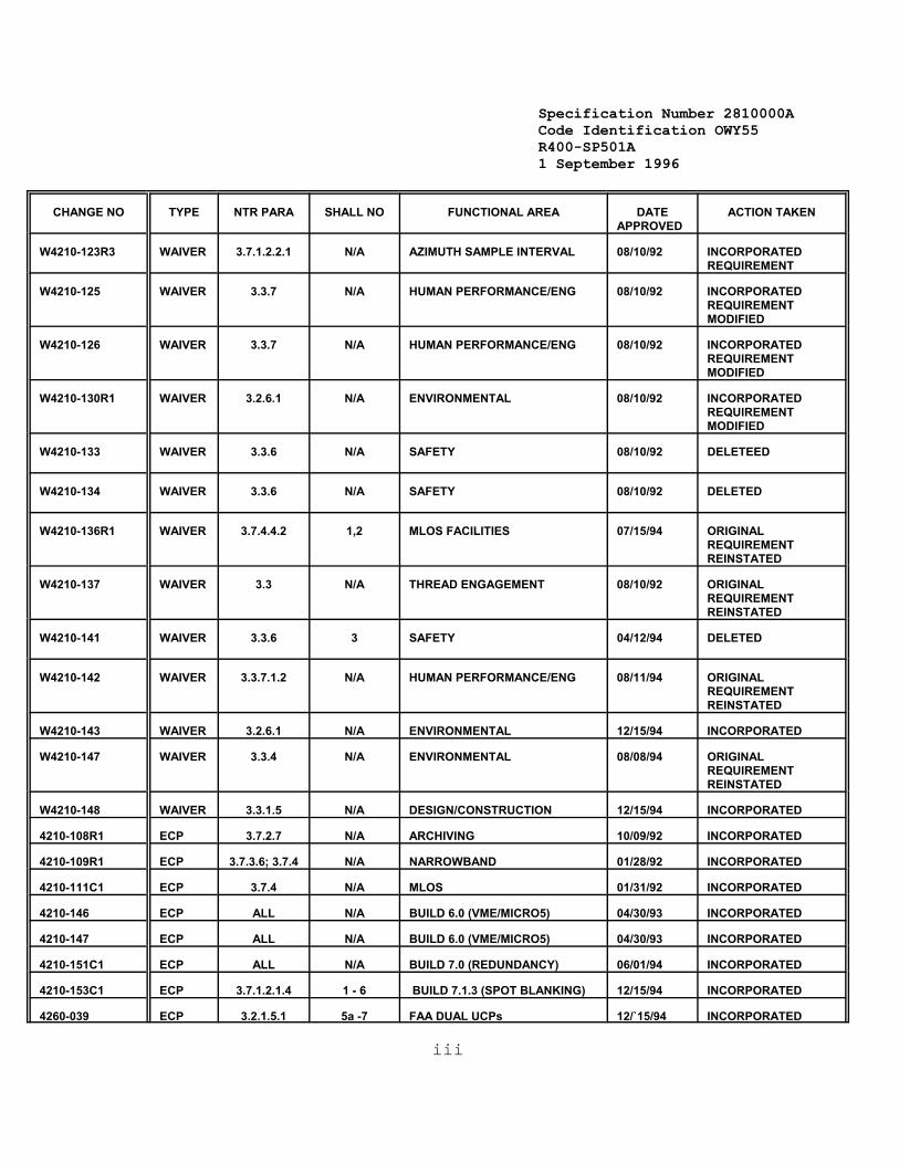
CHANGE NO TYPE NTR PARA SHALL NO FUNCTIONAL AREA DATEAPPROVED
ACTION TAKEN
iii
W4210-123R3 WAIVER 3.7.1.2.2.1 N/A AZIMUTH SAMPLE INTERVAL 08/10/92 INCORPORATEDREQUIREMENT
W4210-125 WAIVER 3.3.7 N/A HUMAN PERFORMANCE/ENG 08/10/92 INCORPORATEDREQUIREMENTMODIFIED
W4210-126 WAIVER 3.3.7 N/A HUMAN PERFORMANCE/ENG 08/10/92 INCORPORATEDREQUIREMENTMODIFIED
W4210-130R1 WAIVER 3.2.6.1 N/A ENVIRONMENTAL 08/10/92 INCORPORATEDREQUIREMENTMODIFIED
W4210-133 WAIVER 3.3.6 N/A SAFETY 08/10/92 DELETEED
W4210-134 WAIVER 3.3.6 N/A SAFETY 08/10/92 DELETED
W4210-136R1 WAIVER 3.7.4.4.2 1,2 MLOS FACILITIES 07/15/94 ORIGINALREQUIREMENTREINSTATED
W4210-137 WAIVER 3.3 N/A THREAD ENGAGEMENT 08/10/92 ORIGINALREQUIREMENTREINSTATED
W4210-141 WAIVER 3.3.6 3 SAFETY 04/12/94 DELETED
W4210-142 WAIVER 3.3.7.1.2 N/A HUMAN PERFORMANCE/ENG 08/11/94 ORIGINALREQUIREMENTREINSTATED
W4210-143 WAIVER 3.2.6.1 N/A ENVIRONMENTAL 12/15/94 INCORPORATED
W4210-147 WAIVER 3.3.4 N/A ENVIRONMENTAL 08/08/94 ORIGINALREQUIREMENTREINSTATED
W4210-148 WAIVER 3.3.1.5 N/A DESIGN/CONSTRUCTION 12/15/94 INCORPORATED
4210-108R1 ECP 3.7.2.7 N/A ARCHIVING 10/09/92 INCORPORATED
4210-109R1 ECP 3.7.3.6; 3.7.4 N/A NARROWBAND 01/28/92 INCORPORATED
4210-111C1 ECP 3.7.4 N/A MLOS 01/31/92 INCORPORATED
4210-146 ECP ALL N/A BUILD 6.0 (VME/MICRO5) 04/30/93 INCORPORATED
4210-147 ECP ALL N/A BUILD 6.0 (VME/MICRO5) 04/30/93 INCORPORATED
4210-151C1 ECP ALL N/A BUILD 7.0 (REDUNDANCY) 06/01/94 INCORPORATED
4210-153C1 ECP 3.7.1.2.1.4 1 - 6 BUILD 7.1.3 (SPOT BLANKING) 12/15/94 INCORPORATED
4260-039 ECP 3.2.1.5.1 5a -7 FAA DUAL UCPs 12/`15/94 INCORPORATED

Specification Number 2810000ACode Identification OWY55 R400-SP501A 1 September 1996
CHANGE NO TYPE NTR PARA SHALL NO FUNCTIONAL AREA DATEAPPROVED
ACTION TAKEN
iv
4260-045R1 ECP 3.7.1.4 11 REDUNDANT SYSTEM DUALFREQUENCIES
04/15/96 INCORPORATED
SPO1-016 CCP APP-C FFP ALGORITHM REPORT 02/13/93 INCORPORATED
SPO1-040 CCP 3.7.2.6 N/A RPG STATUS MONITORING 12/16/93 INCORPORATED
SPO1-045 CCP APP-E 30 NEXRAD PRODUCTS 05/26/94 INCORPORATED
SPO1-046 CCP APP-E 29 NEXRAD PRODUCTS 05/26/94 INCORPORATED
SPO1-061 CCP 3.7.3.7 N/A STATUS MONITORING 05/26/94 INCORPORATED
F0013-R00A00 ECP ALL N/A BUILD 8.0 03/31/95 INCORPORATED
F0048-R00A00 ECP ALL N/A BUILD 9.0 01/26/96 INCORPORATED

Specification Number 2810000ACode Identification OWY55 R400-SP501A 1 September 1996
v
Table of Content
1. SCOPE . . . . . . . . . . . . . . . . . . . . . . . . . . . . . . . . . . . . . . . . . . . . . . . . . . . . . . . . . . . . . . . . . . . . . . . . . . . . . . . . . . . . . . . . . . . . 1-1
2. APPLICABLE DOCUMENTS . . . . . . . . . . . . . . . . . . . . . . . . . . . . . . . . . . . . . . . . . . . . . . . . . . . . . . . . . . . . . . . . . . . . . . . . . . . 2-12.1 Government Documents . . . . . . . . . . . . . . . . . . . . . . . . . . . . . . . . . . . . . . . . . . . . . . . . . . . . . . . . . . . . . . . . . . . . . 2-12.1.1 Military Standards . . . . . . . . . . . . . . . . . . . . . . . . . . . . . . . . . . . . . . . . . . . . . . . . . . . . . . . . . . . . . . . . . . . . . . . . 2-12.1.2 Federal Documents . . . . . . . . . . . . . . . . . . . . . . . . . . . . . . . . . . . . . . . . . . . . . . . . . . . . . . . . . . . . . . . . . . . . . . . 2-22.2 Non-Government Documents . . . . . . . . . . . . . . . . . . . . . . . . . . . . . . . . . . . . . . . . . . . . . . . . . . . . . . . . . . . . . . . . . 2-22.2.1 American National Standards Institute (ANSI) Standards . . . . . . . . . . . . . . . . . . . . . . . . . . . . . . . . . . . . . . . . 2-22.2.2 Electronic Industries Association (EIA) Documents . . . . . . . . . . . . . . . . . . . . . . . . . . . . . . . . . . . . . . . . . . . . . 2-32.2.3 Other Non-Government Documents . . . . . . . . . . . . . . . . . . . . . . . . . . . . . . . . . . . . . . . . . . . . . . . . . . . . . . . . . . 2-32.3 Precedence of Documents . . . . . . . . . . . . . . . . . . . . . . . . . . . . . . . . . . . . . . . . . . . . . . . . . . . . . . . . . . . . . . . . . . . 2-3
3. REQUIREMENTS . . . . . . . . . . . . . . . . . . . . . . . . . . . . . . . . . . . . . . . . . . . . . . . . . . . . . . . . . . . . . . . . . . . . . . . . . . . . . . . . . . . . 3-13.1 System Definition . . . . . . . . . . . . . . . . . . . . . . . . . . . . . . . . . . . . . . . . . . . . . . . . . . . . . . . . . . . . . . . . . . . . . . . . . . 3-13.1.1 General Description . . . . . . . . . . . . . . . . . . . . . . . . . . . . . . . . . . . . . . . . . . . . . . . . . . . . . . . . . . . . . . . . . . . . . . . 3-13.1.1.1 System Users . . . . . . . . . . . . . . . . . . . . . . . . . . . . . . . . . . . . . . . . . . . . . . . . . . . . . . . . . . . . . . . . . . . . . . . . . . . 3-13.1.1.1.1 Principal Users . . . . . . . . . . . . . . . . . . . . . . . . . . . . . . . . . . . . . . . . . . . . . . . . . . . . . . . . . . . . . . . . . . . . . . . . 3-13.1.1.1.2 Other Users . . . . . . . . . . . . . . . . . . . . . . . . . . . . . . . . . . . . . . . . . . . . . . . . . . . . . . . . . . . . . . . . . . . . . . . . . . . 3-23.1.1.2 Product Generation . . . . . . . . . . . . . . . . . . . . . . . . . . . . . . . . . . . . . . . . . . . . . . . . . . . . . . . . . . . . . . . . . . . . . . 3-23.1.1.3 Product Distribution . . . . . . . . . . . . . . . . . . . . . . . . . . . . . . . . . . . . . . . . . . . . . . . . . . . . . . . . . . . . . . . . . . . . . 3-23.1.1.3.1 Principal User Product Distribution . . . . . . . . . . . . . . . . . . . . . . . . . . . . . . . . . . . . . . . . . . . . . . . . . . . . . . . 3-33.1.1.3.2 Other User Products . . . . . . . . . . . . . . . . . . . . . . . . . . . . . . . . . . . . . . . . . . . . . . . . . . . . . . . . . . . . . . . . . . . 3-43.1.1.4 Principal User Processing and Display . . . . . . . . . . . . . . . . . . . . . . . . . . . . . . . . . . . . . . . . . . . . . . . . . . . . . . 3-43.1.1.5 Radar Siting . . . . . . . . . . . . . . . . . . . . . . . . . . . . . . . . . . . . . . . . . . . . . . . . . . . . . . . . . . . . . . . . . . . . . . . . . . . . 3-43.1.1.6 Support Facilities . . . . . . . . . . . . . . . . . . . . . . . . . . . . . . . . . . . . . . . . . . . . . . . . . . . . . . . . . . . . . . . . . . . . . . . 3-43.1.1.6.1 Maintenance and Supply Depots . . . . . . . . . . . . . . . . . . . . . . . . . . . . . . . . . . . . . . . . . . . . . . . . . . . . . . . . . 3-53.1.1.6.2 Maintenance Training Facility . . . . . . . . . . . . . . . . . . . . . . . . . . . . . . . . . . . . . . . . . . . . . . . . . . . . . . . . . . . . 3-53.1.1.6.3 Operational Training Facility . . . . . . . . . . . . . . . . . . . . . . . . . . . . . . . . . . . . . . . . . . . . . . . . . . . . . . . . . . . . . 3-53.1.1.6.4 Operational Support Facility . . . . . . . . . . . . . . . . . . . . . . . . . . . . . . . . . . . . . . . . . . . . . . . . . . . . . . . . . . . . . 3-53.1.1.7 Functional Areas . . . . . . . . . . . . . . . . . . . . . . . . . . . . . . . . . . . . . . . . . . . . . . . . . . . . . . . . . . . . . . . . . . . . . . . . 3-63.1.1.7.1 Radar Data Acquisition . . . . . . . . . . . . . . . . . . . . . . . . . . . . . . . . . . . . . . . . . . . . . . . . . . . . . . . . . . . . . . . . . 3-83.1.1.7.2 Radar Product Generation . . . . . . . . . . . . . . . . . . . . . . . . . . . . . . . . . . . . . . . . . . . . . . . . . . . . . . . . . . . . . . . 3-83.1.1.7.3 Principal User Processing . . . . . . . . . . . . . . . . . . . . . . . . . . . . . . . . . . . . . . . . . . . . . . . . . . . . . . . . . . . . . . . 3-83.1.1.7.4 Communications . . . . . . . . . . . . . . . . . . . . . . . . . . . . . . . . . . . . . . . . . . . . . . . . . . . . . . . . . . . . . . . . . . . . . . 3-83.1.1.7.5 Facilities . . . . . . . . . . . . . . . . . . . . . . . . . . . . . . . . . . . . . . . . . . . . . . . . . . . . . . . . . . . . . . . . . . . . . . . . . . . . . 3-83.1.1.7.6 Support . . . . . . . . . . . . . . . . . . . . . . . . . . . . . . . . . . . . . . . . . . . . . . . . . . . . . . . . . . . . . . . . . . . . . . . . . . . . . . 3-93.1.2 Missions . . . . . . . . . . . . . . . . . . . . . . . . . . . . . . . . . . . . . . . . . . . . . . . . . . . . . . . . . . . . . . . . . . . . . . . . . . . . . . . . 3-93.1.2.1 Department of Commerce Missions . . . . . . . . . . . . . . . . . . . . . . . . . . . . . . . . . . . . . . . . . . . . . . . . . . . . . . . . 3-93.1.2.2 Department of Defense Missions . . . . . . . . . . . . . . . . . . . . . . . . . . . . . . . . . . . . . . . . . . . . . . . . . . . . . . . . . . . 3-93.1.2.3 Department of Transportation Missions . . . . . . . . . . . . . . . . . . . . . . . . . . . . . . . . . . . . . . . . . . . . . . . . . . . . . 3-93.1.2.4 System Mission . . . . . . . . . . . . . . . . . . . . . . . . . . . . . . . . . . . . . . . . . . . . . . . . . . . . . . . . . . . . . . . . . . . . . . . . 3-103.1.3 System Diagrams . . . . . . . . . . . . . . . . . . . . . . . . . . . . . . . . . . . . . . . . . . . . . . . . . . . . . . . . . . . . . . . . . . . . . . . . 3-103.1.4 Communications Interfaces . . . . . . . . . . . . . . . . . . . . . . . . . . . . . . . . . . . . . . . . . . . . . . . . . . . . . . . . . . . . . . . 3-103.1.5 Government Furnished Property (GFP) List . . . . . . . . . . . . . . . . . . . . . . . . . . . . . . . . . . . . . . . . . . . . . . . . . . 3-163.1.6 Operational and Organizational Concepts . . . . . . . . . . . . . . . . . . . . . . . . . . . . . . . . . . . . . . . . . . . . . . . . . . . . 3-163.2 System Characteristics . . . . . . . . . . . . . . . . . . . . . . . . . . . . . . . . . . . . . . . . . . . . . . . . . . . . . . . . . . . . . . . . . . . . . 3-163.2.1 Performance Characteristics . . . . . . . . . . . . . . . . . . . . . . . . . . . . . . . . . . . . . . . . . . . . . . . . . . . . . . . . . . . . . . 3-163.2.1.1 NEXRAD Unit Full Load . . . . . . . . . . . . . . . . . . . . . . . . . . . . . . . . . . . . . . . . . . . . . . . . . . . . . . . . . . . . . . . . . 3-163.2.1.2 Peak Request Rates . . . . . . . . . . . . . . . . . . . . . . . . . . . . . . . . . . . . . . . . . . . . . . . . . . . . . . . . . . . . . . . . . . . . 3-183.2.1.3 Response Time Requirements . . . . . . . . . . . . . . . . . . . . . . . . . . . . . . . . . . . . . . . . . . . . . . . . . . . . . . . . . . . . 3-193.2.1.3.1 Product and Background Map Display . . . . . . . . . . . . . . . . . . . . . . . . . . . . . . . . . . . . . . . . . . . . . . . . . . . . 3-213.2.1.3.2 Off-Center/Preset Center . . . . . . . . . . . . . . . . . . . . . . . . . . . . . . . . . . . . . . . . . . . . . . . . . . . . . . . . . . . . . . . 3-213.2.1.3.3 Resolution Change . . . . . . . . . . . . . . . . . . . . . . . . . . . . . . . . . . . . . . . . . . . . . . . . . . . . . . . . . . . . . . . . . . . . 3-213.2.1.3.4 Display Annotation . . . . . . . . . . . . . . . . . . . . . . . . . . . . . . . . . . . . . . . . . . . . . . . . . . . . . . . . . . . . . . . . . . . . 3-213.2.1.3.5 Display of Cursor Coordinates . . . . . . . . . . . . . . . . . . . . . . . . . . . . . . . . . . . . . . . . . . . . . . . . . . . . . . . . . . 3-223.2.1.3.6 Cursor Home . . . . . . . . . . . . . . . . . . . . . . . . . . . . . . . . . . . . . . . . . . . . . . . . . . . . . . . . . . . . . . . . . . . . . . . . . 3-223.2.1.3.7 Test Pattern Selection/Deselection . . . . . . . . . . . . . . . . . . . . . . . . . . . . . . . . . . . . . . . . . . . . . . . . . . . . . . 3-223.2.1.3.8 Status Message Output . . . . . . . . . . . . . . . . . . . . . . . . . . . . . . . . . . . . . . . . . . . . . . . . . . . . . . . . . . . . . . . . 3-22
Specification Number 2810000ACode Identification OWY55 R400-SP501A 1 September 1996
vi
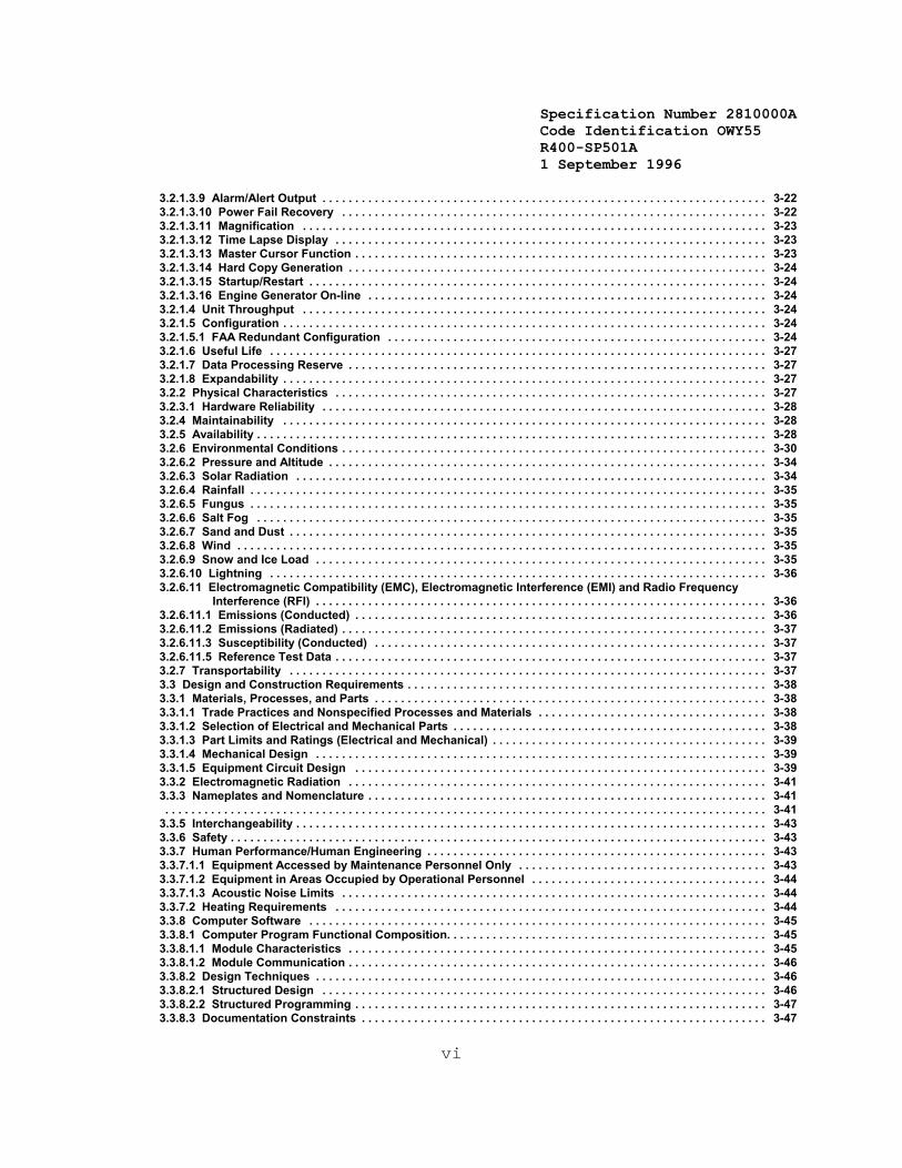
3.2.1.3.9 Alarm/Alert Output . . . . . . . . . . . . . . . . . . . . . . . . . . . . . . . . . . . . . . . . . . . . . . . . . . . . . . . . . . . . . . . . . . . . 3-223.2.1.3.10 Power Fail Recovery . . . . . . . . . . . . . . . . . . . . . . . . . . . . . . . . . . . . . . . . . . . . . . . . . . . . . . . . . . . . . . . . . 3-223.2.1.3.11 Magnification . . . . . . . . . . . . . . . . . . . . . . . . . . . . . . . . . . . . . . . . . . . . . . . . . . . . . . . . . . . . . . . . . . . . . . . 3-233.2.1.3.12 Time Lapse Display . . . . . . . . . . . . . . . . . . . . . . . . . . . . . . . . . . . . . . . . . . . . . . . . . . . . . . . . . . . . . . . . . . 3-233.2.1.3.13 Master Cursor Function . . . . . . . . . . . . . . . . . . . . . . . . . . . . . . . . . . . . . . . . . . . . . . . . . . . . . . . . . . . . . . . 3-233.2.1.3.14 Hard Copy Generation . . . . . . . . . . . . . . . . . . . . . . . . . . . . . . . . . . . . . . . . . . . . . . . . . . . . . . . . . . . . . . . . 3-243.2.1.3.15 Startup/Restart . . . . . . . . . . . . . . . . . . . . . . . . . . . . . . . . . . . . . . . . . . . . . . . . . . . . . . . . . . . . . . . . . . . . . . 3-243.2.1.3.16 Engine Generator On-line . . . . . . . . . . . . . . . . . . . . . . . . . . . . . . . . . . . . . . . . . . . . . . . . . . . . . . . . . . . . . 3-243.2.1.4 Unit Throughput . . . . . . . . . . . . . . . . . . . . . . . . . . . . . . . . . . . . . . . . . . . . . . . . . . . . . . . . . . . . . . . . . . . . . . . 3-243.2.1.5 Configuration . . . . . . . . . . . . . . . . . . . . . . . . . . . . . . . . . . . . . . . . . . . . . . . . . . . . . . . . . . . . . . . . . . . . . . . . . . 3-243.2.1.5.1 FAA Redundant Configuration . . . . . . . . . . . . . . . . . . . . . . . . . . . . . . . . . . . . . . . . . . . . . . . . . . . . . . . . . . 3-243.2.1.6 Useful Life . . . . . . . . . . . . . . . . . . . . . . . . . . . . . . . . . . . . . . . . . . . . . . . . . . . . . . . . . . . . . . . . . . . . . . . . . . . . 3-273.2.1.7 Data Processing Reserve . . . . . . . . . . . . . . . . . . . . . . . . . . . . . . . . . . . . . . . . . . . . . . . . . . . . . . . . . . . . . . . . 3-273.2.1.8 Expandability . . . . . . . . . . . . . . . . . . . . . . . . . . . . . . . . . . . . . . . . . . . . . . . . . . . . . . . . . . . . . . . . . . . . . . . . . . 3-273.2.2 Physical Characteristics . . . . . . . . . . . . . . . . . . . . . . . . . . . . . . . . . . . . . . . . . . . . . . . . . . . . . . . . . . . . . . . . . . 3-273.2.3.1 Hardware Reliability . . . . . . . . . . . . . . . . . . . . . . . . . . . . . . . . . . . . . . . . . . . . . . . . . . . . . . . . . . . . . . . . . . . . 3-283.2.4 Maintainability . . . . . . . . . . . . . . . . . . . . . . . . . . . . . . . . . . . . . . . . . . . . . . . . . . . . . . . . . . . . . . . . . . . . . . . . . . 3-283.2.5 Availability . . . . . . . . . . . . . . . . . . . . . . . . . . . . . . . . . . . . . . . . . . . . . . . . . . . . . . . . . . . . . . . . . . . . . . . . . . . . . . 3-283.2.6 Environmental Conditions . . . . . . . . . . . . . . . . . . . . . . . . . . . . . . . . . . . . . . . . . . . . . . . . . . . . . . . . . . . . . . . . . 3-303.2.6.2 Pressure and Altitude . . . . . . . . . . . . . . . . . . . . . . . . . . . . . . . . . . . . . . . . . . . . . . . . . . . . . . . . . . . . . . . . . . . 3-343.2.6.3 Solar Radiation . . . . . . . . . . . . . . . . . . . . . . . . . . . . . . . . . . . . . . . . . . . . . . . . . . . . . . . . . . . . . . . . . . . . . . . . 3-343.2.6.4 Rainfall . . . . . . . . . . . . . . . . . . . . . . . . . . . . . . . . . . . . . . . . . . . . . . . . . . . . . . . . . . . . . . . . . . . . . . . . . . . . . . . 3-353.2.6.5 Fungus . . . . . . . . . . . . . . . . . . . . . . . . . . . . . . . . . . . . . . . . . . . . . . . . . . . . . . . . . . . . . . . . . . . . . . . . . . . . . . . 3-353.2.6.6 Salt Fog . . . . . . . . . . . . . . . . . . . . . . . . . . . . . . . . . . . . . . . . . . . . . . . . . . . . . . . . . . . . . . . . . . . . . . . . . . . . . . 3-353.2.6.7 Sand and Dust . . . . . . . . . . . . . . . . . . . . . . . . . . . . . . . . . . . . . . . . . . . . . . . . . . . . . . . . . . . . . . . . . . . . . . . . . 3-353.2.6.8 Wind . . . . . . . . . . . . . . . . . . . . . . . . . . . . . . . . . . . . . . . . . . . . . . . . . . . . . . . . . . . . . . . . . . . . . . . . . . . . . . . . . 3-353.2.6.9 Snow and Ice Load . . . . . . . . . . . . . . . . . . . . . . . . . . . . . . . . . . . . . . . . . . . . . . . . . . . . . . . . . . . . . . . . . . . . . 3-353.2.6.10 Lightning . . . . . . . . . . . . . . . . . . . . . . . . . . . . . . . . . . . . . . . . . . . . . . . . . . . . . . . . . . . . . . . . . . . . . . . . . . . . 3-363.2.6.11 Electromagnetic Compatibility (EMC), Electromagnetic Interference (EMI) and Radio Frequency
Interference (RFI) . . . . . . . . . . . . . . . . . . . . . . . . . . . . . . . . . . . . . . . . . . . . . . . . . . . . . . . . . . . . . . . . . . . . . 3-363.2.6.11.1 Emissions (Conducted) . . . . . . . . . . . . . . . . . . . . . . . . . . . . . . . . . . . . . . . . . . . . . . . . . . . . . . . . . . . . . . . 3-363.2.6.11.2 Emissions (Radiated) . . . . . . . . . . . . . . . . . . . . . . . . . . . . . . . . . . . . . . . . . . . . . . . . . . . . . . . . . . . . . . . . . 3-373.2.6.11.3 Susceptibility (Conducted) . . . . . . . . . . . . . . . . . . . . . . . . . . . . . . . . . . . . . . . . . . . . . . . . . . . . . . . . . . . . 3-373.2.6.11.5 Reference Test Data . . . . . . . . . . . . . . . . . . . . . . . . . . . . . . . . . . . . . . . . . . . . . . . . . . . . . . . . . . . . . . . . . . 3-373.2.7 Transportability . . . . . . . . . . . . . . . . . . . . . . . . . . . . . . . . . . . . . . . . . . . . . . . . . . . . . . . . . . . . . . . . . . . . . . . . . 3-373.3 Design and Construction Requirements . . . . . . . . . . . . . . . . . . . . . . . . . . . . . . . . . . . . . . . . . . . . . . . . . . . . . . . 3-383.3.1 Materials, Processes, and Parts . . . . . . . . . . . . . . . . . . . . . . . . . . . . . . . . . . . . . . . . . . . . . . . . . . . . . . . . . . . . 3-383.3.1.1 Trade Practices and Nonspecified Processes and Materials . . . . . . . . . . . . . . . . . . . . . . . . . . . . . . . . . . . 3-383.3.1.2 Selection of Electrical and Mechanical Parts . . . . . . . . . . . . . . . . . . . . . . . . . . . . . . . . . . . . . . . . . . . . . . . . 3-383.3.1.3 Part Limits and Ratings (Electrical and Mechanical) . . . . . . . . . . . . . . . . . . . . . . . . . . . . . . . . . . . . . . . . . . 3-393.3.1.4 Mechanical Design . . . . . . . . . . . . . . . . . . . . . . . . . . . . . . . . . . . . . . . . . . . . . . . . . . . . . . . . . . . . . . . . . . . . . 3-393.3.1.5 Equipment Circuit Design . . . . . . . . . . . . . . . . . . . . . . . . . . . . . . . . . . . . . . . . . . . . . . . . . . . . . . . . . . . . . . . 3-393.3.2 Electromagnetic Radiation . . . . . . . . . . . . . . . . . . . . . . . . . . . . . . . . . . . . . . . . . . . . . . . . . . . . . . . . . . . . . . . . 3-413.3.3 Nameplates and Nomenclature . . . . . . . . . . . . . . . . . . . . . . . . . . . . . . . . . . . . . . . . . . . . . . . . . . . . . . . . . . . . . 3-41. . . . . . . . . . . . . . . . . . . . . . . . . . . . . . . . . . . . . . . . . . . . . . . . . . . . . . . . . . . . . . . . . . . . . . . . . . . . . . . . . . . . . . . . . . . . 3-41
3.3.5 Interchangeability . . . . . . . . . . . . . . . . . . . . . . . . . . . . . . . . . . . . . . . . . . . . . . . . . . . . . . . . . . . . . . . . . . . . . . . . 3-433.3.6 Safety . . . . . . . . . . . . . . . . . . . . . . . . . . . . . . . . . . . . . . . . . . . . . . . . . . . . . . . . . . . . . . . . . . . . . . . . . . . . . . . . . . 3-433.3.7 Human Performance/Human Engineering . . . . . . . . . . . . . . . . . . . . . . . . . . . . . . . . . . . . . . . . . . . . . . . . . . . . 3-433.3.7.1.1 Equipment Accessed by Maintenance Personnel Only . . . . . . . . . . . . . . . . . . . . . . . . . . . . . . . . . . . . . . 3-433.3.7.1.2 Equipment in Areas Occupied by Operational Personnel . . . . . . . . . . . . . . . . . . . . . . . . . . . . . . . . . . . . 3-443.3.7.1.3 Acoustic Noise Limits . . . . . . . . . . . . . . . . . . . . . . . . . . . . . . . . . . . . . . . . . . . . . . . . . . . . . . . . . . . . . . . . . 3-443.3.7.2 Heating Requirements . . . . . . . . . . . . . . . . . . . . . . . . . . . . . . . . . . . . . . . . . . . . . . . . . . . . . . . . . . . . . . . . . . 3-443.3.8 Computer Software . . . . . . . . . . . . . . . . . . . . . . . . . . . . . . . . . . . . . . . . . . . . . . . . . . . . . . . . . . . . . . . . . . . . . . 3-453.3.8.1 Computer Program Functional Composition. . . . . . . . . . . . . . . . . . . . . . . . . . . . . . . . . . . . . . . . . . . . . . . . . 3-453.3.8.1.1 Module Characteristics . . . . . . . . . . . . . . . . . . . . . . . . . . . . . . . . . . . . . . . . . . . . . . . . . . . . . . . . . . . . . . . . 3-453.3.8.1.2 Module Communication . . . . . . . . . . . . . . . . . . . . . . . . . . . . . . . . . . . . . . . . . . . . . . . . . . . . . . . . . . . . . . . . 3-463.3.8.2 Design Techniques . . . . . . . . . . . . . . . . . . . . . . . . . . . . . . . . . . . . . . . . . . . . . . . . . . . . . . . . . . . . . . . . . . . . . 3-463.3.8.2.1 Structured Design . . . . . . . . . . . . . . . . . . . . . . . . . . . . . . . . . . . . . . . . . . . . . . . . . . . . . . . . . . . . . . . . . . . . 3-463.3.8.2.2 Structured Programming . . . . . . . . . . . . . . . . . . . . . . . . . . . . . . . . . . . . . . . . . . . . . . . . . . . . . . . . . . . . . . . 3-473.3.8.3 Documentation Constraints . . . . . . . . . . . . . . . . . . . . . . . . . . . . . . . . . . . . . . . . . . . . . . . . . . . . . . . . . . . . . . 3-47
Specification Number 2810000ACode Identification OWY55 R400-SP501A 1 September 1996
vii
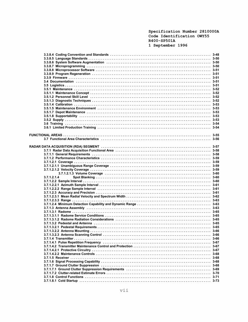
3.3.8.4 Coding Convention and Standards . . . . . . . . . . . . . . . . . . . . . . . . . . . . . . . . . . . . . . . . . . . . . . . . . . . . . . . . 3-483.3.8.5 Language Standards . . . . . . . . . . . . . . . . . . . . . . . . . . . . . . . . . . . . . . . . . . . . . . . . . . . . . . . . . . . . . . . . . . . . 3-503.3.8.6 System Software Augmentation . . . . . . . . . . . . . . . . . . . . . . . . . . . . . . . . . . . . . . . . . . . . . . . . . . . . . . . . . . 3-503.3.8.7 Microprogramming . . . . . . . . . . . . . . . . . . . . . . . . . . . . . . . . . . . . . . . . . . . . . . . . . . . . . . . . . . . . . . . . . . . . . 3-503.3.8.8 Microprocessor Software . . . . . . . . . . . . . . . . . . . . . . . . . . . . . . . . . . . . . . . . . . . . . . . . . . . . . . . . . . . . . . . . 3-513.3.8.9 Program Regeneration . . . . . . . . . . . . . . . . . . . . . . . . . . . . . . . . . . . . . . . . . . . . . . . . . . . . . . . . . . . . . . . . . . 3-513.3.9 Firmware . . . . . . . . . . . . . . . . . . . . . . . . . . . . . . . . . . . . . . . . . . . . . . . . . . . . . . . . . . . . . . . . . . . . . . . . . . . . . . . 3-513.4 Documentation . . . . . . . . . . . . . . . . . . . . . . . . . . . . . . . . . . . . . . . . . . . . . . . . . . . . . . . . . . . . . . . . . . . . . . . . . . . 3-513.5 Logistics . . . . . . . . . . . . . . . . . . . . . . . . . . . . . . . . . . . . . . . . . . . . . . . . . . . . . . . . . . . . . . . . . . . . . . . . . . . . . . . . . 3-513.5.1 Maintenance . . . . . . . . . . . . . . . . . . . . . . . . . . . . . . . . . . . . . . . . . . . . . . . . . . . . . . . . . . . . . . . . . . . . . . . . . . . . 3-523.5.1.1 Maintenance Concept . . . . . . . . . . . . . . . . . . . . . . . . . . . . . . . . . . . . . . . . . . . . . . . . . . . . . . . . . . . . . . . . . . . 3-523.5.1.2 Personnel Skill Level . . . . . . . . . . . . . . . . . . . . . . . . . . . . . . . . . . . . . . . . . . . . . . . . . . . . . . . . . . . . . . . . . . . 3-523.5.1.3 Diagnostic Techniques . . . . . . . . . . . . . . . . . . . . . . . . . . . . . . . . . . . . . . . . . . . . . . . . . . . . . . . . . . . . . . . . . . 3-523.5.1.4 Calibration . . . . . . . . . . . . . . . . . . . . . . . . . . . . . . . . . . . . . . . . . . . . . . . . . . . . . . . . . . . . . . . . . . . . . . . . . . . . 3-533.5.1.5 Maintenance Environment . . . . . . . . . . . . . . . . . . . . . . . . . . . . . . . . . . . . . . . . . . . . . . . . . . . . . . . . . . . . . . . 3-533.5.1.7 Depot Maintenance . . . . . . . . . . . . . . . . . . . . . . . . . . . . . . . . . . . . . . . . . . . . . . . . . . . . . . . . . . . . . . . . . . . . . 3-533.5.1.8 Supportability . . . . . . . . . . . . . . . . . . . . . . . . . . . . . . . . . . . . . . . . . . . . . . . . . . . . . . . . . . . . . . . . . . . . . . . . . 3-533.5.2 Supply . . . . . . . . . . . . . . . . . . . . . . . . . . . . . . . . . . . . . . . . . . . . . . . . . . . . . . . . . . . . . . . . . . . . . . . . . . . . . . . . . 3-533.6 Training . . . . . . . . . . . . . . . . . . . . . . . . . . . . . . . . . . . . . . . . . . . . . . . . . . . . . . . . . . . . . . . . . . . . . . . . . . . . . . . . . 3-543.6.1 Limited Production Training . . . . . . . . . . . . . . . . . . . . . . . . . . . . . . . . . . . . . . . . . . . . . . . . . . . . . . . . . . . . . . . 3-54
FUNCTIONAL AREAS . . . . . . . . . . . . . . . . . . . . . . . . . . . . . . . . . . . . . . . . . . . . . . . . . . . . . . . . . . . . . . . . . . . . . . . . . . . . . . . . . . 3-553.7 Functional Area Characteristics . . . . . . . . . . . . . . . . . . . . . . . . . . . . . . . . . . . . . . . . . . . . . . . . . . . . . . . . . . . . . 3-56
RADAR DATA ACQUISITION (RDA) SEGMENT . . . . . . . . . . . . . . . . . . . . . . . . . . . . . . . . . . . . . . . . . . . . . . . . . . . . . . . . . . . . . 3-573.7.1 Radar Data Acquisition Functional Area . . . . . . . . . . . . . . . . . . . . . . . . . . . . . . . . . . . . . . . . . . . . . . . . . . . . . 3-583.7.1.1 General Requirements . . . . . . . . . . . . . . . . . . . . . . . . . . . . . . . . . . . . . . . . . . . . . . . . . . . . . . . . . . . . . . . . . . 3-583.7.1.2 Performance Characteristics . . . . . . . . . . . . . . . . . . . . . . . . . . . . . . . . . . . . . . . . . . . . . . . . . . . . . . . . . . . . . 3-593.7.1.2.1 Coverage . . . . . . . . . . . . . . . . . . . . . . . . . . . . . . . . . . . . . . . . . . . . . . . . . . . . . . . . . . . . . . . . . . . . . . . . . . . . 3-593.7.1.2.1.1 Unambiguous Range Coverage . . . . . . . . . . . . . . . . . . . . . . . . . . . . . . . . . . . . . . . . . . . . . . . . . . . . . . . . 3-593.7.1.2.1.2 Velocity Coverage . . . . . . . . . . . . . . . . . . . . . . . . . . . . . . . . . . . . . . . . . . . . . . . . . . . . . . . . . . . . . . . . . . . 3-59
3.7.1.2.1.3 Volume Coverage . . . . . . . . . . . . . . . . . . . . . . . . . . . . . . . . . . . . . . . . . . . . . . . . . . . . . . . . . . . 3-603.7.1.2.1.4 Spot Blanking . . . . . . . . . . . . . . . . . . . . . . . . . . . . . . . . . . . . . . . . . . . . . . . . . . . . . . . . . . . . . . . . 3-603.7.1.2.2 Sample Interval . . . . . . . . . . . . . . . . . . . . . . . . . . . . . . . . . . . . . . . . . . . . . . . . . . . . . . . . . . . . . . . . . . . . . . . 3-603.7.1.2.2.1 Azimuth Sample Interval . . . . . . . . . . . . . . . . . . . . . . . . . . . . . . . . . . . . . . . . . . . . . . . . . . . . . . . . . . . . . . 3-613.7.1.2.2.2 Range Sample Interval . . . . . . . . . . . . . . . . . . . . . . . . . . . . . . . . . . . . . . . . . . . . . . . . . . . . . . . . . . . . . . . 3-613.7.1.2.3 Accuracy and Precision . . . . . . . . . . . . . . . . . . . . . . . . . . . . . . . . . . . . . . . . . . . . . . . . . . . . . . . . . . . . . . . . 3-613.7.1.2.3.1 Mean Radial Velocity and Spectrum Width . . . . . . . . . . . . . . . . . . . . . . . . . . . . . . . . . . . . . . . . . . . . . . . 3-623.7.1.2.3.3 Range . . . . . . . . . . . . . . . . . . . . . . . . . . . . . . . . . . . . . . . . . . . . . . . . . . . . . . . . . . . . . . . . . . . . . . . . . . . . . 3-633.7.1.2.4 Minimum Detection Capability and Dynamic Range . . . . . . . . . . . . . . . . . . . . . . . . . . . . . . . . . . . . . . . . . 3-633.7.1.3 Antenna Assembly . . . . . . . . . . . . . . . . . . . . . . . . . . . . . . . . . . . . . . . . . . . . . . . . . . . . . . . . . . . . . . . . . . . . . 3-633.7.1.3.1 Radome . . . . . . . . . . . . . . . . . . . . . . . . . . . . . . . . . . . . . . . . . . . . . . . . . . . . . . . . . . . . . . . . . . . . . . . . . . . . . 3-653.7.1.3.1.1 Radome Service Conditions . . . . . . . . . . . . . . . . . . . . . . . . . . . . . . . . . . . . . . . . . . . . . . . . . . . . . . . . . . . 3-653.7.1.3.1.2 Radome Radiation Considerations . . . . . . . . . . . . . . . . . . . . . . . . . . . . . . . . . . . . . . . . . . . . . . . . . . . . . 3-653.7.1.3.2 Pedestal and Antenna . . . . . . . . . . . . . . . . . . . . . . . . . . . . . . . . . . . . . . . . . . . . . . . . . . . . . . . . . . . . . . . . . 3-653.7.1.3.2.1 Pedestal Requirements . . . . . . . . . . . . . . . . . . . . . . . . . . . . . . . . . . . . . . . . . . . . . . . . . . . . . . . . . . . . . . . 3-653.7.1.3.2.2 Antenna Mounting . . . . . . . . . . . . . . . . . . . . . . . . . . . . . . . . . . . . . . . . . . . . . . . . . . . . . . . . . . . . . . . . . . . 3-663.7.1.3.2.3 Antenna Scanning Control . . . . . . . . . . . . . . . . . . . . . . . . . . . . . . . . . . . . . . . . . . . . . . . . . . . . . . . . . . . . 3-663.7.1.4 Transmitter . . . . . . . . . . . . . . . . . . . . . . . . . . . . . . . . . . . . . . . . . . . . . . . . . . . . . . . . . . . . . . . . . . . . . . . . . . . . 3-663.7.1.4.1 Pulse Repetition Frequency . . . . . . . . . . . . . . . . . . . . . . . . . . . . . . . . . . . . . . . . . . . . . . . . . . . . . . . . . . . . 3-673.7.1.4.2 Transmitter Maintenance Control and Protection . . . . . . . . . . . . . . . . . . . . . . . . . . . . . . . . . . . . . . . . . . . 3-673.7.1.4.2.1 Protective Circuitry . . . . . . . . . . . . . . . . . . . . . . . . . . . . . . . . . . . . . . . . . . . . . . . . . . . . . . . . . . . . . . . . . . 3-673.7.1.4.2.2 Maintenance Controls . . . . . . . . . . . . . . . . . . . . . . . . . . . . . . . . . . . . . . . . . . . . . . . . . . . . . . . . . . . . . . . . 3-683.7.1.5 Receiver . . . . . . . . . . . . . . . . . . . . . . . . . . . . . . . . . . . . . . . . . . . . . . . . . . . . . . . . . . . . . . . . . . . . . . . . . . . . . . 3-683.7.1.6 Signal Processing Capability . . . . . . . . . . . . . . . . . . . . . . . . . . . . . . . . . . . . . . . . . . . . . . . . . . . . . . . . . . . . . 3-683.7.1.7 Ground Clutter Suppression . . . . . . . . . . . . . . . . . . . . . . . . . . . . . . . . . . . . . . . . . . . . . . . . . . . . . . . . . . . . . 3-683.7.1.7.1 Ground Clutter Suppression Requirements . . . . . . . . . . . . . . . . . . . . . . . . . . . . . . . . . . . . . . . . . . . . . . . 3-693.7.1.7.2 Clutter-related Estimate Errors . . . . . . . . . . . . . . . . . . . . . . . . . . . . . . . . . . . . . . . . . . . . . . . . . . . . . . . . . . 3-703.7.1.8 Control Functions . . . . . . . . . . . . . . . . . . . . . . . . . . . . . . . . . . . . . . . . . . . . . . . . . . . . . . . . . . . . . . . . . . . . . . 3-713.7.1.8.1 Cold Startup . . . . . . . . . . . . . . . . . . . . . . . . . . . . . . . . . . . . . . . . . . . . . . . . . . . . . . . . . . . . . . . . . . . . . . . . . 3-73
Specification Number 2810000ACode Identification OWY55 R400-SP501A 1 September 1996
viii
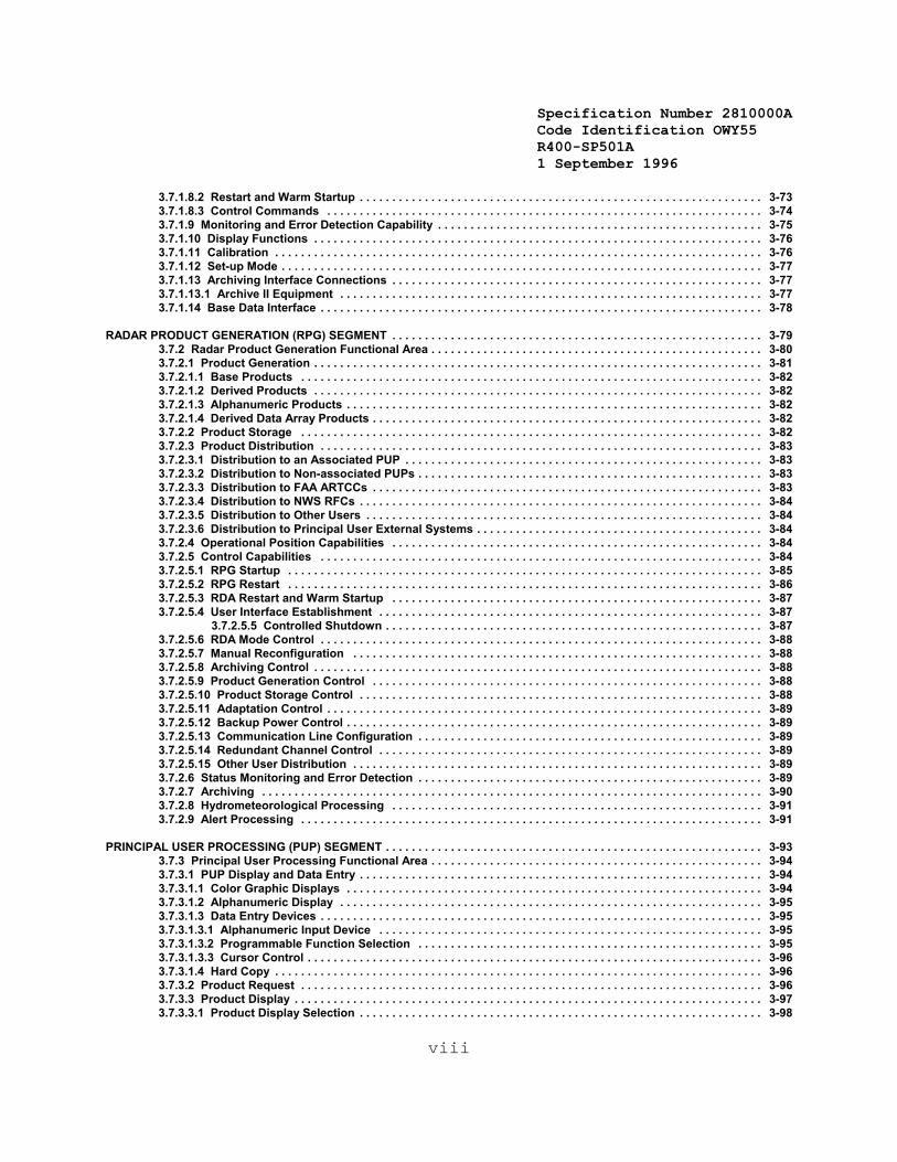
3.7.1.8.2 Restart and Warm Startup . . . . . . . . . . . . . . . . . . . . . . . . . . . . . . . . . . . . . . . . . . . . . . . . . . . . . . . . . . . . . . 3-733.7.1.8.3 Control Commands . . . . . . . . . . . . . . . . . . . . . . . . . . . . . . . . . . . . . . . . . . . . . . . . . . . . . . . . . . . . . . . . . . . 3-743.7.1.9 Monitoring and Error Detection Capability . . . . . . . . . . . . . . . . . . . . . . . . . . . . . . . . . . . . . . . . . . . . . . . . . . 3-753.7.1.10 Display Functions . . . . . . . . . . . . . . . . . . . . . . . . . . . . . . . . . . . . . . . . . . . . . . . . . . . . . . . . . . . . . . . . . . . . . 3-763.7.1.11 Calibration . . . . . . . . . . . . . . . . . . . . . . . . . . . . . . . . . . . . . . . . . . . . . . . . . . . . . . . . . . . . . . . . . . . . . . . . . . . 3-763.7.1.12 Set-up Mode . . . . . . . . . . . . . . . . . . . . . . . . . . . . . . . . . . . . . . . . . . . . . . . . . . . . . . . . . . . . . . . . . . . . . . . . . . 3-773.7.1.13 Archiving Interface Connections . . . . . . . . . . . . . . . . . . . . . . . . . . . . . . . . . . . . . . . . . . . . . . . . . . . . . . . . . 3-773.7.1.13.1 Archive II Equipment . . . . . . . . . . . . . . . . . . . . . . . . . . . . . . . . . . . . . . . . . . . . . . . . . . . . . . . . . . . . . . . . . 3-773.7.1.14 Base Data Interface . . . . . . . . . . . . . . . . . . . . . . . . . . . . . . . . . . . . . . . . . . . . . . . . . . . . . . . . . . . . . . . . . . . . 3-78
RADAR PRODUCT GENERATION (RPG) SEGMENT . . . . . . . . . . . . . . . . . . . . . . . . . . . . . . . . . . . . . . . . . . . . . . . . . . . . . . . . . 3-793.7.2 Radar Product Generation Functional Area . . . . . . . . . . . . . . . . . . . . . . . . . . . . . . . . . . . . . . . . . . . . . . . . . . . 3-803.7.2.1 Product Generation . . . . . . . . . . . . . . . . . . . . . . . . . . . . . . . . . . . . . . . . . . . . . . . . . . . . . . . . . . . . . . . . . . . . . 3-813.7.2.1.1 Base Products . . . . . . . . . . . . . . . . . . . . . . . . . . . . . . . . . . . . . . . . . . . . . . . . . . . . . . . . . . . . . . . . . . . . . . . 3-823.7.2.1.2 Derived Products . . . . . . . . . . . . . . . . . . . . . . . . . . . . . . . . . . . . . . . . . . . . . . . . . . . . . . . . . . . . . . . . . . . . . 3-823.7.2.1.3 Alphanumeric Products . . . . . . . . . . . . . . . . . . . . . . . . . . . . . . . . . . . . . . . . . . . . . . . . . . . . . . . . . . . . . . . . 3-823.7.2.1.4 Derived Data Array Products . . . . . . . . . . . . . . . . . . . . . . . . . . . . . . . . . . . . . . . . . . . . . . . . . . . . . . . . . . . . 3-823.7.2.2 Product Storage . . . . . . . . . . . . . . . . . . . . . . . . . . . . . . . . . . . . . . . . . . . . . . . . . . . . . . . . . . . . . . . . . . . . . . . 3-823.7.2.3 Product Distribution . . . . . . . . . . . . . . . . . . . . . . . . . . . . . . . . . . . . . . . . . . . . . . . . . . . . . . . . . . . . . . . . . . . . 3-833.7.2.3.1 Distribution to an Associated PUP . . . . . . . . . . . . . . . . . . . . . . . . . . . . . . . . . . . . . . . . . . . . . . . . . . . . . . . 3-833.7.2.3.2 Distribution to Non-associated PUPs . . . . . . . . . . . . . . . . . . . . . . . . . . . . . . . . . . . . . . . . . . . . . . . . . . . . . 3-833.7.2.3.3 Distribution to FAA ARTCCs . . . . . . . . . . . . . . . . . . . . . . . . . . . . . . . . . . . . . . . . . . . . . . . . . . . . . . . . . . . . 3-833.7.2.3.4 Distribution to NWS RFCs . . . . . . . . . . . . . . . . . . . . . . . . . . . . . . . . . . . . . . . . . . . . . . . . . . . . . . . . . . . . . . 3-843.7.2.3.5 Distribution to Other Users . . . . . . . . . . . . . . . . . . . . . . . . . . . . . . . . . . . . . . . . . . . . . . . . . . . . . . . . . . . . . 3-843.7.2.3.6 Distribution to Principal User External Systems . . . . . . . . . . . . . . . . . . . . . . . . . . . . . . . . . . . . . . . . . . . . 3-843.7.2.4 Operational Position Capabilities . . . . . . . . . . . . . . . . . . . . . . . . . . . . . . . . . . . . . . . . . . . . . . . . . . . . . . . . . 3-843.7.2.5 Control Capabilities . . . . . . . . . . . . . . . . . . . . . . . . . . . . . . . . . . . . . . . . . . . . . . . . . . . . . . . . . . . . . . . . . . . . 3-843.7.2.5.1 RPG Startup . . . . . . . . . . . . . . . . . . . . . . . . . . . . . . . . . . . . . . . . . . . . . . . . . . . . . . . . . . . . . . . . . . . . . . . . . 3-853.7.2.5.2 RPG Restart . . . . . . . . . . . . . . . . . . . . . . . . . . . . . . . . . . . . . . . . . . . . . . . . . . . . . . . . . . . . . . . . . . . . . . . . . 3-863.7.2.5.3 RDA Restart and Warm Startup . . . . . . . . . . . . . . . . . . . . . . . . . . . . . . . . . . . . . . . . . . . . . . . . . . . . . . . . . 3-873.7.2.5.4 User Interface Establishment . . . . . . . . . . . . . . . . . . . . . . . . . . . . . . . . . . . . . . . . . . . . . . . . . . . . . . . . . . . 3-87
3.7.2.5.5 Controlled Shutdown . . . . . . . . . . . . . . . . . . . . . . . . . . . . . . . . . . . . . . . . . . . . . . . . . . . . . . . . . . 3-873.7.2.5.6 RDA Mode Control . . . . . . . . . . . . . . . . . . . . . . . . . . . . . . . . . . . . . . . . . . . . . . . . . . . . . . . . . . . . . . . . . . . . 3-883.7.2.5.7 Manual Reconfiguration . . . . . . . . . . . . . . . . . . . . . . . . . . . . . . . . . . . . . . . . . . . . . . . . . . . . . . . . . . . . . . . 3-883.7.2.5.8 Archiving Control . . . . . . . . . . . . . . . . . . . . . . . . . . . . . . . . . . . . . . . . . . . . . . . . . . . . . . . . . . . . . . . . . . . . . 3-883.7.2.5.9 Product Generation Control . . . . . . . . . . . . . . . . . . . . . . . . . . . . . . . . . . . . . . . . . . . . . . . . . . . . . . . . . . . . 3-883.7.2.5.10 Product Storage Control . . . . . . . . . . . . . . . . . . . . . . . . . . . . . . . . . . . . . . . . . . . . . . . . . . . . . . . . . . . . . . 3-883.7.2.5.11 Adaptation Control . . . . . . . . . . . . . . . . . . . . . . . . . . . . . . . . . . . . . . . . . . . . . . . . . . . . . . . . . . . . . . . . . . . 3-893.7.2.5.12 Backup Power Control . . . . . . . . . . . . . . . . . . . . . . . . . . . . . . . . . . . . . . . . . . . . . . . . . . . . . . . . . . . . . . . . 3-893.7.2.5.13 Communication Line Configuration . . . . . . . . . . . . . . . . . . . . . . . . . . . . . . . . . . . . . . . . . . . . . . . . . . . . . 3-893.7.2.5.14 Redundant Channel Control . . . . . . . . . . . . . . . . . . . . . . . . . . . . . . . . . . . . . . . . . . . . . . . . . . . . . . . . . . . 3-893.7.2.5.15 Other User Distribution . . . . . . . . . . . . . . . . . . . . . . . . . . . . . . . . . . . . . . . . . . . . . . . . . . . . . . . . . . . . . . . 3-893.7.2.6 Status Monitoring and Error Detection . . . . . . . . . . . . . . . . . . . . . . . . . . . . . . . . . . . . . . . . . . . . . . . . . . . . . 3-893.7.2.7 Archiving . . . . . . . . . . . . . . . . . . . . . . . . . . . . . . . . . . . . . . . . . . . . . . . . . . . . . . . . . . . . . . . . . . . . . . . . . . . . . 3-903.7.2.8 Hydrometeorological Processing . . . . . . . . . . . . . . . . . . . . . . . . . . . . . . . . . . . . . . . . . . . . . . . . . . . . . . . . . 3-913.7.2.9 Alert Processing . . . . . . . . . . . . . . . . . . . . . . . . . . . . . . . . . . . . . . . . . . . . . . . . . . . . . . . . . . . . . . . . . . . . . . . 3-91
PRINCIPAL USER PROCESSING (PUP) SEGMENT . . . . . . . . . . . . . . . . . . . . . . . . . . . . . . . . . . . . . . . . . . . . . . . . . . . . . . . . . . 3-933.7.3 Principal User Processing Functional Area . . . . . . . . . . . . . . . . . . . . . . . . . . . . . . . . . . . . . . . . . . . . . . . . . . . 3-943.7.3.1 PUP Display and Data Entry . . . . . . . . . . . . . . . . . . . . . . . . . . . . . . . . . . . . . . . . . . . . . . . . . . . . . . . . . . . . . . 3-943.7.3.1.1 Color Graphic Displays . . . . . . . . . . . . . . . . . . . . . . . . . . . . . . . . . . . . . . . . . . . . . . . . . . . . . . . . . . . . . . . . 3-943.7.3.1.2 Alphanumeric Display . . . . . . . . . . . . . . . . . . . . . . . . . . . . . . . . . . . . . . . . . . . . . . . . . . . . . . . . . . . . . . . . . 3-953.7.3.1.3 Data Entry Devices . . . . . . . . . . . . . . . . . . . . . . . . . . . . . . . . . . . . . . . . . . . . . . . . . . . . . . . . . . . . . . . . . . . . 3-953.7.3.1.3.1 Alphanumeric Input Device . . . . . . . . . . . . . . . . . . . . . . . . . . . . . . . . . . . . . . . . . . . . . . . . . . . . . . . . . . . 3-953.7.3.1.3.2 Programmable Function Selection . . . . . . . . . . . . . . . . . . . . . . . . . . . . . . . . . . . . . . . . . . . . . . . . . . . . . 3-953.7.3.1.3.3 Cursor Control . . . . . . . . . . . . . . . . . . . . . . . . . . . . . . . . . . . . . . . . . . . . . . . . . . . . . . . . . . . . . . . . . . . . . . 3-963.7.3.1.4 Hard Copy . . . . . . . . . . . . . . . . . . . . . . . . . . . . . . . . . . . . . . . . . . . . . . . . . . . . . . . . . . . . . . . . . . . . . . . . . . . 3-963.7.3.2 Product Request . . . . . . . . . . . . . . . . . . . . . . . . . . . . . . . . . . . . . . . . . . . . . . . . . . . . . . . . . . . . . . . . . . . . . . . 3-963.7.3.3 Product Display . . . . . . . . . . . . . . . . . . . . . . . . . . . . . . . . . . . . . . . . . . . . . . . . . . . . . . . . . . . . . . . . . . . . . . . . 3-973.7.3.3.1 Product Display Selection . . . . . . . . . . . . . . . . . . . . . . . . . . . . . . . . . . . . . . . . . . . . . . . . . . . . . . . . . . . . . . 3-98
Specification Number 2810000ACode Identification OWY55 R400-SP501A 1 September 1996
ix
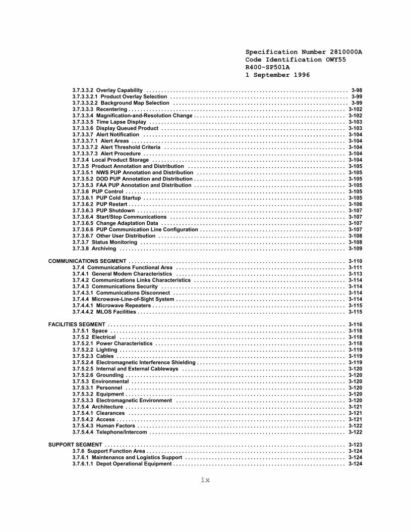
3.7.3.3.2 Overlay Capability . . . . . . . . . . . . . . . . . . . . . . . . . . . . . . . . . . . . . . . . . . . . . . . . . . . . . . . . . . . . . . . . . . . . 3-983.7.3.3.2.1 Product Overlay Selection . . . . . . . . . . . . . . . . . . . . . . . . . . . . . . . . . . . . . . . . . . . . . . . . . . . . . . . . . . . . 3-993.7.3.3.2.2 Background Map Selection . . . . . . . . . . . . . . . . . . . . . . . . . . . . . . . . . . . . . . . . . . . . . . . . . . . . . . . . . . . 3-993.7.3.3.3 Recentering . . . . . . . . . . . . . . . . . . . . . . . . . . . . . . . . . . . . . . . . . . . . . . . . . . . . . . . . . . . . . . . . . . . . . . . . . 3-1023.7.3.3.4 Magnification-and-Resolution Change . . . . . . . . . . . . . . . . . . . . . . . . . . . . . . . . . . . . . . . . . . . . . . . . . . . 3-1023.7.3.3.5 Time Lapse Display . . . . . . . . . . . . . . . . . . . . . . . . . . . . . . . . . . . . . . . . . . . . . . . . . . . . . . . . . . . . . . . . . . 3-1033.7.3.3.6 Display Queued Product . . . . . . . . . . . . . . . . . . . . . . . . . . . . . . . . . . . . . . . . . . . . . . . . . . . . . . . . . . . . . . 3-1033.7.3.3.7 Alert Notification . . . . . . . . . . . . . . . . . . . . . . . . . . . . . . . . . . . . . . . . . . . . . . . . . . . . . . . . . . . . . . . . . . . . 3-1043.7.3.3.7.1 Alert Areas . . . . . . . . . . . . . . . . . . . . . . . . . . . . . . . . . . . . . . . . . . . . . . . . . . . . . . . . . . . . . . . . . . . . . . . . 3-1043.7.3.3.7.2 Alert Threshold Criteria . . . . . . . . . . . . . . . . . . . . . . . . . . . . . . . . . . . . . . . . . . . . . . . . . . . . . . . . . . . . . 3-1043.7.3.3.7.3 Alert Procedure . . . . . . . . . . . . . . . . . . . . . . . . . . . . . . . . . . . . . . . . . . . . . . . . . . . . . . . . . . . . . . . . . . . . 3-1043.7.3.4 Local Product Storage . . . . . . . . . . . . . . . . . . . . . . . . . . . . . . . . . . . . . . . . . . . . . . . . . . . . . . . . . . . . . . . . . 3-1043.7.3.5 Product Annotation and Distribution . . . . . . . . . . . . . . . . . . . . . . . . . . . . . . . . . . . . . . . . . . . . . . . . . . . . . 3-1053.7.3.5.1 NWS PUP Annotation and Distribution . . . . . . . . . . . . . . . . . . . . . . . . . . . . . . . . . . . . . . . . . . . . . . . . . . 3-1053.7.3.5.2 DOD PUP Annotation and Distribution . . . . . . . . . . . . . . . . . . . . . . . . . . . . . . . . . . . . . . . . . . . . . . . . . . . 3-1053.7.3.5.3 FAA PUP Annotation and Distribution . . . . . . . . . . . . . . . . . . . . . . . . . . . . . . . . . . . . . . . . . . . . . . . . . . . 3-1053.7.3.6 PUP Control . . . . . . . . . . . . . . . . . . . . . . . . . . . . . . . . . . . . . . . . . . . . . . . . . . . . . . . . . . . . . . . . . . . . . . . . . . 3-1053.7.3.6.1 PUP Cold Startup . . . . . . . . . . . . . . . . . . . . . . . . . . . . . . . . . . . . . . . . . . . . . . . . . . . . . . . . . . . . . . . . . . . . 3-1053.7.3.6.2 PUP Restart . . . . . . . . . . . . . . . . . . . . . . . . . . . . . . . . . . . . . . . . . . . . . . . . . . . . . . . . . . . . . . . . . . . . . . . . . 3-1063.7.3.6.3 PUP Shutdown . . . . . . . . . . . . . . . . . . . . . . . . . . . . . . . . . . . . . . . . . . . . . . . . . . . . . . . . . . . . . . . . . . . . . . 3-1073.7.3.6.4 Start/Stop Communications . . . . . . . . . . . . . . . . . . . . . . . . . . . . . . . . . . . . . . . . . . . . . . . . . . . . . . . . . . . 3-1073.7.3.6.5 Change Adaptation Data . . . . . . . . . . . . . . . . . . . . . . . . . . . . . . . . . . . . . . . . . . . . . . . . . . . . . . . . . . . . . . 3-1073.7.3.6.6 PUP Communication Line Configuration . . . . . . . . . . . . . . . . . . . . . . . . . . . . . . . . . . . . . . . . . . . . . . . . . 3-1073.7.3.6.7 Other User Distribution . . . . . . . . . . . . . . . . . . . . . . . . . . . . . . . . . . . . . . . . . . . . . . . . . . . . . . . . . . . . . . . 3-1083.7.3.7 Status Monitoring . . . . . . . . . . . . . . . . . . . . . . . . . . . . . . . . . . . . . . . . . . . . . . . . . . . . . . . . . . . . . . . . . . . . . 3-1083.7.3.8 Archiving . . . . . . . . . . . . . . . . . . . . . . . . . . . . . . . . . . . . . . . . . . . . . . . . . . . . . . . . . . . . . . . . . . . . . . . . . . . . 3-109
COMMUNICATIONS SEGMENT . . . . . . . . . . . . . . . . . . . . . . . . . . . . . . . . . . . . . . . . . . . . . . . . . . . . . . . . . . . . . . . . . . . . . . . . . 3-1103.7.4 Communications Functional Area . . . . . . . . . . . . . . . . . . . . . . . . . . . . . . . . . . . . . . . . . . . . . . . . . . . . . . . . . 3-1113.7.4.1 General Modem Characteristics . . . . . . . . . . . . . . . . . . . . . . . . . . . . . . . . . . . . . . . . . . . . . . . . . . . . . . . . . 3-1133.7.4.2 Communications Links Characteristics . . . . . . . . . . . . . . . . . . . . . . . . . . . . . . . . . . . . . . . . . . . . . . . . . . . 3-1143.7.4.3 Communications Security . . . . . . . . . . . . . . . . . . . . . . . . . . . . . . . . . . . . . . . . . . . . . . . . . . . . . . . . . . . . . . 3-1143.7.4.3.1 Communications Disconnect . . . . . . . . . . . . . . . . . . . . . . . . . . . . . . . . . . . . . . . . . . . . . . . . . . . . . . . . . . 3-1143.7.4.4 Microwave-Line-of-Sight System . . . . . . . . . . . . . . . . . . . . . . . . . . . . . . . . . . . . . . . . . . . . . . . . . . . . . . . . . 3-1143.7.4.4.1 Microwave Repeaters . . . . . . . . . . . . . . . . . . . . . . . . . . . . . . . . . . . . . . . . . . . . . . . . . . . . . . . . . . . . . . . . . 3-1153.7.4.4.2 MLOS Facilities . . . . . . . . . . . . . . . . . . . . . . . . . . . . . . . . . . . . . . . . . . . . . . . . . . . . . . . . . . . . . . . . . . . . . . 3-115
FACILITIES SEGMENT . . . . . . . . . . . . . . . . . . . . . . . . . . . . . . . . . . . . . . . . . . . . . . . . . . . . . . . . . . . . . . . . . . . . . . . . . . . . . . . . 3-1163.7.5.1 Space . . . . . . . . . . . . . . . . . . . . . . . . . . . . . . . . . . . . . . . . . . . . . . . . . . . . . . . . . . . . . . . . . . . . . . . . . . . . . . . 3-1183.7.5.2 Electrical . . . . . . . . . . . . . . . . . . . . . . . . . . . . . . . . . . . . . . . . . . . . . . . . . . . . . . . . . . . . . . . . . . . . . . . . . . . . 3-1183.7.5.2.1 Power Characteristics . . . . . . . . . . . . . . . . . . . . . . . . . . . . . . . . . . . . . . . . . . . . . . . . . . . . . . . . . . . . . . . . 3-1183.7.5.2.2 Lighting . . . . . . . . . . . . . . . . . . . . . . . . . . . . . . . . . . . . . . . . . . . . . . . . . . . . . . . . . . . . . . . . . . . . . . . . . . . . 3-1193.7.5.2.3 Cables . . . . . . . . . . . . . . . . . . . . . . . . . . . . . . . . . . . . . . . . . . . . . . . . . . . . . . . . . . . . . . . . . . . . . . . . . . . . . 3-1193.7.5.2.4 Electromagnetic Interference Shielding . . . . . . . . . . . . . . . . . . . . . . . . . . . . . . . . . . . . . . . . . . . . . . . . . . 3-1193.7.5.2.5 Internal and External Cableways . . . . . . . . . . . . . . . . . . . . . . . . . . . . . . . . . . . . . . . . . . . . . . . . . . . . . . . 3-1203.7.5.2.6 Grounding . . . . . . . . . . . . . . . . . . . . . . . . . . . . . . . . . . . . . . . . . . . . . . . . . . . . . . . . . . . . . . . . . . . . . . . . . . 3-1203.7.5.3 Environmental . . . . . . . . . . . . . . . . . . . . . . . . . . . . . . . . . . . . . . . . . . . . . . . . . . . . . . . . . . . . . . . . . . . . . . . . 3-1203.7.5.3.1 Personnel . . . . . . . . . . . . . . . . . . . . . . . . . . . . . . . . . . . . . . . . . . . . . . . . . . . . . . . . . . . . . . . . . . . . . . . . . . 3-1203.7.5.3.2 Equipment . . . . . . . . . . . . . . . . . . . . . . . . . . . . . . . . . . . . . . . . . . . . . . . . . . . . . . . . . . . . . . . . . . . . . . . . . . 3-1203.7.5.3.3 Electromagnetic Environment . . . . . . . . . . . . . . . . . . . . . . . . . . . . . . . . . . . . . . . . . . . . . . . . . . . . . . . . . 3-1203.7.5.4 Architecture . . . . . . . . . . . . . . . . . . . . . . . . . . . . . . . . . . . . . . . . . . . . . . . . . . . . . . . . . . . . . . . . . . . . . . . . . . 3-1213.7.5.4.1 Clearances . . . . . . . . . . . . . . . . . . . . . . . . . . . . . . . . . . . . . . . . . . . . . . . . . . . . . . . . . . . . . . . . . . . . . . . . . 3-1213.7.5.4.2 Access . . . . . . . . . . . . . . . . . . . . . . . . . . . . . . . . . . . . . . . . . . . . . . . . . . . . . . . . . . . . . . . . . . . . . . . . . . . . . 3-1213.7.5.4.3 Human Factors . . . . . . . . . . . . . . . . . . . . . . . . . . . . . . . . . . . . . . . . . . . . . . . . . . . . . . . . . . . . . . . . . . . . . . 3-1223.7.5.4.4 Telephone/Intercom . . . . . . . . . . . . . . . . . . . . . . . . . . . . . . . . . . . . . . . . . . . . . . . . . . . . . . . . . . . . . . . . . . 3-122
SUPPORT SEGMENT . . . . . . . . . . . . . . . . . . . . . . . . . . . . . . . . . . . . . . . . . . . . . . . . . . . . . . . . . . . . . . . . . . . . . . . . . . . . . . . . . 3-1233.7.6 Support Function Area . . . . . . . . . . . . . . . . . . . . . . . . . . . . . . . . . . . . . . . . . . . . . . . . . . . . . . . . . . . . . . . . . . . 3-1243.7.6.1 Maintenance and Logistics Support . . . . . . . . . . . . . . . . . . . . . . . . . . . . . . . . . . . . . . . . . . . . . . . . . . . . . . 3-1243.7.6.1.1 Depot Operational Equipment . . . . . . . . . . . . . . . . . . . . . . . . . . . . . . . . . . . . . . . . . . . . . . . . . . . . . . . . . . 3-124

Specification Number 2810000ACode Identification OWY55 R400-SP501A 1 September 1996
x
3.7.6.1.2 Initial-Spares . . . . . . . . . . . . . . . . . . . . . . . . . . . . . . . . . . . . . . . . . . . . . . . . . . . . . . . . . . . . . . . . . . . . . . . . 3-1243.7.6.1.3 Maintenance Support Equipment . . . . . . . . . . . . . . . . . . . . . . . . . . . . . . . . . . . . . . . . . . . . . . . . . . . . . . . 3-1243.7.6.1.4 Off-Line Diagnostics . . . . . . . . . . . . . . . . . . . . . . . . . . . . . . . . . . . . . . . . . . . . . . . . . . . . . . . . . . . . . . . . . 3-1243.7.6.2 Training Support . . . . . . . . . . . . . . . . . . . . . . . . . . . . . . . . . . . . . . . . . . . . . . . . . . . . . . . . . . . . . . . . . . . . . . 3-1243.7.6.2.1 Maintenance Training Support . . . . . . . . . . . . . . . . . . . . . . . . . . . . . . . . . . . . . . . . . . . . . . . . . . . . . . . . . 3-1243.7.6.2.2 Operational Training Support . . . . . . . . . . . . . . . . . . . . . . . . . . . . . . . . . . . . . . . . . . . . . . . . . . . . . . . . . . 3-1253.7.6.2.2.1 Operational Equipment . . . . . . . . . . . . . . . . . . . . . . . . . . . . . . . . . . . . . . . . . . . . . . . . . . . . . . . . . . . . . . 3-1253.7.6.2.2.2 Training Support Equipment . . . . . . . . . . . . . . . . . . . . . . . . . . . . . . . . . . . . . . . . . . . . . . . . . . . . . . . . . 3-1253.7.6.2.2.3 Operational Training Software . . . . . . . . . . . . . . . . . . . . . . . . . . . . . . . . . . . . . . . . . . . . . . . . . . . . . . . . 3-1253.7.6.3 Development and Test Support . . . . . . . . . . . . . . . . . . . . . . . . . . . . . . . . . . . . . . . . . . . . . . . . . . . . . . . . . . 3-1253.7.6.4 Support Software . . . . . . . . . . . . . . . . . . . . . . . . . . . . . . . . . . . . . . . . . . . . . . . . . . . . . . . . . . . . . . . . . . . . . 3-1253.7.6.4.1 Adaptation Data Generation . . . . . . . . . . . . . . . . . . . . . . . . . . . . . . . . . . . . . . . . . . . . . . . . . . . . . . . . . . . 3-1263.7.6.4.2 Data Maintenance . . . . . . . . . . . . . . . . . . . . . . . . . . . . . . . . . . . . . . . . . . . . . . . . . . . . . . . . . . . . . . . . . . . . 3-1263.7.6.4.2.1 Adaptation Data Maintenance . . . . . . . . . . . . . . . . . . . . . . . . . . . . . . . . . . . . . . . . . . . . . . . . . . . . . . . . 3-1263.7.6.4.2.2 Geographic Data Maintenance . . . . . . . . . . . . . . . . . . . . . . . . . . . . . . . . . . . . . . . . . . . . . . . . . . . . . . . . 3-1273.7.6.4.2.3 Special Symbol Maintenance . . . . . . . . . . . . . . . . . . . . . . . . . . . . . . . . . . . . . . . . . . . . . . . . . . . . . . . . . 3-1273.7.6.4.3 Software Development and Production . . . . . . . . . . . . . . . . . . . . . . . . . . . . . . . . . . . . . . . . . . . . . . . . . . 3-1273.7.6.4.4 System Generation . . . . . . . . . . . . . . . . . . . . . . . . . . . . . . . . . . . . . . . . . . . . . . . . . . . . . . . . . . . . . . . . . . . 3-1293.7.6.4.5 Software Maintenance . . . . . . . . . . . . . . . . . . . . . . . . . . . . . . . . . . . . . . . . . . . . . . . . . . . . . . . . . . . . . . . . 3-1303.7.6.4.6 Computer Performance Monitoring . . . . . . . . . . . . . . . . . . . . . . . . . . . . . . . . . . . . . . . . . . . . . . . . . . . . . 3-1303.7.6.4.7 OJT Training Support . . . . . . . . . . . . . . . . . . . . . . . . . . . . . . . . . . . . . . . . . . . . . . . . . . . . . . . . . . . . . . . . 3-1303.7.6.4.8 Test Data Generation . . . . . . . . . . . . . . . . . . . . . . . . . . . . . . . . . . . . . . . . . . . . . . . . . . . . . . . . . . . . . . . . . 3-1313.7.6.4.9 Test Software . . . . . . . . . . . . . . . . . . . . . . . . . . . . . . . . . . . . . . . . . . . . . . . . . . . . . . . . . . . . . . . . . . . . . . . 3-1313.7.6.4.10 Program Support Library (PSL) . . . . . . . . . . . . . . . . . . . . . . . . . . . . . . . . . . . . . . . . . . . . . . . . . . . . . . . 3-131
4. QUALITY ASSURANCE . . . . . . . . . . . . . . . . . . . . . . . . . . . . . . . . . . . . . . . . . . . . . . . . . . . . . . . . . . . . . . . . . . . . . . . . . . . . . . . 4-14.1. Scope of Test and Evaluation . . . . . . . . . . . . . . . . . . . . . . . . . . . . . . . . . . . . . . . . . . . . . . . . . . . . . . . . . . . . . . . . 4-14.1.1 Test Phases . . . . . . . . . . . . . . . . . . . . . . . . . . . . . . . . . . . . . . . . . . . . . . . . . . . . . . . . . . . . . . . . . . . . . . . . . . . . . 4-14.1.2 General Test Requirements . . . . . . . . . . . . . . . . . . . . . . . . . . . . . . . . . . . . . . . . . . . . . . . . . . . . . . . . . . . . . . . . . 4-14.1.3 Documentation Requirements . . . . . . . . . . . . . . . . . . . . . . . . . . . . . . . . . . . . . . . . . . . . . . . . . . . . . . . . . . . . . . 4-24.1.3.1 Test Plans . . . . . . . . . . . . . . . . . . . . . . . . . . . . . . . . . . . . . . . . . . . . . . . . . . . . . . . . . . . . . . . . . . . . . . . . . . . . . 4-34.1.3.2 Test Procedures . . . . . . . . . . . . . . . . . . . . . . . . . . . . . . . . . . . . . . . . . . . . . . . . . . . . . . . . . . . . . . . . . . . . . . . . 4-34.1.3.3 Test Data Sheets . . . . . . . . . . . . . . . . . . . . . . . . . . . . . . . . . . . . . . . . . . . . . . . . . . . . . . . . . . . . . . . . . . . . . . . . 4-34.1.4 Test Results . . . . . . . . . . . . . . . . . . . . . . . . . . . . . . . . . . . . . . . . . . . . . . . . . . . . . . . . . . . . . . . . . . . . . . . . . . . . . 4-34.1.4.1 Test Logs . . . . . . . . . . . . . . . . . . . . . . . . . . . . . . . . . . . . . . . . . . . . . . . . . . . . . . . . . . . . . . . . . . . . . . . . . . . . . . 4-34.1.4.2 Test Reports . . . . . . . . . . . . . . . . . . . . . . . . . . . . . . . . . . . . . . . . . . . . . . . . . . . . . . . . . . . . . . . . . . . . . . . . . . . 4-34.1.4.3 Other Test Documentation . . . . . . . . . . . . . . . . . . . . . . . . . . . . . . . . . . . . . . . . . . . . . . . . . . . . . . . . . . . . . . . . 4-44.2 Validation Phase T&E . . . . . . . . . . . . . . . . . . . . . . . . . . . . . . . . . . . . . . . . . . . . . . . . . . . . . . . . . . . . . . . . . . . . . . . 4-44.2.1 Risk Reduction Verification . . . . . . . . . . . . . . . . . . . . . . . . . . . . . . . . . . . . . . . . . . . . . . . . . . . . . . . . . . . . . . . . . 4-44.2.2 Configuration Item Reliability Predictions . . . . . . . . . . . . . . . . . . . . . . . . . . . . . . . . . . . . . . . . . . . . . . . . . . . . . 4-44.2.3 Configuration Item Performance Tests . . . . . . . . . . . . . . . . . . . . . . . . . . . . . . . . . . . . . . . . . . . . . . . . . . . . . . . 4-54.2.4 Computer Program Configuration Item Tests . . . . . . . . . . . . . . . . . . . . . . . . . . . . . . . . . . . . . . . . . . . . . . . . . . 4-54.2.5 Functional Tests . . . . . . . . . . . . . . . . . . . . . . . . . . . . . . . . . . . . . . . . . . . . . . . . . . . . . . . . . . . . . . . . . . . . . . . . . . 4-54.2.5.1 Reliability Tests . . . . . . . . . . . . . . . . . . . . . . . . . . . . . . . . . . . . . . . . . . . . . . . . . . . . . . . . . . . . . . . . . . . . . . . . . 4-64.2.5.2 Performance Tests . . . . . . . . . . . . . . . . . . . . . . . . . . . . . . . . . . . . . . . . . . . . . . . . . . . . . . . . . . . . . . . . . . . . . . 4-64.2.5.2.1 RDA Performance Tests . . . . . . . . . . . . . . . . . . . . . . . . . . . . . . . . . . . . . . . . . . . . . . . . . . . . . . . . . . . . . . . . 4-64.2.5.2.2 RPG Performance Tests . . . . . . . . . . . . . . . . . . . . . . . . . . . . . . . . . . . . . . . . . . . . . . . . . . . . . . . . . . . . . . . . 4-64.2.5.2.3 PUP Performance Tests . . . . . . . . . . . . . . . . . . . . . . . . . . . . . . . . . . . . . . . . . . . . . . . . . . . . . . . . . . . . . . . . . 4-64.2.5.3 Environmental Tests . . . . . . . . . . . . . . . . . . . . . . . . . . . . . . . . . . . . . . . . . . . . . . . . . . . . . . . . . . . . . . . . . . . . . 4-74.2.5.4 Human Engineering Tests . . . . . . . . . . . . . . . . . . . . . . . . . . . . . . . . . . . . . . . . . . . . . . . . . . . . . . . . . . . . . . . . 4-74.2.6 System Tests . . . . . . . . . . . . . . . . . . . . . . . . . . . . . . . . . . . . . . . . . . . . . . . . . . . . . . . . . . . . . . . . . . . . . . . . . . . . 4-74.2.6.1 Functional Area Interface Tests . . . . . . . . . . . . . . . . . . . . . . . . . . . . . . . . . . . . . . . . . . . . . . . . . . . . . . . . . . . . 4-74.2.6.2 Communications Functional Area Tests . . . . . . . . . . . . . . . . . . . . . . . . . . . . . . . . . . . . . . . . . . . . . . . . . . . . . 4-74.2.6.3 System Performance Tests . . . . . . . . . . . . . . . . . . . . . . . . . . . . . . . . . . . . . . . . . . . . . . . . . . . . . . . . . . . . . . . 4-74.2.6.4 Maintainability Test and Evaluation . . . . . . . . . . . . . . . . . . . . . . . . . . . . . . . . . . . . . . . . . . . . . . . . . . . . . . . . . 4-74.2.6.4.1 Maintainability Prediction . . . . . . . . . . . . . . . . . . . . . . . . . . . . . . . . . . . . . . . . . . . . . . . . . . . . . . . . . . . . . . . 4-74.2.6.4.2 Maintainability Testing . . . . . . . . . . . . . . . . . . . . . . . . . . . . . . . . . . . . . . . . . . . . . . . . . . . . . . . . . . . . . . . . . . 4-84.3 Limited Production T&E . . . . . . . . . . . . . . . . . . . . . . . . . . . . . . . . . . . . . . . . . . . . . . . . . . . . . . . . . . . . . . . . . . . . . 4-84.3.1 Limited Production Configuration Item and Computer Program Configuration Item Tests . . . . . . . . . . . . . 4-9
4.3.1.1 Maximum Unexpanded Full Configuration Test . . . . . . . . . . . . . . . . . . . . . . . . . . . . . . . . . . . . . . . 4-9
Specification Number 2810000ACode Identification OWY55 R400-SP501A 1 September 1996
xi
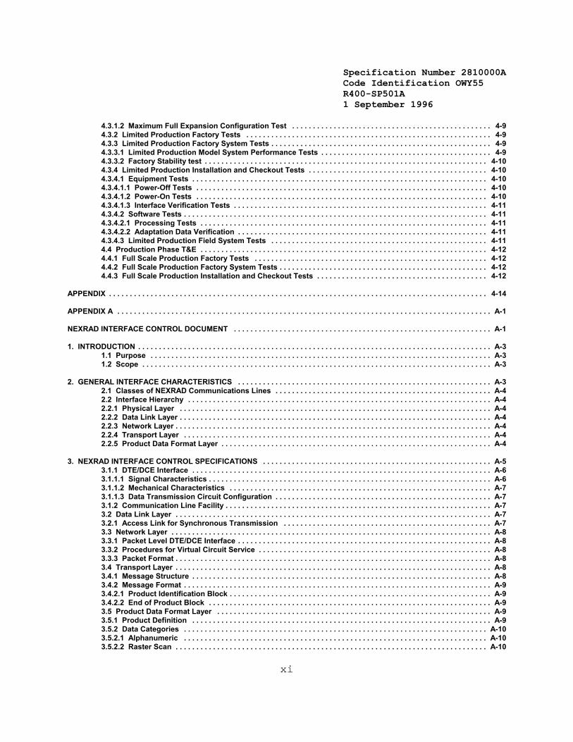
4.3.1.2 Maximum Full Expansion Configuration Test . . . . . . . . . . . . . . . . . . . . . . . . . . . . . . . . . . . . . . . . . . . . . . . . 4-94.3.2 Limited Production Factory Tests . . . . . . . . . . . . . . . . . . . . . . . . . . . . . . . . . . . . . . . . . . . . . . . . . . . . . . . . . . . 4-94.3.3 Limited Production Factory System Tests . . . . . . . . . . . . . . . . . . . . . . . . . . . . . . . . . . . . . . . . . . . . . . . . . . . . . 4-94.3.3.1 Limited Production Model System Performance Tests . . . . . . . . . . . . . . . . . . . . . . . . . . . . . . . . . . . . . . . . . 4-94.3.3.2 Factory Stability test . . . . . . . . . . . . . . . . . . . . . . . . . . . . . . . . . . . . . . . . . . . . . . . . . . . . . . . . . . . . . . . . . . . . 4-104.3.4 Limited Production Installation and Checkout Tests . . . . . . . . . . . . . . . . . . . . . . . . . . . . . . . . . . . . . . . . . . . 4-104.3.4.1 Equipment Tests . . . . . . . . . . . . . . . . . . . . . . . . . . . . . . . . . . . . . . . . . . . . . . . . . . . . . . . . . . . . . . . . . . . . . . . 4-104.3.4.1.1 Power-Off Tests . . . . . . . . . . . . . . . . . . . . . . . . . . . . . . . . . . . . . . . . . . . . . . . . . . . . . . . . . . . . . . . . . . . . . . 4-104.3.4.1.2 Power-On Tests . . . . . . . . . . . . . . . . . . . . . . . . . . . . . . . . . . . . . . . . . . . . . . . . . . . . . . . . . . . . . . . . . . . . . . 4-104.3.4.1.3 Interface Verification Tests . . . . . . . . . . . . . . . . . . . . . . . . . . . . . . . . . . . . . . . . . . . . . . . . . . . . . . . . . . . . . 4-114.3.4.2 Software Tests . . . . . . . . . . . . . . . . . . . . . . . . . . . . . . . . . . . . . . . . . . . . . . . . . . . . . . . . . . . . . . . . . . . . . . . . . 4-114.3.4.2.1 Processing Tests . . . . . . . . . . . . . . . . . . . . . . . . . . . . . . . . . . . . . . . . . . . . . . . . . . . . . . . . . . . . . . . . . . . . . 4-114.3.4.2.2 Adaptation Data Verification . . . . . . . . . . . . . . . . . . . . . . . . . . . . . . . . . . . . . . . . . . . . . . . . . . . . . . . . . . . . 4-114.3.4.3 Limited Production Field System Tests . . . . . . . . . . . . . . . . . . . . . . . . . . . . . . . . . . . . . . . . . . . . . . . . . . . . 4-114.4 Production Phase T&E . . . . . . . . . . . . . . . . . . . . . . . . . . . . . . . . . . . . . . . . . . . . . . . . . . . . . . . . . . . . . . . . . . . . . 4-124.4.1 Full Scale Production Factory Tests . . . . . . . . . . . . . . . . . . . . . . . . . . . . . . . . . . . . . . . . . . . . . . . . . . . . . . . . 4-124.4.2 Full Scale Production Factory System Tests . . . . . . . . . . . . . . . . . . . . . . . . . . . . . . . . . . . . . . . . . . . . . . . . . . 4-124.4.3 Full Scale Production Installation and Checkout Tests . . . . . . . . . . . . . . . . . . . . . . . . . . . . . . . . . . . . . . . . . 4-12
APPENDIX . . . . . . . . . . . . . . . . . . . . . . . . . . . . . . . . . . . . . . . . . . . . . . . . . . . . . . . . . . . . . . . . . . . . . . . . . . . . . . . . . . . . . . . . . . . 4-14
APPENDIX A . . . . . . . . . . . . . . . . . . . . . . . . . . . . . . . . . . . . . . . . . . . . . . . . . . . . . . . . . . . . . . . . . . . . . . . . . . . . . . . . . . . . . . . . . . A-1
NEXRAD INTERFACE CONTROL DOCUMENT . . . . . . . . . . . . . . . . . . . . . . . . . . . . . . . . . . . . . . . . . . . . . . . . . . . . . . . . . . . . . . A-1
1. INTRODUCTION . . . . . . . . . . . . . . . . . . . . . . . . . . . . . . . . . . . . . . . . . . . . . . . . . . . . . . . . . . . . . . . . . . . . . . . . . . . . . . . . . . . . . A-31.1 Purpose . . . . . . . . . . . . . . . . . . . . . . . . . . . . . . . . . . . . . . . . . . . . . . . . . . . . . . . . . . . . . . . . . . . . . . . . . . . . . . . . . . A-31.2 Scope . . . . . . . . . . . . . . . . . . . . . . . . . . . . . . . . . . . . . . . . . . . . . . . . . . . . . . . . . . . . . . . . . . . . . . . . . . . . . . . . . . . . A-3
2. GENERAL INTERFACE CHARACTERISTICS . . . . . . . . . . . . . . . . . . . . . . . . . . . . . . . . . . . . . . . . . . . . . . . . . . . . . . . . . . . . . A-32.1 Classes of NEXRAD Communications Lines . . . . . . . . . . . . . . . . . . . . . . . . . . . . . . . . . . . . . . . . . . . . . . . . . . . . A-42.2 Interface Hierarchy . . . . . . . . . . . . . . . . . . . . . . . . . . . . . . . . . . . . . . . . . . . . . . . . . . . . . . . . . . . . . . . . . . . . . . . . . A-42.2.1 Physical Layer . . . . . . . . . . . . . . . . . . . . . . . . . . . . . . . . . . . . . . . . . . . . . . . . . . . . . . . . . . . . . . . . . . . . . . . . . . . A-42.2.2 Data Link Layer . . . . . . . . . . . . . . . . . . . . . . . . . . . . . . . . . . . . . . . . . . . . . . . . . . . . . . . . . . . . . . . . . . . . . . . . . . . A-42.2.3 Network Layer . . . . . . . . . . . . . . . . . . . . . . . . . . . . . . . . . . . . . . . . . . . . . . . . . . . . . . . . . . . . . . . . . . . . . . . . . . . . A-42.2.4 Transport Layer . . . . . . . . . . . . . . . . . . . . . . . . . . . . . . . . . . . . . . . . . . . . . . . . . . . . . . . . . . . . . . . . . . . . . . . . . . A-42.2.5 Product Data Format Layer . . . . . . . . . . . . . . . . . . . . . . . . . . . . . . . . . . . . . . . . . . . . . . . . . . . . . . . . . . . . . . . . . A-4
3. NEXRAD INTERFACE CONTROL SPECIFICATIONS . . . . . . . . . . . . . . . . . . . . . . . . . . . . . . . . . . . . . . . . . . . . . . . . . . . . . . . A-53.1.1 DTE/DCE Interface . . . . . . . . . . . . . . . . . . . . . . . . . . . . . . . . . . . . . . . . . . . . . . . . . . . . . . . . . . . . . . . . . . . . . . . . A-63.1.1.1 Signal Characteristics . . . . . . . . . . . . . . . . . . . . . . . . . . . . . . . . . . . . . . . . . . . . . . . . . . . . . . . . . . . . . . . . . . . . A-63.1.1.2 Mechanical Characteristics . . . . . . . . . . . . . . . . . . . . . . . . . . . . . . . . . . . . . . . . . . . . . . . . . . . . . . . . . . . . . . . A-73.1.1.3 Data Transmission Circuit Configuration . . . . . . . . . . . . . . . . . . . . . . . . . . . . . . . . . . . . . . . . . . . . . . . . . . . . A-73.1.2 Communication Line Facility . . . . . . . . . . . . . . . . . . . . . . . . . . . . . . . . . . . . . . . . . . . . . . . . . . . . . . . . . . . . . . . . A-73.2 Data Link Layer . . . . . . . . . . . . . . . . . . . . . . . . . . . . . . . . . . . . . . . . . . . . . . . . . . . . . . . . . . . . . . . . . . . . . . . . . . . . A-73.2.1 Access Link for Synchronous Transmission . . . . . . . . . . . . . . . . . . . . . . . . . . . . . . . . . . . . . . . . . . . . . . . . . . A-73.3 Network Layer . . . . . . . . . . . . . . . . . . . . . . . . . . . . . . . . . . . . . . . . . . . . . . . . . . . . . . . . . . . . . . . . . . . . . . . . . . . . . A-83.3.1 Packet Level DTE/DCE Interface . . . . . . . . . . . . . . . . . . . . . . . . . . . . . . . . . . . . . . . . . . . . . . . . . . . . . . . . . . . . . A-83.3.2 Procedures for Virtual Circuit Service . . . . . . . . . . . . . . . . . . . . . . . . . . . . . . . . . . . . . . . . . . . . . . . . . . . . . . . . A-83.3.3 Packet Format . . . . . . . . . . . . . . . . . . . . . . . . . . . . . . . . . . . . . . . . . . . . . . . . . . . . . . . . . . . . . . . . . . . . . . . . . . . . A-83.4 Transport Layer . . . . . . . . . . . . . . . . . . . . . . . . . . . . . . . . . . . . . . . . . . . . . . . . . . . . . . . . . . . . . . . . . . . . . . . . . . . . A-83.4.1 Message Structure . . . . . . . . . . . . . . . . . . . . . . . . . . . . . . . . . . . . . . . . . . . . . . . . . . . . . . . . . . . . . . . . . . . . . . . . A-83.4.2 Message Format . . . . . . . . . . . . . . . . . . . . . . . . . . . . . . . . . . . . . . . . . . . . . . . . . . . . . . . . . . . . . . . . . . . . . . . . . . A-93.4.2.1 Product Identification Block . . . . . . . . . . . . . . . . . . . . . . . . . . . . . . . . . . . . . . . . . . . . . . . . . . . . . . . . . . . . . . . A-93.4.2.2 End of Product Block . . . . . . . . . . . . . . . . . . . . . . . . . . . . . . . . . . . . . . . . . . . . . . . . . . . . . . . . . . . . . . . . . . . . A-93.5 Product Data Format Layer . . . . . . . . . . . . . . . . . . . . . . . . . . . . . . . . . . . . . . . . . . . . . . . . . . . . . . . . . . . . . . . . . . A-93.5.1 Product Definition . . . . . . . . . . . . . . . . . . . . . . . . . . . . . . . . . . . . . . . . . . . . . . . . . . . . . . . . . . . . . . . . . . . . . . . . A-93.5.2 Data Categories . . . . . . . . . . . . . . . . . . . . . . . . . . . . . . . . . . . . . . . . . . . . . . . . . . . . . . . . . . . . . . . . . . . . . . . . . A-103.5.2.1 Alphanumeric . . . . . . . . . . . . . . . . . . . . . . . . . . . . . . . . . . . . . . . . . . . . . . . . . . . . . . . . . . . . . . . . . . . . . . . . . A-103.5.2.2 Raster Scan . . . . . . . . . . . . . . . . . . . . . . . . . . . . . . . . . . . . . . . . . . . . . . . . . . . . . . . . . . . . . . . . . . . . . . . . . . . A-10

Specification Number 2810000ACode Identification OWY55 R400-SP501A 1 September 1996
xii
3.5.2.3 Vector Graphic . . . . . . . . . . . . . . . . . . . . . . . . . . . . . . . . . . . . . . . . . . . . . . . . . . . . . . . . . . . . . . . . . . . . . . . . . A-103.5.2.4 Gridded Data . . . . . . . . . . . . . . . . . . . . . . . . . . . . . . . . . . . . . . . . . . . . . . . . . . . . . . . . . . . . . . . . . . . . . . . . . . A-10
4. REFERENCED DOCUMENTS . . . . . . . . . . . . . . . . . . . . . . . . . . . . . . . . . . . . . . . . . . . . . . . . . . . . . . . . . . . . . . . . . . . . . . . . . A-114.1 Federal . . . . . . . . . . . . . . . . . . . . . . . . . . . . . . . . . . . . . . . . . . . . . . . . . . . . . . . . . . . . . . . . . . . . . . . . . . . . . . . . . . A-114.2 National Communication Systems (NCS) . . . . . . . . . . . . . . . . . . . . . . . . . . . . . . . . . . . . . . . . . . . . . . . . . . . . . . A-114.3 American National Standards Institute (ANSI) . . . . . . . . . . . . . . . . . . . . . . . . . . . . . . . . . . . . . . . . . . . . . . . . . . A-114.4 Electronic Industries Association (EIA) . . . . . . . . . . . . . . . . . . . . . . . . . . . . . . . . . . . . . . . . . . . . . . . . . . . . . . . A-124.5 Consultative Committee for International Telegraph and Telephone . . . . . . . . . . . . . . . . . . . . . . . . . . . . . . . A-124.6 Federal Coordinator . . . . . . . . . . . . . . . . . . . . . . . . . . . . . . . . . . . . . . . . . . . . . . . . . . . . . . . . . . . . . . . . . . . . . . . A-12
5. GLOSSARY . . . . . . . . . . . . . . . . . . . . . . . . . . . . . . . . . . . . . . . . . . . . . . . . . . . . . . . . . . . . . . . . . . . . . . . . . . . . . . . . . . . . . . . A-13
APPENDIX B . . . . . . . . . . . . . . . . . . . . . . . . . . . . . . . . . . . . . . . . . . . . . . . . . . . . . . . . . . . . . . . . . . . . . . . . . . . . . . . . . . . . . . . . . . B-1
1. Definition Of Terms . . . . . . . . . . . . . . . . . . . . . . . . . . . . . . . . . . . . . . . . . . . . . . . . . . . . . . . . . . . . . . . . . . . . . . . . . . . . . . . . . . B-11.1 Adaptation Data . . . . . . . . . . . . . . . . . . . . . . . . . . . . . . . . . . . . . . . . . . . . . . . . . . . . . . . . . . . . . . . . . . . . . . . . . . . . B-11.2 Alarm . . . . . . . . . . . . . . . . . . . . . . . . . . . . . . . . . . . . . . . . . . . . . . . . . . . . . . . . . . . . . . . . . . . . . . . . . . . . . . . . . . . . B-11.3 Alert . . . . . . . . . . . . . . . . . . . . . . . . . . . . . . . . . . . . . . . . . . . . . . . . . . . . . . . . . . . . . . . . . . . . . . . . . . . . . . . . . . . . . B-11.4 Alphanumeric Products . . . . . . . . . . . . . . . . . . . . . . . . . . . . . . . . . . . . . . . . . . . . . . . . . . . . . . . . . . . . . . . . . . . . . B-11.5 Associated PUP and RPG . . . . . . . . . . . . . . . . . . . . . . . . . . . . . . . . . . . . . . . . . . . . . . . . . . . . . . . . . . . . . . . . . . . . B-11.6 Availability (Achieved) - A(a) . . . . . . . . . . . . . . . . . . . . . . . . . . . . . . . . . . . . . . . . . . . . . . . . . . . . . . . . . . . . . . . . . B-11.7 Availability (Inherent) - A(i) . . . . . . . . . . . . . . . . . . . . . . . . . . . . . . . . . . . . . . . . . . . . . . . . . . . . . . . . . . . . . . . . . . . B-21.8 Base Data . . . . . . . . . . . . . . . . . . . . . . . . . . . . . . . . . . . . . . . . . . . . . . . . . . . . . . . . . . . . . . . . . . . . . . . . . . . . . . . . . B-21.9 Base Products . . . . . . . . . . . . . . . . . . . . . . . . . . . . . . . . . . . . . . . . . . . . . . . . . . . . . . . . . . . . . . . . . . . . . . . . . . . . . B-21.10 Catastrophic Failure . . . . . . . . . . . . . . . . . . . . . . . . . . . . . . . . . . . . . . . . . . . . . . . . . . . . . . . . . . . . . . . . . . . . . . . B-21.11 Channel, Dual . . . . . . . . . . . . . . . . . . . . . . . . . . . . . . . . . . . . . . . . . . . . . . . . . . . . . . . . . . . . . . . . . . . . . . . . . . . . B-21.12 Channel, Single . . . . . . . . . . . . . . . . . . . . . . . . . . . . . . . . . . . . . . . . . . . . . . . . . . . . . . . . . . . . . . . . . . . . . . . . . . . B-31.13 Collocated . . . . . . . . . . . . . . . . . . . . . . . . . . . . . . . . . . . . . . . . . . . . . . . . . . . . . . . . . . . . . . . . . . . . . . . . . . . . . . . B-31.14 Configuration Item (CI) . . . . . . . . . . . . . . . . . . . . . . . . . . . . . . . . . . . . . . . . . . . . . . . . . . . . . . . . . . . . . . . . . . . . . B-31.15 Critical Altitude . . . . . . . . . . . . . . . . . . . . . . . . . . . . . . . . . . . . . . . . . . . . . . . . . . . . . . . . . . . . . . . . . . . . . . . . . . . B-31.16 Derived Data Array Products . . . . . . . . . . . . . . . . . . . . . . . . . . . . . . . . . . . . . . . . . . . . . . . . . . . . . . . . . . . . . . . . B-31.17 Derived Products . . . . . . . . . . . . . . . . . . . . . . . . . . . . . . . . . . . . . . . . . . . . . . . . . . . . . . . . . . . . . . . . . . . . . . . . . . B-31.18 Dwell Time . . . . . . . . . . . . . . . . . . . . . . . . . . . . . . . . . . . . . . . . . . . . . . . . . . . . . . . . . . . . . . . . . . . . . . . . . . . . . . . B-41.19 Expansion Capability . . . . . . . . . . . . . . . . . . . . . . . . . . . . . . . . . . . . . . . . . . . . . . . . . . . . . . . . . . . . . . . . . . . . . . B-41.20 Facility . . . . . . . . . . . . . . . . . . . . . . . . . . . . . . . . . . . . . . . . . . . . . . . . . . . . . . . . . . . . . . . . . . . . . . . . . . . . . . . . . . B-41.21 Failure . . . . . . . . . . . . . . . . . . . . . . . . . . . . . . . . . . . . . . . . . . . . . . . . . . . . . . . . . . . . . . . . . . . . . . . . . . . . . . . . . . . B-41.22 Interface . . . . . . . . . . . . . . . . . . . . . . . . . . . . . . . . . . . . . . . . . . . . . . . . . . . . . . . . . . . . . . . . . . . . . . . . . . . . . . . . . B-51.23 Interface Connection . . . . . . . . . . . . . . . . . . . . . . . . . . . . . . . . . . . . . . . . . . . . . . . . . . . . . . . . . . . . . . . . . . . . . . . B-51.24 Line (Lowest) Replaceable Unit (LRU) . . . . . . . . . . . . . . . . . . . . . . . . . . . . . . . . . . . . . . . . . . . . . . . . . . . . . . . . B-51.25 Local Facility . . . . . . . . . . . . . . . . . . . . . . . . . . . . . . . . . . . . . . . . . . . . . . . . . . . . . . . . . . . . . . . . . . . . . . . . . . . . . B-51.26 Local Warning Site . . . . . . . . . . . . . . . . . . . . . . . . . . . . . . . . . . . . . . . . . . . . . . . . . . . . . . . . . . . . . . . . . . . . . . . . B-51.27 Maintenance Position . . . . . . . . . . . . . . . . . . . . . . . . . . . . . . . . . . . . . . . . . . . . . . . . . . . . . . . . . . . . . . . . . . . . . . B-51.28 Maximum Downtime (MDT) . . . . . . . . . . . . . . . . . . . . . . . . . . . . . . . . . . . . . . . . . . . . . . . . . . . . . . . . . . . . . . . . . B-61.29 Mean Time Between Visits (MTBV) . . . . . . . . . . . . . . . . . . . . . . . . . . . . . . . . . . . . . . . . . . . . . . . . . . . . . . . . . . . B-61.30 Mean Time To Repair (NEXRAD Unit) . . . . . . . . . . . . . . . . . . . . . . . . . . . . . . . . . . . . . . . . . . . . . . . . . . . . . . . . . B-61.31 Mean Time To Repair (MTTR(CI)) . . . . . . . . . . . . . . . . . . . . . . . . . . . . . . . . . . . . . . . . . . . . . . . . . . . . . . . . . . . . . B-61.32 Median Gain . . . . . . . . . . . . . . . . . . . . . . . . . . . . . . . . . . . . . . . . . . . . . . . . . . . . . . . . . . . . . . . . . . . . . . . . . . . . . . B-61.33 National Facility . . . . . . . . . . . . . . . . . . . . . . . . . . . . . . . . . . . . . . . . . . . . . . . . . . . . . . . . . . . . . . . . . . . . . . . . . . . B-61.34 Network Site . . . . . . . . . . . . . . . . . . . . . . . . . . . . . . . . . . . . . . . . . . . . . . . . . . . . . . . . . . . . . . . . . . . . . . . . . . . . . B-61.35 NEXRAD System . . . . . . . . . . . . . . . . . . . . . . . . . . . . . . . . . . . . . . . . . . . . . . . . . . . . . . . . . . . . . . . . . . . . . . . . . . B-6
1.36 NEXRAD Unit . . . . . . . . . . . . . . . . . . . . . . . . . . . . . . . . . . . . . . . . . . . . . . . . . . . . . . . . . . . . . . . . . . . . . B-71.37 Off-The-Shelf . . . . . . . . . . . . . . . . . . . . . . . . . . . . . . . . . . . . . . . . . . . . . . . . . . . . . . . . . . . . . . . . . . . . . . . . . . . . . B-71.38 Operational Facility . . . . . . . . . . . . . . . . . . . . . . . . . . . . . . . . . . . . . . . . . . . . . . . . . . . . . . . . . . . . . . . . . . . . . . . . B-71.39 Other User . . . . . . . . . . . . . . . . . . . . . . . . . . . . . . . . . . . . . . . . . . . . . . . . . . . . . . . . . . . . . . . . . . . . . . . . . . . . . . . B-71.40 Port . . . . . . . . . . . . . . . . . . . . . . . . . . . . . . . . . . . . . . . . . . . . . . . . . . . . . . . . . . . . . . . . . . . . . . . . . . . . . . . . . . . . . B-71.41 Preview Area . . . . . . . . . . . . . . . . . . . . . . . . . . . . . . . . . . . . . . . . . . . . . . . . . . . . . . . . . . . . . . . . . . . . . . . . . . . . . B-71.42 Principal User . . . . . . . . . . . . . . . . . . . . . . . . . . . . . . . . . . . . . . . . . . . . . . . . . . . . . . . . . . . . . . . . . . . . . . . . . . . . B-71.43 Principal User Site . . . . . . . . . . . . . . . . . . . . . . . . . . . . . . . . . . . . . . . . . . . . . . . . . . . . . . . . . . . . . . . . . . . . . . . . . B-71.44 Principal User External System . . . . . . . . . . . . . . . . . . . . . . . . . . . . . . . . . . . . . . . . . . . . . . . . . . . . . . . . . . . . . . B-7
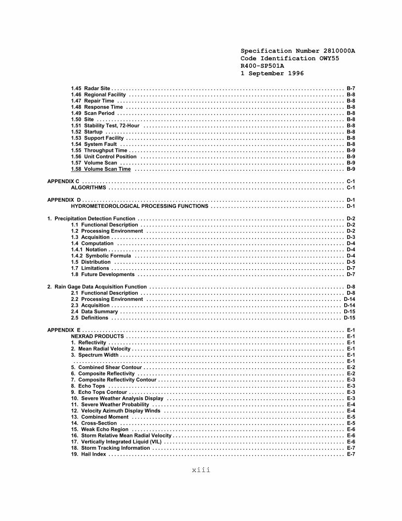
Specification Number 2810000ACode Identification OWY55 R400-SP501A 1 September 1996
xiii
1.45 Radar Site . . . . . . . . . . . . . . . . . . . . . . . . . . . . . . . . . . . . . . . . . . . . . . . . . . . . . . . . . . . . . . . . . . . . . . . . . . . . . . . . B-71.46 Regional Facility . . . . . . . . . . . . . . . . . . . . . . . . . . . . . . . . . . . . . . . . . . . . . . . . . . . . . . . . . . . . . . . . . . . . . . . . . . B-81.47 Repair Time . . . . . . . . . . . . . . . . . . . . . . . . . . . . . . . . . . . . . . . . . . . . . . . . . . . . . . . . . . . . . . . . . . . . . . . . . . . . . . B-81.48 Response Time . . . . . . . . . . . . . . . . . . . . . . . . . . . . . . . . . . . . . . . . . . . . . . . . . . . . . . . . . . . . . . . . . . . . . . . . . . . B-81.49 Scan Period . . . . . . . . . . . . . . . . . . . . . . . . . . . . . . . . . . . . . . . . . . . . . . . . . . . . . . . . . . . . . . . . . . . . . . . . . . . . . . B-81.50 Site . . . . . . . . . . . . . . . . . . . . . . . . . . . . . . . . . . . . . . . . . . . . . . . . . . . . . . . . . . . . . . . . . . . . . . . . . . . . . . . . . . . . . B-81.51 Stability Test, 72-Hour . . . . . . . . . . . . . . . . . . . . . . . . . . . . . . . . . . . . . . . . . . . . . . . . . . . . . . . . . . . . . . . . . . . . . B-81.52 Startup . . . . . . . . . . . . . . . . . . . . . . . . . . . . . . . . . . . . . . . . . . . . . . . . . . . . . . . . . . . . . . . . . . . . . . . . . . . . . . . . . . B-81.53 Support Facility . . . . . . . . . . . . . . . . . . . . . . . . . . . . . . . . . . . . . . . . . . . . . . . . . . . . . . . . . . . . . . . . . . . . . . . . . . . B-81.54 System Fault . . . . . . . . . . . . . . . . . . . . . . . . . . . . . . . . . . . . . . . . . . . . . . . . . . . . . . . . . . . . . . . . . . . . . . . . . . . . . B-81.55 Throughput Time . . . . . . . . . . . . . . . . . . . . . . . . . . . . . . . . . . . . . . . . . . . . . . . . . . . . . . . . . . . . . . . . . . . . . . . . . . B-91.56 Unit Control Position . . . . . . . . . . . . . . . . . . . . . . . . . . . . . . . . . . . . . . . . . . . . . . . . . . . . . . . . . . . . . . . . . . . . . . B-91.57 Volume Scan . . . . . . . . . . . . . . . . . . . . . . . . . . . . . . . . . . . . . . . . . . . . . . . . . . . . . . . . . . . . . . . . . . . . . . . . . . . . . B-91.58 Volume Scan Time . . . . . . . . . . . . . . . . . . . . . . . . . . . . . . . . . . . . . . . . . . . . . . . . . . . . . . . . . . . . . . . . . . . . . . . . B-9
APPENDIX C . . . . . . . . . . . . . . . . . . . . . . . . . . . . . . . . . . . . . . . . . . . . . . . . . . . . . . . . . . . . . . . . . . . . . . . . . . . . . . . . . . . . . . . . . . C-1ALGORITHMS . . . . . . . . . . . . . . . . . . . . . . . . . . . . . . . . . . . . . . . . . . . . . . . . . . . . . . . . . . . . . . . . . . . . . . . . . . . . . . . . . C-1
APPENDIX D . . . . . . . . . . . . . . . . . . . . . . . . . . . . . . . . . . . . . . . . . . . . . . . . . . . . . . . . . . . . . . . . . . . . . . . . . . . . . . . . . . . . . . . . . . D-1HYDROMETEOROLOGICAL PROCESSING FUNCTIONS . . . . . . . . . . . . . . . . . . . . . . . . . . . . . . . . . . . . . . . . . . . . . . D-1
1. Precipitation Detection Function . . . . . . . . . . . . . . . . . . . . . . . . . . . . . . . . . . . . . . . . . . . . . . . . . . . . . . . . . . . . . . . . . . . . . . . D-21.1 Functional Description . . . . . . . . . . . . . . . . . . . . . . . . . . . . . . . . . . . . . . . . . . . . . . . . . . . . . . . . . . . . . . . . . . . . . . D-21.2 Processing Environment . . . . . . . . . . . . . . . . . . . . . . . . . . . . . . . . . . . . . . . . . . . . . . . . . . . . . . . . . . . . . . . . . . . . D-21.3 Acquisition . . . . . . . . . . . . . . . . . . . . . . . . . . . . . . . . . . . . . . . . . . . . . . . . . . . . . . . . . . . . . . . . . . . . . . . . . . . . . . . . D-31.4 Computation . . . . . . . . . . . . . . . . . . . . . . . . . . . . . . . . . . . . . . . . . . . . . . . . . . . . . . . . . . . . . . . . . . . . . . . . . . . . . . D-41.4.1 Notation . . . . . . . . . . . . . . . . . . . . . . . . . . . . . . . . . . . . . . . . . . . . . . . . . . . . . . . . . . . . . . . . . . . . . . . . . . . . . . . . . D-41.4.2 Symbolic Formula . . . . . . . . . . . . . . . . . . . . . . . . . . . . . . . . . . . . . . . . . . . . . . . . . . . . . . . . . . . . . . . . . . . . . . . . D-41.5 Distribution . . . . . . . . . . . . . . . . . . . . . . . . . . . . . . . . . . . . . . . . . . . . . . . . . . . . . . . . . . . . . . . . . . . . . . . . . . . . . . . D-51.7 Limitations . . . . . . . . . . . . . . . . . . . . . . . . . . . . . . . . . . . . . . . . . . . . . . . . . . . . . . . . . . . . . . . . . . . . . . . . . . . . . . . . D-71.8 Future Developments . . . . . . . . . . . . . . . . . . . . . . . . . . . . . . . . . . . . . . . . . . . . . . . . . . . . . . . . . . . . . . . . . . . . . . . D-7
2. Rain Gage Data Acquisition Function . . . . . . . . . . . . . . . . . . . . . . . . . . . . . . . . . . . . . . . . . . . . . . . . . . . . . . . . . . . . . . . . . . . D-82.1 Functional Description . . . . . . . . . . . . . . . . . . . . . . . . . . . . . . . . . . . . . . . . . . . . . . . . . . . . . . . . . . . . . . . . . . . . . . D-82.2 Processing Environment . . . . . . . . . . . . . . . . . . . . . . . . . . . . . . . . . . . . . . . . . . . . . . . . . . . . . . . . . . . . . . . . . . . D-142.3 Acquisition . . . . . . . . . . . . . . . . . . . . . . . . . . . . . . . . . . . . . . . . . . . . . . . . . . . . . . . . . . . . . . . . . . . . . . . . . . . . . . . D-142.4 Data Summary . . . . . . . . . . . . . . . . . . . . . . . . . . . . . . . . . . . . . . . . . . . . . . . . . . . . . . . . . . . . . . . . . . . . . . . . . . . . D-152.5 Definitions . . . . . . . . . . . . . . . . . . . . . . . . . . . . . . . . . . . . . . . . . . . . . . . . . . . . . . . . . . . . . . . . . . . . . . . . . . . . . . . D-15
APPENDIX E . . . . . . . . . . . . . . . . . . . . . . . . . . . . . . . . . . . . . . . . . . . . . . . . . . . . . . . . . . . . . . . . . . . . . . . . . . . . . . . . . . . . . . . . . . E-1NEXRAD PRODUCTS . . . . . . . . . . . . . . . . . . . . . . . . . . . . . . . . . . . . . . . . . . . . . . . . . . . . . . . . . . . . . . . . . . . . . . . . . . . E-11. Reflectivity . . . . . . . . . . . . . . . . . . . . . . . . . . . . . . . . . . . . . . . . . . . . . . . . . . . . . . . . . . . . . . . . . . . . . . . . . . . . . . . . . E-12. Mean Radial Velocity . . . . . . . . . . . . . . . . . . . . . . . . . . . . . . . . . . . . . . . . . . . . . . . . . . . . . . . . . . . . . . . . . . . . . . . . . E-13. Spectrum Width . . . . . . . . . . . . . . . . . . . . . . . . . . . . . . . . . . . . . . . . . . . . . . . . . . . . . . . . . . . . . . . . . . . . . . . . . . . . . E-1. . . . . . . . . . . . . . . . . . . . . . . . . . . . . . . . . . . . . . . . . . . . . . . . . . . . . . . . . . . . . . . . . . . . . . . . . . . . . . . . . . . . . . . . . . . . . E-1
5. Combined Shear Contour . . . . . . . . . . . . . . . . . . . . . . . . . . . . . . . . . . . . . . . . . . . . . . . . . . . . . . . . . . . . . . . . . . . . . E-26. Composite Reflectivity . . . . . . . . . . . . . . . . . . . . . . . . . . . . . . . . . . . . . . . . . . . . . . . . . . . . . . . . . . . . . . . . . . . . . . . E-27. Composite Reflectivity Contour . . . . . . . . . . . . . . . . . . . . . . . . . . . . . . . . . . . . . . . . . . . . . . . . . . . . . . . . . . . . . . . . E-38. Echo Tops . . . . . . . . . . . . . . . . . . . . . . . . . . . . . . . . . . . . . . . . . . . . . . . . . . . . . . . . . . . . . . . . . . . . . . . . . . . . . . . . . E-39. Echo Tops Contour . . . . . . . . . . . . . . . . . . . . . . . . . . . . . . . . . . . . . . . . . . . . . . . . . . . . . . . . . . . . . . . . . . . . . . . . . . E-310. Severe Weather Analysis Display . . . . . . . . . . . . . . . . . . . . . . . . . . . . . . . . . . . . . . . . . . . . . . . . . . . . . . . . . . . . . E-311. Severe Weather Probability . . . . . . . . . . . . . . . . . . . . . . . . . . . . . . . . . . . . . . . . . . . . . . . . . . . . . . . . . . . . . . . . . . E-412. Velocity Azimuth Display Winds . . . . . . . . . . . . . . . . . . . . . . . . . . . . . . . . . . . . . . . . . . . . . . . . . . . . . . . . . . . . . . E-413. Combined Moment . . . . . . . . . . . . . . . . . . . . . . . . . . . . . . . . . . . . . . . . . . . . . . . . . . . . . . . . . . . . . . . . . . . . . . . . . E-514. Cross-Section . . . . . . . . . . . . . . . . . . . . . . . . . . . . . . . . . . . . . . . . . . . . . . . . . . . . . . . . . . . . . . . . . . . . . . . . . . . . . E-515. Weak Echo Region . . . . . . . . . . . . . . . . . . . . . . . . . . . . . . . . . . . . . . . . . . . . . . . . . . . . . . . . . . . . . . . . . . . . . . . . . E-616. Storm Relative Mean Radial Velocity . . . . . . . . . . . . . . . . . . . . . . . . . . . . . . . . . . . . . . . . . . . . . . . . . . . . . . . . . . . E-617. Vertically Integrated Liquid (VIL) . . . . . . . . . . . . . . . . . . . . . . . . . . . . . . . . . . . . . . . . . . . . . . . . . . . . . . . . . . . . . . E-618. Storm Tracking Information . . . . . . . . . . . . . . . . . . . . . . . . . . . . . . . . . . . . . . . . . . . . . . . . . . . . . . . . . . . . . . . . . . E-719. Hail Index . . . . . . . . . . . . . . . . . . . . . . . . . . . . . . . . . . . . . . . . . . . . . . . . . . . . . . . . . . . . . . . . . . . . . . . . . . . . . . . . . E-7

Specification Number 2810000ACode Identification OWY55 R400-SP501A 1 September 1996
xiv
20. Mesocyclone . . . . . . . . . . . . . . . . . . . . . . . . . . . . . . . . . . . . . . . . . . . . . . . . . . . . . . . . . . . . . . . . . . . . . . . . . . . . . . E-721. Tornado Vortex Signature . . . . . . . . . . . . . . . . . . . . . . . . . . . . . . . . . . . . . . . . . . . . . . . . . . . . . . . . . . . . . . . . . . . E-822. Storm Structure . . . . . . . . . . . . . . . . . . . . . . . . . . . . . . . . . . . . . . . . . . . . . . . . . . . . . . . . . . . . . . . . . . . . . . . . . . . . E-823. Layer Composite Reflectivity . . . . . . . . . . . . . . . . . . . . . . . . . . . . . . . . . . . . . . . . . . . . . . . . . . . . . . . . . . . . . . . . . E-824. Layer Composite Turbulence . . . . . . . . . . . . . . . . . . . . . . . . . . . . . . . . . . . . . . . . . . . . . . . . . . . . . . . . . . . . . . . . . E-925. User Alert Message . . . . . . . . . . . . . . . . . . . . . . . . . . . . . . . . . . . . . . . . . . . . . . . . . . . . . . . . . . . . . . . . . . . . . . . . . E-926. Radar Coded Message . . . . . . . . . . . . . . . . . . . . . . . . . . . . . . . . . . . . . . . . . . . . . . . . . . . . . . . . . . . . . . . . . . . . . E-1027. Free Text Message . . . . . . . . . . . . . . . . . . . . . . . . . . . . . . . . . . . . . . . . . . . . . . . . . . . . . . . . . . . . . . . . . . . . . . . . E-1128. Surface Rainfall Accumulation . . . . . . . . . . . . . . . . . . . . . . . . . . . . . . . . . . . . . . . . . . . . . . . . . . . . . . . . . . . . . . . E-1129. Storm Total Rainfall Accumulation . . . . . . . . . . . . . . . . . . . . . . . . . . . . . . . . . . . . . . . . . . . . . . . . . . . . . . . . . . . E-1230. Hourly Digital Precipitation Array . . . . . . . . . . . . . . . . . . . . . . . . . . . . . . . . . . . . . . . . . . . . . . . . . . . . . . . . . . . . E-1231. Supplemental Precipitation Data . . . . . . . . . . . . . . . . . . . . . . . . . . . . . . . . . . . . . . . . . . . . . . . . . . . . . . . . . . . . . E-1232. User Selectable Rainfall Accumulation . . . . . . . . . . . . . . . . . . . . . . . . . . . . . . . . . . . . . . . . . . . . . . . . . . . . . . . E-1233. Digital Hybrid Scan Reflectivity . . . . . . . . . . . . . . . . . . . . . . . . . . . . . . . . . . . . . . . . . . . . . . . . . . . . . . . . . . . . . . E-1334. Clutter Filter Control . . . . . . . . . . . . . . . . . . . . . . . . . . . . . . . . . . . . . . . . . . . . . . . . . . . . . . . . . . . . . . . . . . . . . . . E-13
APPENDIX F . . . . . . . . . . . . . . . . . . . . . . . . . . . . . . . . . . . . . . . . . . . . . . . . . . . . . . . . . . . . . . . . . . . . . . . . . . . . . . . . . . . . . . . . . . F-1
. . . . . . . . . . . . . . . . . . . . . . . . . . . . . . . . . . . . . . . . . . . . . . . . . . . . . . . . . . . . . . . . . . . . . . . . . . . . . . . . . . . . . . . . . . . . . . . . . . . . . . F-1
APPENDIX G . . . . . . . . . . . . . . . . . . . . . . . . . . . . . . . . . . . . . . . . . . . . . . . . . . . . . . . . . . . . . . . . . . . . . . . . . . . . . . . . . . . . . . . . . G-1
ACRONYMS/ABBREVIATIONS . . . . . . . . . . . . . . . . . . . . . . . . . . . . . . . . . . . . . . . . . . . . . . . . . . . . . . . . . . . . . . . . . . . . . . . . . . . G-1
APPENDIX H . . . . . . . . . . . . . . . . . . . . . . . . . . . . . . . . . . . . . . . . . . . . . . . . . . . . . . . . . . . . . . . . . . . . . . . . . . . . . . . . . . . . . . . . . . H-1
ADAPTATION PARAMETERS . . . . . . . . . . . . . . . . . . . . . . . . . . . . . . . . . . . . . . . . . . . . . . . . . . . . . . . . . . . . . . . . . . . . . . . . . . . . H-11. Radar Site Latitude/Longitude Coordinate Position: . . . . . . . . . . . . . . . . . . . . . . . . . . . . . . . . . . . . . . . . . H-32. Product Distribution: . . . . . . . . . . . . . . . . . . . . . . . . . . . . . . . . . . . . . . . . . . . . . . . . . . . . . . . . . . . . . . . . . . . H-33. Product Selection to Map Background Pairing . . . . . . . . . . . . . . . . . . . . . . . . . . . . . . . . . . . . . . . . . . . . . H-34. Product to User Display Pairing . . . . . . . . . . . . . . . . . . . . . . . . . . . . . . . . . . . . . . . . . . . . . . . . . . . . . . . . . H-35. Product to Color Mix Pairing (per PUP) . . . . . . . . . . . . . . . . . . . . . . . . . . . . . . . . . . . . . . . . . . . . . . . . . . . H-36. Function Key Definition . . . . . . . . . . . . . . . . . . . . . . . . . . . . . . . . . . . . . . . . . . . . . . . . . . . . . . . . . . . . . . . . H-37. Function Key Turn on Setting (per Display) . . . . . . . . . . . . . . . . . . . . . . . . . . . . . . . . . . . . . . . . . . . . . . . . H-38. Cursor Home Location (per Display) . . . . . . . . . . . . . . . . . . . . . . . . . . . . . . . . . . . . . . . . . . . . . . . . . . . . . . H-49. Preview Area Location (per Display) . . . . . . . . . . . . . . . . . . . . . . . . . . . . . . . . . . . . . . . . . . . . . . . . . . . . . . H-410. Cursor Coordinate Output Location (per Display) . . . . . . . . . . . . . . . . . . . . . . . . . . . . . . . . . . . . . . . . . . . H-411. Data Array(s) Output Location (per Array; per Display) . . . . . . . . . . . . . . . . . . . . . . . . . . . . . . . . . . . . . . . H-412. Symbol Size; Character Size; Line Width . . . . . . . . . . . . . . . . . . . . . . . . . . . . . . . . . . . . . . . . . . . . . . . . . . H-413. Blink Rate . . . . . . . . . . . . . . . . . . . . . . . . . . . . . . . . . . . . . . . . . . . . . . . . . . . . . . . . . . . . . . . . . . . . . . . . . . . . H-414. Inter-character and inter-line spacing of alphanumeric array data . . . . . . . . . . . . . . . . . . . . . . . . . . . . . . H-415. Leader Line to Character or Array Spacing . . . . . . . . . . . . . . . . . . . . . . . . . . . . . . . . . . . . . . . . . . . . . . . . . H-416. Data Type to Line Format Pairing . . . . . . . . . . . . . . . . . . . . . . . . . . . . . . . . . . . . . . . . . . . . . . . . . . . . . . . . . H-517. Task Overload Shedding Priority (per Functional Area) . . . . . . . . . . . . . . . . . . . . . . . . . . . . . . . . . . . . . . . H-518. Product Overload Shedding Priority (per Functional Area; Interface) . . . . . . . . . . . . . . . . . . . . . . . . . . . H-519. Display Preset Center Location (per Display) . . . . . . . . . . . . . . . . . . . . . . . . . . . . . . . . . . . . . . . . . . . . . . . H-520. Overload Warning Threshold (per Overload Type) . . . . . . . . . . . . . . . . . . . . . . . . . . . . . . . . . . . . . . . . . . . H-521. Overload Warning Display (Minimum Time; Maximum Time Following Overload Recovery) . . . . . . . . . H-522. Processor Storage Capacity (On-line) . . . . . . . . . . . . . . . . . . . . . . . . . . . . . . . . . . . . . . . . . . . . . . . . . . . . . H-523. Operational Mode (Initial Setting) . . . . . . . . . . . . . . . . . . . . . . . . . . . . . . . . . . . . . . . . . . . . . . . . . . . . . . . . . H-624. Rain Gage Data Acquisition Computer Access Numbers . . . . . . . . . . . . . . . . . . . . . . . . . . . . . . . . . . . . . H-625. RPG Access Numbers . . . . . . . . . . . . . . . . . . . . . . . . . . . . . . . . . . . . . . . . . . . . . . . . . . . . . . . . . . . . . . . . . . H-626. Meteorological Phenomena for Alerts . . . . . . . . . . . . . . . . . . . . . . . . . . . . . . . . . . . . . . . . . . . . . . . . . . . . . H-627. Communication Timeout Periods . . . . . . . . . . . . . . . . . . . . . . . . . . . . . . . . . . . . . . . . . . . . . . . . . . . . . . . . . H-628. Alert Areas . . . . . . . . . . . . . . . . . . . . . . . . . . . . . . . . . . . . . . . . . . . . . . . . . . . . . . . . . . . . . . . . . . . . . . . . . . . H-6
APPENDIX I . . . . . . . . . . . . . . . . . . . . . . . . . . . . . . . . . . . . . . . . . . . . . . . . . . . . . . . . . . . . . . . . . . . . . . . . . . . . . . . . . . . . . . . . . . . I-1
OPERATIONAL MODES AND SCANNING STRATEGIES . . . . . . . . . . . . . . . . . . . . . . . . . . . . . . . . . . . . . . . . . . . . . . . . . . . . . . . . I-11. OPERATIONAL MODES . . . . . . . . . . . . . . . . . . . . . . . . . . . . . . . . . . . . . . . . . . . . . . . . . . . . . . . . . . . . . . . . . . . . . . . I-1

Specification Number 2810000ACode Identification OWY55 R400-SP501A 1 September 1996
xv
2. SCANNING STRATEGIES . . . . . . . . . . . . . . . . . . . . . . . . . . . . . . . . . . . . . . . . . . . . . . . . . . . . . . . . . . . . . . . . . . . . . . I-13. SELECTION/DESELECTION CRITERIA . . . . . . . . . . . . . . . . . . . . . . . . . . . . . . . . . . . . . . . . . . . . . . . . . . . . . . . . . . . I-1
APPENDIX J METEOROLOGICAL PHENOMENA FOR ALERTS . . . . . . . . . . . . . . . . . . . . . . . . . . . . . . . . . . . . . . . . . . . . . . . . J-1a. Grid Group . . . . . . . . . . . . . . . . . . . . . . . . . . . . . . . . . . . . . . . . . . . . . . . . . . . . . . . . . . . . . . . . . . . . . . . . . . . J-1b. Volume Group . . . . . . . . . . . . . . . . . . . . . . . . . . . . . . . . . . . . . . . . . . . . . . . . . . . . . . . . . . . . . . . . . . . . . . . . J-1c. Forecast Group . . . . . . . . . . . . . . . . . . . . . . . . . . . . . . . . . . . . . . . . . . . . . . . . . . . . . . . . . . . . . . . . . . . . . . . J-1
APPENDIX K . . . . . . . . . . . . . . . . . . . . . . . . . . . . . . . . . . . . . . . . . . . . . . . . . . . . . . . . . . . . . . . . . . . . . . . . . . . . . . . . . . . . . . . . . . K-1RADAR CODED MESSAGE CODE . . . . . . . . . . . . . . . . . . . . . . . . . . . . . . . . . . . . . . . . . . . . . . . . . . . . . . . . . . . . . . . . K-1Header . . . . . . . . . . . . . . . . . . . . . . . . . . . . . . . . . . . . . . . . . . . . . . . . . . . . . . . . . . . . . . . . . . . . . . . . . . . . . . . . . . . . . . . K-1Part A: Reflectivity . . . . . . . . . . . . . . . . . . . . . . . . . . . . . . . . . . . . . . . . . . . . . . . . . . . . . . . . . . . . . . . . . . . . . . . . . . . . . K-1Part B: VAD Winds . . . . . . . . . . . . . . . . . . . . . . . . . . . . . . . . . . . . . . . . . . . . . . . . . . . . . . . . . . . . . . . . . . . . . . . . . . . . K-4Part C: Remarks . . . . . . . . . . . . . . . . . . . . . . . . . . . . . . . . . . . . . . . . . . . . . . . . . . . . . . . . . . . . . . . . . . . . . . . . . . . . . . K-5End of Message . . . . . . . . . . . . . . . . . . . . . . . . . . . . . . . . . . . . . . . . . . . . . . . . . . . . . . . . . . . . . . . . . . . . . . . . . . . . . . . K-8
Appendix L . . . . . . . . . . . . . . . . . . . . . . . . . . . . . . . . . . . . . . . . . . . . . . . . . . . . . . . . . . . . . . . . . . . . . . . . . . . . . . . . . . . . . . . . . . . L-1This Appendix Intentionally Left Blank. . . . . . . . . . . . . . . . . . . . . . . . . . . . . . . . . . . . . . . . . . . . . . . . . . . . . . . . . . . . . L-1
APPENDIX M . . . . . . . . . . . . . . . . . . . . . . . . . . . . . . . . . . . . . . . . . . . . . . . . . . . . . . . . . . . . . . . . . . . . . . . . . . . . . . . . . . . . . . . . . M-1
NEXRAD ACCESS ROADS . . . . . . . . . . . . . . . . . . . . . . . . . . . . . . . . . . . . . . . . . . . . . . . . . . . . . . . . . . . . . . . . . . . . . . . . . . . . . . . M-11. DESCRIPTION . . . . . . . . . . . . . . . . . . . . . . . . . . . . . . . . . . . . . . . . . . . . . . . . . . . . . . . . . . . . . . . . . . . . . . . . . . . . . . M-12. PERFORMANCE SPECIFICATION . . . . . . . . . . . . . . . . . . . . . . . . . . . . . . . . . . . . . . . . . . . . . . . . . . . . . . . . . . . . . . M-1
FIGURES
FIGURE 3-1 FUNCTIONAL AREA OVERVIEW . . . . . . . . . . . . . . . . . . . . . . . . . . . . . . . . . . . . . . . . . . . . . . . . . . . . . . . . . . . . . . . 3-7FIGURE 3-2 NEXRAD UNITS AND SITES (EXAMPLE) . . . . . . . . . . . . . . . . . . . . . . . . . . . . . . . . . . . . . . . . . . . . . . . . . . . . . . . 3-11FIGURE 3-3 NEXRAD UNIT INTERFACES . . . . . . . . . . . . . . . . . . . . . . . . . . . . . . . . . . . . . . . . . . . . . . . . . . . . . . . . . . . . . . . . . 3-12FIGURE 3-4 NEXRAD UNIT OPERATIONAL FUNCTIONAL FLOW DIAGRAM . . . . . . . . . . . . . . . . . . . . . . . . . . . . . . . . . . . . . 3-31FIGURE 3-5 STANDARD NAME PLATE, WS-N-SD001A . . . . . . . . . . . . . . . . . . . . . . . . . . . . . . . . . . . . . . . . . . . . . . . . . . . . . . 3-42FIGURE 3-6 CLUTTER SUPPRESSION CAPABILITY CHARACTERIZATION FOR LINEAR TIME INVARIANT CLUTTER FILTERING . . . . . . . . . . . . . . . . . . . . . . . . . . . . . . . . . . . . . . . . . . . . . . . . . . . . . . . . . . . . . . . . . 3-72FIGURE K-1 1/16 LIMITED FINE MESH GRID . . . . . . . . . . . . . . . . . . . . . . . . . . . . . . . . . . . . . . . . . . . . . . . . . . . . . . . . . . . . . . . K-2
TABLES
TABLE 3-1 NEXRAD PRINCIPAL USER ORGANIZATION OVERVIEW . . . . . . . . . . . . . . . . . . . . . . . . . . . . . . . . . . . . . . . . . . 3-13TABLE 3-2 NEXRAD DATA FLOW . . . . . . . . . . . . . . . . . . . . . . . . . . . . . . . . . . . . . . . . . . . . . . . . . . . . . . . . . . . . . . . . . . . . . . . 3-15TABLE 3-3 PEAK REQUEST RATES . . . . . . . . . . . . . . . . . . . . . . . . . . . . . . . . . . . . . . . . . . . . . . . . . . . . . . . . . . . . . . . . . . . . . 3-19TABLE 3-4 SYSTEM RESPONSE TIME REQUIREMENTS . . . . . . . . . . . . . . . . . . . . . . . . . . . . . . . . . . . . . . . . . . . . . . . . . . . . 3-20TABLE 3-5 NEXRAD UNIT CONFIGURATIONS . . . . . . . . . . . . . . . . . . . . . . . . . . . . . . . . . . . . . . . . . . . . . . . . . . . . . . . . . . . . . 3-26TABLE 3-6 KEY OPERATIONAL FUNCTIONS AND SUBFUNCTIONS . . . . . . . . . . . . . . . . . . . . . . . . . . . . . . . . . . . . . . . . . . . 3-32TABLE 3-8 MAXIMUM ALLOWABLE BIAS IN REFLECTIVITY ESTIMATES DUE TO THE CLUTTER
SUPPRESSION DEVICE . . . . . . . . . . . . . . . . . . . . . . . . . . . . . . . . . . . . . . . . . . . . . . . . . . . . . . . . . . . . . . . . . . . . . . . . 3-73TABLE 3-9 NEXRAD COMMUNICATIONS LINK CHARACTERISTICS . . . . . . . . . . . . . . . . . . . . . . . . . . . . . . . . . . . . . . . . . . 3-112TABLE A-1 NEXRAD STANDARDS AND CONVENTIONS AT EACH INTERFACE LAYER . . . . . . . . . . . . . . . . . . . . . . . . . . . . A-6TABLE A-2 NEXRAD TRANSMISSION LINE CHARACTERISTICS . . . . . . . . . . . . . . . . . . . . . . . . . . . . . . . . . . . . . . . . . . . . . . . A-7TABLE D-1 MINIMAL SCAN MODE REQUIREMENTS NECESSARY FOR DETECTING PRECIPITATION . . . . . . . . . . . . . . . D-7TABLE D-2 SUMMARY OF INCOMING MESSAGE FORMATS . . . . . . . . . . . . . . . . . . . . . . . . . . . . . . . . . . . . . . . . . . . . . . . . . D-10TABLE D-3 SUMMARY OF VALID PEDTSEP CODES . . . . . . . . . . . . . . . . . . . . . . . . . . . . . . . . . . . . . . . . . . . . . . . . . . . . . . . . D-11TABLE D-4 VALID DURATION CODE VARIABLE SPECIFIERS . . . . . . . . . . . . . . . . . . . . . . . . . . . . . . . . . . . . . . . . . . . . . . . . D-13TABLE E-1 NEXRAD PRODUCTS . . . . . . . . . . . . . . . . . . . . . . . . . . . . . . . . . . . . . . . . . . . . . . . . . . . . . . . . . . . . . . . . . . . . . . . . E-15TABLE H-1 NEXRAD ADAPTATION PARAMETERS . . . . . . . . . . . . . . . . . . . . . . . . . . . . . . . . . . . . . . . . . . . . . . . . . . . . . . . . . . H-2
Specification Number 2810000ACode Identification OWY55 R400-SP501A 1 September 1996
1-1
1. SCOPE
This document establishes the performance, design, development and testconstraints for the NEXRAD System (See Appendix-B). This documentconstitutes the NEXRAD System Specification, Type A, as defined by MIL-STD-490. Thus, the remaining sections are as follows:
Section 2 - Applicable Documents
Section 3 - Requirements
Section 4 - Quality Assurance

Specification Number 2810000ACode Identification OWY55 R400-SP501A 1 September 1996
1-2
This Page Intentionally Left Blank
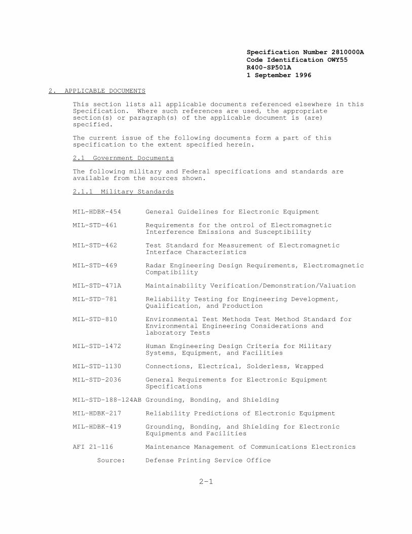
Specification Number 2810000ACode Identification OWY55 R400-SP501A 1 September 1996
2-1
2. APPLICABLE DOCUMENTS
This section lists all applicable documents referenced elsewhere in thisSpecification. Where such references are used, the appropriatesection(s) or paragraph(s) of the applicable document is (are)specified.
The current issue of the following documents form a part of thisspecification to the extent specified herein.
2.1 Government Documents
The following military and Federal specifications and standards areavailable from the sources shown.
2.1.1 Military Standards
MIL-HDBK-454 General Guidelines for Electronic Equipment
MIL-STD-461 Requirements for the ontrol of ElectromagneticInterference Emissions and Susceptibility
MIL-STD-462 Test Standard for Measurement of ElectromagneticInterface Characteristics
MIL-STD-469 Radar Engineering Design Requirements, ElectromagneticCompatibility
MIL-STD-471A Maintainability Verification/Demonstration/Valuation
MIL-STD-781 Reliability Testing for Engineering Development,Qualification, and Production
MIL-STD-810 Environmental Test Methods Test Method Standard forEnvironmental Engineering Considerations andlaboratory Tests
MIL-STD-1472 Human Engineering Design Criteria for MilitarySystems, Equipment, and Facilities
MIL-STD-1130 Connections, Electrical, Solderless, Wrapped
MIL-STD-2036 General Requirements for Electronic EquipmentSpecifications
MIL-STD-188-124AB Grounding, Bonding, and Shielding
MIL-HDBK-217 Reliability Predictions of Electronic Equipment
MIL-HDBK-419 Grounding, Bonding, and Shielding for ElectronicEquipments and Facilities
AFI 21-116 Maintenance Management of Communications Electronics
Source: Defense Printing Service Office
Specification Number 2810000ACode Identification OWY55 R400-SP501A 1 September 1996
2-2
700 Robbins Avenue Philadelphia, PA. 19111-5094
2.1.2 Federal Documents
FED-STD-595A Colors
OSHA-29 CFR 1910 OSHA Safety and Health Standards
Source: Superintendent of DocumentsU.S. Government Printing OfficeWashington, DC 20402
NWS Transient Susceptibility Standard May 1978)
National Weather Service Operations Manual
Source: National Weather Service 1325 East-West Highway Silver Spring, MD 20910
AC 70/7460-IF FAA Advisory Circular, Obstruction Marking andLighting
DOT/FAA Order 6000.27 Transmittal of Maintenance Philosophy SteeringGroup Report
Source: Federal Aviation Administration Washington, DC 20591
Manual of Regulations and Procedures for Federal Radio FrequencyManagement, National Telecommunications and Information Administration
R400-AR401 NEXRAD Algorithm Report
R400-IN401 NEXRAD Interface Control Document
Source: NEXRAD Operational Support Facility (OSF)Norman, OK 73072
PUP Site Survey Instructions and Information Package. Rev. 6.
Source: NEXRAD System Program Office (SPO1), Facilities Branch1325 East-West HighwaySilver Spring, MD 20910
Specification Number 2810000ACode Identification OWY55 R400-SP501A 1 September 1996
2-3
2.2 Non-Government Documents
The following non-Government documents are available from the sourcesshown.
2.2.1 American National Standards Institute (ANSI) Standards
ANSI x3.4 American Standard Code for Information Interchange
ANSI C95.1-1982 Safety Levels With Respect to Human Exposure to RadioFrequency Electromagnetic Fields, 300 KHz to 100 GHz
Source: ANSI, Inc.1430 BroadwayNew York, NY 10018
2.2.2 Electronic Industries Association (EIA) Documents
EIA-195-C Electrical and Mechanical Characteristics forTerrestrial Microwave Relay System Antennas andPassive Reflectors
EIA/TIA-222-E Structural Standards for Steel Antenna Towers andAntenna Supporting Structures
RS-449 General Purpose 37 Position and 9 Position Interfacefor Data Circuit-Terminating Equipment EmployingSerial Binary Data
Filtering, Electronic Equipment, Bulletin No. 9
Source: EIAEngineering Department2001 Eye Street, NWWashington, DC 20006
Specification Number 2810000ACode Identification OWY55 R400-SP501A 1 September 1996
2-4
2.2.3 Other Non-Government Documents
NFPA No. 70-1971 National Electrical Code
Source: National Fire Protection Association Batterymarch ParkQuincy, MA 02269
IEEE 200-75 Reference Designations for Electrical and ElectronicParts and Equipment
Source: IEEE Service Center445 Hoes LanePiscataway, NJ 08854
ASTM Standards
Source: American Society for Testing Materials 1916 Race StreetPhiladelphia, PA 19103
CCITT Consultative Committee for International Telegraph andTelephone
Source: Omnicon, Inc.115 Park St, S.E.Vienna, VA 22180
2.3 Precedence of Documents
An attempt has been made to prevent conflicts between this Specificationand the referenced documents. However, in the event of a conflictbetween requirements, the following order of precedence (highest=1)shall apply:
1. NEXRAD System Specification
2. Military Standards
3. Federal Standards
4. ANSI Standards
5. EIA Standards
6. Other

Specification Number 2810000ACode Identification OWY55 R400-SP501A 1 September 1996
1Defined in Appendix B.
3-1
3. REQUIREMENTS
This section delineates the performance and design requirements for theNEXRAD System. Throughout this document many performance requirementsare stated as integer numbers. A minimum precision of 2 decimal placesis assumed for all performance requirements given as an integer.
3.1 System Definition
The NEXRAD System comprises Doppler radars, communications, dataprocessing hardware and software, display and data entry equipment,documentation, and certain facilities and support capabilities requiredto detect, process, distribute, and display weather information in amanner which allows the Department of Commerce (DOC), the Department ofDefense (DOD) and the Department of Transportation (DOT) to fulfilltheir mission needs.
3.1.1 General Description
A general description of the NEXRAD System and its functions is providedin the following paragraphs.
3.1.1.1 System Users
The system users include both principal users and other users1.
3.1.1.1.1 Principal Users
The principal users of the NEXRAD System are operationally orientedagencies within the participating departments (DOC, DOD, and DOT) whichuse weather radar information to perform or support their activities. These activities include warning of hazardous weather and flash floodprediction, predicting weather conditions, ensuring safety of flight, protecting base resources, and planning military missions.
Within DOC, the National Weather Service (NWS), a component of theNational Oceanic and Atmospheric Administration (NOAA), is the FederalGovernment's principal civilian meteorological agency. As such, itrequires weather radar information to fulfill its assignedresponsibilities. This information is required at Weather ServiceForecast Offices (WSFOs), Weather Service Offices (WSOs), River ForecastCenters (RFCs), the National Meteorological Center (NMC), the HurricaneCenters (HCs), and the National Severe Storms Forecast Center (NSSFC).
In the case of DOD, the Air Force's Air Weather Service (AWS) is theprincipal user agency which provides meteorological services to the AirForce, the Army, and certain other DOD elements. The Navy's NavalOceanography Command (NOC) is the principal meteorological agency whichsupports the Navy, Marine Corps, and other elements of DOD. AWSrequires weather radar information at its Base Weather Stations (BWSs)and at the Air Force Global Weather Central (AFGWC). NOC requiresweather radar information at its Naval Oceanography Command Detachments(NOCDs).

Specification Number 2810000ACode Identification OWY55 R400-SP501A 1 September 1996
2DEfined in Appendix B.
3Defined in Appendix B.
3-2
In the case of DOT, the Federal Aviation Administration (FAA), as theprincipal civilian agency for ensuring air traffic safety, requiresweather radar information. This information is required at Air Route
Traffic Control Centers (ARTCCs), Terminal Radar Control facilities(TRACONs), airport towers, Flight Service Stations (FSSs), and the FAA'sSystem Command Center (SCC).
3.1.1.1.2 Other Users
Other users of the NEXRAD System include Federal Government agenciesother than the principal users; state and local government agencies; andprivate sector users such as airline companies, consultingmeteorologists, the media, and university laboratories. (Selectedweather radar information will be made available to these usersaccording to policy established by NWS.)
3.1.1.2 Product Generation
To support the common needs of the principal and other users for weatherradar information, the NEXRAD System will generate products which can beused for distribution and presentation to operational personnel. Theseinclude base products, derived products, alphanumeric products, and derived data array products2.
The base products consist of reflectivity, mean radial velocity, andradial velocity spectrum width (standard deviation) estimates presentedin a format suitable for display on a color graphic display. Thederived products provide processed radar data, concentrated to providelarge volumes and varieties of data in a form suitable for display oncolor graphic displays and, to the extent possible, requiring minimuminterpretive effort. The alphanumeric products provide processed radardata for users without a graphic display capability. The derived dataarray products provide data in a nondisplayable format for transmissionto systems external to the NEXRAD System for further processing.
Product generation will be automated to the extent feasible. However,at selected sites, an interactive display and data entry capability willbe available for human analysis of radar data and assistance in thegeneration of certain radar products.
The Radar Product Generation (RPG) function will, where feasible, becollocated with both a radar (antenna) site and one principal user site.
3.1.1.3 Product Distribution
The NEXRAD System will distribute products to the operationalfacilities3 of the principal users and have an access capability so thatother users can obtain selected products.
Specification Number 2810000ACode Identification OWY55 R400-SP501A 1 September 1996
4Defined in Appendix B.
5In order to calibrate raunfall rates, NEXRAD will automatically request andreceive data from Rain Gage Acqusisition Computers (RGDAC).
3-3
3.1.1.3.1 Principal User Product Distribution
In the case of NWS, operational personnel at local facilities(SeeAppendix-B) (WSFOs and WSOs) will automatically be provided productsfrom a preselected (usually collocated) RPG. Certain WSFOs may alsoregularly be provided products from one or more additional preselectedRPGs since their geographic area of responsibility is usually largerthan for WSOs. WSFOs and WSOs may choose products from the preselectedRPG(s) for regular receipt or on-demand call-up, subject only to theircommunications bandwidth limitations. In addition, WSFOs and WSOs willbe able to obtain a limited number of products from any other RPG in theconterminous United States on a request basis.
In the case of NWS, regional facilities and national facilities4 will beprovided selected products based on their needs. For each RFC, precipitation related products will be made available from each RPG within its area of responsibility. Each RFC may choose products fromany RPG within its area of responsibility via dial-up requests.5 Forthe NWS national centers (NMC, the HCs, and NSSFC), relatively lowresolution products will be routinely made available from each relevantRPG. In addition, the national centers will be able to request higherresolution products from any RPG within the conterminous United Stateswhen needed.
In the case of DOD, operational personnel at BWSs and NOCDs willautomatically be provided products from a preselected RPG. In the caseof certain BWSs, the radar will be situated on or near the base itself. The BWSs and NOCDs may choose any product from the preselected RPG forregular receipt or on-demand call-up, subject only to theircommunications bandwidth limitations. In addition, BWSs and NOCDs willbe able to obtain a limited number of products from any other RPG on arequest basis.
The only DOD national facility which requires products is AFGWC. (DODhas no applicable regional facilities.) It, like the NWS nationalcenters, will routinely have available low resolution products and willbe able to request more detailed products from any RPG.
In the case of the FAA, the NEXRAD System will provide products to allARTCCs. The Center Weather Service Unit (CWSU) in each ARTCC will beprovided with products from every RPG within, or with extensive radarcoverage within, its area boundary. (However, the further processing ofthe data received at the CWSU and its distribution to controllers withinthe ARTCC and to personnel at other FAA operational facilities will bethe responsibility of the FAA and will not be a part of thisacquisition.) If a NEXRAD radar is sited near an airport/terminal, basedata* will be sent directly to the TRACON in cases where this approachis selected by the FAA. In the event an RDA is situated near an airport

Specification Number 2810000ACode Identification OWY55 R400-SP501A 1 September 1996
3-4
and the RPG is remote from the RDA, the TRACON may interface directlywith the RDA. In addition, the NEXRAD System will provide thecapability for FAA operational facilities to obtain a limited number ofproducts from any other RPG in the conterminous United States on arequest basis.
3.1.1.3.2 Other User Products
Other users will have access to selected products, according to policyto be established by NWS, although no equipment or communicationsfacilities will be provided in the NEXRAD System for their support,except for interface ports and modems to permit access to products.
3.1.1.4 Principal User Processing and Display
Each of the principal users of the NEXRAD System will require aprocessing and display capability at operational facilities. Thiscapability will be used by operational personnel for the selection,
analysis, and further annotation and distribution of products generatedat an RPG.
For NWS, AWS, and NOC, user processing and display capabilities will bea part of this acquisition. The FAA, however, may acquire its own userprocessing and display capability outside the scope of this acquisition.
For each of the principal users, the processing and display capabilitieswill support the routine display of selected current products, thecall-up of other products (both current and earlier versions), theannotation of products and their further distribution to the principaluser external systems,(See Appendix-B) and the archiving of selectedproducts.
3.1.1.5 Radar Siting
The NEXRAD radar (antenna) sites will be specified by the Government tomeet the area and point coverage requirements of the principal users. These sites will be within the conterminous United States; in Alaska,Hawaii, and Puerto Rico; and at selected overseas locations. A numberof these sites are expected to be in the vicinity of selected airportsto provide airport and terminal coverage.
Whenever feasible, a radar site will be collocated with a principal usersite. NEXRAD network sites(See Appendix-B) will normally be collocatedwith an NWS operational facility, such as a WSFO. NEXRAD local warningsites(See Appendix-B) will normally be collocated with or near anoperational facility of the applicable department. (In this document,the term "local warning" does not refer to the WSR-74C or other similarradars operated by NWS which may elsewhere be referred to as "localwarning" radars.)
3.1.1.6 Support Facilities
The NEXRAD system includes support facilities (See Appendix-B) to assuresatisfactory equipment operation and depot maintenance; provide trainingfor operational and maintenance personnel; and support development,
Specification Number 2810000ACode Identification OWY55 R400-SP501A 1 September 1996
3-5
test, and evaluation activities.
3.1.1.6.1 Maintenance and Supply Depots
A centralized maintenance and supply depot will supports all NEXRADequipment. Depot activities are performed at the descretion of theGovernment.
The maintenance and supply depot will contains one NEXRAD Units(SeeAppendix-B), including radar, data processing, and display and dataentry equipment configured as at an operational site. In addition,other support hardware and software required for the maintenancefunction, related documentation, spare parts, and consumable suppliesare will be located at the depot.
3.1.1.6.2 Maintenance Training Facility
NEXRAD maintenance training facilities are located at two existingprincipal user's training sites. Each facility contains NEXRADequipment, including radar, data processing, and display and data entryhardware, and appropriate test software, dedicated to the hardwaremaintenance training function.
3.1.1.6.3 Operational Training Facility
NEXRAD system operational training facilities are located at existingprincipal users' training sites. Each training facility possess theequipment necessary for operational training including a data playbackcapability.
3.1.1.6.4 Operational Support Facility
An Operational Support Facility (OSF) is established at Norman, Oklahomato provide support to the NEXRAD System. This facility will supportstest and evaluation activities and provides training the initial cadreof agency personnel.
To support test and evaluation activities, the OSF includes datarecording, data playback, and data analysis capabilities, some parts ofwhich use Government Furnished Property (GFP). Radar data sets,recorded in climatologically different geographical areas and underdifferent meteorological conditions, will are also provided by theGovernment to the OSF to support test and evaluation of the dataprocessing, distribution, and display portions of the NEXRAD System.
To support maintenance, enhancement, and distribution of the NEXRADSystem operational software after an Initial Operating Capability (IOC)has been achieved, support software (such as assemblers, compilers,operating systems, test aids, and adaptation data generation software)shall be supplied. Support hardware (such as simulation equipment, datastorage devices, and printers) shall also be supplied to support thesoftware maintenance and enhancement functions.
Specification Number 2810000ACode Identification OWY55 R400-SP501A 1 September 1996
3-6
3.1.1.7 Functional Areas
The NEXRAD System/Segment Specification has been defined in terms ofthe following functional areas:
1. Radar Data Acquisition
2. Radar Product Generation
3. Principal User Processing
4. Communications
5. Facilities
6. Support
An overview of the NEXRAD System functional areas, together with anidentification of the functions of each area, is provided in Figure 3-1. Functional area requirements are presented in more detail in Section 3.7of this document.
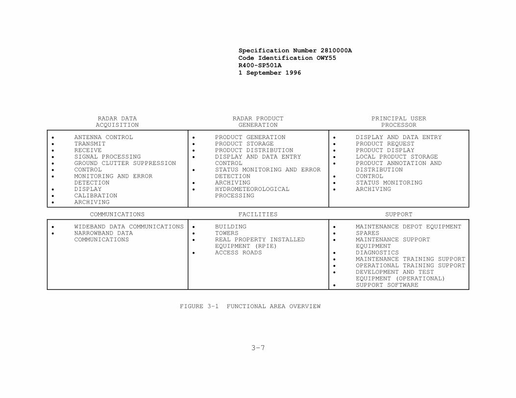
Specification Number 2810000ACode Identification OWY55 R400-SP501A 1 September 1996
3-7
RADAR DATAACQUISITION
RADAR PRODUCTGENERATION
PRINCIPAL USERPROCESSOR
• ANTENNA CONTROL• TRANSMIT • RECEIVE • SIGNAL PROCESSING • GROUND CLUTTER SUPPRESSION • CONTROL • MONITORING AND ERROR
DETECTION • DISPLAY• CALIBRATION• ARCHIVING
• PRODUCT GENERATION• PRODUCT STORAGE• PRODUCT DISTRIBUTION• DISPLAY AND DATA ENTRY
CONTROL• STATUS MONITORING AND ERROR
DETECTION• ARCHIVING• HYDROMETEOROLOGICAL
PROCESSING
• DISPLAY AND DATA ENTRY• PRODUCT REQUEST• PRODUCT DISPLAY • LOCAL PRODUCT STORAGE • PRODUCT ANNOTATION AND
DISTRIBUTION • CONTROL • STATUS MONITORING • ARCHIVING
COMMUNICATIONS FACILITIES SUPPORT
• WIDEBAND DATA COMMUNICATIONS• NARROWBAND DATA
COMMUNICATIONS
• BUILDING• TOWERS• REAL PROPERTY INSTALLED
EQUIPMENT (RPIE)• ACCESS ROADS
• MAINTENANCE DEPOT EQUIPMENT• SPARES• MAINTENANCE SUPPORT
EQUIPMENT• DIAGNOSTICS• MAINTENANCE TRAINING SUPPORT• OPERATIONAL TRAINING SUPPORT• DEVELOPMENT AND TEST
EQUIPMENT (OPERATIONAL)• SUPPORT SOFTWARE
FIGURE 3-1 FUNCTIONAL AREA OVERVIEW
Specification Number 2810000ACode Identification OWY55 R400-SP501A 1 September 1996
3-8
It is the Government's objective to encourage innovation in meeting thestated requirements. Accordingly, a system design may be selected thatallocates functions to equipment items and computer programs in a mannerdifferent than implied by the functional area breakdown, provided all ofthe system requirements are met. Specifically, conclusions should notbe drawn, unless explicitly stated, regarding the relationship between aphysical location (site) and the requirements of an individualfunctional area.
3.1.1.7.1 Radar Data Acquisition
The Radar Data Acquisition (RDA) functional area includes the Dopplerradars which are located at the radar sites. This functional area alsoincludes hardware and software required to perform the signalprocessing, clutter suppression, control, monitoring and errordetection, display, calibration, and archiving functions related toradar operation.
3.1.1.7.2 Radar Product Generation
The Radar Product Generation (RPG) functional area includes all hardwareand software required for real time generation, storage, anddistribution of products for operational use. It also includes hardwareand software required for control, status monitoring and errordetection, archiving, and hydrometeorological processing. To the extentrequired, this functional area includes display and data entry hardwareand software provided for human participation in the generation of theproducts.
3.1.1.7.3 Principal User Processing
The Principal User Processing (PUP) functional area includes allhardware and software required for the request, display, local storage,and local annotation and distribution of products by operationalpersonnel (such as meteorologists and forecasters) of the principal useragencies. It also includes the hardware and software required for localcontrol, status monitoring, and archiving.
3.1.1.7.4 Communications
The Communications functional area includes the hardware and softwarerequired at NEXRAD sites to transmit and receive weather radar data viadedicated or dial-up narrowband links.
It also includes any hardware and software, including communicationsequipment, needed for wideband links that may be required fortransmission of data between noncollocated radar sites and principaluser sites.
3.1.1.7.5 Facilities
The Facilities functional area includes construction and modification ofbuildings, construction of towers, provision and installation of RealProperty Installed Equipment (RPIE) such as power generation and airconditioning equipment, and construction of access roads which areneeded in support of the RDA, RPG, PUP, Communications, and Support
Specification Number 2810000ACode Identification OWY55 R400-SP501A 1 September 1996
3-9
functional areas.
3.1.1.7.6 Support
The Support functional area includes logistics, training, developmentand test, and support software functions. For logistics, the Supportfunctional area includes maintenance depot equipment, spares,maintenance support equipment, and diagnostics. For training, itincludes support for both maintenance and operational training. Fordevelopment and test, it includes operational equipment for the OSF. For support software, it includes capabilities required for thedevelopment, test, maintenance, enhancement, and distribution of theoperational software.
3.1.2 Missions
DOC, DOD, and DOT have major weather related missions andresponsibilities that require weather radar information.
3.1.2.1 Department of Commerce Missions
DOC, through the National Weather Service (NWS), is the principalcivilian meteorological agency of the Federal Government. Specifically,DO is responsible for detection of hazardous weather such as severethunderstorms, tornadoes, excessive rainfalls, and winter weatherevents; and warning the public. It is also responsible for providingessential weather information to other activities such as civilianaviation, marine, agricultural and forestry operations, and the entireriver and flood prediction program. DOC operates many weather radarsand uses information from some radars operated by DOD and DOT to meetthese responsibilities.
3.1.2.2 Department of Defense Missions
Within DOD, the Air Force's Air Weather Service (AWS) provides worldwidemeteorological and aerospace environmental services to the Air Force,Army, and certain other DOD elements; the Naval Oceanography Command(NOC) supports the Navy, Marine Corps, and some other elements of DOD. These organizations are responsible for providing and relaying severeweather warnings for the protection of DOD resources and personnel,providing weather information to aid the decision making process atspecific locations, and supporting military aviation. To meet theseresponsibilities, DOD operates weather radars in the United States andoverseas and uses information from these and from DOC and DOT radars inthe conterminous United States.
3.1.2.3 Department of Transportation Missions
DOT, through its Federal Aviation Administration (FAA), is responsiblefor the safe and efficient utilization of United States airspace. Inmeeting these responsibilities, the FAA provides information on thelocation and intensity of potentially hazardous weather conditions topilots and others concerned with aviation. In recent years, there hasbeen an increased emphasis on providing real time hazardous weatherinformation. DOT has no weather radars and presently obtains itsinformation from its own air traffic control radars (not designed for
Specification Number 2810000ACode Identification OWY55 R400-SP501A 1 September 1996
3-10
weather detection) and from NWS radars via remote displays, other NWSproducts, and NWS personnel located at FAA facilities.
3.1.2.4 System Mission
The mission of the NEXRAD System is the acquisition, processing, anddistribution of weather radar information to aid in reducing loss oflife, injuries, and damage to property. The radar system addresses thecommon need among the three Federal departments (DOC, DOD, and DOT) forinformation on the present location, severity, and movement of weatherphenomena, both routine and hazardous (including tornadoes, severethunderstorms, heavy precipitation, tropical cyclones, hail, high winds,and severe turbulence) throughout the United States and at selectedoverseas locations. The NEXRAD System will also provide routineinformation useful for monitoring and assessing general weatherconditions such as rainfall amounts and distribution.
3.1.3 System Diagrams
In addition to the functional area overview (Figure 3-1) alreadypresented, the following diagrams are also presented:
1. Figure 3-2 is an example of three possible NEXRAD Unitconfigurations. Configuration 1 consists of RDA 1, RPG 1and its operational position (RPGOP 1), and associatedPUPs(See Appendix-B) 1A and 1B. Configuration 2 consists ofRDA 2, RPG 2, and its RPGOP 2, and associated PUPs 2A and2B. Configuration 3 consists of RDA 3, RPG 3, andassociated PUPS 3A and 3B. The boxes designated as sitesrepresent distinct geographic locations. Thus RDA 1, RPG 1,RPGOP 1, and PUP 2A are collocated. That is, in thisexample, all of the equipment needed to perform theirfunctions is located at one WSFO. Sites C and D, althoughboth associated PUPs of Unit 1, are not collocated with anyother equipment of Unit 1. Similarly, although PUP 2A isassociated with NEXRAD Unit 2, it is collocated with Unit 1equipment at the WSFO. This is an example where oneprincipal user site normally receives data from twodifferent radar sites. This example also depicts thesituation (Configuration 2) where the radar site is notcollocated with equipment needed to perform RPG functions. Configuration 3 is an example where the RDA and RPG arecollocated at a radar site without a collocated associatedPUP; however, in this case, the RPG control capability willbe at one of the associated PUPs.
2. Figure 3-3 depicts the interfaces of a NEXRAD Unit, bothwith other NEXRAD Units and with non-NEXRAD systems.
3. Table 3-1 presents a principal user organization overview.
3.1.4 Communications Interfaces
This section describes the data flow for the communications interfacesof the NEXRAD System. The NEXRAD System shall include a digitalcommunications capability to send products to principal and other users

Specification Number 2810000ACode Identification OWY55 R400-SP501A 1 September 1996
3-11
using dedicated or dial-up phone lines. Communications interfacerequirements for a NEXRAD Unit are summarized in Table 3-2 forintra-unit, inter-unit, and external communication.

3-12
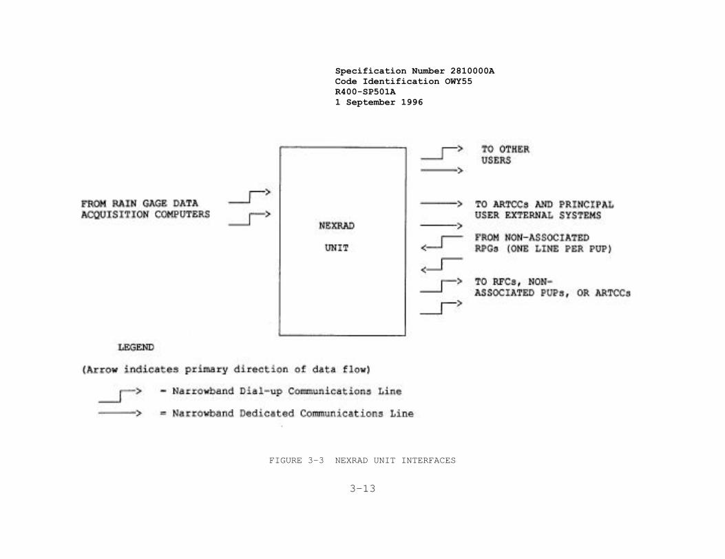
Specification Number 2810000ACode Identification OWY55 R400-SP501A 1 September 1996
3-13
FIGURE 3-3 NEXRAD UNIT INTERFACES

3-14
TABLE 3-1 NEXRAD PRINCIPAL USER ORGANIZATION OVERVIEW
FACILITY RELEVANT RESPONSIBILITY NEED FOR/USE OF NEXRAD INFORMATION
NWS• NMC Issue weather analysis and forecast
guidanceOverview information for generation ofradar summary products; detailedrainfall information; and highresolution data for mesoscale models.
• NSSFC Issue severe convective storm andtornado watches
Low resolution information in stormareas.
• RCs Issue hurricane wathces and warnings Low resolution information inhurricane areas.
• RFCs Derive flood forecasts. High resolutionarea/precipitationestimates covering river basins.
• WSFOs/WSOs Issue severe weather, flood, and flashflood warnings for local area.
High resolution information onhazardous weather in or approachinglocal area.
DOD• BWSs Issue weather warnings and advisories
for AF base area.High resolution information onhazardous weather in or approachingbase area.
• AFGWC Issue weather warnings and advisorieswhere no BWS operating.
High resolution information onhazardous weather where no BWSoperating; Low resolution overviewinformation elsewhere.
• NOCDs Relay weather warnings and advisoriesin Navy base/station area.
High resolution information onhazardous weather in or approachingbase area
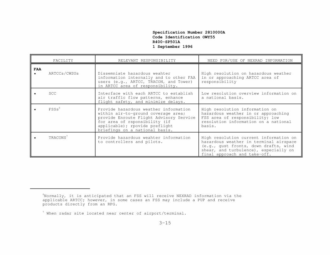
Specification Number 2810000ACode Identification OWY55 R400-SP501A 1 September 1996
FACILITY RELEVANT RESPONSIBILITY NEED FOR/USE OF NEXRAD INFORMATION
6Normally, it is anticipated that an FSS will receive NEXRAD information via the applicable ARTCC; however, in some cases an FSS may include a PUP and receive products directly from an RPG.
7 When radar site located near center of airport/terminal.
3-15
FAA• ARTCCs/CWSUs Dissemniate hazardous weahter
information internally and to other FAAusers (e.g., ARTCC, TRACON, and Tower)in ARTCC area of responsibility.
High resolution on hazardous weatherin or approaching ARTCC area ofresponsibility
• SCC Interface with each ARTCC to establishair traffic flow patterns, enhanceflight safety, and minimize delays.
Low resolution overview information ona national basis.
• FSSs6 Provide hazardous weather informationwithin air-to-ground coverage area;provide Enroute Flight Advisory Servicefor area of rsponsibility (ifapplicable); rpovide preflightbriefings on a national basis.
High resolution information onhazardous weather in or approachingFSS area of responsibility; lowresolution information on a nationalbasis.
• TRACONS7 Provide hazardous weahter informationto controllers and pilots.
High resolution current information onhazardous weather in terminal airspace(e.g., gust fronts, down drafts, windshear, and turbulence), especially onfinal approach and take-off.
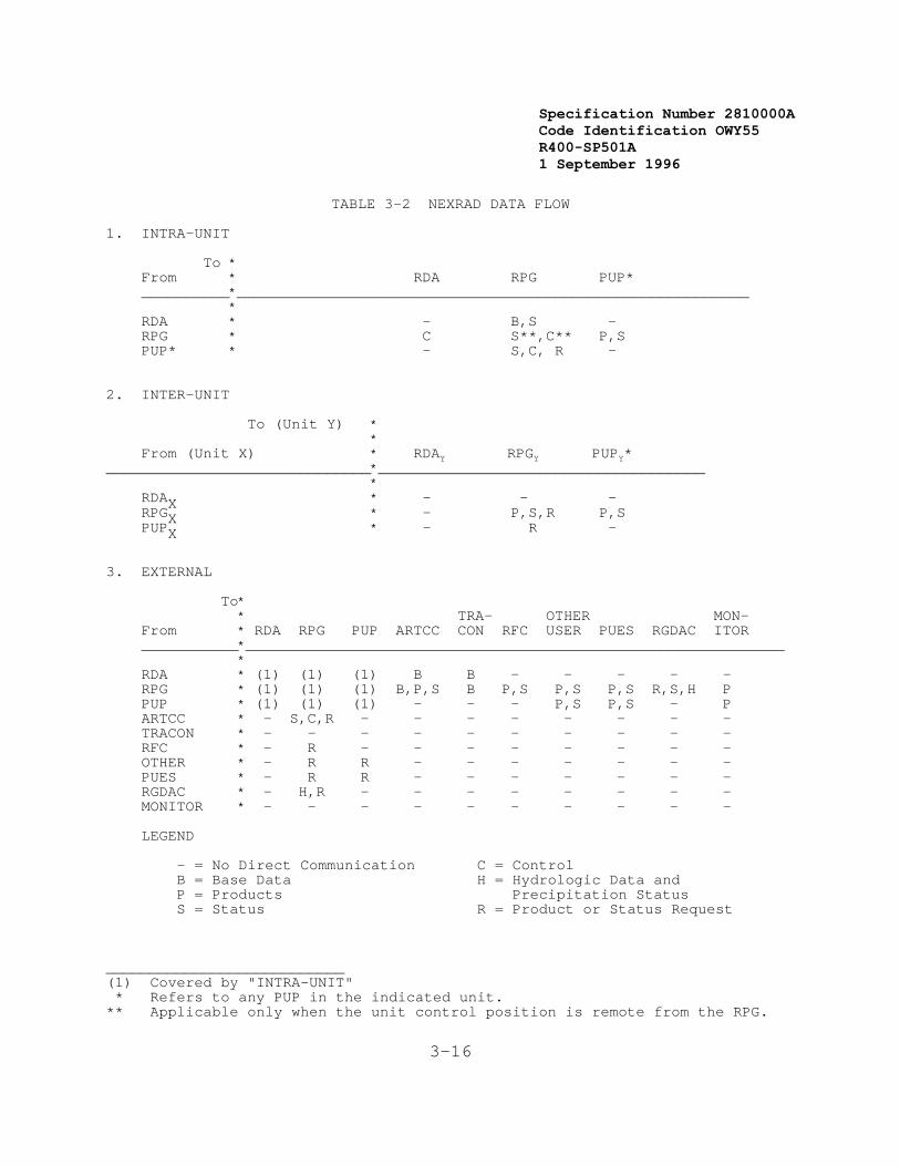
Specification Number 2810000ACode Identification OWY55 R400-SP501A 1 September 1996
3-16
TABLE 3-2 NEXRAD DATA FLOW
1. INTRA-UNIT To * From * RDA RPG PUP* __________*__________________________________________________________ * RDA * - B,S - RPG * C S**,C** P,S PUP* * - S,C, R -
2. INTER-UNIT To (Unit Y) * * From (Unit X) * RDAY RPGY PUPY* ______________________________*_____________________________________ * RDAX * - - - RPGX * - P,S,R P,S PUPX * - R -
3. EXTERNAL To* * TRA- OTHER MON- From * RDA RPG PUP ARTCC CON RFC USER PUES RGDAC ITOR ___________*_____________________________________________________________ * RDA * (1) (1) (1) B B - - - - - RPG * (1) (1) (1) B,P,S B P,S P,S P,S R,S,H P PUP * (1) (1) (1) - - - P,S P,S - P ARTCC * - S,C,R - - - - - - - - TRACON * - - - - - - - - - - RFC * - R - - - - - - - - OTHER * - R R - - - - - - - PUES * - R R - - - - - - - RGDAC * - H,R - - - - - - - - MONITOR * - - - - - - - - - - LEGEND
- = No Direct Communication C = Control B = Base Data H = Hydrologic Data and P = Products Precipitation Status S = Status R = Product or Status Request
___________________________(1) Covered by "INTRA-UNIT" * Refers to any PUP in the indicated unit.** Applicable only when the unit control position is remote from the RPG.
Specification Number 2810000ACode Identification OWY55 R400-SP501A 1 September 1996
3-17
3.1.5 Government Furnished Property (GFP) List
Government furnished algorithms will be supplied . Additional GFP willinclude selected facilities, selected power and air conditioningequipment, narrowband communications, selected voice communications,selected documentation and models, and selected test data.
3.1.6 Operational and Organizational Concepts
The NEXRAD System is expected to provide real-time information on thelocation, intensity, and movement of both routine and hazardous weatherphenomena. These phenomena, although not mutually exclusive, are:precipitation, wind and wind shear, tornadoes, fronts and fine lines,tropical cyclones, mesocyclones, thunderstorms, turbulence, icingconditions, hail, and freezing/melting level.
To meet the minimum objectives of the principal users, the NEXRAD Systemmust acquire, process, and display data in a readily interpretablefashion. Although the NEXRAD System is intended to be a stand-alonesystem, it must also interface with certain existing principal userdisplay and communications systems. This will be accomplished byproviding a standard set of products over a standard communicationsinterface.
The Government will select the geographical locations for all radarsites and principal user sites. Where feasible the equipment needed toperform the RDA and RPG functions of a NEXRAD Unit will be collocatedwith the equipment needed to perform the PUP functions at one of theprincipal user sites. These sites will be in all fifty states, PuertoRico, and at selected overseas locations. In addition to radar sitesand principal user sites, the Government will also select sites in the conterminous United States for maintenance, training, and continuing R&Dactivities.
3.2 System Characteristics
The system shall meet the performance, physical, reliability,maintainability, availability, environmental, and transportabilityrequirements specified in the following sections.
3.2.1 Performance Characteristics
The system shall meet the performance requirements specified in thefollowing sections.
3.2.1.1 NEXRAD Unit Full Load
The NEXRAD Unit full load requirements of the Radar Data Acquisition,Radar Product Generation, Principal User Processing, and Communicationsfunctional areas are defined in this section. The full load defines thetotal number of functions and activities to be performed concurrentlywithin each functional area while meeting all required response time andthroughput requirements (Sections 3.2.1.3 and 3.2.1.4) without loss ofany data or messages.
The NEXRAD Unit full load requirements are the following:
Specification Number 2810000ACode Identification OWY55 R400-SP501A 1 September 1996
3-18
1. [Shall (1)] Perform control and monitoring functions of theRDA functional area.
2. [Shall (2)] Monitor and transmit RDA performance data.
3. [Shall (3)] In a six-minute volume scan time,* provide nineunique elevation angles of base data, from zero degrees to+20 degrees in elevation, from the RDA to the RPG.** (SeeSection 3.7.1.2.1.3)
4. [Shall (4)] Process RDA control commands from the RPG.
5. [Shall (5)] Monitor and control all activities performed bythe RPG.
6. [Shall (6)] Perform concurrent execution within a volumescan time period of algorithms identified in Appendix C forfull load.
7. [Shall (7)] Generate the full load product mix defined inTable E-1.
8. [Shall (8)] Output products from an RPG to eight associatedPUPs, assuming 9600 bps communication circuits. (Theproduct mix for each line shall consist of those full loadproducts that impose the worst case processing load on theNEXRAD Unit.)
9. [Shall (9)] Output products from an RPG to twelvenon-associated PUPs or ARTCCs. (The product mix for eachline shall consist of those full load products that imposethe worst case processing load on the NEXRAD Unit.)
10. [Shall (10)] Accept rain gage input data from 50 rain gages. Data received once per hour from a maximum of one Rain GageData Acquisition Computer (RGDAC).
11. [Shall (11)] Process a mix of peak requests (see Section3.2.1.2) from eight associated PUPs and the operationalposition at the RPG.
12. [Shall (12)] Satisfy all processing requirements defined inSections 3.7.2.1 through 3.7.2.9.
13. [Shall (13)] Display products on each display at the RPGoperational position.
14. [Shall (14)] Control all activities performed by the PUPfunctional area.
15. [Shall (15)] Consistent with the communications limitationsof Table 3-9, receive all products at each PUP from itsassociated RPG. (The product mix shall consist of thosefull load products that impose the worst case processingload on the NEXRAD Unit.)

Specification Number 2810000ACode Identification OWY55 R400-SP501A 1 September 1996
3-19
16. [Shall (16)] Receive products at each PUP from onenon-associated RPG. (The product mix shall consist of thosefull load products that impose the worst case processingload on the PUP.)
17. [Shall (17)] Display products on each display at a PUP.
18. [Shall (18)] Satisfy all processing requirements defined inSection 3.7.3.
19. [Shall (19)] Process a mix of product requests from twelvenon-associated PUPs. (The product mix shall consist ofthose full load products that impose the worst caseprocessing load on the NEXRAD Unit.)
20. [Shall (20)] Output product(s) to four other userinterfaces. (The product mix for each line shall consist ofthose full load products that impose the worst caseprocessing load on the NEXRAD Unit.)
21. [Shall (21)] Consistent with the communications limitationsof Table 3-9, output products from the RPG to four principaluser external systems. (The product mix shall consist ofthose full load products that impose the worst caseprocessing load on the NEXRAD Unit.)
22. [Shall (22)] Output products from a PUP to one principaluser external system. (The product mix shall consist ofthose full load products that impose the worst caseprocessing load on the PUP.)
23. [Shall (23)] Provide the full load archiving as shown inTable E-1.
3.2.1.2 Peak Request Rates
For testing purposes, The full load peak request rates shall (1) bebased on the request types of Table 3-3. The RPG shall (2) handle up to3 product requests (2 existing products and 1 product requiringgeneration) per second. Each operational position shall (3) generate 1display request per second. The requests shall (4) be capable of beingrepeated at a frequency consistent with the response times in Table3-4.
The peak request rate mix of request types is defined as that selectionwhich causes the greatest processing load on the NEXRAD Unit. Therequests shall (5) be capable of being repeated every second if theresponse to the request is less than one second; otherwise, a requestshall (6) be repeated at a frequency consistent with the response timerequired for the results of the request type.
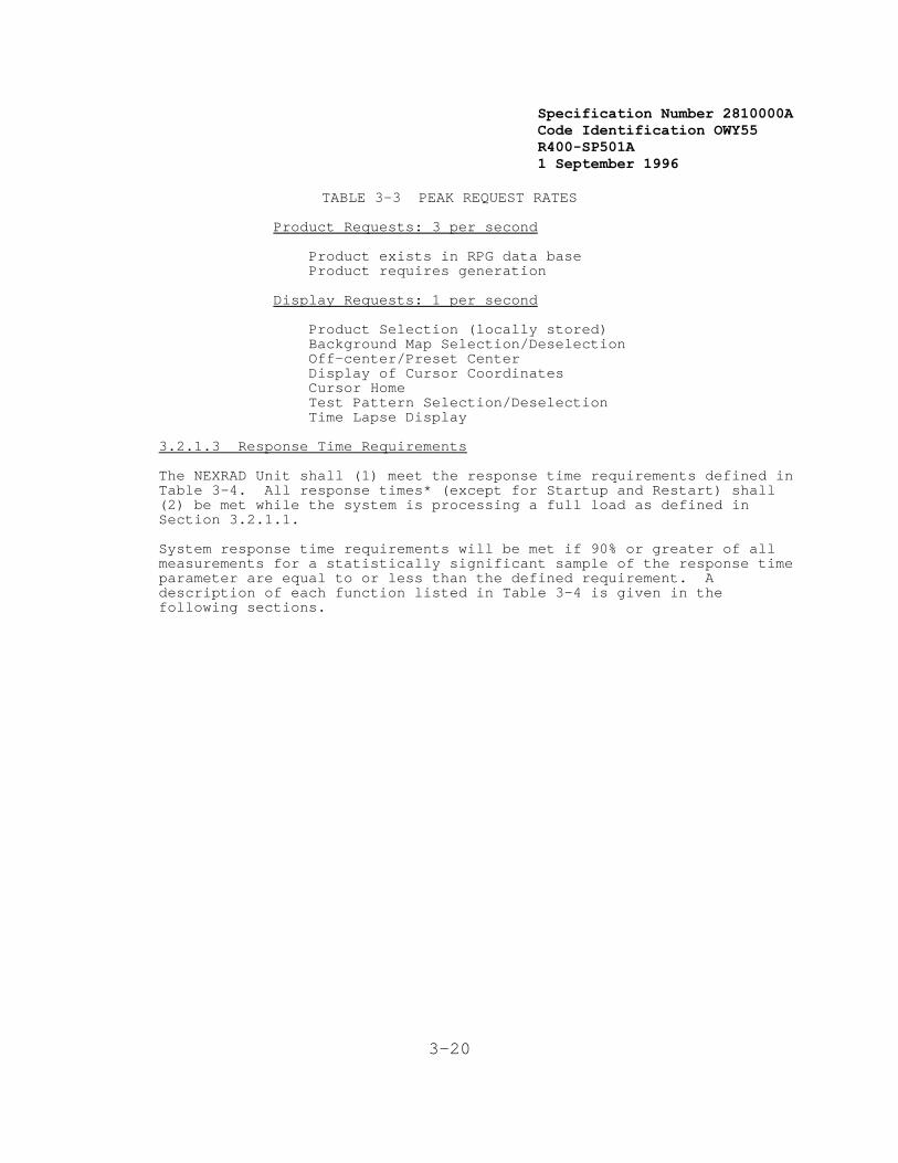
Specification Number 2810000ACode Identification OWY55 R400-SP501A 1 September 1996
3-20
TABLE 3-3 PEAK REQUEST RATES
Product Requests: 3 per second
Product exists in RPG data base Product requires generation
Display Requests: 1 per second
Product Selection (locally stored) Background Map Selection/Deselection Off-center/Preset Center Display of Cursor Coordinates Cursor Home Test Pattern Selection/Deselection Time Lapse Display
3.2.1.3 Response Time Requirements
The NEXRAD Unit shall (1) meet the response time requirements defined inTable 3-4. All response times* (except for Startup and Restart) shall(2) be met while the system is processing a full load as defined inSection 3.2.1.1.
System response time requirements will be met if 90% or greater of allmeasurements for a statistically significant sample of the response timeparameter are equal to or less than the defined requirement. Adescription of each function listed in Table 3-4 is given in thefollowing sections.
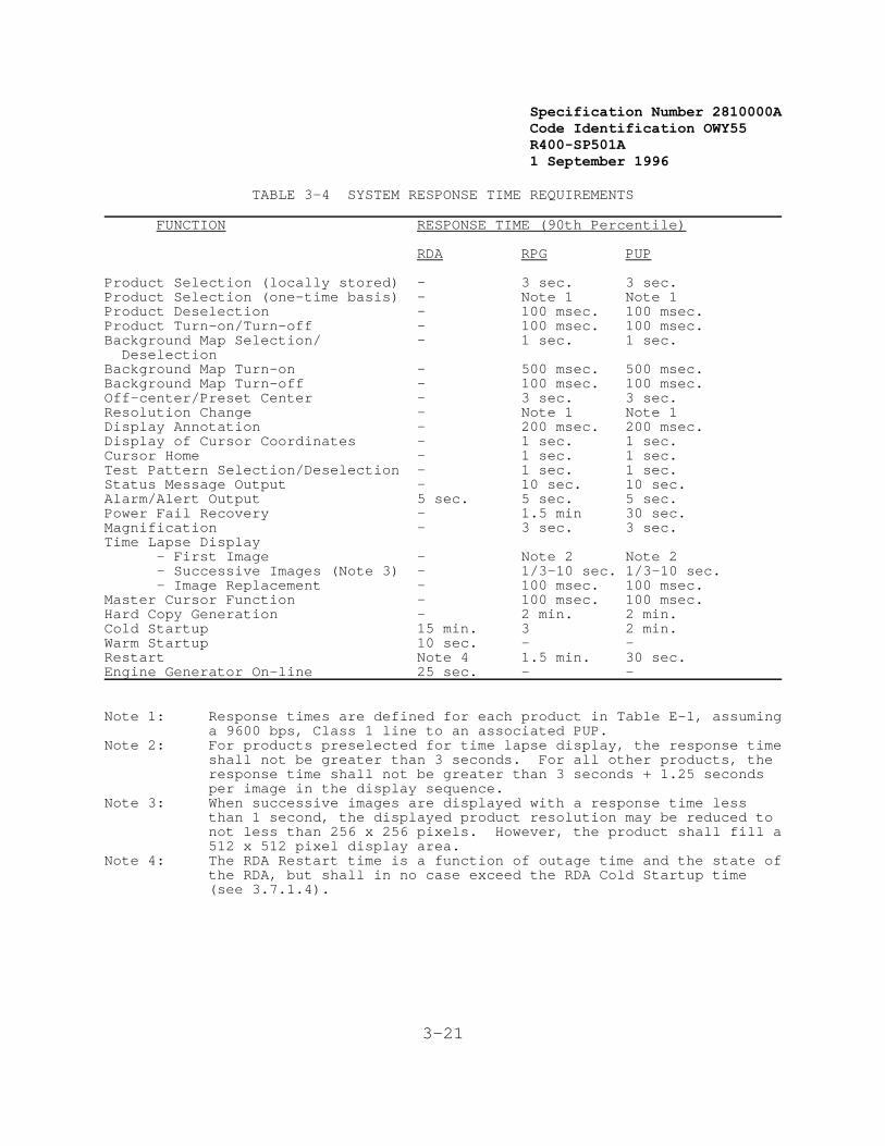
Specification Number 2810000ACode Identification OWY55 R400-SP501A 1 September 1996
3-21
TABLE 3-4 SYSTEM RESPONSE TIME REQUIREMENTS
FUNCTION RESPONSE TIME (90th Percentile)
RDA RPG PUP
Product Selection (locally stored) - 3 sec. 3 sec.Product Selection (one-time basis) - Note 1 Note 1Product Deselection - 100 msec. 100 msec.Product Turn-on/Turn-off - 100 msec. 100 msec.Background Map Selection/ - 1 sec. 1 sec. DeselectionBackground Map Turn-on - 500 msec. 500 msec.Background Map Turn-off - 100 msec. 100 msec.Off-center/Preset Center - 3 sec. 3 sec.Resolution Change - Note 1 Note 1Display Annotation - 200 msec. 200 msec.Display of Cursor Coordinates - 1 sec. 1 sec.Cursor Home - 1 sec. 1 sec.Test Pattern Selection/Deselection - 1 sec. 1 sec.Status Message Output - 10 sec. 10 sec.Alarm/Alert Output 5 sec. 5 sec. 5 sec.Power Fail Recovery - 1.5 min 30 sec. Magnification - 3 sec. 3 sec.Time Lapse Display
- First Image - Note 2 Note 2- Successive Images (Note 3) - 1/3-10 sec. 1/3-10 sec.- Image Replacement - 100 msec. 100 msec.
Master Cursor Function - 100 msec. 100 msec.Hard Copy Generation - 2 min. 2 min.Cold Startup 15 min. 3 2 min.Warm Startup 10 sec. - -Restart Note 4 1.5 min. 30 sec.Engine Generator On-line 25 sec. - -
Note 1: Response times are defined for each product in Table E-1, assuminga 9600 bps, Class 1 line to an associated PUP.
Note 2: For products preselected for time lapse display, the response timeshall not be greater than 3 seconds. For all other products, theresponse time shall not be greater than 3 seconds + 1.25 secondsper image in the display sequence.
Note 3: When successive images are displayed with a response time lessthan 1 second, the displayed product resolution may be reduced tonot less than 256 x 256 pixels. However, the product shall fill a512 x 512 pixel display area.
Note 4: The RDA Restart time is a function of outage time and the state ofthe RDA, but shall in no case exceed the RDA Cold Startup time(see 3.7.1.4).
Specification Number 2810000ACode Identification OWY55 R400-SP501A 1 September 1996
3-22
3.2.1.3.1 Product and Background Map Display
Products and background maps selected for display shall (1) becompletely displayed within the response time required. Products andbackground maps deselected shall (2) be deleted from the display withinthe response time required. In the case of products, data displayedshall (3) be the last completed update of that product.
Product data and background maps shall (4) be capable of being turned onand turned off within the response times defined.
3.2.1.3.2 Off-Center/Preset Center
The off-center function shall (1) provide the capability to reorient thedisplay of products relative to the display center within the systemgeographic boundaries. The current cursor location on the display shall(2) become the new center position when an off-center action isrequested. The preset center action shall (3) provide the capability toreorient the display to a predefined center position (adaptation data*). Map data shall (4) be adjusted to correctly overlay the requested image. An off-center or preset center request action shall (5) be completedwithin the response time required. During the processing time requiredto accomplish the action, the display image may be static or whollyblanked for up to the total period required to complete the action butnot longer than the response time requirement. If a second off-centeror preset center action is requested prior to completion of the firstoff-center or preset center request, then processing of the firstrequest shall (6) cease and the second request shall (7) be processed.
3.2.1.3.3 Resolution Change
The resolution change function shall (1) include the capability tochange both the geographic coverage of a displayed product and thegeographic resolution of the data for those products having multipleresolutions. Resolution change may be accomplished through theselection of other available resolutions of the displayed product fromthe RPG. When a resolution change request is made, the current displaycenter coordinates shall (2) be used for the center of the requestedimage. Background maps shall (3) be adjusted to correctly over-lay therequested image. A resolution change shall (4) be completed within theresponse time required. During the processing time required toaccomplish the action the display image may be static for up to thetotal period required to complete the action, but not longer than theresponse time requirement. Following initiation of a resolution changerequest, a positive response shall (5) be provided to the operator thatthe request has been received and is being processed. If a secondresolution change action is requested prior to the completion of thefirst resolution change action, then processing of the first requestshall (6) be stopped and the second request shall (7) be processed.
3.2.1.3.4 Display Annotation
The response to any operator input action which causes insertion ordeletion of data on a display shall (1) be completed within the responsetime required. The response time shall (2) include the time to update apreview area and the preview area cursor symbol, or the time to

Specification Number 2810000ACode Identification OWY55 R400-SP501A 1 September 1996
3-23
annotate a display area selected by a cursor.
3.2.1.3.5 Display of Cursor Coordinates
The present value of the master cursor coordinates shall (1) be updatedwithin the response time required, after the cursor has stopped. Thesevalues shall (2) always be displayed and consist of range/azimuth/heightor latitude/longitude/height as selected by the operator. The value forheight is not required for composite products.
3.2.1.3.6 Cursor Home
The cursor symbol shall (1) be positioned at an adaptation controlledposition on the display within the response time required, following therequesting action.
3.2.1.3.7 Test Pattern Selection/Deselection
Following the test pattern selection action, the test pattern shall (1)be displayed within the response time required. Following the testpattern deselection action, the operational data displayed prior to thetest pattern selection, including updated data occurring during theperiod the test pattern was displayed, shall (2) be displayed within theresponse time required.
3.2.1.3.8 Status Message Output
Display of status messages at the unit control position, the RPGoperational position, or the PUP operational position shall (1) becompleted within the time indicated in Table 3-4. This time shall (2)be based on the time interval between arrival of a message at thefunctional area and completion of display, or the time interval betweengeneration and display for a message originating within the samefunctional area.
3.2.1.3.9 Alarm/Alert Output
The following alarm/alert response times shall (1) be within the timesindicated in Table 3-4:
1. [Shall (1a)] Time from the detection of an alarm conditionto the activation of a local alarm.
2. [Shall (1b)] Time from the detection of an alarm conditionto the display of an alarm message at the unit controlposition.
3. [Shall (1c)] Time from the detection of an alert conditionto the display of the alert message at the operationalpositions.
All products automatically generated when alert criteria are met shall(2) meet the appropriate response times for one-time product requests asshown in Table E-1.
3.2.1.3.10 Power Fail Recovery
Specification Number 2810000ACode Identification OWY55 R400-SP501A 1 September 1996
3-24
When normal power levels have returned following a power interruption,the NEXRAD Unit shall (1) automatically resume normal operation, allfunctions shall (2) be available to users, and all previously displayedand stored data shall (3) be displayed within the response timerequired. Specifically, the RDA and RPG shall (4) retain all acquireddata necessary for full load operation for any number of outages per 24hour period with no single outage exceeding 15 seconds and the totalduration of outages for a 24 hour period not exceeding five minutes withthe interval between outages not less than 0.1 second. All unitadaptation and control information shall (5) be stored in such a mannerthat required response times can be met for a restart up to at least onehour after power interruption, and that all operational positions can bereturned to the state existing immediately prior to the outage.
3.2.1.3.11 Magnification
The magnification function shall (1) provide the capability to expandthe currently displayed product data using the current display centerpoint or the cursor position. The magnification function shall (2)provide for a display of data having the same resolution as the datadisplayed before selection of the magnification function. Themagnification function shall (3) not be required when a display is usedin a 1/4 screen mode.
Data selected for display, using the magnification function shall (4) be completely displayed within the response time required. During theprocessing time required to accomplish the action, the display image maybe static or wholly blanked for up to the total period required tocomplete the action but not longer than the response time requirement.If a second magnification action is requested from the same operationalposition during the period required to complete the first action, thenthe final display shall (5) reflect the second action and the responsetime shall (6) be measured from the completion of the second requestaction.
3.2.1.3.12 Time Lapse Display
A time lapse display request shall (1) result in a sequence of images ofa specific product being presented on the display, as defined in detailin Section 3.7.3.3.5. It shall (2) be possible to time lapse anysequence of base or derived products currently in the local data basewhile meeting the response times shown in Table 3-4. The last image inthe sequence shall (3) remain on the display and be updated as part ofthe normal operational product updating sequence.
Each RPG or PUP operational position shall (4) have the capability topreselect up to three products for future time lapse display.
3.2.1.3.13 Master Cursor Function
Operational positions shall (1) have the capability of defining thecursors as being linked such that each cursor is positioned in the samegeographic position. The cursor on either of the graphic displays shall(2) be capable of being designated by operator action as the mastercursor, with the cursor(s) on the other display being slaved. The

Specification Number 2810000ACode Identification OWY55 R400-SP501A 1 September 1996
8 Defined in Appendix B
3-25
update time for positioning each slave cursor shall (3) be within theresponse time required. When a display is used in the 1/4 screen mode,there is no requirement for the capability to designate one of its fourcursors as the master cursor.
3.2.1.3.14 Hard Copy Generation
The time from the request for hard copy output until it is availableshall (1) be within the response time required.
3.2.1.3.15 Startup/Restart
The time from the initiation of a startup or restart action until itscompletion shall (1) be within the response time required.
3.2.1.3.16 Engine Generator On-line
In the event of primary power failure or manual selection of backuppower, the backup engine generator shall (1) become operational andon-line within the response time required.
3.2.1.4 Unit Throughput
Products generated on a routine basis by the RPG shall (1) be displayedat operational positions at the RPG and PUP within the throughput time*requirements defined in Table E-1. All throughput time measurements shall (2) be taken while the NEXRAD Unit is performing under a full loadcondition. NEXRAD Unit throughput time requirements will be met if 90%or greater of all measurements for a statistically significant sample ofthe throughput parameter are equal to or less than the definedrequirement.
3.2.1.5 Configuration
Table 3-5 defines [shall (1)] the as-delivered minimum operational,full-load test, and maximum operational configuration requirements forNEXRAD Units, without considering expandability requirements. Functionally, the following configurations shall (2) be possible withoutmodification (facilities excluded) of the NEXRAD equipment:
1. [Shall (2a)] Collocated8 RDA, RPG, PUP (Operational positionnot located in RDA/RPG equipment area)
2. [Shall (2b)] Separate RDA; collocated RPG/PUP
3. [Shall (2c)] Collocated RDA/RPG; separate PUP
4. [Shall (2d)] Redundant, collocated RDA/RPG (3.2.1.5.1);separate PUP
5. [Shall (2e)] Redundant separate RDA (3.2.1.5.2); CollocatedRPG/PUP

Specification Number 2810000ACode Identification OWY55 R400-SP501A 1 September 1996
3-26
3.2.1.5.1 FAA Redundant Configuration
A capability for a collocated RDA/RPG (availability B) in a fullyredundant configuration shall (1) be provided. All RDA and RPGfunctional area equipment including any wideband and narrowbandcommunications, but excluding the antenna, pedestal, tower, and backuppower generator shall (2) be redundant. The point for recombining theredundant channels shall (3) be the output of the narrowbandcommunications ports. A single environmentally controlled area shall(4) be provided to house both redundant channels. The equipment shall(5) be arranged to facilitate convenient and efficient maintenance.
For FAA Redundant Systems, all UCP equipment shall (5a) be redundant toenable switching control of the NEXRAD site between two separatepositions. The Redundant UCP shall (5b) be configured in such a mannerthat only one UCP is in control at any given time. All functionsperformed by one UCP shall (5c) be fully performed by the other one. Mechanical switching shall (5d) be provided to allow the operator todirectly connect the UCP terminal to either RPG computer, as well as toswitch full control of the system to the redundant UCP. The UCPfunctions of both channels shall (6) be combined into one and madeavailable at a single console for full status reporting, alarms, andcontrol. A selection capability shall (7) be provided at the UCP tobring either channel to standby (controlled shutdown state, 3.7.2.5.5)or full operation, regardless of the state of the other channel.
The back-up power generator and the air conditioning equipment shall (8)be sized and configured to support one channel at full operation andonly the filament voltage applied to the klystron of the redundantchannel.
3.2.1.5.2 NWS Redundant Configuration
A capability for a configuration comprised of a redundant RDA(availability B) and a single-channel RPG which is collocated with anassociated PUP or RPGOP shall (1) be provided. All RDA functional areaequipment, but excluding wideband communications, antenna, pedestal,tower, and backup power generator, shall (2) be redundant. The pointfor recombining the redundant channels shall (3) be the output of thewideband communications ports. A single, environmentally controlledarea shall (4) be provided to house both redundant RDA channels. Theequipment shall (5) be arranged to facilitate convenient and efficientmaintenance.
The UCP shall (6) be capable of full status reporting, alarms, andcontrol of both RDA channels. A selection capability shall (7) beprovided at the Remote RDA maintenance terminal to bring either channelto full-off, standby (controlled shutdown state, 3.7.2.5.5) or fulloperation, regardless of the state of the other channel. A narrowbandcommunications link with a defined protocol may be used for thispurpose.
The back-up power generator and the air conditioning equipment shall (8)be sized and configured to support this configuration.

Specification Number 2810000ACode Identification OWY55 R400-SP501A 1 September 1996
3-27
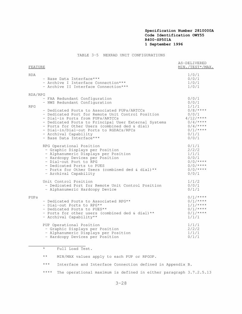
Specification Number 2810000ACode Identification OWY55 R400-SP501A 1 September 1996
3-28
TABLE 3-5 NEXRAD UNIT CONFIGURATIONS
AS-DELIVERED FEATURE MIN./TEST*/MAX.
RDA 1/0/1 - Base Data Interface*** 0/0/1
- Archive I Interface Connection*** 1/0/1 - Archive II Interface Connection*** 1/0/1
RDA/RPG- FAA Redundant Configuration 0/0/1 - NWS Redundant Configuration 0/0/1
RPG 1/1/1 - Dedicated Ports to Associated PUPs/ARTCCs 0/8/**** - Dedicated Port for Remote Unit Control Position 0/0/1
- Dial-in Ports from PUPs/ARTCCs 4/12/**** - Dedicated Ports to Principal User External Systems 0/4/**** - Ports for Other Users (combined ded & dial) 0/4/**** - Dial-in/Dial-out Ports to RGDACs/RFCs 0/1/**** - Archival Capability 0/1/1 - Base Data Interface*** 0/0/1
RPG Operational Position 0/1/1 - Graphic Displays per Position 2/2/2 - Alphanumeric Displays per Position 1/1/1 - Hardcopy Devices per Position 0/0/1 - Dial-out Port to RPG 0/0/**** - Dedicated Ports to PUES 0/0/**** - Ports for Other Users (combined ded & dial)** 0/0/**** - Archival Capability 0/0/1
Unit Control Position 1/1/2 - Dedicated Port for Remote Unit Control Position 0/0/1 - Alphanumeric Hardcopy Device 0/1/1
PUPs 0/1/**** - Dedicated Ports to Associated RPG** 0/1/**** - Dial-out Ports to RPG** 1/1/**** - Dedicated Ports to PUES** 0/1/**** - Ports for other users (combined ded & dial)** 0/1/**** - Archival Capability** 1/1/1
PUP Operational Position 1/1/1 - Graphic Displays per Position 2/2/2 - Alphanumeric Displays per Position 1/1/1 - Hardcopy Devices per Position 0/1/1
________________________* Full Load Test.
** MIN/MAX values apply to each PUP or RPGOP.
*** Interface and Interface Connection defined in Appendix B.
**** The operational maximum is defined in either paragraph 3.7.2.5.13

Specification Number 2810000ACode Identification OWY55 R400-SP501A 1 September 1996
3-29
or 3.7.3.6.6.3.2.1.6 Useful Life
The NEXRAD System shall (1) be designed for continuous operation andhave a useful life of 20 years.
3.2.1.7 Data Processing Reserve
The equipment performing the RPG functions shall (1) have a processingreserve such that when processing the full load requirements (defined inSection 3.2.1.1) the utilization of each of the processing, global mainmemory, and direct access mass storage functions shall (1) not exceed60%, averaged over a volume scan time period.
3.2.1.8 Expandability
NEXRAD Units shall (1) be incrementally expandable by fieldmodification. The expansion capability* is in reference to the NEXRADUnit equipment to meet the NEXRAD Unit full load, as defined in 3.2.1.1,including the reserve as defined in 3.2.1.7.
The RPG functional area shall (2) be expandable to the following:
1. Processing Capacity: 3 times
2. Global Main Memory: 3 times
3. Direct Access Mass Storage Devices: 3 times
4. Archival Storage Devices: 2 times
5. Narrowband Ports as defined in 3.7.2.5.13
6. RPGOP: Same as PUP Expandability Items 1, 2, 3, 4, and 5defined below.
The PUP functional area shall (3) be expandable to the following:
1. Processing Capacity: 2 times
2. Global Main Memory: 2 times
3. Direct Access Mass Storage Devices: 2 times
4. Archival Storage Devices: 2 times
5. Narrowband Ports: as defined in 3.7.3.6.6.
3.2.2 Physical Characteristics
Section 3.7.5 further defines physical characteristic limitationsconsistent with existing access capabilities.
3.2.3 Reliability
This section defines the hardware reliability requirements for the

Specification Number 2810000ACode Identification OWY55 R400-SP501A 1 September 1996
9 Defined in Appendix B
10 Defined in Appendix B
11 Defined in Appendix B Under Availability
12 Defined in Appendix B
13 Defined in Appendix B
3-30
NEXRAD System.
3.2.3.1 Hardware Reliability
This section defines requirements for Mean Time Between Failures**(MTBF), Mean Time Between Visits* (MTBV), and Mean Time BetweenMaintenance Actions** (MTBMA).
The MTBF of each independent hardware Configuration Item* (CI) shall (1)be sufficient to enable each of the inherent Availability (A(i))requirements of Section 3.2.5 to be satisfied.
The MTBMA of each independent hardware configuration item (CI) shall (2)be sufficient to enable each of the achieved availability (A(a))requirements of Section 3.2.5 to be satisfied.
For NEXRAD Units required to meet the availability requirement C(defined in Section 3.2.5), the MTBV shall (3) not be less than 200hours for a dual channel.9 The Government will specify which NEXRADUnits must meet availability requirements B and C.
3.2.4 Maintainability
Maintainability is defined in terms of a NEXRAD Unit Mean Time To Repair(MTTR),10 Mean Active Maintenance Down Time (M),11 and Maximum Downtime(MDT).12 These requirements are stated for field replacement of LineReplaceable Units (LRUs).13
The NEXRAD Unit MTTR shall (1) be less than or equal to one-half hour.
The MDT requirements are defined in terms of the RDA, RPG, PUP, andCommunications functional areas defined in Figure 3-4. The specific MDTrequirements are as follows:
Functional Area (Figure 3-4) MDT
RDA 2 HoursRPG 1 HourPUP 1 HourCommunications 1 Hour
3.2.5 Availability
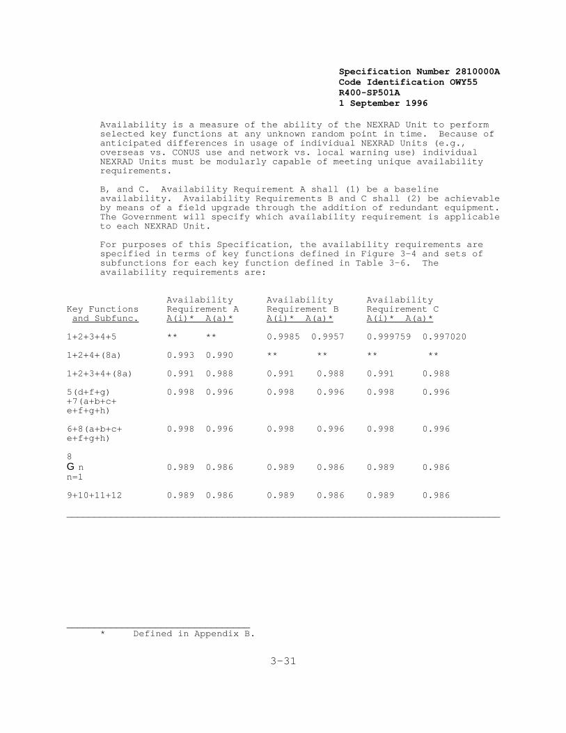
Specification Number 2810000ACode Identification OWY55 R400-SP501A 1 September 1996
3-31
Availability is a measure of the ability of the NEXRAD Unit to performselected key functions at any unknown random point in time. Because ofanticipated differences in usage of individual NEXRAD Units (e.g.,overseas vs. CONUS use and network vs. local warning use) individualNEXRAD Units must be modularly capable of meeting unique availabilityrequirements.
B, and C. Availability Requirement A shall (1) be a baselineavailability. Availability Requirements B and C shall (2) be achievableby means of a field upgrade through the addition of redundant equipment. The Government will specify which availability requirement is applicableto each NEXRAD Unit.
For purposes of this Specification, the availability requirements arespecified in terms of key functions defined in Figure 3-4 and sets ofsubfunctions for each key function defined in Table 3-6. Theavailability requirements are:
Availability Availability Availability
Key Functions Requirement A Requirement B Requirement C and Subfunc. A(i)* A(a)* A(i)* A(a)* A(i)* A(a)* 1+2+3+4+5 ** ** 0.9985 0.9957 0.999759 0.997020
1+2+4+(8a) 0.993 0.990 ** ** ** **
1+2+3+4+(8a) 0.991 0.988 0.991 0.988 0.991 0.988
5(d+f+g) 0.998 0.996 0.998 0.996 0.998 0.996+7(a+b+c+e+f+g+h)
6+8(a+b+c+ 0.998 0.996 0.998 0.996 0.998 0.996e+f+g+h)
8G n 0.989 0.986 0.989 0.986 0.989 0.986n=1
9+10+11+12 0.989 0.986 0.989 0.986 0.989 0.986
______________________________________________________________________________
_________________________________* Defined in Appendix B.
Specification Number 2810000ACode Identification OWY55 R400-SP501A 1 September 1996
3-32
** No specific A(i) or A(a) requirement specified for this functional combination.
3.2.6 Environmental Conditions
The NEXRAD System shall (1) be capable of operating in and withstandingthe environmental conditions specified in the following sections. Operating criteria define the conditions under which the system shall(2) operate and meet all performance specifications. Nonoperatingcriteria, including those for transportation and storage, defineconditions which the system shall (3) withstand without damage.
These unique requirements are identified as Availability Requirements A,B, and C. Availability Requirement A shall be a baseline availability. Availability Requirements B and C shall be achievable by means of afield upgrade through the addition of redundant equipment. TheGovernment will specify which availability requirement is applicable toeach NEXRAD Unit.
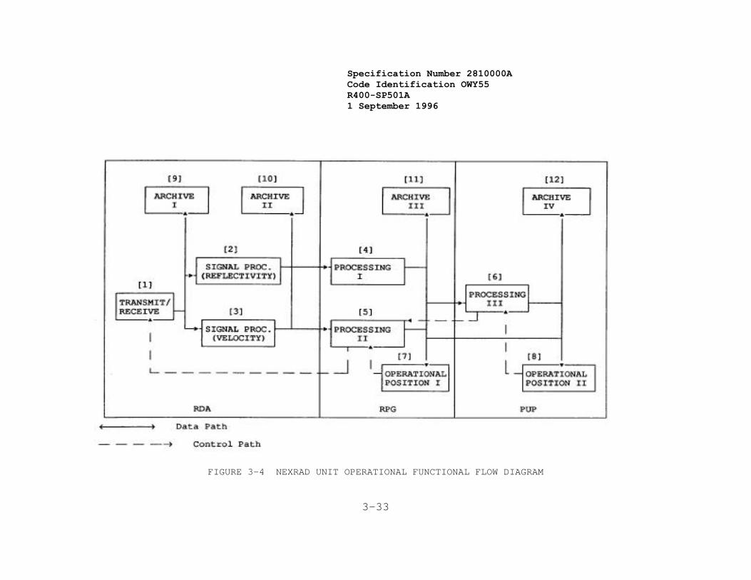
Specification Number 2810000ACode Identification OWY55 R400-SP501A 1 September 1996
3-33
FIGURE 3-4 NEXRAD UNIT OPERATIONAL FUNCTIONAL FLOW DIAGRAM
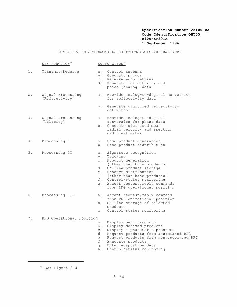
Specification Number 2810000ACode Identification OWY55 R400-SP501A 1 September 1996
14 See Figure 3-4
3-34
TABLE 3-6 KEY OPERATIONAL FUNCTIONS AND SUBFUNCTIONS
KEY FUNCTION14 SUBFUNCTIONS
1. Transmit/Receive a. Control antennab. Generate pulsesc. Receive echo returnsd. Separate reflectivity and phase (analog) data
2. Signal Processing a. Provide analog-to-digital conversion(Reflectivity) for reflectivity data
b. Generate digitized reflectivity estimates
3. Signal Processing a. Provide analog-to-digital(Velocity) conversion for phase data
b. Generate digitized mean radial velocity and spectrum width estimates
4. Processing I a. Base product generationb. Base product distribution
5. Processing II a. Signature recognition b. Trackingc. Product generation (other than base products)d. On-line product storagee. Product distribution (other than base products)f. Control/status monitoringg. Accept request/reply commands from RPG operational position
6. Processing III a. Accept request/reply command from PUP operational positionb. On-line storage of selected productsc. Control/status monitoring
7. RPG Operational Position a. Display base productsb. Display derived productsc. Display alphanumeric productsd. Request products from associated RPGe. Request products from nonassociated RPGf. Annotate productsg. Enter adaptation datah. Control/status monitoring

Specification Number 2810000ACode Identification OWY55 R400-SP501A 1 September 1996
15 See Figure 3-4
3-35
TABLE 3-6(concluded)
KEY FUNCTION15 SUBFUNCTIONS
8. PUP Operational Position a. Display locally stored base productsb. Display locally stored derived productsc. Display locally stored alphanumeric
productsd. Request products from associated RPGe. Request products from non-associated RPGf. Annotate productsg. Enter adaptation datak. Control/status monitoring
9/10. Archive I/II a. Format data for recording on appropriatemedium
b. Support future connection of appropriaterecording device
11/12. Archive III/IV a. Format data for recordingb. Control recording devicec. Record selected products
______________________________________________________________________________
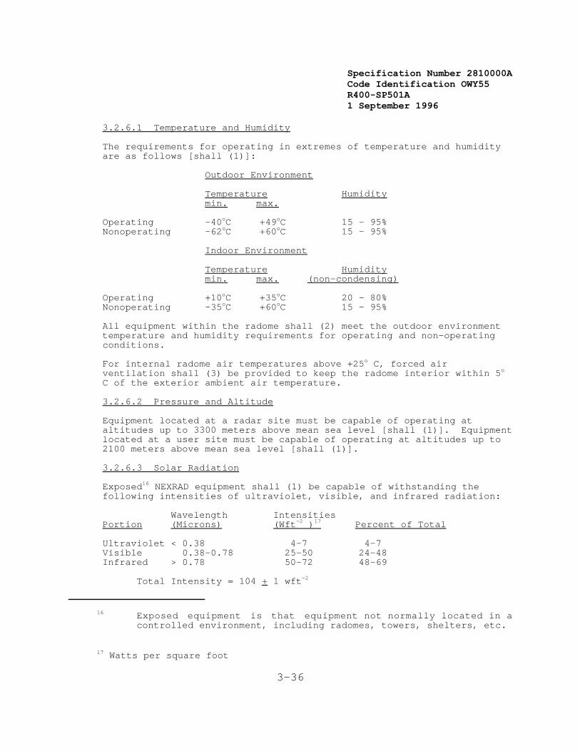
Specification Number 2810000ACode Identification OWY55 R400-SP501A 1 September 1996
16 Exposed equipment is that equipment not normally located in acontrolled environment, including radomes, towers, shelters, etc.
17 Watts per square foot
3-36
3.2.6.1 Temperature and Humidity
The requirements for operating in extremes of temperature and humidityare as follows [shall (1)]:
Outdoor Environment
Temperature Humiditymin. max.
Operating -40oC +49oC 15 - 95% Nonoperating -62oC +60oC 15 - 95%
Indoor Environment
Temperature Humiditymin. max. (non-condensing)
Operating +10oC +35oC 20 - 80%Nonoperating -35oC +60oC 15 - 95%
All equipment within the radome shall (2) meet the outdoor environmenttemperature and humidity requirements for operating and non-operatingconditions.
For internal radome air temperatures above +25o C, forced airventilation shall (3) be provided to keep the radome interior within 5o
C of the exterior ambient air temperature.
3.2.6.2 Pressure and Altitude
Equipment located at a radar site must be capable of operating ataltitudes up to 3300 meters above mean sea level [shall (1)]. Equipmentlocated at a user site must be capable of operating at altitudes up to2100 meters above mean sea level [shall (1)].
3.2.6.3 Solar Radiation
Exposed16 NEXRAD equipment shall (1) be capable of withstanding thefollowing intensities of ultraviolet, visible, and infrared radiation:
Wavelength IntensitiesPortion (Microns) (Wft-2 )17 Percent of Total
Ultraviolet < 0.38 4-7 4-7Visible 0.38-0.78 25-50 24-48Infrared > 0.78 50-72 48-69
Total Intensity = 104 + 1 wft-2
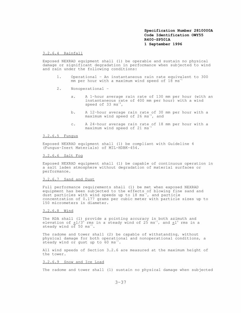
Specification Number 2810000ACode Identification OWY55 R400-SP501A 1 September 1996
3-37
3.2.6.4 Rainfall
Exposed NEXRAD equipment shall (1) be operable and sustain no physicaldamage or significant degradation in performance when subjected to windand rain under the following conditions:
1. Operational - An instantaneous rain rate equivalent to 300mm per hour with a maximum wind speed of 18 ms-1
2. Nonoperational -
a. A 1-hour average rain rate of 130 mm per hour (with aninstantaneous rate of 400 mm per hour) with a windspeed of 33 ms-1,
b. A 12-hour average rain rate of 30 mm per hour with amaximum wind speed of 26 ms-1, and
c. A 24-hour average rain rate of 18 mm per hour with amaximum wind speed of 21 ms-1
3.2.6.5 Fungus
Exposed NEXRAD equipment shall (1) be compliant with Guideline 4(Fungus-Inert Materials) of MIL-HDBK-454.
3.2.6.6 Salt Fog
Exposed NEXRAD equipment shall (1) be capable of continuous operation ina salt laden atmosphere without degradation of material surfaces orperformance.
3.2.6.7 Sand and Dust
Full performance requirements shall (1) be met when exposed NEXRADequipment has been subjected to the effects of blowing fine sand anddust particles with wind speeds up to 18 ms-1, and particleconcentration of 0.177 grams per cubic meter with particle sizes up to150 micrometers in diameter.
3.2.6.8 Wind
The RDA shall (1) provide a pointing accuracy in both azimuth and elevation of +1/3o rms in a steady wind of 25 ms-1, and +1o rms in asteady wind of 50 ms-1.
The radome and tower shall (2) be capable of withstanding, withoutphysical damage for both operational and nonoperational conditions, asteady wind or gust up to 60 ms-1.
All wind speeds of Section 3.2.6 are measured at the maximum height ofthe tower.
3.2.6.9 Snow and Ice Load
The radome and tower shall (1) sustain no physical damage when subjected
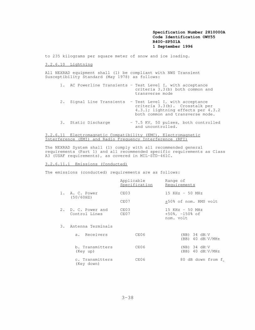
Specification Number 2810000ACode Identification OWY55 R400-SP501A 1 September 1996
3-38
to 235 kilograms per square meter of snow and ice loading.
3.2.6.10 Lightning
All NEXRAD equipment shall (1) be compliant with NWS TransientSusceptibility Standard (May 1978) as follows:
1. AC Powerline Transients - Test Level I, with acceptancecriteria 3.3(b) both common andtransverse mode
2. Signal Line Transients - Test Level I, with acceptancecriteria 3.3(b). Crosstalk per4.3.1; lightning effects per 4.3.2both common and transverse mode.
3. Static Discharge - 7.5 KV, 50 pulses, both controlledand uncontrolled.
3.2.6.11 Electromagnetic Compatibility (EMC), ElectromagneticInterference (EMI) and Radio Frequency Interference (RFI)
The NEXRAD System shall (1) comply with all recommended generalrequirements (Part 1) and all recommended specific requirements as ClassA3 (USAF requirements), as covered in MIL-STD-461C.
3.2.6.11.1 Emissions (Conducted)
The emissions (conducted) requirements are as follows:
Applicable Range ofSpecification Requirements
1. A. C. Power CE03 15 KHz - 50 MHz (50/60HZ) CE07 +50% of nom. RMS volt
2. D. C. Power and CE03 15 KHz - 50 MHz Control Lines CE07 +50%, -150% of
nom. volt
3. Antenna Terminals
a. Receivers CE06 (NB) 34 dB:V(BB) 40 dB:V/MHz
b. Transmitters CE06 (NB) 34 dB:V (Key up) (BB) 40 dB:V/MHz
c. Transmitters CE06 80 dB down from fo (Key down)
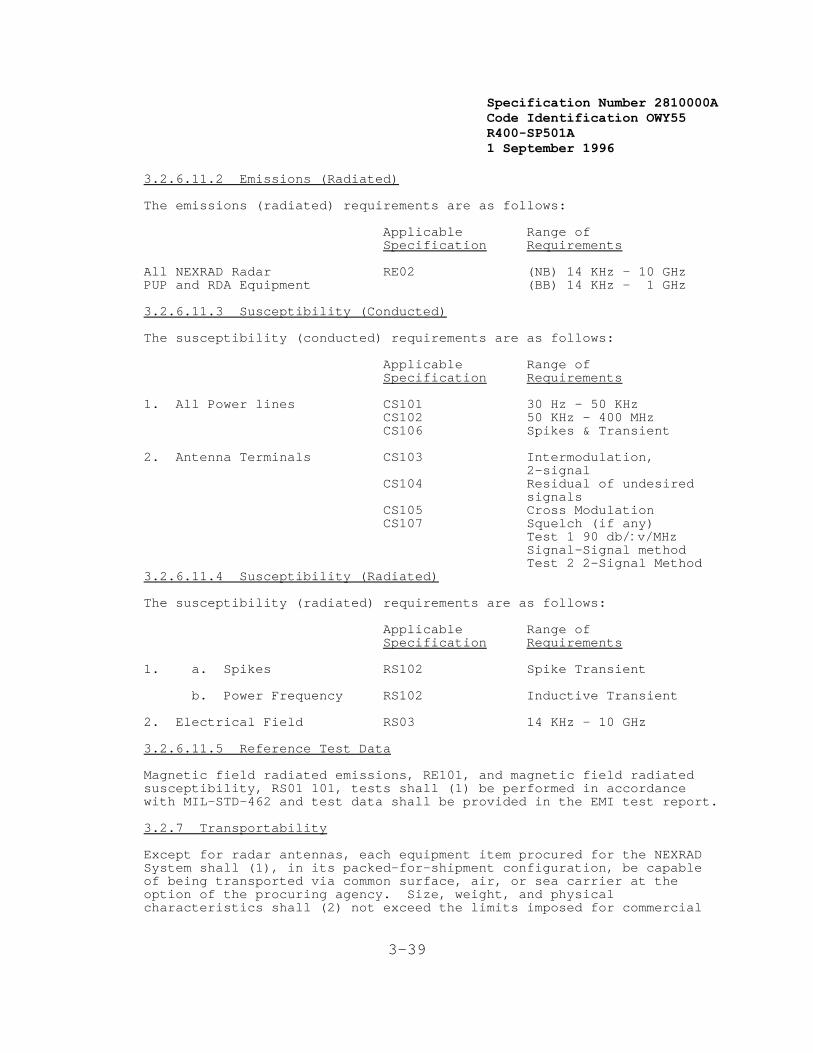
Specification Number 2810000ACode Identification OWY55 R400-SP501A 1 September 1996
3-39
3.2.6.11.2 Emissions (Radiated)
The emissions (radiated) requirements are as follows:
Applicable Range ofSpecification Requirements
All NEXRAD Radar RE02 (NB) 14 KHz - 10 GHzPUP and RDA Equipment (BB) 14 KHz - 1 GHz
3.2.6.11.3 Susceptibility (Conducted)
The susceptibility (conducted) requirements are as follows:
Applicable Range ofSpecification Requirements
1. All Power lines CS101 30 Hz - 50 KHzCS102 50 KHz - 400 MHzCS106 Spikes & Transient
2. Antenna Terminals CS103 Intermodulation,2-signal
CS104 Residual of undesiredsignals
CS105 Cross ModulationCS107 Squelch (if any)
Test 1 90 db/:v/MHzSignal-Signal methodTest 2 2-Signal Method
3.2.6.11.4 Susceptibility (Radiated)
The susceptibility (radiated) requirements are as follows:
Applicable Range ofSpecification Requirements
1. a. Spikes RS102 Spike Transient
b. Power Frequency RS102 Inductive Transient
2. Electrical Field RS03 14 KHz - 10 GHz
3.2.6.11.5 Reference Test Data
Magnetic field radiated emissions, RE101, and magnetic field radiatedsusceptibility, RS01 101, tests shall (1) be performed in accordancewith MIL-STD-462 and test data shall be provided in the EMI test report.
3.2.7 Transportability
Except for radar antennas, each equipment item procured for the NEXRADSystem shall (1), in its packed-for-shipment configuration, be capableof being transported via common surface, air, or sea carrier at theoption of the procuring agency. Size, weight, and physicalcharacteristics shall (2) not exceed the limits imposed for commercial
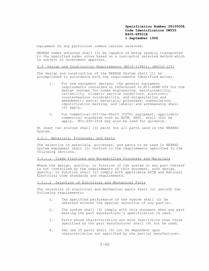
Specification Number 2810000ACode Identification OWY55 R400-SP501A 1 September 1996
3-40
equipment by any particular common carrier selected.
NEXRAD radar antennas shall (3) be capable of being readily transportedto the specified radar sites based on a contractor selected method whichis subject to Government approval.
3.3 Design and Construction Requirements (W210-119R1); (W4210-137)
The design and construction of the NEXRAD System shall (1) beaccomplished in accordance with the requirements identified below:.
1. For new equipment designs, the general equipmentrequirements contained or referenced in MIL-HDBK-454 for thedesign (except for human engineering, maintainability,reliability, climatic service conditions, electroniccountermeasure vulnerability, and encapsulation andembedment); parts; materials; processes; nomenclature,identification marking, and labels; and workmanship shall(2) apply.
2. For Commercial-Off-the-Shelf (COTS) equipment, applicablecommercial standards such as ASTM, ANSI, shall (2a) beapply. MIL-STD-2036 may also be used for guidance.
At least two sources shall (3) exist for all parts used in the NEXRADSystem.
3.3.1 Materials, Processes, and Parts
The selection of materials, processes, and parts to be used in NEXRADSystem equipment shall (1) conform to the requirements specified in thefollowing sections.
3.3.1.1 Trade Practices and Nonspecified Processes and Materials
Where the design, quality, or function of the system or any part thereofis not controlled by the requirements of this document, such design,quality, or function shall (1) comply with applicable ASTM and NationalElectrical Code standards and requirements.
3.3.1.2 Selection of Electrical and Mechanical Parts
The selection of electrical and mechanical parts shall (1) satisfy thefollowing requirements:
1. The specified performance of the system shall (2) beobtained without the special selection of any part(s).
2. The system shall (3) comply with this document when any partmeeting the part manufacturer's specification is used.
3. Parts whose characteristics are more restrictive than thosespecified by the part manufacturer shall (4) not be used.
4. The use of parts shall (5) not be dependent uponcharacteristics not specified by the part(s) manufacturer.

Specification Number 2810000ACode Identification OWY55 R400-SP501A 1 September 1996
3-41
5. Specified system performance shall (6) be obtained byinstalling acceptable parts at random as received from thepart manufacturer without subsequent replacement orinterchanging thereof.
3.3.1.3 Part Limits and Ratings (Electrical and Mechanical)
The part manufacturer's specifications and limits for any part shall (1)not be exceeded when the system is subjected to and operated under theconditions specified in Section 3.2.6 and in accordance with all otherrequirements of this document. Derating of parts shall (2) beaccomplished as necessary to assure the required reliability within thespecified operating conditions.
3.3.1.4 Mechanical Design
Unless basic component size and/or maintenance accessibility prohibit,all major equipment used in the NEXRAD System (e.g., computers andstorage devices) shall (1) be designed for a standard 19 inch rackmounting. All parts shall (2) be securely mounted and attached andshall (3) withstand the rigors of transportation, operation, andmaintenance without damage.
The NEXRAD System shall be designed to:
1. [Shall (4)] Allow localization of malfunctions to adefective LRU without disassembly or removal (extenderboards allowed).
2. [Shall (5)] Allow routine operation or maintenance withoutthe removal of structural members.
3. [Shall (6)] Allow direct access to LRUS, test points, andmaintenance adjustments without disassembly or removal(extender boards allowed).
3.3.1.5 Equipment Circuit Design
The NEXRAD System circuitry shall (1) be solid-state except in thoseareas of design where solid-state devices are not available, exhibit alow MTBF, are considered beyond the state-of-the-art, or are notconsistent with meeting lowest life cycle cost. All circuit designshall (2) be based on the following criteria except where noted:
1. Solid state circuit design shall (3) be based oncommercially available semiconductor devices manufactured todomestic (USA) standards, and available for delivery fromtwo or more domestic sources.
2. The use of the following shall (4) be minimized:
a. [Shall (4a)] Parts with ribbon leads.
b. Solder-in relays. (Plug-in relays shall (4b) be usedin lieu of solder-in relays wherever practical.)

Specification Number 2810000ACode Identification OWY55 R400-SP501A 1 September 1996
3-42
c. [Shall (4c)] Nonrepairable electrical subassemblies.
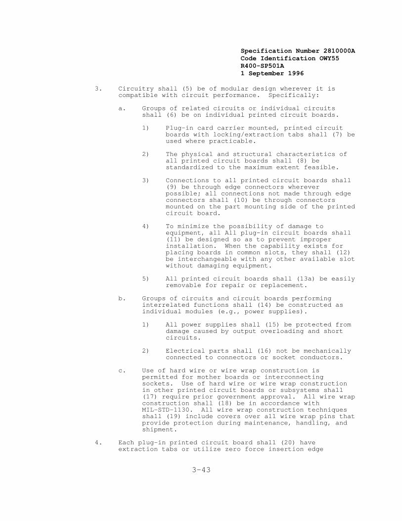
Specification Number 2810000ACode Identification OWY55 R400-SP501A 1 September 1996
3-43
3. Circuitry shall (5) be of modular design wherever it iscompatible with circuit performance. Specifically:
a. Groups of related circuits or individual circuitsshall (6) be on individual printed circuit boards.
1) Plug-in card carrier mounted, printed circuitboards with locking/extraction tabs shall (7) beused where practicable.
2) The physical and structural characteristics ofall printed circuit boards shall (8) bestandardized to the maximum extent feasible.
3) Connections to all printed circuit boards shall(9) be through edge connectors whereverpossible; all connections not made through edgeconnectors shall (10) be through connectorsmounted on the part mounting side of the printedcircuit board.
4) To minimize the possibility of damage toequipment, all All plug-in circuit boards shall(11) be designed so as to prevent improperinstallation. When the capability exists forplacing boards in common slots, they shall (12)be interchangeable with any other available slotwithout damaging equipment.
5) All printed circuit boards shall (13a) be easilyremovable for repair or replacement.
b. Groups of circuits and circuit boards performinginterrelated functions shall (14) be constructed asindividual modules (e.g., power supplies).
1) All power supplies shall (15) be protected fromdamage caused by output overloading and shortcircuits.
2) Electrical parts shall (16) not be mechanicallyconnected to connectors or socket conductors.
c. Use of hard wire or wire wrap construction ispermitted for mother boards or interconnectingsockets. Use of hard wire or wire wrap constructionin other printed circuit boards or subsystems shall(17) require prior government approval. All wire wrapconstruction shall (18) be in accordance withMIL-STD-1130. All wire wrap construction techniquesshall (19) include covers over all wire wrap pins thatprovide protection during maintenance, handling, andshipment.
4. Each plug-in printed circuit board shall (20) haveextraction tabs or utilize zero force insertion edge
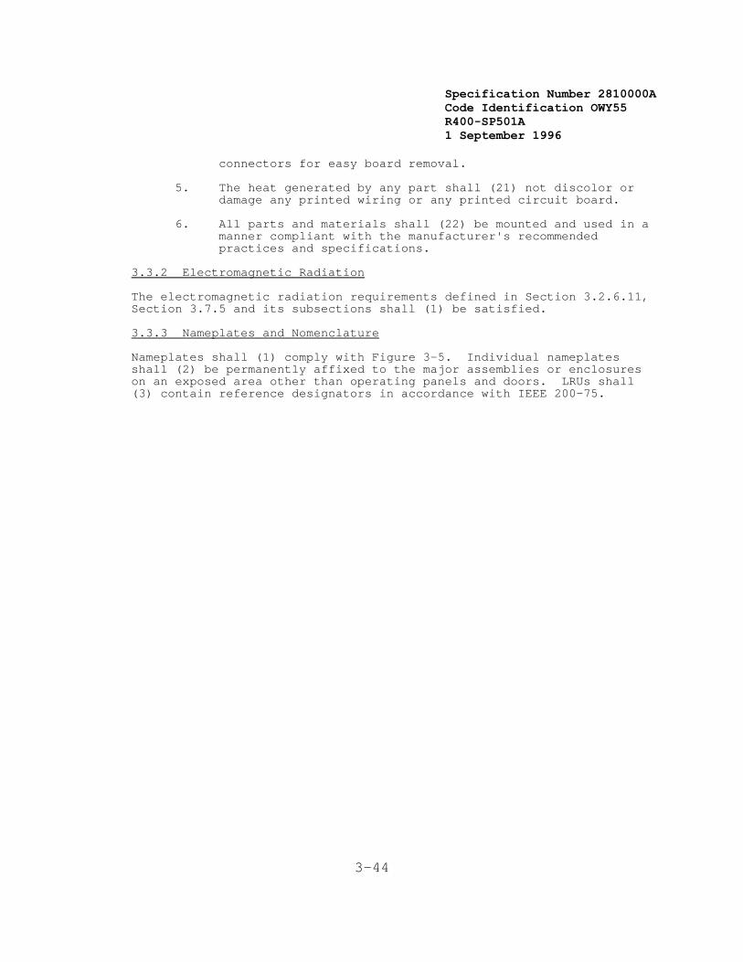
Specification Number 2810000ACode Identification OWY55 R400-SP501A 1 September 1996
3-44
connectors for easy board removal.
5. The heat generated by any part shall (21) not discolor ordamage any printed wiring or any printed circuit board.
6. All parts and materials shall (22) be mounted and used in amanner compliant with the manufacturer's recommendedpractices and specifications.
3.3.2 Electromagnetic Radiation
The electromagnetic radiation requirements defined in Section 3.2.6.11,Section 3.7.5 and its subsections shall (1) be satisfied.
3.3.3 Nameplates and Nomenclature
Nameplates shall (1) comply with Figure 3-5. Individual nameplatesshall (2) be permanently affixed to the major assemblies or enclosureson an exposed area other than operating panels and doors. LRUs shall(3) contain reference designators in accordance with IEEE 200-75.
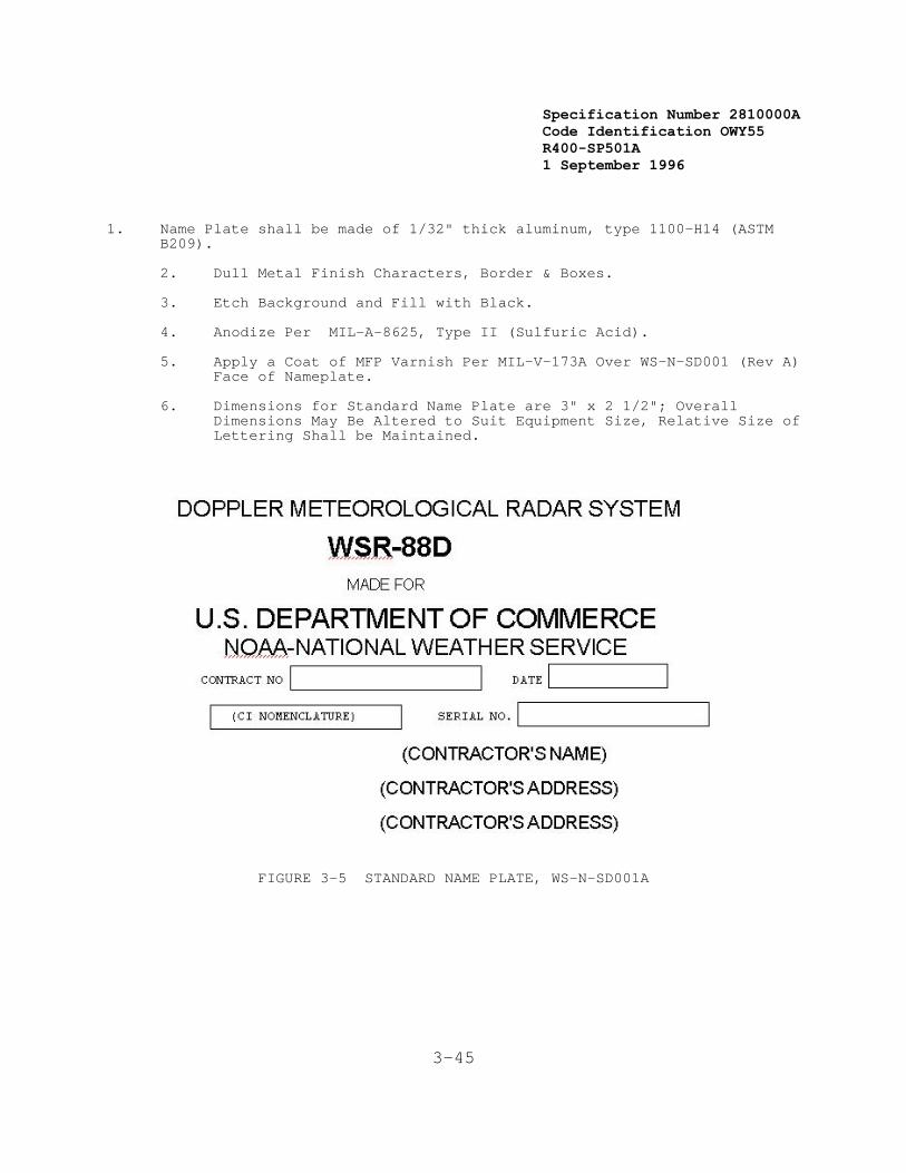
Specification Number 2810000ACode Identification OWY55 R400-SP501A 1 September 1996
3-45
1. Name Plate shall be made of 1/32" thick aluminum, type 1100-H14 (ASTMB209).
2. Dull Metal Finish Characters, Border & Boxes.
3. Etch Background and Fill with Black.
4. Anodize Per MIL-A-8625, Type II (Sulfuric Acid).
5. Apply a Coat of MFP Varnish Per MIL-V-173A Over WS-N-SD001 (Rev A)Face of Nameplate.
6. Dimensions for Standard Name Plate are 3" x 2 1/2"; OverallDimensions May Be Altered to Suit Equipment Size, Relative Size ofLettering Shall be Maintained.
FIGURE 3-5 STANDARD NAME PLATE, WS-N-SD001A
Specification Number 2810000ACode Identification OWY55 R400-SP501A 1 September 1996
3-46
3.3.4 Workmanship
The minimum standard of workmanship to be applied during fabricationshall (1) be compliant with Requirement Guideline 9 of MIL-HDBK-454.
3.3.5 Interchangeability
Each type of LRU shall (1) be physically, mechanically, structurally,and electrically interchangeable in and between all NEXRAD equipmentprocured under this document without modification and without causingany unit to deviate from the requirements of this document.
3.3.6 Safety
The NEXRAD System shall (1) be compliant in all respects with OSHASafety and Health Standards (29 CFR 1910) and with American NationalStandards Institute Standard ANSI C95.1-1982. In addition, thefollowing requirements of MIL-HDBK-454 shall be satisfied:
1. [Shall (2)] Guideline 1 - Safety (Personnel Hazard).
2. [Shall (3)] Guideline 3 - Flammability.
3. [Shall (4)] Guideline 45 - Corona and Electrical BreakdownPrevention.
3.3.7 Human Performance/Human Engineering
The NEXRAD equipment and facilities shall (1) comply with MIL-STD-1472. In general, the design of NEXRAD equipment and facilities supplied shall(2) provide for human engineering and biomedical factors that affecthuman performance.
3.3.7.1 Acoustic Noise Requirements
Acoustic noise requirements for equipment accessed by maintenancepersonnel only and for equipment in areas occupied by operationalpersonnel are defined in the following sections.
3.3.7.1.1 Equipment Accessed by Maintenance Personnel Only
The acoustic noise level of NEXRAD equipment which is normally accessedby maintenance personnel only shall (1) not exceed condition A of thetabulation of noise limits defined in section 3.3.7.1.3. Acoustic noiselevel requirements apply to operating free-standing equipment, with allinternal fans necessary for proper air flow and cooling operatingnormally.
Acoustic noise level measurements shall (2) be performed on operatingequipment. The measurements shall (3) be taken a distance of 1.0 meters from the cabinet sides and 1.5 meters up from the floor. Measurements shall (4) be taken on the air inlet and air exhaust sides of cabinets wherever air is drawn in or exhausted via the sides of cabinets. Measurements shall (5) be performed in an environment where ambientnoise levels do not constitute more than 5 percent of the noisegenerated by the equipment at any frequency.

Specification Number 2810000ACode Identification OWY55 R400-SP501A 1 September 1996
3-47
3.3.7.1.2 Equipment in Areas Occupied by Operational Personnel
The acoustic noise level of RPG and PUP equipment installed in areasoccupied by operational personnel shall (1) not exceed condition B ofthe tabulation of noise limits defined below. This shall (2) includeall RPG functional area equipment and all PUP functional area equipment. Optional noise suppression devices (acoustic panels, baffles, etc.) maybe used to satisfy this requirement. Individual measurement sets may beused for the RPG and PUP. Acoustic noise level requirements apply tooperating equipment with all internal fans necessary for proper air flowand cooling operating normally.
Acoustic noise level measurements shall (3) be performed on operatingequipment in an environment where ambient noise levels do not constitutemore than 5 percent of the noise generated by the equipment at anyfrequency. Measurements shall (4) be performed 0.8 meters from thefront, rear, and each side of the equipment (not the noise suppressiondevice) at a height of 1.2 meters.
3.3.7.1.3 Acoustic Noise Limits
The following tabulation provides the noise limits for NEXRAD equipmentexpressed in decibels (dB) with a reference of 0.0002 dynes per squarecentimeter.
FREQUENCY BANDS (Hz)
20- 75- 150- 300- 600- 1200- 2400- 4800- 9600- CONDITION 75 150 300 600 1200 2400 4800 9600 20000 A 100 89 82 76 73 70 68 67 66 B 79 68 60.2 52 48 45 43 42 41
3.3.7.2 Heating Requirements
At selected sites, the contractor shall provide a modular heatingcapability in the radome shall (1) be provided. One of three levels ofheat shall (2) be provided to correspond to three geographic temperaturezones, the coldest being -40 degrees Celsius. Resistive and/orinfra-red electric heating shall (3) be provided to produce:
1. [Shall (3a)] An acceptable working environment formaintenance personnel to work on the azimuth and elevationbearing and drive areas of the pedestal
2. [Shall (3b)] A minimum temperature of -5 degrees Celsius onthe internal pedestal components in the vicinity of theazimuth and elevation drives for safety concerns ofskin-to-metal contact.
Heating of the entire radome is not required. During normal operations,the radome interior shall (4) not require heating. The heating modeshall (5) be manually activated from the RDA maintenance position. Total power consumption for this heating capability shall (6) not exceed30 kW. Backup power support for the radome heat capability is notrequired.

Specification Number 2810000ACode Identification OWY55 R400-SP501A 1 September 1996
3-48

Specification Number 2810000ACode Identification OWY55 R400-SP501A 1 September 1996
3-49
3.3.8 Computer Software
The requirements described in this section shall (1) [all requirementsin this section are traced through this requirement] apply to allcomputer software used to satisfy the requirements of this document. These requirements relate to:
1. Computer Program Functional Composition
2. Design Techniques
3. Documentation Constraints
4. Coding Conventions and Standards
5. Language Standards
6. System Software Augmentation
7. Microprogramming
8. Microprocessor Software
9. Program Regeneration
3.3.8.1 Computer Program Functional Composition.
The computer program functional composition shall consist of computerprogram configuration items, computer program components, and modules asdefined below:
1. Computer Program Configuration Item (CPCI). A CPCI is theactual computer program end item in the form of computerinstructions and data stored on machine-readable media. ACPCI shall consist of one or more computer programcomponents.
2. Computer Program Component (CPC). A CPC is a functionallyand logically distinct part of a CPCI. A CPC is identifiedfor purposes of convenience in specifying and developing aCPCI as an assembly of subordinate elements. A CPC consistsof a logical composition of one or more subordinate orinterfacing modules.
3. Module. A module performs a complete logical process byexecution of a set of instructions which have clearlydefined inputs, processing logic, and outputs. A module isthe smallest set of executable statements assembled orcompiled.
3.3.8.1.1 Module Characteristics
A software module shall have a single name by which it is invoked. Ninety percent of all modules shall contain no more than 100 lines ofexecutable source code, excluding comments. No module shall exceed 200lines of executable source code, excluding comments. Each module shall
Specification Number 2810000ACode Identification OWY55 R400-SP501A 1 September 1996
3-50
contain a single entry point and a single exit.
3.3.8.1.2 Module Communication
Communication between modules shall be through well defined interfacecalls. Control paths shall be rigorously defined. Modules shall be referenced only as entities and shall always be referenced via their names. Communication between modules shall be limited to the passing ofdata, flags, or tables. Modules shall share only global data (i.e.,data known to the whole CPCI).
3.3.8.2 Design Techniques
Design techniques shall be used which facilitate the development ofreliable and maintainable software. These techniques shall includethose related to the use of structured design and structuredprogramming.
The responsibility for all aspects of the software design shall beretained by the contractor, even after Government participation indesign reviews.
3.3.8.2.1 Structured Design
All NEXRAD software shall be designed using structured designtechniques. Structured design is based on the technique of progressiverefinement of the software system architecture. This refinementproceeds from a high-level conceptualization represented by a top-levelstructure to a precise and detailed level represented by a low-levelstructure suitable for implementation.
Design of a lower level shall not begin until the design for the nextlevel above it is complete. The design for a level is not completeuntil:
1. All the design documentation has been completed, and
2. The design for the level has been reviewed (in a walkthroughor its equivalent).
The start of design of a lower level does not freeze the higher leveldesign. It is recognized that there is a constant inter-action betweenlevels as the design of one level may uncover weakness at higher levels. This iteration is allowable since it forces a more complete definitionof requirements at the higher level.
If a change in a higher level design is necessary, the modification andits interactions with previously designed modules shall be reviewedprior to any review of the lower level design which forced the change.
Each level in the hierarchy shall consist of a set of modules. Theprocessing performed by each module shall be described in the moduleprologue and in the program design language (PDL) description of themodule. PDL, also known as pseudo-code or structured English, is asemiformal specification language that is used to describe theprocessing performed by a module and the data used in the module.

Specification Number 2810000ACode Identification OWY55 R400-SP501A 1 September 1996
3-51
Specification Number 2810000ACode Identification OWY55 R400-SP501A 1 September 1996
3-52
3.3.8.2.2 Structured Programming
Structured programming, a systematic methodology for implementingprogram execution logic, shall be used for all NEXRAD software. A setof control structures shall be defined and only those structures shallbe allowed to alter the flow of control within a module. If possible,the unconditional branch is not to be used.
The choice of a set of control structures is dictated somewhat by thechoice of programming language. An example of a typical set of controlstructures follows:
1. Sequence - two or more contiguous operations.
2. If-then-else - conditional branch to one of two operationsand continue.
3. Do while - operation continued while a condition is true.
4. Case - select one of several alternatives.
Control structures shall be implemented via macros or a precompiler ifthey are not part of the programming language in use.
3.3.8.3 Documentation Constraints
NEXRAD software documentation shall consist of the following:
1. Structure Diagrams
2. Data Flow Diagrams
3. Module Prologues
4. Program Design Language (PDL) Descriptions
5. Source Code
6. Data Dictionary
The structure diagrams shall show the hierarchical relationship amongthe software modules, including the interface between modules. Thestructure diagrams, or other Government approved method, shall also showthe flow of control among the modules.
Data flow diagrams are network representations of the system that showthe flow of data (rather than control). The data flow diagrams shallinclude the representation of the data structures in the system as wellas the processing (transforms), input sources, and output destinations.
Module prologues shall provide descriptive information on the module,including inputs and outputs, files which are used, and other moduleswhich are called.
The program design language (PDL) descriptions shall use a semiformalspecification language and shall include sections which describe the
Specification Number 2810000ACode Identification OWY55 R400-SP501A 1 September 1996
3-53
processing functions performed by a module. The processing sectionshall use English phrases to describe the functions performed by themodule. Each phrase shall specify an action and shall be drawn from theset of key words and syntax rules that make up the PDL standards.
Complete source code and related documentation shall be provided for alloperational and support software.
One automated data dictionary shall be generated that will contain allof the data within the system. Each data item shall be included alongwith an English description and all of its relevant elements (e.g.,type, size, range, index, etc.). Report generation capability shall beprovided.
3.3.8.4 Coding Convention and Standards
The following conventions and standards are required for all softwarecode:
1. Code Indentation. Lines of code within a control structureshall be indented to the corresponding logical depth. (Thisenables the reader to quickly localize the code affected bythe control structure using only visual inspection.)
2. Global Data and Work Areas. Standards for the use of globaldata and work areas shall be defined at the start of designand enforced throughout the development effort.
3. Standard Routines. Routines for frequently repeated codingunits (e.g., module initialization and register setdefinitions) shall be identified.
4. Libraries. Routines that perform frequently requiredfunctions shall be maintained in a library.
5. Self-Modifying Code. Code which modifies itself or the codeof other modules during execution shall not be used.
6. Line Length. No more than one source statement shall beallowed per line. In no case shall an executable sourcestatement be continued for more than two lines. In no caseshall a non-executable statement be continued for more thanseven lines.
7. Branch. If an unconditional branch is used it shall beaccompanied by enough comments to make its purpose and justification for use clear.
8. Data Types. The data type for each data structure(constant, individual data element, or array) in a moduleshall be explicitly defined (even if the implementationlanguage does not require it).
9. Comments. Each module shall contain sufficient comments toenable easy debugging, testing, modification, andmaintenance of the module. A prologue, consisting of a
Specification Number 2810000ACode Identification OWY55 R400-SP501A 1 September 1996
3-54
series of comments prior to any executable code or datadefinitions, shall be provided for each module. Thisprologue shall contain, at a minimum:
a. The name and version of the module,
b. Function of the module,
c. Invocation method and parameters for the module,
d. Files and tables used by the module,
e. Language used in the module,
f. Inputs to the module and their format,
g. Outputs from the module and their format,
h. Other modules called by this module,
i. Name of the programmer responsible for the module,
j. Date the module was first coded and the dates of anysubsequent revisions,
k. Error conditions,
1. Miscellaneous information, such as interrupt level,privileged status, registers used, and reentry, and
m. Compilation/assembly and linking instructions.
The PDL used to describe the module shall appear after the moduleprologue.
In the body of the module, comments shall be used to clarify theoperation of the module and shall appear with a frequency of at leastone comment per five source lines. Complex instruction sequences (e.g.,interrupt handling) shall be extensively commented. Comments shallaccurately reflect the code. Whenever code is changed, thecorresponding comments and PDL shall be modified to reflect that change.
10. The following coding practices shall not be used:
a. Absolute referencing of memory (without priorGovernment approval),
b. Use of literal in operative statements. All constantsshould be declared, commented upon, and used by theirsymbolic names,
c. Resetting the index of a loop in the body of the loop,
d. Branching into a loop from outside the loop, and
e. Use of the same argument as both the input and the

Specification Number 2810000ACode Identification OWY55 R400-SP501A 1 September 1996
3-55
output to a module.

Specification Number 2810000ACode Identification OWY55 R400-SP501A 1 September 1996
3-56
3.3.8.5 Language Standards
Only one PDL shall be used. Only Government approved control structuresshall be used. The use of indented PDL code to highlight logicstructure and the use of self-defining data names are required.
All software developed for the NEXRAD System shall be written in a highorder programming language except for those cases where it can be shownthat memory constraints, processing efficiency requirements, or someother system restrictions dictate the use of assembly language. If, in order to meet the requirements of this document, it is necessary to codecertain components of the NEXRAD System in assembly language, thespecific modules affected shall be identified and the appropriatejustification provided so that the Government may review and decide whether the exception is justified. No modules shall be coded inassembly language without prior Government approval.
The high order language used is subject to Government approval but, at aminimum, shall meet the following requirements:
1. An ANSI or DOD standard shall exist for the language.
2. The implementation of the language used in the NEXRAD Systemshall comply with an ANSI or DOD standard, and shall have undergone formal verification by a standards agency.
3.3.8.6 System Software Augmentation
When vendor-supplied commercial quality, off-the-shelf* system softwareis used in the implementation of the NEXRAD operational software, thefollowing rules apply:
1. Augmentations shall be limited to the design of newsoftware. No augmentations shall be embedded within thevendor-supplied, off-the-shelf system software.
2. All augmentations shall interface with the vendor-suppliedoperating system.
3. Augmentation software (including interface software)developed for the NEXRAD System shall not compromise thecapability to support any off-the-shelf software (e.g., anoperating system or a data base management system) over thelife of the system.
3.3.8.7 Microprogramming
Microprogramming (or microcoding) is a method of implementing thecontrol functions of a computer. Modifications or additions to thecontrol functions of a processor shall be subject to review and approvalby the Government. All newly developed microprograms shall comply withrequirements for software listed in Section 3.3.8.3. With Governmentapproval, the requirements for the use of a high order language andstructured programming techniques may be waived in the case ofmicrocode. Any microcode implementation shall be reproducible by theGovernment.

Specification Number 2810000ACode Identification OWY55 R400-SP501A 1 September 1996
3-57
3.3.8.8 Microprocessor Software
Software intended for execution on a microprocessor shall be subject tothe same software constraints and requirements as the software intendedfor execution on large-scale processors. Microprocessor software shallsatisfy all the requirements called out in Sections 3.3.8.1 through 3.3.8.7 of this document. This includes the requirements for the use ofa high order language and structured programming methodologies.
3.3.8.9 Program Regeneration
All software delivered shall be capable of being regenerated by theGovernment using contractually delivered support software (or firmware)and hardware.
For all existing, commercially available software provided to meet therequirements of this document, the Government shall be supplied updatesto the software until the end of the Production Phase. Updates shallinclude object code and documentation revisions as appropriate. If theGovernment encounters errors in any of this commercial software,corrections shall be made in accordance with standard commercialpractice until the end of the Production Phase.
3.3.9 Firmware
Firmware is defined to consist of those programs or microprograms thatreside in the class of memory that cannot be dynamically modified by thecomputer during its processing. The class of memory includes read-only memory (ROM), programmable read-only memory (PROM), or writable controlstore (WCS). Documentation of the firmware memory shall (1) be includedin the hardware development specification while documentation of thefirmware program shall (2) be included in the software developmentspecification and product specification (as appropriate). All firmwareshall (3) be subject to all software constraints and requirements. Anyfirmware implementation shall (4) be reproducible by the Government.
3.4 Documentation
The documentation items that shall (1) be prepared for the NEXRADprogram, along with a detailed description of the requirements of eachdocumentation item, will be itemized in the Contract Data Requirements List (CDRL).
3.5 Logistics
The NEXRAD System shall (1) be designed so that it can remain fullyoperational through the use of normal maintenance procedures throughoutits specified useful life period. The logistics system for NEXRAD shall(2) coordinate the hardware configuration with the availability andmaintainability requirements. The NEXRAD logistics system shall (3) bebased on existing principal user logistic systems and shall (4) augmentthose existing systems to the maximum extent possible. The design ofthe logistics system shall (5) assume that NEXRAD will be maintained byGovernment personnel.
Specification Number 2810000ACode Identification OWY55 R400-SP501A 1 September 1996
3-58
3.5.1 Maintenance
System maintenance shall (1) include all maintenance equipment,software, and procedures required for maintaining the NEXRAD System, andshall (2) include both periodic and corrective maintenance actions.
3.5.1.1 Maintenance Concept
The general NEXRAD maintenance approach shall (1) be to centrallymonitor system performance at the RDA, RPG, and PUP level, to localizethe failures through the use of software and hardware maintenancefeatures, and to replace the failed Line Replaceable Unit (LRU)* fromon-site spares, whenever available. The actual repair of a replaceditem will be performed either in a designated on-site repair area withequipment not part of the operational system or at a depot. Diagnosticsoftware and maintenance features shall (2) be designed to rapidlyisolate malfunctions to the LRU level.
The NEXRAD maintenance practices, which shall (3) augment themaintenance practices of the principal users, require that theindividual who performs on-equipment, on-site maintenance (removal andreplacement of the LRU) will also perform any off-equipment, on-sitemaintenance (repair of the faulty LRU). If a failed LRU is not repairedon-site, it will be coded for off-site repair and sent to a repairdepot. The concept of removal and replacement shall (4) be implemented,and maximum use shall (5) be made of depot level repair, consistent withthe LCC analysis.
3.5.1.2 Personnel Skill Level
The NEXRAD logistics system shall (1) be designed to allow the system tobe maintained by the personnel of the principal users.
The skill of these personnel varies. For those sites staffed by DOD,maintenance personnel will consist of skill level 5 (journeyman) airmenor equivalent. Individual qualifications of DOD maintenance personnelvary from graduates of basic electronic and systems technical schoolswith several years experience to new graduates of these schools. NWSand FAA will, in general, use skilled maintenance personnel with severalyears experience.
Maintenance personnel will have completed the NEXRAD maintenancetraining before being responsible for maintenance of the NEXRADequipment.
3.5.1.3 Diagnostic Techniques
Fault isolation to the LRU without component removal shall (1) beincorporated into the system design. This shall (2) be achieved throughthe use of Built-In Test Equipment (BITE), automatic alarms, indicatorlights, and computer diagnostic and system diagnostic software. Theequipment shall (3) be designed to minimize the use of special supportequipment. Easily accessible test points shall (4) be provided to facilitate the use of external test equipment. The BITE system shall(5) provide remote performance monitoring, parameter measurements, andequipment adjustments sending performance information to the appropriate
Specification Number 2810000ACode Identification OWY55 R400-SP501A 1 September 1996
3-59
maintenance control section of the unit responsible for maintaining thesystem.
3.5.1.4 Calibration
Calibration will be conducted to maintain operational equipmentperformance parameters and characteristics to specification tolerances. To the degree warranted by good engineering practices, development ofperformance diagnostic techniques using external support equipment willbe oriented toward providing measurements more precisely than thetolerances of the operating equipment/performance parameters to bemeasured. Precision Measuring Equipment Laboratory (PMEL) support willbe provided by the Government.
3.5.1.5 Maintenance Environment
Equipment will be located at fixed worldwide locations. For DOD,on-site maintenance will be accomplished in accordance with AFR 66-1. For FAA, on-site maintenance will be accomplished in accordance withDOT/FAA Order 6000.27. For NWS, on-site maintenance will conform withWeather Service Operations Manual (WSOM) Chapter H-50, EquipmentMaintenance Program, and WSOM Chapter H-98, Engineering DirectivesSubsystem. Off-site maintenance will be performed by a designatedprincipal user organization. That organization will arrange for serviceengineering modifications.
On-site maintenance personnel will perform both on-equipment and off-equipment maintenance. The NEXRAD equipment shall (1) be designed to bemaintained by an organization that uses the same technician toaccomplish both categories of maintenance.
3.5.1.7 Depot Maintenance
The Government will provide a single central depot to support all LRUsnot repaired on-site.
3.5.1.8 Supportability
NEXRAD system support will be consistent with: a single OperationalSupport Facility which provides engineering, operations support, andsoftware systems maintenance; a single depot which provides centralrepair and reprocurement services; and a separate supply depot for eachprincipal user.
3.5.2 Supply
Spare parts, hold provisioning conferences, and provisioningdocumentation shall (1) be provided in accordance with the contractschedule. Site spares and initial depot spare parts shall (2) beprovided. The site spares shall (3) be LRUS. The provisioningconferences will be held at the discretion of the Government. At theprovisioning conferences, Provisioning data drawings and other servicesrelated to the Government determination of provisioning items shall (4)be provided. Provisioning documentation consisting of provisioningparts list, numerical parts list, long lead-time item list, and itemidentification/item logistics data records shall (5) be provided. A
Specification Number 2810000ACode Identification OWY55 R400-SP501A 1 September 1996
3-60
single principal user will be responsible for ordering all non-consumable NEXRAD supplies. This agency will redistribute supplies tothe other NEXRAD principal users utilizing normal supply systems wherepossible. Spare parts shall (6) be made available in sufficient time toreplenish inventories without impacting system operation. The guaranteeshall (7) be for 20 years after the first limited production modelinstallation.
3.6 Training
Initial training to a cadre of personnel from each of the principalusers shall [not numbered, not traced] be provided; this initialtraining shall cover both the operation and maintenance of the NEXRADSystem and shall be a combination of formal classroom courses andhands-on equipment training. The initial cadre of personnel will thenassume responsibility for training additional personnel at the NEXRADtraining facilities.
Separate training shall [not numbered, not traced] also be provided thatwill enable designated personnel to maintain delivered software.
3.6.1 Limited Production Training
During limited production, at the Government's option, training forprincipal user personnel shall [not numbered, not traced] be provided.These principal user personnel will be engaged in the followingactivities or assignments:
- Operational Test and Evaluation - Software Maintenance - Initial Cadre Instruction - Field Operations and Maintenance - Depot Repair/Logistics
Specification Number 2810000ACode Identification OWY55 R400-SP501A 1 September 1996
3-61
FUNCTIONAL AREAS
Specification Number 2810000ACode Identification OWY55 R400-SP501A 1 September 1996
3-62
3.7 Functional Area Characteristics
Characteristics are specified herein for the NEXRAD functional areas,consisting of the following:
1. Radar Data Acquisition
2. Radar Product Generation
3. Principal User Processing
4. Communications
5. Facilities
6. Support

Specification Number 2810000ACode Identification OWY55 R400-SP501A 1 September 1996
3-63
RADAR DATA ACQUISITION (RDA) SEGMENT
Specification Number 2810000ACode Identification OWY55 R400-SP501A 1 September 1996
3-64
3.7.1 Radar Data Acquisition Functional Area
The Radar Data Acquisition (RDA) functional area shall (1) provide thecapability to acquire, perform signal processing on, and transferweather radar data to the Radar Product Generation (RPG) functionalarea, either directly, if the RDA and RPG are collocated, or via theCommunications functional area, if the RDA and RPG are not collocated.
3.7.1.1 General Requirements
The RDA shall (1) include an antenna, pedestal, radome, transmitter,receiver, signal processing capability, control capability, monitoringand error detection capability, and an interfacing capability. Thesecapabilities shall (2) provide for the detection and measurement ofweather phenomena to the extent defined in Section 3.7.1.2, whilemeeting the reliability, maintainability, and availability requirementsdefined in Sections 3.2.3, 3.2.4, and 3.2.5, and while operating withinthe environmental conditions defined in Section 3.2.6.
Monitoring and control functional capabilities (defined in Section3.7.1.9) shall (3) be included in the RDA to support both operations andmaintenance activities.
The RDA shall (4) be capable of operation in at least two modes,designated Mode A and Mode B. All requirements of Section 3.7.1 shall(5) apply to both Modes A and B. Selection of Mode B, for short range,clear air observations shall (6) require a manual action from the unitcontrol position. Deselection of Mode B shall (7) be accomplishedautomatically. Criteria for automatic mode selection/deselection areprovided in Appendix I. A manual capability to return to Mode A shall(8) be provided at the unit control position.
For selected sites a long pulse capability shall (9) be provided. Radarsystem parameter changes allowed for this long pulse capability are a 3dB pulse volume depth less than 750 meters [shall (9a)], a Nyquistvelocity greater than 11 ms-1 [shall (9b)], reflectivity measurement outto a maximum range of 230 km [shall (9c)], and a longer system dwelltime [shall (9d)] to allow attainment of the requirements of Section3.7.1.2.3.1.
The RDA shall (10) be designed for unattended operation.
The RDA shall (11) operate using commercial power as specified inSection 3.7.5.2.1. In the event that primary power fails or degradesbelow acceptable limits, the RDA running under secondary (backup) powershall (12) become operational automatically. Acquisition of radar dataduring periods of either primary or backup power failure is notrequired. Following a power outage of less than or equal to 15 secondswhile acquiring base data, the RDA shall (13) resume acquisition at theinterrupted elevation scan as soon as the antenna and transmitter havereturned to stable operational conditions. The elevation scan which wasin progress at the point of power outage shall (14) be restarted with afull collection of base data, and, thereafter, the remaining portions ofthe volume coverage shall (15) be completed. For power outages inexcess of 15 seconds, the volume coverage shall (16) be restarted.
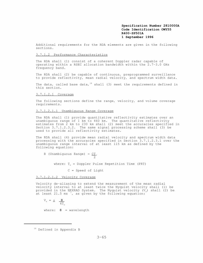
Specification Number 2810000ACode Identification OWY55 R400-SP501A 1 September 1996
18 Defined in Appendix B
3-65
Additional requirements for the RDA elements are given in the followingsections.
3.7.1.2 Performance Characteristics
The RDA shall (1) consist of a coherent Doppler radar capable ofoperating within a RSEC allocation bandwidth within the 2.7-3.0 GHzfrequency band.
The RDA shall (2) be capable of continuous, preprogrammed surveillanceto provide reflectivity, mean radial velocity, and spectrum width data.
The data, called base data,18 shall (3) meet the requirements defined inthis section.
3.7.1.2.1 Coverage
The following sections define the range, velocity, and volume coveragerequirements.
3.7.1.2.1.1 Unambiguous Range Coverage
The RDA shall (1) provide quantitative reflectivity estimates over anunambiguous range of 1 km to 460 km. The quantitative reflectivityestimates from 2 km to 230 km shall (2) meet the accuracies specified inSection 3.7.1.2.3.2. The same signal processing scheme shall (3) beused to provide all reflectivity estimates.
The RDA shall (4) provide mean radial velocity and spectrum width dataprocessing with the accuracies specified in Section 3.7.1.2.3.1 over theunambiguous range interval of at least 115 km as defined by thefollowing equation:
R (Unambiguous Range) = CTs 2
where: Ts = Doppler Pulse Repetition Time (PRT)
C = Speed of Light
3.7.1.2.1.2 Velocity Coverage
Velocity de-aliasing to extend the measurement of the mean radialvelocity interval to at least twice the Nyquist velocity shall (1) beprovided in the NEXRAD System. The Nyquist velocity (Va) shall (2) beat least 21.5 ms '1, as given by the following equation:
Va = + 8 4Ts
where: 8 = wavelength
Specification Number 2810000ACode Identification OWY55 R400-SP501A 1 September 1996
3-66
3.7.1.2.1.3 Volume Coverage
The RDA shall (1) provide the capability for a volume coverage definedby a rotated triangular section extending in range from the antenna tothe specified range, 360 degrees in azimuth relative to the antenna'srotational axis, and from -1 degree to 45 degrees in elevation relativeto the antenna's rotational axis and the horizontal plane at theantenna. However, there is no requirement for coverage above 70,000feet Mean Sea Level (MSL).
A number of automatic antenna scanning programs shall (2) be provided. One scanning program shall (3) provide, for a volume scan time of fiveminutes, a sample of the coverage volume. This sample shall (4) consistof 14 unique elevation scan levels, from zero degrees to +20 degrees inelevation, with at least the lowest six degrees of elevation having nogaps between the one-way pattern 3 dB points of adjacent elevationscans. This scan strategy will be designated Scan Strategy 1.
Another scanning program shall (5) provide for a sample of the coveragevolume of nine unique elevation angles from zero degrees to +20 degreesin elevation, for a volume scan time of six minutes. The lowest fourdegrees of elevation shall (6) have no gaps between the one-way pattern3 dB points of adjacent elevation scans. This scan strategy will bedesignated Scan Strategy 2.
The scanning rate may vary with elevation, but should be consistent withreasonable dwell times (TD) for the required system performance forreflectivity and radial velocity data. Additional scan strategies arespecified in Appendix I.
3.7.1.2.1.4 Spot Blanking
The RDA shall (1) provide the capability to inhibit transmission ofradiated power for up to five (5) separate areas within any volumecoverage pattern. Blanking is defined up to 25 dB reduction in powerfrom that occurring at the main (center) lobe of the radiated beam.
These selectable areas shall (2) be capable of being defined by anuppper and lower elevation angle and a beginning and ending azimuthangle with a selection resolution of one degree. These data shall (3) becapable of being entered only through OSF-controlled adaptationparameters at the RDA. There shall (4) be the capability of invoking orprohibiting spot blanking from the Unit Control Position.
The design of the spot blanking shall (5) not impose any undue physicalor electronic constraints on the transmitter and receiver assemblies ofthe RDA, and shall (6) be done in such a manner as to minimize anydisruption to the meteorological content of the radar data, as well asany clutter suppression invoked at the time.
3.7.1.2.2 Sample Interval
The following sections define the azimuth and range sample intervalrequirements.

Specification Number 2810000ACode Identification OWY55 R400-SP501A 1 September 1996
3-67
3.7.1.2.2.1 Azimuth Sample Interval
The RDA shall (1) provide an azimuth sample interval of not greater than1.055 degrees for elevations 7 degrees or less and 1.095 degrees for allother elevations.
3.7.1.2.2.2 Range Sample Interval
The RDA shall (1) provide a range sample interval of not greater than 1km, from 1 km to 230 km, including the effects of range averaging, forreflectivity measurements. The RDA shall (2) provide a range sampleinterval of not greater than 2 km from 230 km to 460 km for reflectivitymeasurements.
The RDA shall (3) provide a range sample interval of not greater than250 meters for mean radial velocity and spectrum width measurements.
3.7.1.2.3 Accuracy and Precision
The following sections define the mean radial velocity, spectrum width,reflectivity, and range accuracy and precision requirements.
The RDA shall (1) provide the capability of operating over a range ofdwell times compatible with nominal scan rates of from 0.5 rpm to 3.2rpm.
Specification Number 2810000ACode Identification OWY55 R400-SP501A 1 September 1996
3-68
3.7.1.2.3.1 Mean Radial Velocity and Spectrum Width
For the range of possible dwell times (TD) and twice the Nyquistvelocities (Va) in the system, the RDA shall (1) provide estimates ofmean radial velocity (v̂) and spectrum width (y*) as follows:
1. Mean Radial Velocity
Accuracy: For a true spectrum width (Note 1) of 4 ms-1 thestandard deviation in the estimate of the mean radialvelocity shall (2) be less than or equal to 1.0 ms-1
including quantization errors, for S/N greater than 8 dB. Precision: 0.50 ms-1 (Note 4)
2. Spectrum Width (Note 2)
Accuracy: For a true spectrum width of 4 ms-1 thestandarddeviation in the estimate of the spectrum widthshall (3) be less than or equal to 1.0 ms-1 includingquantization errors, for S/N greater than 10 dB.Precision: 0.50 ms-1 (Note 4)
_______________________________Note 1: True spectrum width is defined as one standard deviation of
the meteorological phenomenon spectrum width within asampled volume for which the indicated accuracy applies. Stated accuracy values apply for Nyquist velocities of thesystem. (Gaussian spectrum assumed.)
Note 2: Spectrum widths of 1 to at least 10 ms-1 shall (4) becalculated. Spectrum widths larger than 10 ms-1 shall (5)be displayed as being 10 ms-1. Significant biasesintroduced by the computational technique shall (6) beminimized.
Note 3: Not used.
Note 4: Precision is defined as the quantization, the smallestresolvable increment.
Specification Number 2810000ACode Identification OWY55 R400-SP501A 1 September 1996
3-69
3.7.1.2.3.2 Reflectivity
For the range of possible dwell times, the RDA shall (1) provideestimates of reflectivity from 2 to 230 km [shall (1a)], averaged over 1km range bins [shall (1b)], and meeting the following requirements:
[Shall (1c)] Accuracy: 1 dB at S/N > 10 dB (Note 3) (includingonly the error due to meteorological signal fluctuations). Automatic calibration shall (2) reduce system hardware drifterrors to less than 1 dB.
Precision: 1 dB (Note 4) [shall (1d)].
3.7.1.2.3.3 Range
The error in range placement of base data output from the RDA due totiming instabilities shall (1) be less than 50 meters.
3.7.1.2.4 Minimum Detection Capability and Dynamic Range
The RDA minimum detection capability shall (1) provide at least a 0 dBsignal to noise ratio for a -7.5 dBZe target at 50 km. The effectivedynamic range of the RDA shall (2) be at least 93 dB for bothreflectivity and velocity data. The RDA shall (3) not make use of RFSensitivity Time Control (STC).
3.7.1.3 Antenna Assembly
The antenna assembly shall (1) include items such as a mountingpedestal, drive mechanism(s), rotary joint, transmit and receive feedhorn, reflector, radome and other items needed to comply with themechanical and electrical requirements described in this document. Theantenna shall (2) be designed to be mounted inside a radome atop atower. The tower, when required, shall (3) be available in 5 meterheight increments,and shall (4) have a maximum height of 30 meters. Theantenna shall (5) meet all requirements herein while operating under theenvironmental conditions defined in Section 3.2.6.
_____________________________Note 1: Not used.
Note 2: Not Used.
Note 3: Accuracy is defined as one standard deviation (SD) of theestimate, including effects of precision.
Note 4: Precision is defined as the quantization, the smallestresolvable increment.
Specification Number 2810000ACode Identification OWY55 R400-SP501A 1 September 1996
19Defiuned in Appendix B.
3-70
The antenna performance requirements are derived from the RDAperformance requirements contained in Section 3.7.1.2 with the exceptionof the following specific requirements:
1. [Shall (6)] Type: Single pencil beam.
2. [Shall (7)] Antenna Pattern: Median gain19 of < -10 dBi
3. [Shall (8)] Half Power Beamwidth in Azimuth and Elevation: <1 degree.
4. Sidelobe Levels: In any plane, the first sidelobe shall (9)be less than or equal to -25 dB relative to the peak of thebeam. In the region between + 2 and + 10 degrees, thesidelobe level shall (10) lie below the straight lineconnecting -25 dB at + 2 degrees and -34 dB at + 10 degrees. Between + 10 degrees and + 180 degrees, the sidelobeenvelope shall (11) be less than or equal to -40 dB relativeto the peak of the beam. Beyond + 10 degrees, the peak ofan individual sidelobe may be averaged with the peak of thetwo nearest sidelobes, one on either side; or with the peaksof the four nearest sidelobes, two on either side, providedthat the level of no individual sidelobe exceeds the -40 dBlevel by more than 6 dB and that the combined angular extentof all peaks exceeding -40 dB does not exceed 30 degrees.
5. Cross Polarization Radiation: In any plane, the crosspolarization radiation shall (12) be at or below the levelspecified for the sidelobe and backlobe levels of thecopolarized radiation within the angular regions applicableto these lobes. Within the main lobe angular region, thecross polarization component shall (13) be at least 25 dBbelow the peak of the main beam of the copolarizedradiation.
6. [Shall (14)] Beam location reporting error < 0.15 degrees.
7. [Shall (15)] Polarization: linear horizontal.
The antenna assembly shall (16) be designed to facilitate removal andreplacement of any portion except the antenna reflector, radome, and thepedestal. The antenna assembly shall (16) be constructed to bedisassembled and reassembled for maintenance and repair at the top ofthe antenna tower using tools supplied.
The antenna assembly design shall (17) include provisions for routineinspection of critical internal pedestal and drive mechanism partswithout disassembly. The design shall (18) allow any maintenanceactivity to be completed within the repair times defined in Section3.2.4 (Maintainability).
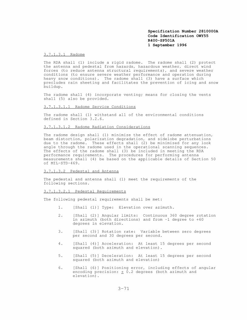
Specification Number 2810000ACode Identification OWY55 R400-SP501A 1 September 1996
3-71
3.7.1.3.1 Radome
The RDA shall (1) include a rigid radome. The radome shall (2) protectthe antenna and pedestal from hazards, hazardous weather, direct windforces (to reduce antenna structural requirements), and severe weatherconditions (to ensure severe weather performance and operation duringheavy snow conditions). The radome shall (3) have a surface whichprecludes rain sheeting and facilitates the prevention of icing and snowbuildup.
The radome shall (4) incorporate venting; means for closing the ventsshall (5) also be provided.
3.7.1.3.1.1 Radome Service Conditions
The radome shall (1) withstand all of the environmental conditionsdefined in Section 3.2.6.
3.7.1.3.1.2 Radome Radiation Considerations
The radome design shall (1) minimize the effect of radome attenuation,beam distortion, polarization degradation, and sidelobe perturbationsdue to the radome. These effects shall (2) be minimized for any lookangle through the radome used in the operational scanning sequences. The effects of the radome shall (3) be included in meeting the RDAperformance requirements. The procedures for performing antennameasurements shall (4) be based on the applicable details of Section 50of MIL-STD-469.
3.7.1.3.2 Pedestal and Antenna
The pedestal and antenna shall (1) meet the requirements of thefollowing sections.
3.7.1.3.2.1 Pedestal Requirements
The following pedestal requirements shall be met:
1. [Shall (1)] Type: Elevation over azimuth.
2. [Shall (2)] Angular limits: Continuous 360 degree rotationin azimuth (both directions) and from -1 degree to +60degrees in elevation.
3. [Shall (3)] Rotation rate: Variable between zero degreesper second and 30 degrees per second.
4. [Shall (4)] Acceleration: At least 15 degrees per secondsquared (both azimuth and elevation).
5. [Shall (5)] Deceleration: At least 15 degrees per secondsquared (both azimuth and elevation)
6. [Shall (6)] Positioning error, including effects of angularencoding precision: + 0.2 degrees (both azimuth andelevation).
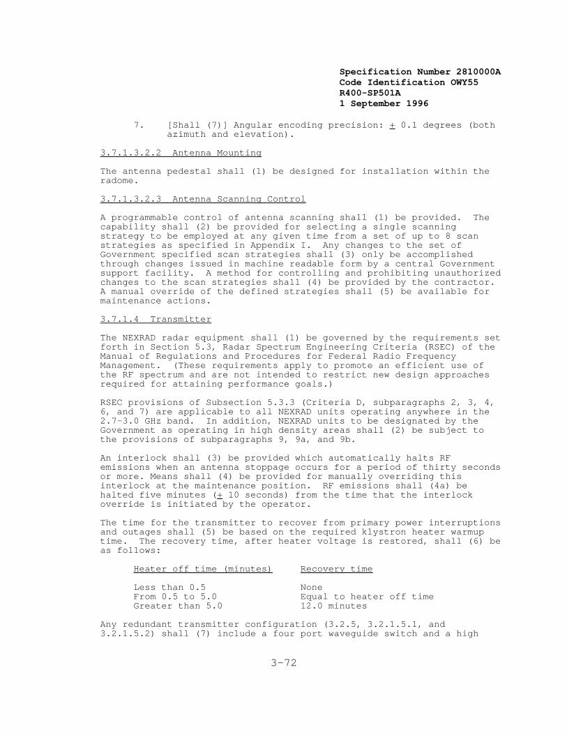
Specification Number 2810000ACode Identification OWY55 R400-SP501A 1 September 1996
3-72
7. [Shall (7)] Angular encoding precision: + 0.1 degrees (bothazimuth and elevation).
3.7.1.3.2.2 Antenna Mounting
The antenna pedestal shall (1) be designed for installation within theradome.
3.7.1.3.2.3 Antenna Scanning Control
A programmable control of antenna scanning shall (1) be provided. Thecapability shall (2) be provided for selecting a single scanningstrategy to be employed at any given time from a set of up to 8 scanstrategies as specified in Appendix I. Any changes to the set ofGovernment specified scan strategies shall (3) only be accomplishedthrough changes issued in machine readable form by a central Governmentsupport facility. A method for controlling and prohibiting unauthorizedchanges to the scan strategies shall (4) be provided by the contractor. A manual override of the defined strategies shall (5) be available formaintenance actions.
3.7.1.4 Transmitter
The NEXRAD radar equipment shall (1) be governed by the requirements setforth in Section 5.3, Radar Spectrum Engineering Criteria (RSEC) of theManual of Regulations and Procedures for Federal Radio FrequencyManagement. (These requirements apply to promote an efficient use ofthe RF spectrum and are not intended to restrict new design approachesrequired for attaining performance goals.)
RSEC provisions of Subsection 5.3.3 (Criteria D, subparagraphs 2, 3, 4,6, and 7) are applicable to all NEXRAD units operating anywhere in the2.7-3.0 GHz band. In addition, NEXRAD units to be designated by theGovernment as operating in high density areas shall (2) be subject tothe provisions of subparagraphs 9, 9a, and 9b.
An interlock shall (3) be provided which automatically halts RFemissions when an antenna stoppage occurs for a period of thirty secondsor more. Means shall (4) be provided for manually overriding thisinterlock at the maintenance position. RF emissions shall (4a) behalted five minutes (+ 10 seconds) from the time that the interlockoverride is initiated by the operator.
The time for the transmitter to recover from primary power interruptionsand outages shall (5) be based on the required klystron heater warmuptime. The recovery time, after heater voltage is restored, shall (6) beas follows:
Heater off time (minutes) Recovery time
Less than 0.5 None From 0.5 to 5.0 Equal to heater off time Greater than 5.0 12.0 minutes
Any redundant transmitter configuration (3.2.5, 3.2.1.5.1, and3.2.1.5.2) shall (7) include a four port waveguide switch and a high
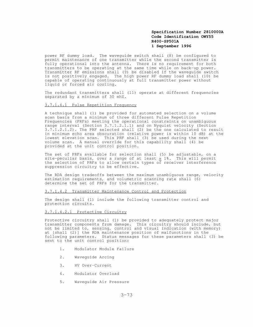
Specification Number 2810000ACode Identification OWY55 R400-SP501A 1 September 1996
3-73
power RF dummy load. The waveguide switch shall (8) be configured topermit maintenance of one transmitter while the second transmitter isfully operational into the antenna. There is no requirement for bothtransmitters to be operating at the same time while on back-up power. Transmitter RF emissions shall (9) be disabled if the waveguide switchis not positively engaged. The high power RF dummy load shall (10) becapable of operating continuously at full transmitter power withoutliquid or forced air cooling.
The redundant transmitters shall (11) operate at different frequenciesseparated by a minimum of 30 mhZ.
3.7.1.4.1 Pulse Repetition Frequency
A technique shall (1) be provided for automated selection on a volumescan basis from a minimum of three different Pulse RepetitionFrequencies (PRFs) meeting the operational constraints on unambiguousrange interval (Section 3.7.1.2.1.1) and on Nyquist velocity (Section3.7.1.2.1.2). The PRF selected shall (2) be the one calculated to resultin minimum echo area obscuration (relative power is within 10 dB) at thelowest elevation scan. This PRF shall (3) be used during the nextvolume scan. A manual override for this capability shall (4) beprovided at the unit control position.
The set of PRFs available for selection shall (5) be adjustable, on asite-peculiar basis, over a range of at least + 1%. This will permitthe selection of PRFs to allow certain types of receiver interferencesuppression circuitry to be effective.
The RDA design tradeoffs between the maximum unambiguous range, velocityestimation requirements, and volumetric scanning rate shall (6)determine the set of PRFs for the transmitter.
3.7.1.4.2 Transmitter Maintenance Control and Protection
The design shall (1) include the following transmitter control andprotection circuits.
3.7.1.4.2.1 Protective Circuitry
Protective circuitry shall (1) be provided to adequately protect majortransmitter components from damage. This circuitry should include, butnot be limited to, sensing, control and visual indication (with memory)at [shall (2)] the RDA maintenance position of malfunctions in thefollowing parameters. Status messages for these parameters shall (3) besent to the unit control position:
1. Modulator Module Failure
2. Waveguide Arcing
3. HV Over-Current
4. Modulator Overload
5. Waveguide Air Pressure

Specification Number 2810000ACode Identification OWY55 R400-SP501A 1 September 1996
3-74
6. Waveguide Air Humidity
7. RF Output Tube Temperature
8. Coolant Flow
9. High Voltage Standing Wave Ratio
3.7.1.4.2.2 Maintenance Controls
Principal maintenance and tuning controls shall (1) be provided on theinterior front panel of the transmitter/modulator so that optimumoperation may be obtained in a minimum of time. The capability shall(2) be provided to manually select the frequency and PRF and to provide[shall (3)] manual control of the RDA for maintenance purposes.
3.7.1.5 Receiver
The receiver unit shall (1) be a stable, sensitive, wide dynamic rangematched filter receiver providing a flexibility to accept a variety ofinterference rejection filters. The receiver characteristics, such asselectivity, spurious responses, image rejection, and local oscillatorradiation, shall (2) be in accordance with specifications insubparagraph 8 of the Manual of Regulations and Procedures for FederalRadio Frequency Management, RSEC Subsection 5.3.3 (Criteria D) forNEXRAD Units operating anywhere in the 2.7-3.0 GHz band. The receivershall (3) also be capable of complying with subparagraphs 9 and 9c,covering field incorporation of provisions to suppress pulsedinterference in NEXRAD Units which operate in high density areas to bedesignated by the Government.
3.7.1.6 Signal Processing Capability
Doppler radar output data shall (1) be processed to provide estimates ofreflectivity, mean radial velocity, and spectrum width. These estimatesshall (2) meet the requirements defined in Section 3.7.1.2. Inaddition, the processor shall (3) be capable of estimating reflectivityand velocity at signal-to-noise ratios down to and including -3 dB. TheZ, V, and W estimates shall (4) be discarded when the correspondingsignal-to-noise ratio (SNR) is less than a set threshold value. Independent threshold values shall (5) be used for the three estimates(Z, V, W) and a separate set of threshold values shall (6) be used foreach scan strategy and each scan rate used. All threshold values shall(6a) be adaptable at the UCP, in increments of 0.5 dB, over a range ofSNR's of at least -10 dB to +10 dB. Outbound radial velocities shall(7) be defined as positive velocities and inbound radial velocitiesshall (7) be defined as negative velocities.
3.7.1.7 Ground Clutter Suppression
The objective of the ground clutter suppression capability is to improvethe measurement of weather return parameters in the presence of clutter. Clutter suppression is defined as the ratio of clutter input to clutteroutput, normalized to filter noise gain.
Clutter suppression performance is described by the improvement in the

Specification Number 2810000ACode Identification OWY55 R400-SP501A 1 September 1996
3-75
ability to measure weather return parameters from a Gaussian randomprocess weather model in the presence of two different clutter models. Clutter model A is a Gaussian random process with a Gaussian spectrumcentered at zero mean velocity. The clutter rms spectrum width is theroot sum square of 0.1 ms-1 plus the rms spectrum width resulting fromthe antenna rotation rate at the lowest two elevation angles. ClutterModel B represents a scattering echo from a point target and consists ofa complex wave form with an amplitude envelope which is an approximationof the two-way antenna pattern.
3.7.1.7.1 Ground Clutter Suppression Requirements
The RDA shall (1) provide ground clutter suppression capability of atleast 30 dB in the reflectivity channel, and shall (2) provide groundclutter suppression capability for the Doppler channels which meets therequirements shown in Table 3-7 for mean radial velocity (V) andspectrum width (W). In areas where the clutter suppression is notapplied, there shall (3) be no degradation in the weather returnparameter measurement accuracy with respect to sections 3.7.1.2.3.1 and3.7.1.2.3.2.
For testing purposes:
1. Ground clutter suppression performance shall (4) be measuredat a nominal frequency of 2.8 GHz.
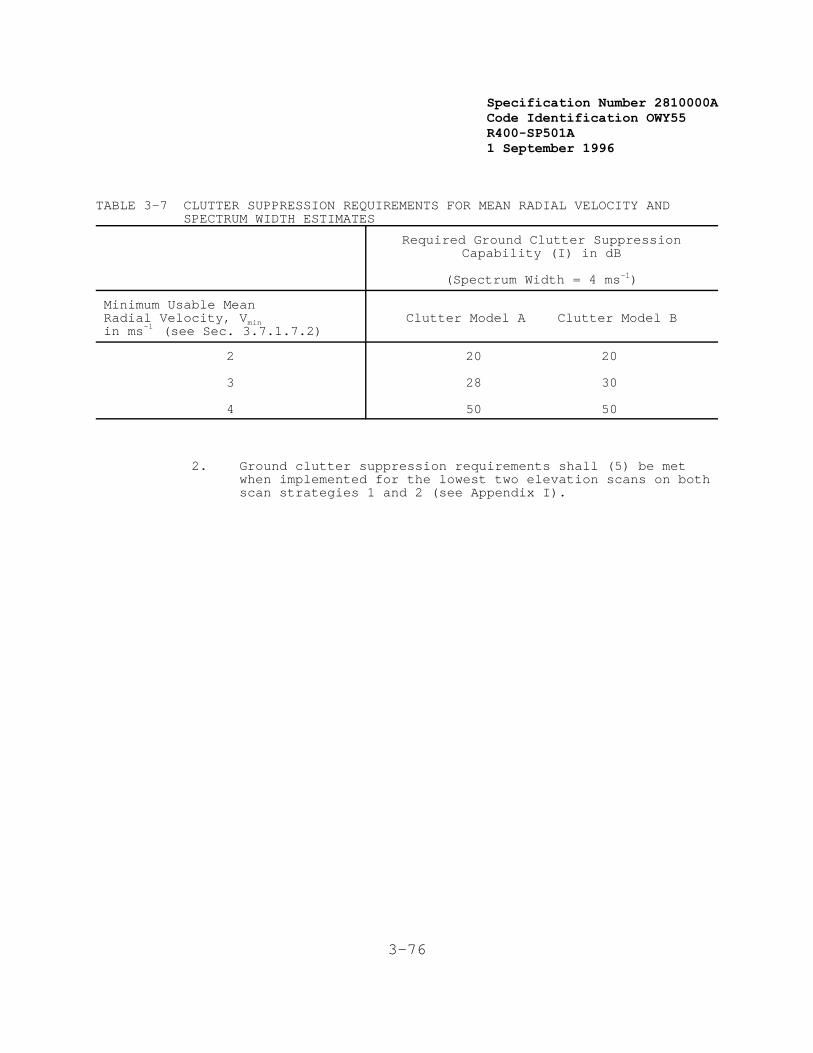
Specification Number 2810000ACode Identification OWY55 R400-SP501A 1 September 1996
3-76
TABLE 3-7 CLUTTER SUPPRESSION REQUIREMENTS FOR MEAN RADIAL VELOCITY AND SPECTRUM WIDTH ESTIMATES
Required Ground Clutter SuppressionCapability (I) in dB
(Spectrum Width = 4 ms-1)
Minimum Usable MeanRadial Velocity, Vminin ms-1 (see Sec. 3.7.1.7.2)
Clutter Model A Clutter Model B
2
3
4
20 20
28 30
50 50
2. Ground clutter suppression requirements shall (5) be metwhen implemented for the lowest two elevation scans on bothscan strategies 1 and 2 (see Appendix I).
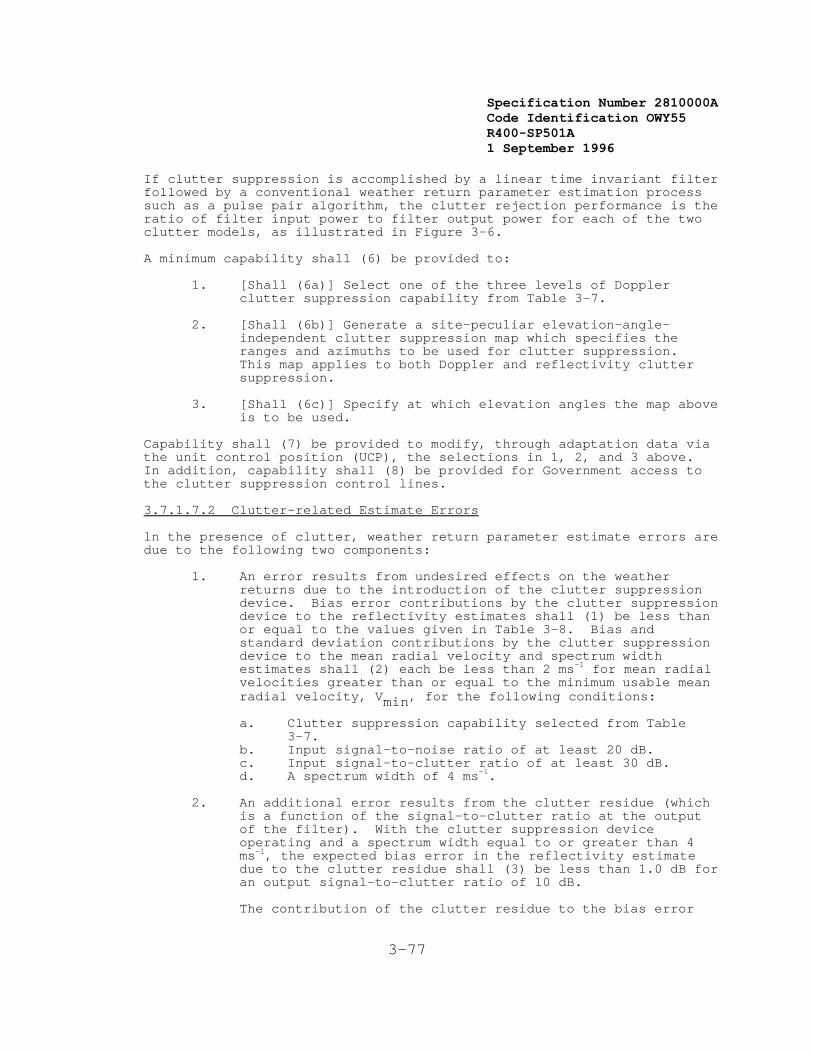
Specification Number 2810000ACode Identification OWY55 R400-SP501A 1 September 1996
3-77
If clutter suppression is accomplished by a linear time invariant filterfollowed by a conventional weather return parameter estimation processsuch as a pulse pair algorithm, the clutter rejection performance is theratio of filter input power to filter output power for each of the twoclutter models, as illustrated in Figure 3-6.
A minimum capability shall (6) be provided to:
1. [Shall (6a)] Select one of the three levels of Dopplerclutter suppression capability from Table 3-7.
2. [Shall (6b)] Generate a site-peculiar elevation-angle-independent clutter suppression map which specifies theranges and azimuths to be used for clutter suppression. This map applies to both Doppler and reflectivity cluttersuppression.
3. [Shall (6c)] Specify at which elevation angles the map aboveis to be used.
Capability shall (7) be provided to modify, through adaptation data viathe unit control position (UCP), the selections in 1, 2, and 3 above. In addition, capability shall (8) be provided for Government access tothe clutter suppression control lines.
3.7.1.7.2 Clutter-related Estimate Errors
ln the presence of clutter, weather return parameter estimate errors aredue to the following two components:
1. An error results from undesired effects on the weatherreturns due to the introduction of the clutter suppressiondevice. Bias error contributions by the clutter suppressiondevice to the reflectivity estimates shall (1) be less thanor equal to the values given in Table 3-8. Bias andstandard deviation contributions by the clutter suppressiondevice to the mean radial velocity and spectrum widthestimates shall (2) each be less than 2 ms-1 for mean radialvelocities greater than or equal to the minimum usable meanradial velocity, Vmin, for the following conditions:
a. Clutter suppression capability selected from Table3-7.
b. Input signal-to-noise ratio of at least 20 dB.c. Input signal-to-clutter ratio of at least 30 dB.d. A spectrum width of 4 ms-1.
2. An additional error results from the clutter residue (whichis a function of the signal-to-clutter ratio at the outputof the filter). With the clutter suppression deviceoperating and a spectrum width equal to or greater than 4ms-1, the expected bias error in the reflectivity estimatedue to the clutter residue shall (3) be less than 1.0 dB foran output signal-to-clutter ratio of 10 dB.
The contribution of the clutter residue to the bias error

Specification Number 2810000ACode Identification OWY55 R400-SP501A 1 September 1996
3-78
for the mean radial velocity estimate shall (4) be equal toor less than 1 ms-1 for the following conditions:
a. Output signal-to-clutter ratio of 11 dB.b. Clutter model A (see Section 3.7.1.7).c. V = (Va/2) (where Va is the Nyquist velocity).d. W = 4 ms-1.
The contribution of the clutter residue to the bias errorfor the spectrum width estimate shall (5) be equal to orless than 1 ms-1 for the following conditions:
a. Output signal-to-clutter ratio of 15 dB.b. Clutter model A.c. V = (Va/2).d. W = 4 ms-1.
3.7.1.8 Control Functions
The RDA shall (1) include all hardware and software necessary foroperational control and monitoring of the RDA functional area.
The RDA control capability shall (2) support performing cold startup,restart, warm startup and control commands. The RDA control capabilityshall (3) also support the running of off-line diagnostics as defined inSection 3.7.6.1.4.
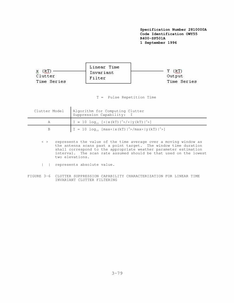
Specification Number 2810000ACode Identification OWY55 R400-SP501A 1 September 1996
3-79
T = Pulse Repetition Time
Clutter Model Algorithm for Computing ClutterSuppression Capability: I
A I = 10 log10 [<|x(kT)|2>/<|y(kT)|2>]
B I = 10 log10 [max<|x(kT)|2>/max<|y(kT)|2>]
< > represents the value of the time average over a moving window asthe antenna scans past a point target. The window time durationshall correspond to the appropriate weather parameter estimationinterval. The scan rate assumed should be that used on the lowesttwo elevations.
| | represents absolute value.
FIGURE 3-6 CLUTTER SUPPRESSION CAPABILITY CHARACTERIZATION FOR LINEAR TIME INVARIANT CLUTTER FILTERING
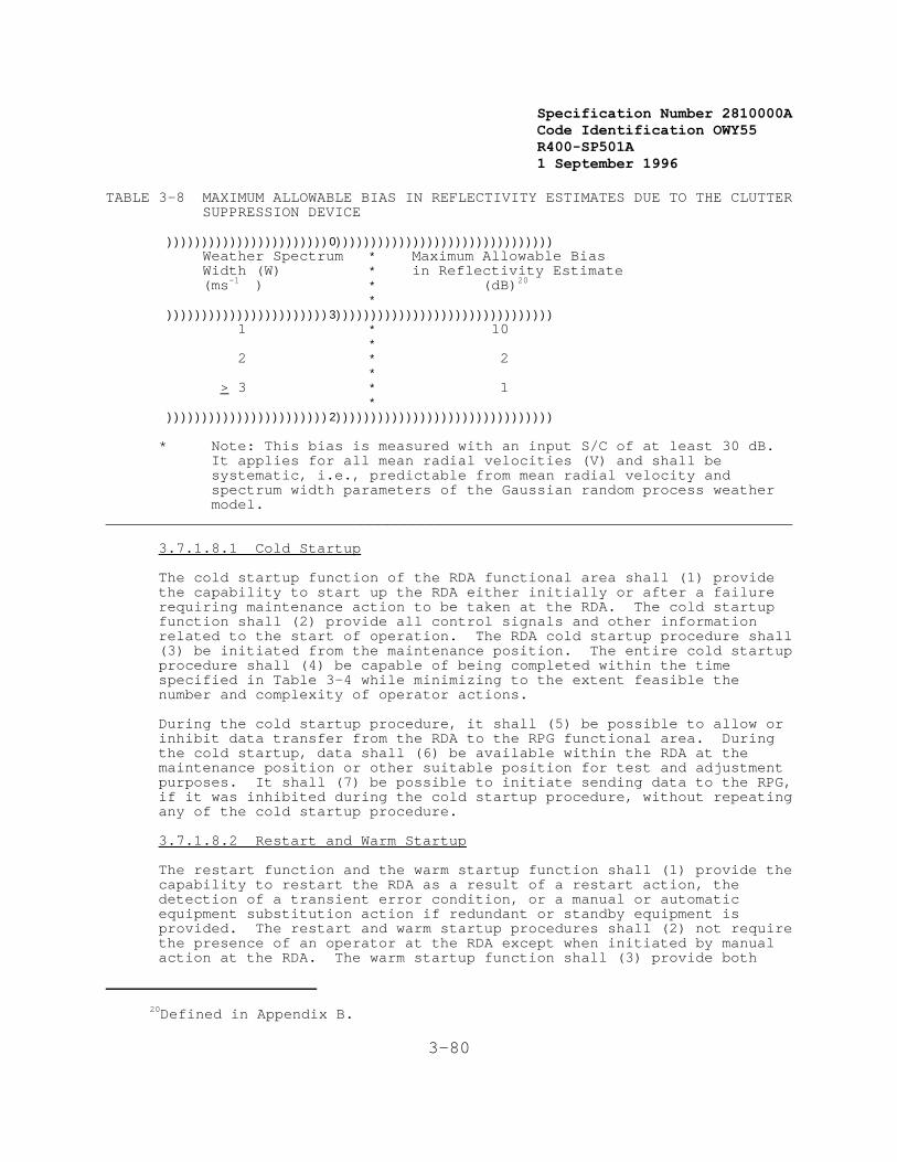
Specification Number 2810000ACode Identification OWY55 R400-SP501A 1 September 1996
20Defined in Appendix B.
3-80
TABLE 3-8 MAXIMUM ALLOWABLE BIAS IN REFLECTIVITY ESTIMATES DUE TO THE CLUTTER SUPPRESSION DEVICE
)))))))))))))))))))))))0))))))))))))))))))))))))))))))) Weather Spectrum * Maximum Allowable Bias Width (W) * in Reflectivity Estimate (ms-1 ) * (dB)20
* )))))))))))))))))))))))3))))))))))))))))))))))))))))))) 1 * 10 * 2 * 2 * > 3 * 1 * )))))))))))))))))))))))2)))))))))))))))))))))))))))))))
* Note: This bias is measured with an input S/C of at least 30 dB. It applies for all mean radial velocities (V) and shall besystematic, i.e., predictable from mean radial velocity andspectrum width parameters of the Gaussian random process weathermodel.
______________________________________________________________________________
3.7.1.8.1 Cold Startup
The cold startup function of the RDA functional area shall (1) providethe capability to start up the RDA either initially or after a failurerequiring maintenance action to be taken at the RDA. The cold startupfunction shall (2) provide all control signals and other informationrelated to the start of operation. The RDA cold startup procedure shall(3) be initiated from the maintenance position. The entire cold startupprocedure shall (4) be capable of being completed within the timespecified in Table 3-4 while minimizing to the extent feasible thenumber and complexity of operator actions.
During the cold startup procedure, it shall (5) be possible to allow orinhibit data transfer from the RDA to the RPG functional area. Duringthe cold startup, data shall (6) be available within the RDA at themaintenance position or other suitable position for test and adjustmentpurposes. It shall (7) be possible to initiate sending data to the RPG,if it was inhibited during the cold startup procedure, without repeatingany of the cold startup procedure.
3.7.1.8.2 Restart and Warm Startup
The restart function and the warm startup function shall (1) provide thecapability to restart the RDA as a result of a restart action, the detection of a transient error condition, or a manual or automaticequipment substitution action if redundant or standby equipment isprovided. The restart and warm startup procedures shall (2) not requirethe presence of an operator at the RDA except when initiated by manualaction at the RDA. The warm startup function shall (3) provide both
Specification Number 2810000ACode Identification OWY55 R400-SP501A 1 September 1996
3-81
local control (RDA) and remote control over startup functions such asantenna rotation startup and transmitter startup. The restart and warmstartup procedures shall (4) be logical subsets of the cold startupprocedure. The restart and warm startup procedures shall (5) be capableof being performed by one person within the time specified in Table 3-4.
An RDA warm startup response time shall (6) be measured from theinitiation of the warm startup control command from the unit controlposition or the RDA maintenance position until the RDA is operational,the RDA to RPG interface is reestablished and valid data transfer to theRPG has begun.
An RDA restart response time shall (7) be measured from the initiationof the restart control command (issued from the unit control position orthe RDA maintenance position) or from the detection of an errorcondition requiring an RDA restart, until the RDA is operational, theRDA to RPG interface is reestablished, and valid data transfer to theRPG has begun. An RDA restart shall (8) include an RDA warm startupprocedure.
3.7.1.8.3 Control Commands
The RDA shall (1) provide control commands for various adjustments,operational conditions, and operational parameters. The controlcommands shall (2) be accepted from both the maintenance positionassociated with the RDA and the unit control position (see Section3.7.2.5).
At a minimum, control commands shall (3) be provided for the followingfunctions:
1. RDA Shutdown. This command shall (4) provide an orderly,controlled, manually initiated shutdown of the RDA to astate from which a warm startup may be performed.
2. RDA Warm Startup. This command shall (5) provide thecapability to resume the RDA operation from the warmstartup state.
3. RDA Restart. This command shall (6) provide the capabilityto initiate an RDA restart from the unit control position.
4. Stop/Start Data Transmission. This command shall (7)provide the capability to start or stop the transmission ofbase data from the RDA to the RPG. Parameters of thiscommand shall (8) allow selection of the reflectivity, meanradial velocity, and spectrum width data.
5. Set RDA Mode Control. This command shall (9) provide forchanging RDA Modes by selecting various RDA parameter sets. The parameter sets which may be selected are the following:
a. Mode Control: Operational/Maintenance
b. Operational Modes: A, B, and others specified in
Specification Number 2810000ACode Identification OWY55 R400-SP501A 1 September 1996
3-82
Appendix I
6. Readout Status Parameters. This command shall (10) providethe capability to output selected or all RDA parameters tothe requesting maintenance or unit control position.
3.7.1.9 Monitoring and Error Detection Capability
The RDA shall (1) include a capability for equipment monitoring andreporting the status of radar functions to the RDA maintenance positionand the unit control position. This capability shall (2) provide theRPG and PUP with RDA status, including a positive indication that theRDA is operating within all specification parameters. The RDA equipmentshall (3) include built-in test equipment to provide a combination ofon-line and off-line status monitoring and self test to support systemoperation and fault isolation to the degree required to meet the systemmaintainability and availability requirements.
The RDA shall (4) include the capability of monitoring the performanceof selected functions on a noninterfering basis with the processing ofon-line data and perform sufficient tests to ascertain that nodegradation in operation has occurred. The following are typical of theparameters required to be monitored (a complete list will be dependenton the RDA equipment proposed):
1. Average Transmitter Power (at feed horn)
2. Receiver Sensitivity and Gain
3. Waveguide Arcing
4. Pulse Repetition Frequency
5. Memory Checks
6. Signal Processor Performance
7. A/D Converter Performance
8. Timing Controls
9. Over/Under Voltages
10. Over/Under Currents
11. Over Temperature
12. Air Flow Failures
13. Pedestal Oil Level
14. Radar Data Output
15. Backup Power
If appropriate, an Overload Warning Threshold adaptation parameter shall
Specification Number 2810000ACode Identification OWY55 R400-SP501A 1 September 1996
3-83
(5) define the utilization level that, when reached or exceeded, willresult in an overload warning being issued. Typical overload typesinclude processor, memory, communication interfaces, input data buffers,mass storage, and archival storage utilizations.
If appropriate, a Task Overload Shedding Priority adaptation parametershall (6) define the order for deleting (not performing) processingtasks when an overload situation occurs. Processing tasks shall (7) bereactivated following elimination of the overload condition in thereverse of the shedding order. Task reactivation shall (8) be performedin a manner so as not to allow a rapid cycling between overload andnon-overload conditions.
Alarms shall (9) be provided for RDA conditions which might result infurther equipment problems or failures if the indicated condition is notcorrected. This shall (10) include the case when the automatic radarcalibration function can no longer maintain performance parameterswithin specification limits. All alarms shall (11) drive indicators onindividual units, where appropriate, and at the maintenance position inthe RDA, and shall (12) result in alarm messages being sent to the unitcontrol position, with further dissemination as defined in Section3.7.2.6.
3.7.1.10 Display Functions
The RDA shall include a capability to display radar data for purposes ofsystem monitoring, maintenance, and adjustment. The design shallinclude displays, meters, and indicators as necessary for maintenance.
3.7.1.11 Calibration
The RDA shall (1), during each volumetric scan sequence, automaticallyperform the calibration measurements defined in this section andautomatically correct the base data. The calibration data andparameters shall (2) accompany products for applications by the users atall levels of data processing. A manual override of the automaticcalibration shall (3) be provided from both the RDA maintenance positionand from the unit control position.
The quantitative measures of RDA performance shall (4) be incorporatedinto the digital information provided to the unit control position andshall (5) be available as a visual indicator at the RDA maintenanceposition. The calibration measurements which shall (6) be included arethe following:
1. [Shall (6a)] A measurement of the average transmitted powerlevel.
2. [Shall (6b)] A calibration of the RDA reflectivity channelfrom the channel's first active device through the signalprocessor. This calibration shall (7) be timed tocorrespond to regions of space devoid of both ground clutterand weather echoes. The calibration shall (8) be performedover at least two widely spaced received power levels, andthe calibration signals shall (9) undergo the same averagingas the weather echoes.

Specification Number 2810000ACode Identification OWY55 R400-SP501A 1 September 1996
3-84
3. The mean radial velocity and spectrum width processingperformance shall (10) be monitored. This monitoringfunction shall (11) be timed to correspond to regions ofspace devoid of both ground clutter and weather echoes, andshall (12) include at least one known value of mean radialvelocity and spectrum width at one range cell.
3.7.1.12 Set-up Mode
The RDA shall (1) include the capability to measure and monitor thefollowing parameters:
1. [Shall (1a)] Transmitter frequency
2. [Shall (1b)] Peak transmitted power
3. [Shall (1c)] Transmitted pulse shape
4. [Shall (1d)] Transmitted pulse width
5. [Shall (1e)] Pulse repetition interval
6. [Shall (1f)] Receiver calibration over entire dynamic range
7. [Shall (1g)] Mean radial velocity and spectrum widthcomputation over entire Nyquist interval
8. [Shall (1h)] Complex spectrum in at least one range cellthat is controllable over the entire system PRF with thenumber of samples being variable from 32 to 512 in power of2 increments.
3.7.1.13 Archiving Interface Connections
The RDA shall (1) provide interface connections to allow archive data tobe obtained. The Archive I data shall (2) be the output of the receiver(analog time-domain data). The Archive II data shall (3) be the outputof the signal processor (digital base data and status information). Synchronization, calibration, and other data required to properlyinterpret the archive data, including date, time, antenna position,status, etc., shall (4) be available at the Archive I and Archive IIinterface connections.
3.7.1.13.1 Archive II Equipment
All of the hardware and software necessary to perform the Archive IIfunction including a permanent and easily transportablerecording/archiving medium shall (1) be provided. The RDA shall (2)also have the capability to ingest, from the archive system, datapreviously archived by any RDA. One individual physical archive packageshall (3) be capable of storing at least 3 hours worth of real time basedata and related information using the A1 scan strategy. Starting andstopping of the Archive II equipment shall (4) be controllable from the UCP. The Archive II equipment shall (5) be packaged in a stand-aloneequipment rack or chassis.

Specification Number 2810000ACode Identification OWY55 R400-SP501A 1 September 1996
3-85

Specification Number 2810000ACode Identification OWY55 R400-SP501A 1 September 1996
3-86
3.7.1.14 Base Data Interface
The RDA shall (1) provide for one interface for the purpose of providingreal-time base data to a user site. This interface shall (2) beindependent of any interface needed for transmission of base data to anRPG.

Specification Number 2810000ACode Identification OWY55 R400-SP501A 1 September 1996
3-87
RADAR PRODUCT GENERATION (RPG)SEGMENT
Specification Number 2810000ACode Identification OWY55 R400-SP501A 1 September 1996
3-88
3.7.2 Radar Product Generation Functional Area
The Radar Product Generation (RPG) functional area uses base datareceived from the Radar Data Acquisition (RDA) functional area (eitherdirectly or via the Communications functional area) to generate a set ofproducts which contains information concerning the followingmeteorological phenomena:
1. Precipitation
2. Wind and Wind Shear
3. Tornadoes
4. Fronts and Fine Lines
5. Tropical Cyclones
6. Mesocyclones
7. Thunderstorms
8. Turbulence
9. Icing Conditions
10. Hail
11. Freezing/Melting Level
The products are then distributed to the Principal User Processing (PUP)functional area and to other users.
The RPG shall (1) be capable of accepting, storing, and processing datafor differing numbers of elevation scans and scan rates including 14elevation scans from zero degrees to +20 degrees in a volume scan timeof five minutes.
The RPG shall (2) provide for one interface for real-time distributionof base data to a user site. The specification of this interface isleft to the contractor.
It shall (3) be possible to perform RPG functions in either a fullyautomated or a manually aided mode. In a fully automated mode the RPGshall (4) be capable of being operated unmanned. Any performancelimitations associated with a fully automated operation shall (5) besubject to Government approval.
The RPG functional area comprises the following capabilities:
1. Product Generation
2. Product Storage
3. Product Distribution
Specification Number 2810000ACode Identification OWY55 R400-SP501A 1 September 1996
21Defined in Appendix B.
3-89
4. Display and Data Entry
5. Control
6. Status Monitoring and Error Detection
7. Archiving
8. Hydrometeorological Processing
9. Alert Processing
The hardware to implement capabilities 4, 7, and 8 may not be providedat all sites. Tables and/or equipment stands shall (6) be provided tosupport all display, data entry, and control equipment.
3.7.2.1 Product Generation
Base data shall (1) be used to detect and measure meteorologicalphenomena based on Government supplied algorithms. The algorithms aredefined in Appendix C.
Government supplied algorithms shall (2) be implemented in an easilychangeable manner, based on a system design to be specified.
The RPG shall (3) produce the following types of products21:
1. Base Products
2. Derived Products
3. Alphanumeric Products
4. Derived Data Arrays
The products are defined in Appendix E.
Each product shall (4) include the data observation time or integrationperiod; the date and time at which it was generated; and the elevationangle, azimuth, geographic area, resolution information, and othermeteorological annotation data as appropriate to the generated product. Products shall (5) be generated such that they can be displayed eitherwith or without the meteorological annotation data. All times displayedor included in products shall (6) be expressed as Greenwich Mean Time(GMT). All distances to be numerically displayed or included inproducts shall (7) be expressed in nautical miles, all altitudes infeet, and all speeds in knots.
Presentation of base products and derived products to operationalpersonnel assumes the use of a color graphic display. Presentation of alphanumeric products does not require this capability.
Specification Number 2810000ACode Identification OWY55 R400-SP501A 1 September 1996
3-90
3.7.2.1.1 Base Products
Base products shall (1) provide reflectivity estimates for eachelevation angle to a range of 460 km. Base products shall (2) providemean radial velocity and spectrum width estimates for each elevationangle to a range of 230 km. The highest resolution provided in a baseproduct shall (3) be equal to the resolution available from the basedata.
These products shall (4) be displayed as a vertical projection onto theearth's surface, e.g., 100 km at 20o will be displayed at approximately94 km. For a given coverage area (see Table E-1), each elevation scanshall (5) be displayed at the same geographic scale relative to theearth's surface.
A technique shall (6) be provided to present the mean radial velocityand spectrum width data at the correct range (range unfolding). Datasignificantly contaminated due to overlaid weather echoes or groundclutter shall (7) be identified.
3.7.2.1.2 Derived Products
Derived products shall (1) provide users with access to large volumesand varieties of data in easily displayable formats. These largevolumes of data shall (2) be concentrated into easily interpretableproducts which may include annotations (added either automatically as aresult of an algorithm, or manually) to identify specific meteorologicalphenomena. The annotations, which include alphanumeric data, special symbol dataand line segments, shall (3) be nondestructive of the data and shall (4)remain a part of the product unless they are removed by manual action.
Products not requiring manual annotations shall (5) not be delayed by amanual annotation function which may be required for other products. Derived products may also be used for further processing by a user.
3.7.2.1.3 Alphanumeric Products
Alphanumeric products shall (1) provide weather information in a formsuitable for display on both graphic and alphanumeric display devices. This information shall (2) include alert messages, summary data, andfree text messages.
3.7.2.1.4 Derived Data Array Products
Derived data array products shall (1) provide information in a formsuitable for transmission to and processing in a system external to theNEXRAD System. These products are not in a displayable format.
3.7.2.2 Product Storage
The RPG shall (1) provide the capability for on-line storage of allproducts. The RPG shall (2) provide the capability for defining andchanging the product mix and retention time (up to a maximum of sixhours) for products to be retained in the on-line RPG storage. Thiscapability shall (3) be controlled by input from the unit control
Specification Number 2810000ACode Identification OWY55 R400-SP501A 1 September 1996
3-91
position by means of adaptation data. Products stored within the RPGon-line storage shall (4) not be capable of being altered from a PUP,nor by input from any principal user or other user interface.
The RPG on-line storage of products shall (5) be capable of storing for1.5 hours the full load product mix (excluding Derived Data Arrays)defined in Table E-1.
3.7.2.3 Product Distribution
Each RPG shall (1) make products available for distribution to theprincipal and other users, including the following:
1. Associated PUPs.
2. Non-associated PUPs.
3. FAA ARTCCs for which the RDA provides coverage.
4. NWS RFCs for which the RDA provides coverage.
5. Other users.
6. Principal User External Systems.
The number of sites to which an RPG must be capable of distributingproducts shall (2) be limited only by the limits shown in Para.3.7.2.5.13.
3.7.2.3.1 Distribution to an Associated PUP
For each associated PUP, the RPG shall (1) provide those productsrequested by the PUP, including both products to be sent on a routinebasis and products requested on a one-time basis. Products generatedbecause alert criteria were met shall (2) be transmitted to therequesting operational position prior to all other products defined fortransmission to that operational position. Different associated PUPsmay request different product sets for routine receipt from an RPG. Thedistribution of products shall (3) satisfy the users' frequency andpriority requirements within the constraints of available communicationsbandwidth. All products stored on-line within the RPG shall (4) beavailable to any associated PUP. Any product which has not beengenerated prior to the receipt of a request (e.g., cross section) shall(5) be generated and distributed. The RPG shall (6) support on-linerequests for changes and additions to the set of products routinely sentto an associated PUP. It shall (7) also support on-line changes totheir frequency or priority.
3.7.2.3.2 Distribution to Non-associated PUPs
Each RPG shall (1) be capable of providing products to any PUP inresponse to a one-time request (i.e., dial-up) from the PUP. Thespecific products available for distribution to non-associated PUPsshall (2) be controlled by adaptation data.
3.7.2.3.3 Distribution to FAA ARTCCs
Specification Number 2810000ACode Identification OWY55 R400-SP501A 1 September 1996
3-92
Each RPG shall (1) provide products on a routine basis to those ARTCCsselected by the FAA, referred to herein as associated ARTCCs. Differentassociated ARTCCs may request different product sets for routine receiptfrom a particular RPG. Each RPG shall (2) also provide any ARTCC withproducts it has requested on a one-time basis. All products availablefor distribution to associated PUPs (see Section 3.7.2.3.1) shall (3)also be available for distribution to associated ARTCCs. Thedistribution of products to ARTCCs shall (4) satisfy the FAA's frequencyand priority requirements within the constraint of availablecommunications bandwidth. The RPG shall (5a) also support on-linerequests for changes and additions to the set of products routinely sentto an associated ARTCC, and to their frequency and priority [Shall(5b)].
3.7.2.3.4 Distribution to NWS RFCs
The RPG shall (1) provide derived data array precipitation products tothe RFC for which that RDA provides coverage within the RFC's area ofresponsibility. Each RFC may choose products from any RPG within itsarea of responsibility via dial-up requests.
3.7.2.3.5 Distribution to Other Users
Each RPG shall (1) be capable of providing selected products to otherusers. The capability shall (2) be provided at the UCP to independentlyselect the distribution method to be used for each Class IV port at theRPG. The available distribution methods shall (3) include as a minimum: a single set of products, single product(s) repeatedly transmitted, andselection from a limited menu of products entered at the UCP.
3.7.2.3.6 Distribution to Principal User External Systems
Each RPG shall (1) be capable of providing products controlled byadaptation data to external systems of the principal users.
3.7.2.4 Operational Position Capabilities
For selected NEXRAD Units, the RPG shall (1) include a collocatedoperational position. The RPG operational position shall (2) includethe same display, data entry, and hard copy equipment and provide thesame functional capabilities as defined in Sections 3.7.3.1 through3.7.3.8.
The interface from an RPG to an RPGOP shall (3) exchange data at no lessthan 56,000 bits per second, full duplex. The RPGOP shall (4) employthe RS422 implementation of the RS449 standard communications interfacefor Class I lines. In all other respects, this interface shall (5)conform to the requirements specified for Class I lines in Appendix A,NEXRAD Interface Control Document.
3.7.2.5 Control Capabilities
Control capabilities shall (1) provide for operation of the NEXRAD Unit.These include:
Specification Number 2810000ACode Identification OWY55 R400-SP501A 1 September 1996
3-93
1. RPG Startup
2. RPG Restart
3. RDA Restart and Warm Startup
4. User Interface Establishment
5. Controlled Shutdown
6. RDA Mode Control
7. Manual Reconfiguration
8. Archiving Control
9. Product Generation Control
10. Product Storage Control
11. Adaptation Control
12. Backup Power Control
13. Communication Line Configuration
14. Redundant Channel Control
15. Other User Distribution
To perform the control functions, a unit control position which containssuitable display and data entry equipment shall (2) be provided. Control commands entered from this equipment shall (3) be executedwithin the RPG. Provisions shall (4) be made to limit the access toselected classes of control functions through passwords or othersuitable means as approved by the Government. At least two levels ofprotection shall (5) be provided. The unit control position shall (6)be capable of being located remotely from the remaining RPG equipmentvia a dedicated communications line.
The dedicated communications line to a remotely located unit controlposition shall (7) have a data rate of no less than 4800 bits per secondand shall (8) have a Government approved protocol or equipment whichshall (9) contain error detection/correction capability to ensurereliable transmission of commands and status information. Errordetection capability similar to the LAPB polynomial is consideredminimally acceptable. This interface is not required to fall into anyof the five defined NEXRAD communication classes.
No combination of errors in operator input shall (10) require a restart(see Section 3.7.2.5.2) for recovery. Invalid commands shall (11)result in an appropriate English language error message being providedat the unit control position.
3.7.2.5.1 RPG Startup

Specification Number 2810000ACode Identification OWY55 R400-SP501A 1 September 1996
22Defined in Appendix B. (See Catastrophic Failures)
3-94
An RPG startup capability shall (1) be provided to initiate theoperation of the RPG without any concern for the current state of theremainder of the NEXRAD Unit. RPG startup shall (2) be used to initiateRPG operation when the NEXRAD Unit is first put into operation or afterthe RPG has been down for an extended period (greater than one hour). It shall (3) also be used after system failures which make it impossibleto recover any data present at the time of the failure. RPG startupshall (4) also be used when the RPG restart function (see Section3.7.2.5.2) fails to operate properly.
RPG startup shall (5) be accomplished within the time specified in Table3-4.
During RPG startup it shall (6) be possible to specify either a testmode or an operational mode of operation. In the test mode, data fromthe RDA shall (7) be presented at the operational position (if one isprovided as part of the RPG) for test and monitoring purposes. However,in the test mode, operational data shall (8) not be forwarded to a PUPor any other user. Changing from the test mode to the operational modeshall (9) be possible without repeating the full RPG startup procedure.
The RPG startup capabilities shall (10) include:
1. [Shall (10a)] Initialization of RPG equipment, firmware, andsoftware.
2. [Shall (10b)] Initialization of all clocks and internaltimers.
3. [Shall (10c)] Establishing of the interface with the RDA (ifoperating).
4. [Shall (10d)] Verification of the configuration.
When entering the operational mode, the following capabilities shall(11) also be provided:
1. Establishing interfaces with all applicable principal users.
2. Verification of the operational mode configuration.
3. Notification to principal users that the system isavailable.
3.7.2.5.2 RPG Restart
An RPG restart capability shall (1) be provided to restore the previousstate of the RPG after a failure from which recovery is possible withoutmaintenance action. RPG restart shall (2) also be capable of beingperformed automatically. RPG restart shall (3) be performed when theRPG experiences non-catastrophic failures,22 power interruptions of lessthan one minute, and other such failures.
Specification Number 2810000ACode Identification OWY55 R400-SP501A 1 September 1996
3-95
An RPG restart shall (4) be accomplished within the time specified inTable 3-4 (except for the initiation action in the case of a manuallyinitiated RPG restart).
The RPG restart capabilities shall (5) include:
1. [Shall (5a)] Automatic reboot of the system software (ifnecessary).
2. [Shall (5b)] Restoration to the operating state (e.g., scanmode, product menus, adaptation data, etc.) existing whenservice was interrupted.
3. [Shall (5c)] Re-initialization of all clocks and internaltimers.
4. [Shall (5d)] Reestablishing of the interface with the RDA(if operating).
5. [Shall (5e)] Reestablishing of interfaces with allapplicable users.
6. [Shall (5f)] Verification of the configuration.
7. [Shall (5g)] Notification to the users that the system isagain available.
8. [Shall (5h)] Notification to users of potentially degradeddata.
3.7.2.5.3 RDA Restart and Warm Startup
An RDA restart and warm startup capability shall (1) be provided. Itshall (2) include those restart and warm startup functions defined inSection 3.7.1.8.2 which can be performed at a location remote from theRDA. It shall (3) also include reestablishing of the interface of theRPG with its RDA.
3.7.2.5.4 User Interface Establishment
The capability shall (1) be provided to establish (or reestablish) anydedicated RPG interface with an associated PUP or ARTCC.
3.7.2.5.5 Controlled Shutdown
The capability shall (1) be provided to shut down in a controlled mannerthe following parts of the system:
1. The RDA, including the RDA interface.
2. The communications links with one or more PUPs, PUESs, orother users.
3. The RPG.
A controlled shutdown of the RDA shall (2) return it to a state from
Specification Number 2810000ACode Identification OWY55 R400-SP501A 1 September 1996
3-96
which an RDA warm startup may be performed. It shall (3) terminate thereceipt by the RPG of radar data from the RDA. A controlled shutdown ofthe RDA shall (4) also result in notification of associated PUPs andother users of the shutdown, but shall (5) not affect systemcapabilities related to sending existing products to the users.
The controlled shutdown of a user interface (e.g., one with anassociated PUP) shall (6) not affect the ability of the user to operateusing previously provided products, nor shall (7) it affect otherinterfaces.
The controlled shutdown of the RPG shall (8) include the controlledshutdown of the RDA to a state from which an RDA warm startup may beperformed, the controlled shutdown of all user interfaces, and thereturn of the RPG to a condition from which an RPG startup is requiredto resume operation.
3.7.2.5.6 RDA Mode Control
The capability shall (1) be provided to change parameters of the RDA. This shall (1) include all parameters defined in Section 3.7.1.8.3.
3.7.2.5.7 Manual Reconfiguration
The capability shall (1) be provided to manually reconfigure RPGequipment.
3.7.2.5.8 Archiving Control
The capability shall (1) be provided to activate or deactivate thearchiving function, and to select the product types to be routinelyarchived and their frequency of archiving. The capability shall (2)also be provided to select products stored within the RPG for archivingon a one-time basis.
3.7.2.5.9 Product Generation Control
The capability shall (1) be provided to select the set of products to beroutinely generated. Routine products are those that have been selectedfor routine receipt by any associated PUP or the RPG operationalposition. In addition, the capability shall (2) be provided to specify,on a per product basis, the frequency at which the product is generated.
The RPG shall (3) be capable of generating one product for each of thealert categories (See Appendix J) for which alert conditions are met inany of the operators' selected alert areas. The product shall (4) beautomatically sent to the associated operational position(s) whose alertareas are affected and who have requested the automatic product. Theproduct selected for generation for each alert category shall (5) be anadaptable parameter at the RPG.
The RPG shall (6) generate products in response to one-time productrequests even when: a) parameter values for meteorological phenomenahave not been met, and when: b) the product has not been selected forroutine generation.

Specification Number 2810000ACode Identification OWY55 R400-SP501A 1 September 1996
3-97
3.7.2.5.10 Product Storage Control
The capability shall (1) be provided to select or change the set ofproduct types to be stored in the on-line storage. In addition, thecapability shall (2) be provided to specify, on a per product basis, thefrequency at which the product is stored and the storage time period(maximum of 6 hours).
3.7.2.5.11 Adaptation Control
The capability shall (1) be provided to select or change additionaladaptation parameter values. Examples of parameters which are adaptableare described in Appendix H.
3.7.2.5.12 Backup Power Control
The capability shall (1) be provided to initiate switchover betweencommercial and backup power for all NEXRAD equipment located at theRadar site.
3.7.2.5.13 Communication Line Configuration
It shall (1) be possible to configure or reconfigure any narrowbandcommunication port to connect to and communicate with any of the NEXRAD communication classes available. This configuration shall (2) beaccomplished solely via adaptation data and with the installation of theproper operating system and communications equipment. The maximumnumber of ports (based on 9.6 kbps/port) is limited by the RPG aggregatedata rate of 288 kbps, expandable to at least 441.6 kbps. The maximumnumber of ports and the number of ports that may be configured for eachclass shall (3) be provided as shown below:
Ports Unexpanded Limits Expanded Limits
Maximum 30 46
Class 1 25 40
Class 2 25 40
Class 3 4 4
Class 4 4 4
Class 5 2 2
3.7.2.5.14 Redundant Channel Control
The capability to control the state (standby or operation) of the FAAredundant channels of 3.2.1.5.1 shall (1) be provided. The capabilityto control the state (full off, standby, or operation) of the NWSredundant channels of 3.2.1.5.2 shall (2) be provided.
3.7.2.5.15 Other User Distribution
It shall (1) be possible to select the method of product distribution
Specification Number 2810000ACode Identification OWY55 R400-SP501A 1 September 1996
3-98
for each Class IV port. The possible methods shall (2) be as requiredby Specification 3.7.2.3.5.
3.7.2.6 Status Monitoring and Error Detection
The capability shall (1) be provided at the unit control position tomonitor the status of the RDA, the RPG, the associated PUPs, and eachcommunications interface. This status monitoring capability shall (2) include operational modes, conditions, and parameters, as well as error conditions. Alarm messages received by the unit control position shall(3) be considered status messages for the purposes of furtherdissemination. A descriptive English language message shall (4) beprovided at the unit control position: (a) when requested at the unitcontrol position; (b) periodically, as specified at the unit controlposition; and (c) when there is a change in the status of the RDA, theRPG, an associated PUP, or any of the NEXRAD Unit communicationsinterfaces.
A descriptive English language message shall (5) be provided at theassociated PUPs and ARTCC: (a) when requested, (b) periodically asspecified at the PUPs or ARTCC, and (c) when there is a change in thestatus of the RDA or RPG.
The capability shall (6) be provided to detect and record all statusmessages and hardware and software errors. A descriptive Englishlanguage message shall (7) be provided to the unit control position anda permanent record of the message shall (7A) be kept. A capability toadd a hardcopy device for the recording of all status and error messagesshall (8) be provided.
The capability shall (9) be provided at the unit control position toturn on or turn off status monitoring and error detection messages. This capability shall (10) be provided individually for the RPG itself,each of its configuration items, the interfacing RDA, each associatedPUP, and each of its communications interfaces.
An Overload Warning Threshold adaptation parameter shall (11) define theutilization level that, when reached or exceeded, will result in anoverload warning being issued. Overload types include as a minimum:processor, memory, communication interfaces, input data buffers, massstorage, and archival storage utilizations.
A Task Overload Shedding Priority adaptation parameter shall (12) definethe order for deleting (not performing) processing tasks when anoverload situation occurs.
Processing tasks shall (13) be reactivated following elimination of theoverload condition in the reverse of the shedding order. Task reactivation shall (14) be performed in a manner so as not to allow arapid cycling between an overload and non-overload condition to occur.
A Product Overload Shedding/Recovery Priority adaptation parameter shall(15) define the order for deleting products when an overload situationoccurs on an interface between functional areas, or an interface betweena functional area and an external user's system. The recovery from anoverload condition shall (16) be performed automatically as soon as

Specification Number 2810000ACode Identification OWY55 R400-SP501A 1 September 1996
3-99
conditions allow. Products shall (17) be recovered in the reverse ofthe shedding order.
3.7.2.7 Archiving
The capability shall (1) be provided within the RPG to generate thearchive record of background maps and selected products, on a permanentand easily transportable medium. This is defined as Archive III. TheRPG shall (2) have the capability to ingest, from the archive medium,products previously archived by any RPG or PUP for processing ordisplay. The capability shall (3) be provided to display archived RPGor PUP status messages on the UCP. The individual physical archivemedium shall be capable of storing at least 168 hours worth of the fullload archiving product mix as defined in Table E-1. Selection ofproduct types to be archived and the frequency of archiving shall (4) bemade by manual action from the Unit Control Position, as discussed inSection 3.7.2.5.8. The capability shall (5) be provided to selectcontinuous status message archiving.
3.7.2.8 Hydrometeorological Processing
Real-time quantitative rainfall estimates shall (1) be generated andmade available for flash flood warning and to prepare rainfall-relatedproducts for transmission to WSOs, WSFOs and RFCs.
Hydrometeorological processing requires rain gage data for qualitycontrol of rainfall estimates. Based on Government-supplied criteria asdefined by the Precipitation Detection Function in Appendix D, a NEXRADUnit shall (2) initiate collection of rain gage data by calling not morethan two Rain Gage Data Acquisition Computers. The data will be sent tothe NEXRAD Unit once per hour by each Rain Gage Data AcquisitionComputer which was initially called.
The number of telemetered rain gages available per radar will not exceed50, distributed over the surveillance area. Data from a maximum of 30gages shall (3) be used for quality control of the processing. If morethan 30 gages received rain during the previous hour, Government-supplied criteria, as defined by the Rain Gage Data Acquisition Functionin Appendix D, shall (4) be used to select the rain gages to providedata for the processing.
3.7.2.9 Alert Processing
The RPG shall (1) generate alert outputs based upon identifiedmeteorological phenomena occurring or projected to occur in alert areasdefined by each associated operational position. Each alert area shall(2) be definable within the range of coverage (See Appendix J) on a griddivided into squares of no larger than 16 X 16 km.
The RPG shall (3) be capable of generating alerts for all categories ofphenomena identified in Appendix J. The categories of Group "a." areones that have different data for each grid square. The coarsestresolution product available may be used to generate these data. Thecategories of Group "b." are based on volume data and use the algorithmoutputs. The categories of Group "c." are a subset of "b." but shall(4) alert based on levels or phenomena projected to occur in an alert

Specification Number 2810000ACode Identification OWY55 R400-SP501A 1 September 1996
3-100
area according to the forecast motion of the storm centroid(s). Foreach alert area, the operator may choose up to 10 categories to alerton.
There shall (5) be one set of thresholding criteria for each alertcategory as outlined in Appendix J. The values used in the thresholdingcriteria shall (6) be part of the adaptation data. All criteria shall(7) be set up as greater than or equal to the value selected. When analert condition has been detected, an alert message shall (8) betransmitted to the appropriate operational position(s). The alertmessage shall (9) contain the alert area location and a briefdescription of the alert criteria. For those alerts that are stormrelated (i.e., Groups b and c, Appendix J, except for VAD and rainfallaccumulation) the storm ID shall (10) also be provided.
The capability for additional categories shall (11) be provided in theamounts listed in Appendix J.
Specification Number 2810000ACode Identification OWY55 R400-SP501A 1 September 1996
3-101
PRINCIPAL USER PROCESSING (PUP)SEGMENT
Specification Number 2810000ACode Identification OWY55 R400-SP501A 1 September 1996
3-102
3.7.3 Principal User Processing Functional Area
The Principal User Processing (PUP) functional area shall (1) providethe products of a NEXRAD Unit to its principal users based oninformation received from the RPG functional area.
The PUP functional area includes display and data entry equipment whichshall (2) provide the capabilities as specified in Section 3.7.3.1. Italso includes the following functional capabilities as specified inSections 3.7.3.2 through 3.7.3.8, respectively:
1. Product Request
2. Product Display
3. Local Product Storage
4. Product Annotation and Distribution
5. PUP Control
6. Status Monitoring
7. Archiving
3.7.3.1 PUP Display and Data Entry
Each PUP shall (1) include two color graphic displays, an alphanumericdisplay, data entry equipment, and hard copy capability. Worktablesand/or equipment stands shall (2) be provided to support this equipment. The PUP primary operator's chair shall (3) also be provided. Atselected locations it shall (4) be possible to locate the display anddata entry equipment at a maximum of 300 cable feet from the PUPprocessing equipment, while maintaining full functionality.
3.7.3.1.1 Color Graphic Displays
Each color graphic display provided as part of the PUP configurationshall (1) be a raster scan, 60 Hz, non-interlaced unit with a diagonaldimension of at least 19 inches, and a resolution of at least 640 x 512(horizontal x vertical) picture elements (pixels).
It shall (2) be possible to simultaneously display eight differentluminance values of any of the primary colors (i.e. red, green, blue). Each luminance value, as measured on the display screen, shall (3) be atleast 10% (of the highest luminance value of the primary color beingdisplayed) different from any other luminance value.
It shall (4) also be possible to select and simultaneously display atleast 128 different colors. These colors shall (5) be selected from theset that results from combining the primary color luminance valuesdefined in the preceding paragraph.
Each color graphic display shall (8) be capable of displaying either asingle 512 x 512 pixel product, or up to four 256 x 256 pixel products. When multiple products are simultaneously displayed, it shall (9) be

Specification Number 2810000ACode Identification OWY55 R400-SP501A 1 September 1996
3-103
possible to update, annotate, or replace a single product or change itsbackground map without affecting the display of any other products whichare simultaneously being displayed.
Each color graphic display shall (10) be capable of supporting theproduct display and product annotation capabilities called out inSections 3.7.3.3 and 3.7.3.5 as they relate to the presentation andlocal annotation of base and derived products.
3.7.3.1.2 Alphanumeric Display
The alphanumeric display provided as part of the PUP configuration shall(1) be physically distinct from the PUP color graphic displays and shall(2) support the presentation of at least 24 lines of data, each of which contains at least 80 characters. The alphanumeric display shall (3)include separate areas for the display of products and requestedinformation and for the input and previewing of operator-entered data.
3.7.3.1.3 Data Entry Devices
Each PUP shall (1) provide the capability to support data entry throughan alphanumeric input device, a programmable function selectioncapability, and a cursor control device. The following types of entriesshall (2) be provided:
1. Annotation, including the ability to add, move, and deletedata, special symbols, and line segments.
2. Maps and map modifications.
3. Commands, as required to support PUP functionalcapabilities.
No combination of errors in data entry shall (3) require a PUP restart. Invalid entries shall (4) result in an appropriate message beingprovided at the operational position.
3.7.3.1.3.1 Alphanumeric Input Device
The capability shall (1) be provided to support a keyboard generatingstandard ASCII code. Inputs shall (2) be displayed on either of thecolor graphic displays or the alphanumeric display, based on operatorselection. The input capability shall (3) include all of the ASCII 128character and control command set (ANSI x3.4) and 64 special charactersand symbols. The special characters and symbols shall (4) be definableusing support software specified in Section 3.7.6.4.2 and itssubsections. Special symbols shall (5) be displayable on either of thecolor graphic displays.
3.7.3.1.3.2 Programmable Function Selection
The capability shall (1) be provided to support programmable functionselection through a single manual action for at least 30 functions. When a particular single action function selection is activated, apredetermined sequence of events shall (2) take place without furtheroperator intervention. This capability shall (3) be provided for

Specification Number 2810000ACode Identification OWY55 R400-SP501A 1 September 1996
3-104
functions that are time consuming or frequently performed.
The capability to assign a particular sequence of events to a specificfunction selection activator or to change the programming of an existingfunction selection activator shall (4) be provided.
3.7.3.1.3.3 Cursor Control
The capability to control a color graphic display cursor symbol withoutusing a keyboard shall (1) be provided. This capability shall (2)enable the operator to position a cursor at any pixel on a color graphicdisplay. The operator shall (3) have the capability of defining one ofthe two color graphic display cursors as being a master cursor with theother color graphic display cursor being a slave cursor. When a displayis used in the 1/4 screen mode, there is no requirement for thecapability to designate one of its four cursors as the master cursor. When multiple products are being displayed, a multiple slave cursorcapability shall (4) be provided which displays a cursor symbol on eachproduct display on the same geographic basis as shown for the mastercursor. A cursor home capability and a cursor coordinate readoutcapability shall (5) also be provided when a cursor is designated as amaster cursor. Linking of the slave cursor shall (6) apply both tomultiple products (e.g., 256 x 256) being displayed on a single displayunit and to individual products (e.g., 512 x 512) being displayed oneach of two display units.
3.7.3.1.4 Hard Copy
A capability shall (1) be provided for generating either a color or amonochrome hard copy output of a displayed product. The hard copyoutput shall (2) have the same scale of resolution as the graphicversion of the product.
The color hard copy capability shall (3) provide for generation of atleast 16 colors. The monochrome hard copy capability shall (4) providefor generation of at least six intensities.
Hard copy output shall (5) be controlled by the PUP operator. Thecapability to initiate and terminate the hard copy output process forproducts shall (6) be provided. The generation of a hard copy shall (7)not require "freezing" the graphic display device for more than 3seconds.
3.7.3.2 Product Request
Each PUP shall (1) be capable of requesting any set of products forroutine receipt from an associated RPG. The PUP shall (2) be capable ofspecifying the frequency at which a product is to be sent (up to thefrequency at which the product is generated) and its priority. The PUPshall (3) also be capable of requesting a change at any time to the setof products routinely sent from the associated RPG, or to theirfrequency or priority. The requests for these products and selection oftheir frequency and priority shall (4) be based on adaptation data andon-line PUP operator inputs using the display and data entry equipmentcalled out in Section 3.7.3.1.
Specification Number 2810000ACode Identification OWY55 R400-SP501A 1 September 1996
3-105
Each PUP shall (5) have the capability to readily display to the PUPoperator the menu of products available from the associated RPG and alsothe set of products currently being routinely provided by the associatedRPG, together with their frequency and priority.
Each PUP shall (6) also be capable of requesting selected products on aone-time basis from any associated or non-associated RPG. For anyone-time product selection the PUP may include a RPG to PUP transmissionpriority value. The transmission priority value shall (7) providecontrol of the product transmission sequence to the PUP so that aone-time product selection may be interleaved with or transmitted priorto products defined for routine transmission to the PUP. If notransmission priority value is included with the one-time productselection, then the product shall (8) be transmitted prior to theproducts defined for routine transmission to the PUP. For anon-associated PUP, the request shall (9) specify whether or notbackground map data is to be included as part of the product to be sent. For either an associated or non-associated PUP, the request shall (10)be based on a need for RPG data resulting from an on-line PUP operatorproduct display selection, as discussed in Section 3.7.3.3.1.
Each associated operational position shall (11) be capable of specifyingif the designated product (See Section 3.7.2.5.9) will be sent to thatposition when its alert criteria have been met.
3.7.3.3 Product Display
Each PUP shall (1) be capable of displaying NEXRAD products using (a)the data routinely sent from the associated RPG in conjunction withlocally stored data, such as background maps and other overlays, and (b)the data received from any RPG as the result of a one-time request. Anyannotations made to a product at an RPG shall (2) be normally preservedwhen the product is displayed at an associated PUP; however, it shall(3) be possible to display the product without the annotations in orderto de-clutter the displayed product. Background maps used at theassociated RPG will not be included when the product is sent to the PUP;instead, the background maps shall (4) be stored locally at the PUP andmerged with the appropriate base or derived product when it isdisplayed.
Products shall (5) be displayed at the PUP in response to an operatorrequest for a specific product or based on Government approved criteriafor the default presentation of products in normal or hazardous weather situations. The product presentation shall (6) use the information inthe local PUP data base, if available. If it is not available, thespecific product shall (7) be automatically requested from theassociated RPG. The time required for call-up and display of productsshall (8) meet the response time requirements called out in Section3.2.1.3 and its subsections.
The product display function shall (9) include the followingcapabilities:
1. Product Display Selection
2. Overlay Capability

Specification Number 2810000ACode Identification OWY55 R400-SP501A 1 September 1996
3-106
3. Recentering
4. Magnification and Resolution Change
5. Time Lapse Display
6. Display Queued Product
7. Alert Notification
3.7.3.3.1 Product Display Selection
Each PUP shall (1) contain a product display selection capability usingthe display and data entry equipment called out in Section 3.7.3.1. The product display selection shall (2) identify the product type to bedisplayed, the display or portion of a display on which it is to bedisplayed, and the RPG which generated the product (if other than theassociated RPG).
This capability shall (3) cover the selection of any base, derived, oralphanumeric product generated by the associated RPG. It shall (4) alsocover any product available for distribution from a non-associated RPGand, in that case, indicate whether background map data is to beincluded. In the case of products that depict multiple data levels ofreflectivity or velocity data, the capability shall (5) be provided tofilter selected data levels or combine multiple data levels whendisplaying the product based on PUP operator input. If filtering isselected, those reflectivity or velocity levels below the data levelidentified by the operator shall (6) not be displayed. If combining isselected by the PUP operator, two or more data levels shall (7) bedepicted using the same color (if a pixel map) or by the same contourline (if a contour map).
3.7.3.3.2 Overlay Capability
Each PUP shall (1) be able to display selected products and backgroundmaps as overlays. Any combination of displayed overlays and radar datashall (2) be geographically registered within an accuracy of onekilometer or the resolution of the coarsest product displayed.
The following overlay combinations shall (3) be provided, and eachoverlay within the combination shall (3) be capable of beingindependently selected and deselected. The background (i.e., non-dataarea) color is included in the number of colors required per overlay.
Combination Characteristics
1 1 overlay of 16 colors
2 1 overlay of 8 colors and1 overlay of 2 colors
3 2 overlays of 4 colors each
4 1 overlay of 4 colors and2 overlays of 2 colors each

Specification Number 2810000ACode Identification OWY55 R400-SP501A 1 September 1996
3-107
5 4 overlays of 2 colors each

Specification Number 2810000ACode Identification OWY55 R400-SP501A 1 September 1996
3-108
3.7.3.3.2.1 Product Overlay Selection
Each PUP shall (1) contain a product overlay selection capability usingthe display and data entry equipment called out in Section 3.7.3.1.Products which can be used as overlays are identified in Appendix E. Anyproduct overlay available in local PUP storage shall (2) be capable ofbeing selected or deselected. When a product overlay is selected, itshall (3) take precedence and be observable on a pixel-by-pixel basisover product data and background map data that would otherwise have beendisplayed. When a product overlay is deselected, any product data orbackground map data not displayed because the product overlay data tookprecedence shall (4) be displayed.
3.7.3.3.2.2 Background Map Selection
Each PUP shall (1) contain a background map selection capability usingthe display and data entry equipment called out in Section 3.7.3.1. The background map selection shall (2) identify lines and alphanumerics andother symbols to be displayed together with the product presented on acolor graphic display. Any background map adapted for use with anindividual PUP shall (3) be capable of being selected or deselected bythe operator. The PUP operator shall have the capability to determinewhether the background map or product data has display percentageprecedence. When the background map data has display precedence, itshall be observable o a pixel-by-pixel basis over the product data. When the product data has display precedence it shall (4) be observableon a pixel-by-pixel basis over the background map data. When backgroundmap data is deselected, any other background map data not displayedbecause the deselected map data took precedence shall (5) be displayed.
For each product type, a background map will be selected for concurrentdisplay. This background map shall (6) be displayed whenever theproduct type is displayed, unless the operator requests otherwise. Thespecific background map to be used with a given product shall (7) beadaptable. Background map data for the radar area will be stored intohigh and low resolution maps:
1. Low Resolution - covering the full Cartesian space.
2. High Resolution - consisting of 16 maps, each containingdata for one-sixteenth of the full Cartesian space. Highresolution will contain all low-resolution detail andadditional detail when available.
Background maps shall (8) include:
1. Political Boundaries
outlining states and counties, and annotatingcounties. States and counties will include the samedetail in both LOW and HIGH resolution. Counties willbe annotated (named) only in HIGH resolution.
2. Geographic Boundaries
a. State Boundaries - including international treaty
Specification Number 2810000ACode Identification OWY55 R400-SP501A 1 September 1996
3-109
lines, national boundary lines (both land and water)and state lines (both land and water). The detailwill be the same for both LOW and HIGH resolution.
b. County lines - including county lines (both land andwater), corporate limits and small independent cities. The detail will be the same for both LOW and HIGHresolution.
3. Range Rings
Low resolution - polar rings and radii spacing shall(9) be determined as a function of the product withwhich they may be associated. A status line shall(10) indicate the spacing of the polar rings andradii.
High resolution - Radii spaced every 10 degrees ofazimuth, and polar circles drawn every 10 nm from theRDA position. There shall (11) be tick marks every 1nm along each radius, with emphasis on every fifthtick mark.
4. Airports
All commercial and military airports as defined by theUSGS Digital Line Graph data. The detail will be thesame for both LOW and HIGH resolution.
5. Navigation Aids
The detail will be the same for both LOW and HIGHresolution.
a. VHF Omni-Directional Range (VOR)
b. VHF Omni-Directional Range/Tactical Air Navigation (VORTAC)
c. VHF Omni-Directional Range/Directional MeasuringEquipment (VORDME)
d. Non-Directional Beacon (NDB)
e. Instrument Landing System (ILS)
6. Radar Data Acquisition Sites
Acronym and icon for all other active RDA sites within250 nm range. The detail will be the same for bothLOW and HIGH resolution.
7. City and Town Names
Low resolution - Five large cities spaced at least 50nm from one another, and within 125 nm range from the

Specification Number 2810000ACode Identification OWY55 R400-SP501A 1 September 1996
3-110
site.
High resolution - three cities/towns for each county(borough, parish, census area, etc.) in each of thefifty states, and within 250 nm range of the site.
8. Special Use Airspace
Vectorial detail will be the same for both LOW andHIGH resolution. Textual information will appear onlyon HIGH resolution.
a. Prohibited Areas
b. Restricted Areas
c. Military Operation Areas
" A PUP icon indicating the location of each PUPlocated on a Military installation.
d. Warning Areas (International Waters)
9. Rivers
Rivers and streams (perennial and intermittent),centerline of water bodies, canals (navigable andother), U.S. coastlines including the Great Lakes, andpermanent water bodies (lakes, reservoirs andislands).
The level of detail included in LOW and HIGHresolution is a function of data sources andsoftware/hardware design and will be determined by thegovernment.
10. River Basin Boundaries (Watersheds)
The level of detail included in LOW and HIGHresolution is a function of data sources andsoftware/hardware design and will be determined by theGovernment.
11. Airways Including Military Refueling Zones and TrainingRoutes
The detail will be the same for both LOW and HIGHresolution.
12. Grid Overlays
Vectorial detail will be the same for both LOW andHIGH resolution. Textual information will appear onlyon HIGH resolution.
Specification Number 2810000ACode Identification OWY55 R400-SP501A 1 September 1996
3-111
13. Highways
Interstate highways, major limited access highways(U.S., state and other) minor U.S. limited accesshighways, U.S. non-limited access highways, and statesecondary highways.
The level of detail included in LOW and HIGH resolution is afunction of data sources and software/hardware design andwill be determined by the government.
14. County Names
A six character abbreviation for each county (borough,parish, census area, etc.) within 250 nm of the site shall(12) be included in the high-resolution map. This appliesonly to sites in the 50 states.
County names will be displayed only in HIGH resolution.
15. Latitude/Longitude Tick Marks (Overseas)
For sites outside the 50 states, the background map shall(13) contain a small tick mark (plus sign) every 5 degreesof latitude and longitude on low-resolution and every degreeon high-resolution.
3.7.3.3.3 Recentering
Each PUP shall (1) contain a recentering capability using the displayand data entry equipment called out in Section 3.7.3.1. This shall (2) include the capability to off-center a product display to anyspecified geographic point within the geographic area covered by theproduct. It shall (3) also include the capability to recenter thedisplay to a preselected point (e.g., the location of the applicableradar or of the PUP itself). Where multiple products with the samegeographic coverage are being simultaneously displayed, the capabilityshall (4) be provided to recenter a single product display or all suchproduct displays simultaneously. When recentering takes place, theentire product display area (256 x 256 or 512 x 512 pixels) shall (5) befilled with product data to the extent that the data for thecorresponding geographical area is in the local PUP data base.
When a product display is recentered, all overlays and annotationsymbols being displayed shall (6) be recentered accordingly.
3.7.3.3.4 Magnification-and-Resolution Change
Each PUP shall (1) contain a magnification and resolution changecapability for base and derived products using the display and dataentry equipment called out in Section 3.7.3.1.
Magnification change is defined for all base and derived products andprovides the capability to expand or reduce the geographic coverage of acurrently displayed product without, in the case of pixel data (e.g., base products), changing the geographic resolution of the displayed

Specification Number 2810000ACode Identification OWY55 R400-SP501A 1 September 1996
3-112
data. The magnification change capability shall (2) provide for a x2,x4, and a x8 magnification; it shall (3) also be reversible.
Base products and derived product resolution are defined in Table E-1,Appendix E. Resolution change shall (4) include the capability tochange both the geographic coverage of a displayed product and thegeographic resolution of the data for those products having multipleresolutions. Resolution change may be accomplished through theselection of the different resolution of the displayed product from theassociated RPG.
When a magnification or resolution change is made to a product display,all overlays shall (5) be repositioned accordingly, but the displayresolution of lines shall (6) not change (i.e., map lines shall (7) notbecome thicker) and the size of alphanumerics and other symbols shall(8) not change.
3.7.3.3.5 Time Lapse Display
Each PUP shall (1) contain a time lapse display capability for each typeof base and derived product maintained in the local PUP data base (see Section 3.7.3.4). It shall (2) be possible to time lapse any sequenceof a base or derived product currently in the local data base whilemeeting the response times shown in Table 3-4. Each PUP operationalposition shall (3) have the capability to preselect up to three productsfor future time lapse display.
The time lapse display capability shall (4) support the sequentialpresentation of up to 72 images of the selected product or the number available in the local data base, whichever is less. The real-timeinterval between display images shall (5) be an operator selectableinteger multiple of the product update period. The display-timeinterval between display images shall (6) be operator selectable withinthe response time limits specified in Table 3-4.
The operator shall (7) have the following minimum control of the images:
1. Single sequence of images with the last image remaining onthe display.
2. Repeat of 1. above with a single user action.
3. Stop of sequence, with advance or reverse of sequence, oneimage at a time.
3.7.3.3.6 Display Queued Product
Each PUP shall (1) have the capability to display a queued product inresponse to a PUP operator action. Whenever a PUP receives a product which was requested by the PUP operator or which is normally displayedupon receipt, and all potential display units are currently used todisplay other products, then an indication shall (2) be provided to thePUP operator that a product is available for display. The PUP operatorshall (3) have the capability to request the display of a queuedproduct, in which case the first product entered into the queue shall(4) replace the currently displayed product on the display unit

Specification Number 2810000ACode Identification OWY55 R400-SP501A 1 September 1996
3-113
indicated by the operator. Any other products in the queue shall (5)remain available for display in response to a later operator action. The PUP operator shall (6) also have the capability to merelyacknowledge the presence of one or all queued products, in which casethe queued products shall (7) be removed from the queue and the queuedproduct indication to the operator shall (8) be updated accordingly.
3.7.3.3.7 Alert Notification
The associated PUP or RPGOP operator will be notified by both audibleand visual means that certain meteorological phenomena are occurringwithin or are projected to enter the alert areas.
3.7.3.3.7.1 Alert Areas
There shall (1) be up to two operator defined alert areas for eachoperational position. The alert areas shall (2) be definable from thealert grid (Section 3.7.2.9). An alert area may be made up of any groupof alert area grid squares. An alert area may be noncontiguous and thetwo defined alert areas may overlap.
The operational position shall (3) be capable of displaying an outlineof that position's alert areas as an overlay. Each alert area shall (4)be uniquely identified on the display.
3.7.3.3.7.2 Alert Threshold Criteria
The operational position shall (1) be capable of selecting thresholdcriteria for up to 10 of the alert categories defined in Appendix J foreach of the two alert areas. Each threshold criterion selected (2)shall be from the set of values resident at the RPG.
3.7.3.3.7.3 Alert Procedure
When an alert condition has been met within an alert area, thealphanumeric alert message and an audible and a visual notification shall (1) be provided to the operational position. No alert shall (2)be reissued for the same alert category within a given alert areawithout the intervention of a volume scan devoid of such alerts.
The operator shall (3) be able to turn off the alert notification withan acknowledgement procedure. The volume of the audible alert mechanism shall (4) be manually adjustable from inaudible to at least 78.0 dB(A)at 1 meter.
3.7.3.4 Local Product Storage
Each PUP shall (1) include the capability to maintain a local data basecontaining the products and other data that are used regularly withinthe PUP. All products received from the associated RPG (including RPGgenerated annotations) shall (2) be retained locally for six hours. Thelocal data base shall (3) have the capability to include:
1. Background Map Data
2. Base Products
Specification Number 2810000ACode Identification OWY55 R400-SP501A 1 September 1996
3-114
3. Derived Products
4. Alphanumeric Products (including alert messages)
5. Data formatted for Time Lapse Display
6. System Status Information
3.7.3.5 Product Annotation and Distribution
Where required by a principal user, a PUP shall (1) include thecapability for local annotation of selected NEXRAD products, their localstorage, and their distribution or control of their distribution to aprincipal user external system. The annotation capability shall (2)include the ability to add, move and delete alphanumeric data, specialsymbol data, and line segments.
3.7.3.5.1 NWS PUP Annotation and Distribution
Each NWS-operated PUP shall (1) include a capability to control thedistribution of locally annotated and other products to NWS externalusers and to other users.
3.7.3.5.2 DOD PUP Annotation and Distribution
Each DOD-operated PUP shall (1) include a capability to control thedistribution of locally annotated and other products to DOD external users from the PUP. In the case of AWS, these products shall (2) belocally distributed by MOC, provided to a remote monitor, or both. Inthe case of NOC, these products shall (3) be locally distributed viaNEDS to Navy users.
3.7.3.5.3 FAA PUP Annotation and Distribution
Each FAA operated PUP shall (1) include a capability to control thedistribution of locally annotated and other products to FAA external andother users.
3.7.3.6 PUP Control
PUP control shall (1) provide the capability necessary for the PUP toaccomplish its operational functions. Control functions that shall (2)be provided in the PUP include:
1. PUP Cold Startup
2. PUP Restart
3. PUP Shutdown
4. Start/Stop Communications
5. Change Adaptation Data
6. PUP Communication Line Configuration

Specification Number 2810000ACode Identification OWY55 R400-SP501A 1 September 1996
3-115
7. Other User Distribution
3.7.3.6.1 PUP Cold Startup
A PUP cold startup capability shall (1) be provided to initiate theoperation of the PUP without any concern for the current state of theremainder of the NEXRAD Unit. PUP cold startup shall (2) be used toinitiate operation when the PUP is first put into operation. It shall(3) also be used after failures which make it impossible to recover datapresent at the time of the failure. PUP cold startup shall (4) also beused when the PUP restart function (see Section 3.7.3.6.2) fails tooperate properly.
PUP cold startup shall (5) be accomplished within the time specified inTable 3-4 and with a minimum of human intervention.
The PUP cold startup capabilities shall (6) include:
1. [Shall (6a)] Initialization of PUP equipment, firmware, andsoftware,
2. [Shall (6b)] Initialization of all clocks and internaltimers,
3. [Shall (6c)] Establishment of the interface with theassociated RPG (if operating),
4. [Shall (6d)] Establishment of all dedicated communicationslinks,
5. [Shall (6e)] Verification of the assumed configuration,
6. [Shall (6f)] Notification to all dedicated users (ifconnected) that the PUP is operational, and
7. [Shall (6g)] Establishment of products desired and theirfrequency and priority.
3.7.3.6.2 PUP Restart
A PUP restart capability shall (1) be provided to restore the previousstate of the PUP after a failure from which recovery is possible withoutmaintenance action. PUP restart shall (2) be capable of being initiatedmanually or automatically. PUP restart shall (3) be performed when thePUP experiences transient failures, momentary power failures, and othersuch short-term failures.
A PUP restart shall (4) be accomplished within the time specified inTable 3-4 and without human intervention (except for the initiationaction in the case of a manually initiated PUP restart).
The restart capabilities shall (5) include:
1. [Shall (5a)] Automatic reboot of the system software (ifnecessary),
Specification Number 2810000ACode Identification OWY55 R400-SP501A 1 September 1996
3-116
2. [Shall (5b)] Restoration to the operating state (e.g.,display mode, adaptation data, functions selected, etc.)that was in existence when service was interrupted,
3. [Shall (5c)] Re-initialization of all clocks and timers,
4. [Shall (5d)] Reestablishment of the interface with theassociated RPG (if operating),
5. [Shall (5e)] Reestablishment of all dedicated communicationslinks,
6. [Shall (5f)] Verification of the assumed configuration, and
7. [Shall (5g)] Notification to all dedicated users (ifconnected) that the system is again available.
3.7.3.6.3 PUP Shutdown
Each PUP shall (1) have the capability to shut down in a controlledmanner. The controlled shutdown shall (2) return the PUP to a statefrom which a PUP startup is required to resume operation. Thecontrolled shutdown shall (3) terminate the receipt of products from anyRPGs. It shall (4) include the notification to the principal userexternal system and other users of the expected shutdown in a mannerthat permits, to the extent feasible, these users to request and receiveneeded information from the PUP prior to termination of datadistribution by the PUP.
3.7.3.6.4 Start/Stop Communications
Each PUP shall (1) have the capability to start or stop communicationwith any of its communications link interfaces. The stopping ofcommunication with the associated RPG shall (2) not affect communicationwith users. The start or stop of communication with one user shall (3)not affect communication with any other user or with an RPG.
3.7.3.6.5 Change Adaptation Data
Each PUP shall (1) have the capability to locally change adaptationparameter values. Examples of parameters which are adaptable aredescribed in Appendix H.
Each PUP shall (2) also have the capability to locally adapt existingbackground maps by adding or deleting symbols and line segments. When a background map has been locally adapted, both the currently adaptedversion and the version which existed prior to any local adaptationshall (3) be retained in the local PUP data base.
3.7.3.6.6 PUP Communication Line Configuration
It shall (1) be possible to configure or reconfigure any narrowbandcommunication port to connect to and communicate with any of the NEXRADcommunication classes available. This configuration shall (2) beaccomplished solely via adaptation data and with the installation of theproper operating system and communications equipment. The maximum
Specification Number 2810000ACode Identification OWY55 R400-SP501A 1 September 1996
3-117
number of port(s) (based on 9.6 Kbps/port) is limited by the PUP/RPGOPaggregate data rate of 76.8 Kbps, expandable to at least 96.0 Kbps. Themaximum number of ports and the number of ports that may be configuredfor each class shall (3) be provided as shown below:
Ports Unexpanded Limits Expanded Limits
Maximum 8 10
Class 1 2* 2*
Class 2 8 8
Class 3 2 2
Class 4 4 4
Class 5 N/A N/A
*PUPs only. RPGOP is dedicated, hard-wired to host RPG processor. Refer to Specification Para 3.7.2.4.
3.7.3.6.7 Other User Distribution
It shall (1) be possible to select at the PUP the method of productdistribution for each Class IV port interfaced to the PUP. The possible methods shall (2) be as required by Specification 3.7.2.3.5.
3.7.3.7 Status Monitoring
Each PUP shall (1) provide the capability for the PUP operator tomonitor the status of all major components of the PUP, as well as thestatus of the associated RPG and RDA, the RPG communications link, andany external PUP interfaces. This status monitoring capability shall(2) include operational modes, conditions, and parameters, as well aserror conditions. When the status of any of these items changes, adescriptive English language message shall (3) be displayed and alsowritten to a status file. In addition, the capability shall (4) beprovided to detect and record all hardware and software errors. When anerror occurs, a descriptive English language message shall (5) bedisplayed and written to a permanent error log. The capability shall(6) also be provided to maintain a permanent record of the time andcontent of alert messages received by the PUP.
These status monitoring and error detection functions shall (7) runconcurrently with normal system operation.
The capability shall (8) be provided to allow the PUP operator todetermine (a) the current status of the PUP equipment, the PUPcommunications interfaces, and the associated RPG and RDA, and (b) thestatus of the NEXRAD Unit over the past six-hour period. The capabilityshall (9) also be provided to allow the PUP operator to request thedisplay of a test pattern on any graphic display.
Overload Warning Threshold adaptation parameters shall (10) define the utilization level that, when reached or exceeded, will result in an

Specification Number 2810000ACode Identification OWY55 R400-SP501A 1 September 1996
3-118
overload warning being issued. Overload types shall (11) include as aminimum: processor, memory, communication interfaces, input databuffers, mass storage, and archival storage utilizations.
A Product Overload Shedding/Recovery Priority adaptation parameter shall(12) define the order for deleting products when an overload situationoccurs on an interface between functional areas, or an interfacebetween a functional area and an external user's system. The recoveryfrom an overload condition shall (13) be performed automatically as soonas conditions allow. Products shall (14) be recovered in the reverse ofthe shedding order.
3.7.3.8 Archiving
Each PUP shall (1) have the capability to maintain an archive record ofreceived background maps, selected products, and product overlays on apermanent and easily transportable medium. This is defined as ArchiveIV. Each PUP shall (1a) have the capability to specify the frequency atwhich this data is archived. The PUP shall (2) have the capability toingest, from the archive medium, products, background maps, and productoverlays previously archived by any PUP or RPG for processing ordisplay. The capability shall (2a) be provided to display archived RPGor PUP status messages. The equipment used for the PUP archiving shall(3) be exactly the same as the equipment used for RPG archiving (SeeSection 3.7.2.7).
The capability shall (5) also be provided to archive the entire localproduct database based on a PUP operator action. The current recordingstate (i.e., whether archiving is active or inactive and, if active,what products are being recorded) shall (6) be readily displayable tothe PUP operator. The capability shall (7) be provided to selectcontinuous status message archiving.

Specification Number 2810000ACode Identification OWY55 R400-SP501A 1 September 1996
3-119
COMMUNICATIONS SEGMENT
Specification Number 2810000ACode Identification OWY55 R400-SP501A 1 September 1996
3-120
3.7.4 Communications Functional Area
The communications functional area includes:
1. Wideband Communications between the RDA and the RPG
2. Narrowband Communications at the RPGs and PUPs.
A graphic representation of the possible communications links is shownin Figures 3-2 and 3-3. A summary of the types of information flowingover these links is provided in Table 3-2. The number and types ofcommunication circuits required at a specific site depends on the mix ofusers served by that site. Table 3-5 provides the range of possiblevalues for each type of circuit. Table 3-9 lists the basiccharacteristics of each type of link.
There are a number of possible site layout configurations. Depending onthe site configuration, communications links will be supplied.
Links shall (1) include all hardware, firmware, and software required tofully implement an operational link.
For all other NEXRAD communications links, all necessary hardware (up tothe point where it connects to the user facility central telephonerack), firmware, and software required to interface with theGovernment-supplied communications link shall (2) be supplied. Requirements for both dedicated and non-dedicated lines are provided inAppendix A.
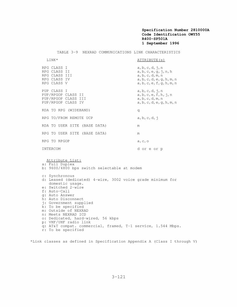
Specification Number 2810000ACode Identification OWY55 R400-SP501A 1 September 1996
3-121
TABLE 3-9 NEXRAD COMMUNICATIONS LINK CHARACTERISTICS LINK* ATTRIBUTE(s) RPG CLASS I a,b,c,d,j,n RPG CLASS II a,b,c,e,g,j,n,h RPG CLASS III a,b,c,d,m,n RPG CLASS IV a,b,c,d,e,g,h,m,n RPG CLASS V a,b,c,e,f,g,h,m,n PUP CLASS I a,b,c,d,j,n PUP/RPGOP CLASS II a,b,c,e,f,h,j,n PUP/RPGOP CLASS III a,b,c,d,m,n PUP/RPGOP CLASS IV a,b,c,d,e,g,h,m,n RDA TO RPG (WIDEBAND) q RPG TO/FROM REMOTE UCP a,b,c,d,j
RDA TO USER SITE (BASE DATA) m RPG TO USER SITE (BASE DATA) m RPG TO RPGOP a,c,o INTERCOM d or e or p
Attribute List: a: Full Duplex b: 9600/4800 bps switch selectable at modem c: Synchronous d: Leased (dedicated) 4-wire, 3002 voice grade minimum for domestic usage. e: Switched 2-wire f: Auto-Call g: Auto Answer h: Auto Disconnect j: Government supplied k: To be specified
m: Outside of NEXRAD n: Meets NEXRAD ICD o: Dedicated, hard-wired, 56 kbps p: VHF/UHF radio link q: AT&T compat. commercial, framed, T-1 service, 1.544 Mbps. r: To be specified
*Link classes as defined in Specification Appendix A (Class I through V)
Specification Number 2810000ACode Identification OWY55 R400-SP501A 1 September 1996
3-122
When the RPG/PUP is located at the Principal User Site, the Governmentwill provide an appropriate (minimum 100 pair capacity) narrowbandcommunications demarcation frame (standard telephone wire terminationrack) and the cable connecting the frame to a telephone company (TELCO)exchange. An appropriate multi-conductor cable with sufficient capacityto connect the maximum number of narrowband ports (as defined inparagraphs 3.7.2.5.13 and 3.7.3.6.6) shall (3) be provided and installedfrom the RPG/PUP modem locations to the narrowband communicationsdemarcation frame. Both ends of this cable shall (4) be appropriatelymarked to allow future connections as additional modems are installed.
When the RPG is located at the radar site, the contractor shall providea narrowband communications demarcation frame with the capacity toterminate 100 pairs of telephone cable shall (5) be provided. Anappropriate multi-conductor cable with sufficient capacity to connectthe maximum number of narrowband ports as defined in paragraph3.7.2.5.13 shall (6) be provided and installed from the RPG modemlocations to the narrowband communications demarcation frame. Both endsof this cable shall (7) be appropriately marked to allow futureconnection as more modems are installed. Provisions for intrusivenarrowband line testing shall (10) be included. Intrusion shall (11)allow on-line monitoring as well as the ability to break the line(s) forlook-back and look-forward testing. The point of intrusive testingshall (12) be at communications/equipment racks or cabinets and shall(13) provide for easy connection of test equipment via a patch panel orother similar equipment. The Government will be responsible for cross-connects at the narrowband communications frame and activation ofservice. Commercial telephone service provided by the Government willsupport 3002 type voice grade private lines.
In the following sections, the required general modem characteristicsfor all narrowband communications links are first described, followed byspecific communications link characteristics.
3.7.4.1 General Modem Characteristics
All modems shall (1) be mounted in a contractor supplied cabinet; themounting technique shall (2) provide for rapid replacement of eachmodem.
In the United States and controlled territories, the contractor shall(3) use the CCITT V.29 four wire modem or a CCITT V.32 four wire modemfor all dedicated links. In addition, the CCITT V.32 two-wire modemshall (3a) be used for all dial-up links. Each RPG and all of itsassociated PUPs shall (3b) have dedicated modems that are compatible toeliminate any interoperability problems between RPGs and PUPs. Allmodems shall (4) have a test capability to include local analog andremote digital loop-backs. Indicators, as a minimum, shall (5) beprovided for power-on, test mode, carrier-on, clear to send, and requestto send.
All dial-up lines shall (6) have an automatic calling unit (ACU)capability. All dial-up modems shall (7) respond to a call-disconnectinitiated by either an operator-entered command or a predefined set ofconditions at either end of the link.Modems and ACUs being installed at overseas locations shall (8) meet the

Specification Number 2810000ACode Identification OWY55 R400-SP501A 1 September 1996
3-123
requirements for data transmission specified in Appendix A. V.29 andV.32 modems shall (9) be used wherever permitted by the affectedoverseas nation. Homologation shall (10), however, be a contractorresponsibility in Great Britain, the Federal Republic of Germany, Spain,the Republic of orea, the Republic of the Philippines, Japan, Italy,Portugal, the Republic of Panama, and the Netherlands.
3.7.4.2 Communications Links Characteristics
Table 3-9 delineates the characteristics of each type of NEXRAD datacommunications link. Allowable options within the existing classes, asdefined in Appendix A, shall (1) be controlled through adaptation databy the RPG and PUP control consoles. These options shall (2) beselectable for each individual port with that assigned class.
If wideband communication is required the design shall (3) allowinterface cables to be readily replaced by microwave radios and antennasor other wideband communications equipment. The inherent availabilityof the microwave and fiber optic wideband communications system,including both communications hardware and the communications path,shall (4) be greater than or equal to 0.9990.
3.7.4.3 Communications Security
For all dial-in communication ports, provisions shall (1) be made toidentify users and deter access to the RPG and PUP beyond allowedrequests. Any invalid entry shall (2) be responded to with an errormessage. Three such invalid entries by the same user shall (3) resultin immediate disconnection from that port. Site adaptable passwords foreach port and each user shall (4) be required to access any data fromthat port.
3.7.4.3.1 Communications Disconnect
For each dial-in port, the calling site shall (1) be automaticallydisconnected after a time limit has been reached. When the time limithas been reached, the product currently being transmitted shall (2) becompleted before disconnecting the caller. This time limit shall (3) beadjustable and shall (3) be independently controllable for each dial-inport from the appropriate RPG (UCP) or PUP. A capability shall (4) beprovided to allow designated users to override the disconnect feature ofany port.
3.7.4.4 Microwave-Line-of-Sight System
A microwave line-of-sight (MLOS) system shall (1) be one option toprovide wideband communications. The option for the microwave antennasat the radar site to be mounted either on the NEXRAD radar tower or on aseparate tower which is not less than 200 ft from the NEXRAD radar towershall (2) be provided. The MLOS system shall (3) comply with therequirements defined in 3.2.6. The MLOS system shall (4) employ a FaultAlarm System (FAS) which shall (5) monitor all MLOS major and minoralarms. When active repeaters are used, the state and condition of thepower source and MLOS repeater alarms shall (6) also be monitored. TheFAS will have both audible and visual alarms. The FAS alarms shall (7)be reported at the UCP location. At selected sites the contractor shall
Specification Number 2810000ACode Identification OWY55 R400-SP501A 1 September 1996
3-124
(8) provide obstruction lighting on the MLOS towers in accordance withFAA specifications AC 70/7460-1F.
3.7.4.4.1 Microwave Repeaters
Microwave radio repeater sites shall (1) operate from commercial primarypower. A 24 hour capacity back-up battery system shall (2) be provided. The contractor shall (3) also provide back-up generator power. Thisshall (4) have a seven day running capacity and shall (5) beautomatically initiated after a loss of commercial power of 1 hour orgreater. After commercial power has been restored for at least 1 hour,the site shall (6) be automatically switched back to commercial power. Each change in power source shall (7) result in appropriate reporting atthe FAS.
3.7.4.4.2 MLOS Facilities
MLOS antennas, reflectors, and towers shall (1) comply with EIAStandards 195-C and 222-E. Wind loading design for all towers shall(1a) be EIA Zone B at a minimum. In cases where a separate MLOS toweris employed at the radar, repeater, or principal user site, the optionfor a radio shelter shall (2) be provided to house the MLOS equipment. The radio shelter shall (3) support operation of the MLOS equipment overthe range of the outdoor environmental conditions defined underparagraph 3.2.6.1.

Specification Number 2810000ACode Identification OWY55 R400-SP501A 1 September 1996
3-125
FACILITIES SEGMENT
Specification Number 2810000ACode Identification OWY55 R400-SP501A 1 September 1996
3-126
3.7.5 Facilities Functional Area
The Facilities functional area includes construction or modification ofbuildings and towers, provision and installation of Real Property Installed Equipment (RPIE) such as power generation and air conditioningequipment, and construction of access roads which are needed in support of the RDA, RPG, PUP, Communications, and Support functional areas. Allmechanical and electrical alignment of the antennas for widebandcommunications links, including at repeater installations shall (00) beprovided.
1. Contractor Responsibilities
At each radar site and MLOS site, All required NEXRADequipment, structures, and NEXRAD support equipmentincluding but not limited to: access roads (in accordancewith Appendix M), utilities and utility extensions, footingsand foundations, ancillary equipment shelter(s) andassociated footings and foundations, towers, environmentalcontrol, backup power, fuel storage and associated piping,grounding, security fencing, and wideband communicationslink to user site including any wideband repeaterinstallations shall (1) be provided. At the Government'soption, towers constructed at selected sites shall (2) be ofstructural steel. For MLOS, repeater, and passive reflectortowers, an option for either a self-supporting tower or aguyed tower shall (3) be provided. Provisions for acommercial T-1 (1.54 Mb/s) service to replace Microwave maybe required at certain sites. Provisions to house the RPGequipment when collocated at the radar site shall (4) alsobe provided, including the fully expanded RPG, the redundantconfiguration of 3.2.1.5.1, 3.2.1.5.2, and the combinationof both.
An automatic fire suppression capability for the NEXRADindoor environment equipment located at the radar site(excluding radome interior) shall (5) be provided.
At each principal user site all required NEXRAD equipmentand NEXRAD support equipment shall (6) be provided,installed and tested.
2. Government Responsibilities
For each radar site and MLOS site the Government willprovide a survey of the selected site which includes aconceptual site plan and basic information concerningutilities, rough topography, soil type, climate, expectedclutter, recommended frequency and tower height, andrecommended locations/routings of access roads and widebandcommunication installations (as applicable). Theacquisition of land, as required, will be a Governmentresponsibility.
For each principal user site the Government will provide asurvey of the selected site which includes a location plan,
Specification Number 2810000ACode Identification OWY55 R400-SP501A 1 September 1996
3-127
a floor plan, and information concerning utilities andlocations of wideband communication installations (asapplicable). The Government is responsible for equipmentlayout and design of principal user site buildingmodifications in accordance with Section 5"Responsibilities" of "PUP Site Survey Instructions andInformation Package".
Equipment supplied shall (7) satisfy the requirements with respect tospace, electrical, environment, and architecture as specified inSections 3.7.5.1 through Section 3.7.5.4, respectively.
3.7.5.1 Space
Equipment to be located in an operator work area at a principal usersite comprising all equipment required to perform any operator function including all PUP functional area equipment, and the unit control position, shall (1) not require a horizontal area greater than 12 square meters.
3.7.5.2 Electrical
The equipment installed in the NEXRAD facilities shall satisfyelectrical requirements related to:
1. Power Characteristics2. Lighting3. Cables4. Electromagnetic Interference Shielding5. Internal and External Cableways6. Grounding
3.7.5.2.1 Power Characteristics
The power characteristics for Government supplied facilities willsatisfy the following:
Steady State Voltage 120/208 VAC + 10%(3 Phase, 4 wire)
Steady State Frequency 60 Hz + 5%
Each NEXRAD Unit shall (1) be designed to be compliant with "NWSTransient Susceptibility Standard," May 1978, with respect to lightning,transient suppression, and motor starting disturbances caused by the airconditioning system when both the air conditioning system and otherNEXRAD equipment are operating in parallel and receiving power from astandby engine/generator.
To accommodate overseas installations, the capability to convertalternate primary power sources to the standard NEXRAD primary powerdefined above shall (2) be provided. Optional provisions shall (3) bemade to accommodate the following primary voltage and frequencyconfigurations:
Specification Number 2810000ACode Identification OWY55 R400-SP501A 1 September 1996
3-128
single three freqphase phase involts AC volts AC Hertz
1. 120 208 60 (typical U.S. NEXRAD) 2. 127 220 50 3. 220 380 50 4. 230 400 50 5. 240 415 50 6. 277 480 50 7. 100/200 - 50 8. 100/200 - 60 9. 110/220 - 60
A single frequency converter shall (4) be provided to support acollocated RDA/RPG. A separate converter shall (5) be provided tosupport the PUP. When connected to the 50 Hz power through the frequencyconverter, all other aspects of the NEXRAD system shall (6) remainunchanged.
Each NEXRAD Unit shall (7) withstand a power outage without any damage. It shall (8) be capable of automatic restarting and rapid recovery afterpower is restored.
3.7.5.2.2 Lighting
Radome and MLOS obstruction lighting shall (1) be provided as perspecification AC 70/7460-1F. Otherwise, NEXRAD facilities shall (2) notrequire any special lighting effects other than incandescent lightingwith dimmer control.
3.7.5.2.3 Cables
Cables used in an outdoor environment shall (1) be designed for directearth burial and shall (2) be armored to be gopher resistant. The cableshielding, grounding, and routing shall (3) be in accordance withparagraph 5.1.1.2.5 of MIL-STD-188-124B, using the guidelines ofMIL-HDBK-419. The limits on electromagnetic emissions andsusceptibility shall (4) be as stated in Section 3.2.6.11 of thisdocument.
3.7.5.2.4 Electromagnetic Interference Shielding
The NEXRAD radar shall (1) include sufficient electromagneticinterference shielding and filtering to meet the requirements stated inSection 3.2.6.11. The requirements and practices to be followedregarding shielding effectiveness, screening, seams/joints/apertures,gaskets, and conductive surface coating shall (2) be as given inparagraph 5.3.2 of MIL- STD-188-124B, using the guidelines ofMIL-HDBK-419.
The guidelines for attenuation requirements, selection of suppressioncomponents, and mechanical considerations as described by the ElectronicIndustries Association (Filtering Electronic Equipment, Bulletin No. 9)shall (3) be used.
Specification Number 2810000ACode Identification OWY55 R400-SP501A 1 September 1996
3-129
3.7.5.2.5 Internal and External Cableways
Cableways shall (1) be in accordance with National Electrical Code (NEC)requirements and shall (2) meet electromagnetic interferencerequirements specified in Section 3.2.6.11.
3.7.5.2.6 Grounding
The NEXRAD equipment shall (1) operate with a facility grounding systemwhose resistance complies with the National Electrical Code. Thegrounding connections and grounding methods shall (2) be as required inparagraph 5.1.1.3 of MIL-STD-188-124B, using the guidelines of MIL-HDBK-419. The resistance of the NEXRAD equipment to earth shall (3) be 10ohms or less.
3.7.5.3 Environmental
The equipment installed in NEXRAD facilities shall (1) satisfyenvironmental requirements related to:
1. Personnel2. Equipment3. Electromagnetic Environment
3.7.5.3.1 Personnel
Operating and maintenance personnel shall (1) be provided with acomfortable working environment that meets the safety requirements ofSection 3.3.6.
3.7.5.3.2 Equipment
Equipment shall (1) be compatible with the environment in which it willoperate and shall (2) not cause any deleterious effects on the naturalenvironment.
To provide visual compatibility with the environment, provisions shall(3) be made for optional alternate colors of: the radome, the tower,and any other major outdoor facility item such as a separate shelter,backup power generator, etc. The choice of alternate colors to beprovided shall (4) be in accordance with color numbers 30219, 34127, and34258 of FED-STD-595A. For FAA safety reasons, provisions shall (5) bemade for optional alternate colors of the tower structure (radome notincluded) in accordance with paragraphs 8, 9, and 10.b of AC 70/7460-IF. Colors of the final materials shall (6) be subject to Governmentapproval.
3.7.5.3.3 Electromagnetic Environment
The 2.7-2.9 GHz band, nationally, is a Government-exclusive frequencyband intended for the primary use of the Aeronautical RadionavigationService (air traffic control radars) and the Meteorological Aids Service(weather radars). The NEXRAD System shall (1) be capable of operatingin the Communication Electronics equipment environments within CONUS aswell as at DOD overseas bases. This will require preplanning and EMCanalysis to minimize the impact of interfering signals. To ensure that

Specification Number 2810000ACode Identification OWY55 R400-SP501A 1 September 1996
3-130
the NEXRAD System will not be susceptible to electromagneticinterference within the allocated frequency band, the following stepsshall (2) be taken:
1. The NEXRAD antennas shall (3) be capable of being located atthe sites designated by the Government.
2. The NEXRAD design shall (4) take into account the presenceof a composite interference signal profile. A compositeinterference signal profile (composite of contributing PRFs,scan rates, pulse widths, frequencies, etc.) can be based onequipment in the high equipment density areas within CONUS. Appendix F lists the baseline electromagnetic environmentfrom which an interference signal profile can be developed.
3. The NEXRAD design shall (5) provide the flexibility toincorporate the recommendations of EMC analysis. Therecommendations may include one or more of the followingitems:
a) [Shall (5a)] Inserting filters in the receiverequipment,
b) [Shall (5b)] Providing adjustable transmitter andreceiver frequencies in the allocated band,
c) [Shall (5c)] Augmenting the signal processing softwarecapability,
d) [Shall (5d)] Incorporating special rejection circuitsfor interference, and
e) [Shall (5e)] Providing adjustable antenna coveragevolume.
3.7.5.4 Architecture
The equipment installed in NEXRAD facilities shall (1) satisfyarchitectural requirements related to:
1. Clearances2. Access3. Human Factors4. Telephone and Intercom
3.7.5.4.1 Clearances
Consoles and cabinets shall (1) be of a modular design with no unitexceeding 0.8 m x 1.2 m in plan; the vertical dimension shall (2) notexceed 2 m.
3.7.5.4.2 Access
Access to all enclosures for cabling and ventilation shall (1) bedesigned to allow installation on both standard and raised floorfacilities. A cable access capability shall (2) be provided through the

Specification Number 2810000ACode Identification OWY55 R400-SP501A 1 September 1996
3-131
rear of the cabinet near the base, and also through the bottom surfaceof the cabinet. Ventilation openings shall (3) be limited to the front,rear, and top surfaces of the cabinet.
3.7.5.4.3 Human Factors
Consoles and other equipment shall (1) conform to the principles ofHuman Factors as stated in Section 3.3.7.
3.7.5.4.4 Telephone/Intercom
The equipment shall (1) include provisions for telephone/intercomcapability for the operational and system consoles. At a minimum, theintercom capability shall (2) provide for simultaneous voicecommunication among all of the following locations/positions: the radomeinterior, the RDA maintenance position, and the Unit Control Position. The intercom system shall (3) operate independent of primary power.
All equipment, cabling, and connections to accomplish this functionshall (4) be provided. When the operational site (UCP location) is notcollocated with the radar site, options for UHF/VHF radios, dedicatedleased line, or dial-up service shall (5) be provided in lieu of cablingfor the remote connection.

Specification Number 2810000ACode Identification OWY55 R400-SP501A 1 September 1996
3-132
SUPPORT SEGMENT
Specification Number 2810000ACode Identification OWY55 R400-SP501A 1 September 1996
3-133
3.7.6 Support Function Area
The Support functional area includes maintenance and logistics,training, development and test, and support software.
3.7.6.1 Maintenance and Logistics Support
For maintenance and logistics support, depot operational equipment,initial spares, maintenance support equipment, and off-line diagnosticsshall (1) be provided, as defined below.
3.7.6.1.1 Depot Operational Equipment
A set of NEXRAD operational equipment shall (1) be provided for themaintenance depot. This equipment shall (2) comprise that required toprovide a configuration equal to the largest NEXRAD Unit configurationprovided at any operational site.
3.7.6.1.2 Initial-Spares
Initial spares shall (1) be provided to support the maintainability(3.2.4), availability (3.2.5), and maintenance (3.5.1) requirements ofthis document. Initial spares provisioning shall (2) satisfy bothsupport and operational facility requirements and be consistent withminimizing life cycle costs.
3.7.6.1.3 Maintenance Support Equipment
Maintenance support equipment shall (1) and (2) be identified viaSupport Equipment Recommendation Data (SERDs) for the training andoperational test facilities, and the operational facilities.
3.7.6.1.4 Off-Line Diagnostics
An off-line diagnostic capability shall (1) be provided at eachmaintenance and logistics support facility and within each NEXRAD Unit. This capability shall (2) permit isolation of faults to the LRU or groupof three LRUs. Fault isolation shall (3) be manually initiated, withall manual actions requested via prompts.
In addition to isolating equipment failures, the off-line diagnosticcapability shall (5) verify the correct operation of the equipment afterthe failure has been corrected.
3.7.6.2 Training Support
Support shall be provided for both maintenance and operational training,including OJT.
3.7.6.2.1 Maintenance Training Support
For maintenance training, both operational equipment and maintenancesupport equipment shall (1) be provided. The maintenance supportequipment shall (2) contain those portions of the maintenance supportequipment described in Section 3.7.6.1.3 for the maintenance depot which
Specification Number 2810000ACode Identification OWY55 R400-SP501A 1 September 1996
3-134
are required for maintenance training.
3.7.6.2.2 Operational Training Support
Operational equipment, training support equipment, and software shall(1) be provided to support operational training at each of the NEXRADtraining facilities (see Section 3.1.1.6.3).
3.7.6.2.2.1 Operational Equipment
A set of operational data processing and display and data entryequipment with appropriate software shall (1) be provided to each NEXRADoperational training facility. Each set shall (2) include multipletraining consoles and shall (2) support training for all operationalpersonnel.
3.7.6.2.2.2 Training Support Equipment
All equipment required to support training as called out in theGovernment approved Training Plan shall (1) be provided.
3.7.6.2.2.3 Operational Training Software
Software shall (1) be provided as required to support operationaltraining at each NEXRAD operational training facility. Software foron-the-job training at NEXRAD operational facilities shall (2) beprovided as specified in Section 3.7.6.4.7.
3.7.6.3 Development and Test Support
A development and test facility, referred to as the Operational SupportFacility (OSF), will provide the Government a facility for developmentand test of hardware and software changes (see Section 3.1.1.6.4). Thisfacility shall (1) contain the first article NEXRAD Unit, upgraded toproduction configuration and quality during the Limited ProductionPhase. The development and test facility, along with support software,as defined in Section 3.7.6.4, and all required support hardware, shall(2) provide the Government with the capability to perform NEXRADoperational software maintenance and enhancements, perform systemperformance evaluations for any hardware or software changes prior tofield implementation, and evaluate new meteorological analytictechniques prior to field implementation.
3.7.6.4 Support Software
The following support software capabilities shall (1) be provided:
1. Adaptation Data Generation2. Data Maintenance3. Software Development and Production4. System Generation5. Software Maintenance6. Computer Performance Monitoring7. OJT Training Support8. Test Data Generation9. Test Software

Specification Number 2810000ACode Identification OWY55 R400-SP501A 1 September 1996
3-135
10. Program Support Library
Specification Number 2810000ACode Identification OWY55 R400-SP501A 1 September 1996
23 Defined in Appendix B
24Defined in Appendix B.
3-136
3.7.6.4.1 Adaptation Data Generation
Adaptation data23 is that data which is used in calculations that relateto a specific RDA, RPG, or PUP site. This data includes the latitude,longitude, and elevation of a site and the geographic information usedto generate maps applicable to that site.
Adaptation data generation software shall include:
1. The capability to generate adaptation data for the entiresystem [Shall (1)] or any subset of the entire system [Shall(2)], and store the generated data on a mass storage device[Shall (3)],
2. The capability to accept input from an operator's console oran input file [Shall (4)] which specifies which adaptationdata to generate and how to generate it,
3. The capability to add, modify, or delete data from theadaptation data base [Shall (5)], and
4. The capability to translate map coordinates given inlatitude and longitude to display coordinates [Shall (6)] .
3.7.6.4.2 Data Maintenance
The capability shall (1) be provided to perform maintenance activities(e.g., corrections, updates, additions, and deletions) on data usedwithin the RPG and PUP functional areas. This capability will be usedprimarily to maintain the adaptation, geographic data bases and specialcharacters and symbols associated with the RPG and PUP functional areas,although the uses of the data maintenance capabilities should not belimited to these three functions.
3.7.6.4.2.1 Adaptation Data Maintenance
The adaptation data24 maintenance software shall include:
1. [Shall (1)] The capability to identify a particular set ofadaptation data and copy it from a mass storage device,
2. [Shall (2)] The capability to make local changes to theadaptation data base for a particular facility,
3. [Shall (3)] The capability to merge a local adaptation database with a more general adaptation data base and produce asingle composite data base, and
4. [Shall (4)] The capability to record all changes andadditions made to the adaptation data base.

Specification Number 2810000ACode Identification OWY55 R400-SP501A 1 September 1996
3-137
3.7.6.4.2.2 Geographic Data Maintenance
The geographic data maintenance software shall include:
1. [Shall (1)] The capability to identify a particular set ofgeographic data and copy it from a mass storage device,
2. [Shall (2)] The capability to make local changes andadditions to a geographic data base,
3. [Shall (3)] The capability to combine two or more maps intoa single map and retain this map for later use, and
4. [Shall (4)] The capability to record all changes made to thegeographic data base.
3.7.6.4.2.3 Special Symbol Maintenance
The special symbol maintenance shall include:
1. [Shall (1)] The capability to re-define the special symbolset by re- defining the pixel elements corresponding to eachof the symbols, and
2. [Shall (2)] The special symbols shall consist of at least a7 x 9 pixel matrix.
3.7.6.4.3 Software Development and Production
All software required to develop and maintain the NEXRAD System shall(1) be provided to a central Government facility. For all software, theexecutable form of the software, the source code, and all CDRLdocumentation and training aids shall (2) be provided. At least thefollowing software shall (3) be provided:
1. Compiler(s). This software is used to translate programswritten in a high order language. The compiler shall (4) produce relocatable machine code that is compatible with thelinking and loading requirements of the hardware in use.
2. Assembler. This software is used to translate programswritten in mnemonic assembly language into absolute andrelocatable machine code. The assembler shall (5) have thecapability to handle macro routines. The output of theassembler shall (6) be compatible with the linking andloading conventions of the hardware.
3. Linker. This software produces relocatable machine-executable code from the outputs of the assembler and thecompiler. The linker shall (7) be able to combine modulesproduced by both the assembler and the compiler into asingle executable entity. The linker shall (8) also supportthe use of overlays and user-produced, run-time librariesand shall (9) have the capability to produce detailedlistings describing the executable code.
Specification Number 2810000ACode Identification OWY55 R400-SP501A 1 September 1996
3-138
4. Run-Time Libraries. This set of relocatable routines resolves external references generated by the linker. At aminimum, run-time libraries shall (10) be provided toresolve the external references associated with the outputsof the compiler and the assembler.
5. Loader. This software takes the output of the linker, loadsit into memory, and initiates its execution (in conjunctionwith the operating system). The loader shall (11) have thecapability to resolve relocatable addresses and to handleoverlays.
6. Text Editor. This software enables a user to create andmanipulate files that contain source language statements ordata. The text editor shall (12) be usable in aninteractive mode.
7. File Maintenance Utilities. This software provides generalfile handling capabilities for both program and data files. The file maintenance utilities shall (13) have thecapability of creating and maintaining run-time libraries.
8. Sort/Merge Utility. This software provides for sorting andmerging data files. The sort/merge utility shall (14) becallable from a routine written in a high order language orin assembly language. It shall (15) also be usable as astand-alone program.
9. Debugger. This software enables a user to executesymbolically a program written in either assembly languageor a high order language from an interactive terminal. Thedebugger shall (16) provide the following features:
a) Single step execution of the program being debugged,
b) Setting of breakpoints both symbolically and by linenumber,
c) The ability to examine the values of variables, thecontents of memory, and the contents of registers,
d) The ability to change variable values and register ormemory contents during the course of a debuggingsession,
e) The ability to selectively debug subroutines containedas part of a larger main program,
f) The ability to turn the debugging feature on and offwithout changing the source code of the routines beingdebugged, and
g) The ability to debug real-time programs at theinterrupt level.
Specification Number 2810000ACode Identification OWY55 R400-SP501A 1 September 1996
3-139
3.7.6.4.4 System Generation
System generation is the process of building a software system from itscomponent parts. System generation software shall (1) perform theselection of the required components for a system, the application ofthe necessary updates, and the construction of the executable version ofthe software. To aid in this process, special utility programs are usedto simplify and speed up the system generation. The following systemgeneration programs shall (2) be provided to a central Governmentfacility:
1. Adaptation Data Base Utility. This program is used tomanipulate the site-specific adaptation data associated witheach user site. This program shall (3) take the adaptationdata generation for each site and put it in the formatrequired by the operational software that processes thisdata. This program shall (4) have the capability to runinteractively, using prompts to solicit all operator input,or to run in batch mode.
2. System Generation/Integration Utility. This program is usedto create the executable software, including all applicationand system software required as part of the RDA, RPG, andPUP functional areas. This program shall (5) use thesoftware development and production software packages (e.g.,assembler, compiler, and linker) to create executablesoftware either entirely from source code or from acombination of previously compiled or assembled modules andnewly created or modified source modules. This programshall (6) have the capability of being run as a backgroundtask in parallel with other development work. It shall (7)be capable of being run in either a batch or an interactivemode. All indirect command files or skeleton runstreamsrequired to run this program shall (8) be provided.
3. System Delivery Utility. This program is used to format acopy of the software system required for each computer sitein the network whenever a new software system is generated.The program shall (9) produce as output the properlyformatted software corresponding to the configuration ateach site. This output shall (10) be placed on the selectedstorage medium. The input to the system delivery utilitywill be the output of the system generation utility and theappropriate output of the adaptation data base utility. This program shall (11) operate in either an interactivemode, with prompts for all required operator input, or in abatch mode.
4. Bootstrap Loader. This program is used for the initialloading of the system software. The bootstrap loader shall(12) be permanently resident in nonvolatile memory and shall(13) be initiated by the operator, once the system ispowered up, via a single switch. Once the operating systemis loaded, the bootstrap loader shall (14) relinquishcontrol to the operating system. The bootstrap loader shall(15) be initiated by the operator during a startup. In the
Specification Number 2810000ACode Identification OWY55 R400-SP501A 1 September 1996
3-140
event of a restart after a short-term power failure or otherrecoverable error, the bootstrap loader shall (16) becapable of being initiated automatically.
3.7.6.4.5 Software Maintenance
The capability to perform maintenance on the operational software shall(1) be provided. This shall include:
1. [Shall (2)] The capability to make a change in theexecutable form of a program without recompiling orrelinking (The change is made by altering, adding, ordeleting machine language instructions, or data inmachine-readable form, and is commonly called "patching."),
2. [Shall (3)] The capability to display the contents ofmemory,
3. [Shall (4)] The capability to set breakpoints under operatorcontrol, and
4. [Shall (5)] The capability to display the current systemconfiguration (hardware and/or software) withoutinterrupting system operation.
3.7.6.4.6 Computer Performance Monitoring
A capability shall (1) be provided to record information concerning theutilization of the various equipment items and to format thisinformation into a form suitable for output as a report. At a minimum,this capability shall (2) provide the following information (average andpeak):
1. [Shall (2a)] Memory Utilization
2. [Shall (2b)] CPU Utilization
3. [Shall (2c)] Mass Storage Utilization
4. [Shall (2d)] I/O Channel Utilization
5. [Shall (2e)] Communications Line Utilization
6. [Shall (2f)] Response Time
The above information shall (3) be used to generate a periodic report. The report shall (4) be capable of being printed on a hardcopy device.
3.7.6.4.7 OJT Training Support
Training software shall (1) be provided to support OJT within a PUP. APUP shall (2) be able to perform OJT independently of whether the RPG orany other PUP in the NEXRAD Unit is operational. (Training softwarerequired to support the NEXRAD training facility is defined in Section3.7.6.2.)
Specification Number 2810000ACode Identification OWY55 R400-SP501A 1 September 1996
3-141
During OJT, the training software shall (3) enable a PUP operator toaccess the entire range of functions performed by the operationalsoftware using either live or recorded data. During OJT, the operatorshall (4) be able to select portions of the operational data base fortraining purposes, and also be able to build and maintain a data base tobe used exclusively for training.
Training software shall (5) permit PUP OJT while simultaneouslymonitoring the associated RPG interface for alert messages; in thiscase, products, with the exception of alert messages, need not beprocessed by the PUP (although they shall (6) be retained in the RPGdata base). When an alert message is received by a PUP performing OJT,it shall (7) be presented to the PUP operator in accordance with Section3.7.3.3.7.
3.7.6.4.8 Test Data Generation
Test data generation software shall (1) be provided for use indeveloping, testing, and maintaining the NEXRAD operational software andin training NEXRAD operators, users, and maintenance personnel. Thedata generated shall (2) be stored in a transportable, machine readableform.
The test data generation software shall (3) provide the capability togenerate simulated radar data, including noise returns and echoes, andto process [Shall (4)] inputs which specify the characteristics of thetest data to be generated.
3.7.6.4.9 Test Software
Test software shall (1) be provided to verify the performance of theoperational software.
The test software shall:
1. [Shall (2)] Be operable in an interactive mode withprompting for all required inputs,
2. [Shall (3)] Be operable in an automatic mode requiringminimum operator action,
3. [Shall (4)] Generate formatted output products that show theresponses associated with each input and the cumulativeresults for each test,
4. [Shall (5)] Include data samples that are both within andoutside the range specified for the function under test, and
5. [Shall (6)] Be subject to the same quality controlprocedures as the operational software.
3.7.6.4.10 Program Support Library (PSL)
An automated PSL shall (1) be built for use throughout the softwaredevelopment project in accordance with requirements stated herein(unless an existing or an alternative plan is specifically agreed upon
Specification Number 2810000ACode Identification OWY55 R400-SP501A 1 September 1996
3-142
as an acceptable functional equivalent by the Government). The PSL andits related documentation shall (2) be delivered to the Government withunlimited data rights.
The PSL shall (3) consist of computer programs and a data repositorywhich shall (4) be established and maintained under control of alibrarian. Facilities and procedures for the generation, storage andmaintenance of all software shall (5) be implemented. Thisimplementation shall (6) provide for full privacy/access constraints,documentation support, and management data collection and reporting. The procedures established shall (7) provide the following:
1. The identification and delegation of responsibilities forclerical and record keeping functions associated with theprogramming process and the maintenance of the library,
2. The delegation of responsibilities for all machineoperations with regard to such items as projectinitiation/termination, program test philosophy, and outputmedia/frequency,
3. The procedures for recording, cataloging, and filing of allcode generated on the project, both intermediate and final,and for the retention of superseded code for statedretention periods,
4. A method for controlling and building multiple versions ofthe code contained in the library and a method for providingvisibility into this process by configuration managementpersonnel, and
5. A method for collecting and disseminating basic managementdata on the use of the library facilities and status of the programming activities.
Specification Number 2810000ACode Identification OWY55 R400-SP501A 1 September 1996
4-1
4. QUALITY ASSURANCE
This Quality Assurance section establishes the Test and Evaluation (T&E)requirements for the NEXRAD System.
4.1. Scope of Test and Evaluation
Quality Assurance T&E includes Development Test and Evaluation (DT&E),Production Acceptance Test and Evaluation (PAT&E), and Operational Testand Evaluation (OT&E).
DT&E is that T&E required during the acquisition of the NEXRAD System tosatisfy the Government that the baseline requirements have been met. DT&E covers all functional areas within the system, all configurationitems of hardware and software (including firmware), all internal andexternal interfaces, and all automatic test equipment hardware andsoftware.
PAT&E is that T&E conducted to demonstrate that items procured fulfillthe requirements and specifications of the procuring contract oragreements.
OT&E is that T&E which evaluates the operational effectiveness andsuitability of the NEXRAD system in its operational environment. TheGovernment is responsible for the planning and conduct of OT&E. OT&Ewill be conducted in the Validation, Limited Production, and ProductionPhases.
4.1.1 Test Phases
Test and evaluation activities are required during the Validation,Limited Production and Production Phases. The Validation Phase test andevaluation is described in detail in Section 4.2. The LimitedProduction Phase test and evaluation is described in Section 4.3, andthe Production Phase test and evaluation is described in Section 4.4.
4.1.2 General Test Requirements
The following general test requirements are common to all parts of theNEXRAD T&E. hese requirements shall be satisfied in the preparation ofthe detailed test documentation defined herein and in the conduct of therequired tests.
1. The Government will have the right to witness all tests. However, the Government may choose to accept written proofof satisfactory completion of certain factory tests in lieuof being present to witness the test.
2. The Government may require a test of any baselinerequirement. Test documentation shall be updated to reflectchanges in test requirements that result from changes to thebaseline requirements, unless otherwise stated in theapplicable contract change.
3. All test documentation defined herein, all test inputs, alltest software, all test instrumentation (properly
Specification Number 2810000ACode Identification OWY55 R400-SP501A 1 September 1996
4-2
calibrated), and all test personnel resources needed fortesting, shall be provided unless specifically statedotherwise in this document.
4. Copies of all documents referenced in test documentationshall be provided to the Government. These copies shall beprovided at the time of the initial submission of therelated test documentation.
5. Successful completion of software and hardware tests will beused to mark particular milestones and to gauge contractorprogress. Final acceptance of items required by thecontract will occur as a result of successful completion ofapplicable system level tests of NEXRAD Units.
6. Pretest inspections shall be required prior to each test. The test inspections shall ensure that the testconfiguration is in accordance with approved testprocedures, that the equipment and software are at thecorrect revision level, and that prior deficiencies ordiscrepancies have been corrected. The test inspectionsshall also ensure that all test documentation and testequipment are available.
7. The Government shall be notified at least 30 working days inadvance of planned tests, with reconfirmation provided tothe Government 10 working days in advance of the scheduledtests.
8. The configuration for each test shall be identified in thetest plans. Selection of the test configuration shall besupported by reliability/availability data and proof thatall equipment, software, and interfaces will be exercised.
9. Completion of tests defined herein shall not in any way voidthe warranty and latent defect clauses nor waivedrequirements for delivery of a compliant system.
10. The Government may, at its discretion, require retest ofpreviously completed tests where it is judged by theGovernment that correction of a deficiency may affect theresults of prior testing. However, for Commercial-Off-The-Shelf equipment (unmodified for the NEXRAD system ), retestshall not be required for alternate (both earlier and later)revisions or part number changes that do not affect form,fit, or function to the same vendor commercial equipmentwhen such changes were not implemented to correct adeficiency identified in prior NEXRAD testing. In such acase, verification shall be made that the other version ofthe equipment meets all applicable NEXRAD requirements.
11. The Government can stop any test if progress is not adequateand major retesting will be required.
4.1.3 Documentation Requirements

Specification Number 2810000ACode Identification OWY55 R400-SP501A 1 September 1996
4-3
Detailed test documentation shall be submitted. Each document shall besubmitted as specified by the Government.
4.1.3.1 Test Plans
Test plans for each of the program phases shall be submitted. The testplans shall describe in specific terms how the contractor will satisfythe requirements of the specifications. The approved test plans shallserve as the basis for preparation of the test procedures.
4.1.3.2 Test Procedures
Detailed test procedures shall be submitted. The procedures shall bebased on the specified test requirements. Separate test proceduresshall be submitted for each major test to be performed as defined in theapproved test plans.
4.1.3.3 Test Data Sheets
Test data sheets consistent with the test procedures shall be provided. The test data sheets will be used by the personnel conducting andwitnessing the tests to record the results of each step defined in thetest procedure.
4.1.4 Test Results
Test logs and test reports to document the results of tests shall beprovided.
4.1.4.1 Test Logs
A test log (test record) shall be maintained during conduct of allNEXRAD tests. The test log shall, as a minimum, contain:
1. Results of pretest inspections,
2. Exceptions to approved test procedures and testconfigurations,
3. Start and completion times of tests,
4. Test anomalies, including unexpected test results orequipment failures,
5. Corrections taken to fix test anomalies,
6. Results of retesting performed to verify corrective actions,and
7. Test procedure paragraph reference and the date and time ofentry.
4.1.4.2 Test Reports
Copies of the completed test data sheets and test logs, along with asummary of test results, shall be provided. Further, the Government may
Specification Number 2810000ACode Identification OWY55 R400-SP501A 1 September 1996
4-4
request additional information beyond the written test reports on theresults of specific tests.
4.1.4.3 Other Test Documentation
Other documents, listings, and supporting data required to document theresults of the NEXRAD tests shall be provided.
4.2 Validation Phase T&E
The Validation Phase DT&E shall include the following test categories:
1. Risk Reduction Verification
2. Configuration Item Reliability Predictions
3. Configuration Item Performance Tests
4. Computer Program Configuration Item Tests
5. Functional Tests
6. System Tests
The tests shall be based on plans and procedures prepared for the. Validation Phase testing shall be performed as specified by theGovernment. The Government will observe, at its discretion, all testsperformed during the Validation Phase.
The Government plans to conduct limited OT&E during the ValidationPhase. OT&E support shall consist of technical assistance, training,and use of equipment and facilities. The quantity and type of supportwill be defined in the contract by the Government. The equipment shallbe maintained during OT&E as specified by the Government.
4.2.1 Risk Reduction Verification
Risk analysis and reduction work shall demonstrate that risk has beensufficiently reduced or eliminated before proceeding through the fullValidation Phase and into the Limited Production Phase.
4.2.2 Configuration Item Reliability Predictions
Reliability predictions of the Configuration Items (CIs) shall beprovided. The CI reliability predictions shall use documented failurerate data. Failure rate data for parts and circuits which are notdocumented shall be validated by statistical analysis of other datasources. For CI reliability prediction:
1. Predictions for off-the-shelf equipment shall be based uponthe manufacturer's detailed historical failure data or testdata. If such data is not available, the predictions shallbe based on the performance and experience with similarequipment.

Specification Number 2810000ACode Identification OWY55 R400-SP501A 1 September 1996
4-5
2. For purposes of predicted reliability analysis, 40oC shallbe used as the mean ambient air temperature external to CIsnot requiring air conditioning.
Specification Number 2810000ACode Identification OWY55 R400-SP501A 1 September 1996
4-6
3. For CIs requiring air conditioning, 25oC shall be used asthe mean ambient air temperature external to the CIs.
4. Fixed ground equipment factors, as defined in MIL-HDBK-217,shall be used in any analytical model that may be produced.
4.2.3 Configuration Item Performance Tests
CI performance tests shall be conducted based on test procedurespreparer in accordance with the CI development specifications.
4.2.4 Computer Program Configuration Item Tests
The contractor shall perform testing Testing of the operational andsupport software prepared during the Validation Phase shall beperformed. The testing of operational and support Computer ProgramConfiguration Items (CPCIs) shall be in accordance with the ComputerProgram Development Plan. As a minimum, these tests shall ensure thatall boundary and out-of-range data input conditions are tested. Included shall be tests of each CPCI, tests of the interfaces betweenCPCIs, and a load test. The CPCI tests shall verify performance, andshall include verification of all switch actions, displays, and manualinputs associated with each CPCI. The test of interfaces between CPCIsshall be based on a scenario which demonstrates compatibility of CPCIs. The load test shall verify, in normal and full load conditions, theresponse time requirements specified in Section 3.2.1.1. Tests shall beprovided for the following functional areas:
1. The RDA CPCI tests shall verify all applicable requirementsspecified in Section 3.7.1 and the more detailed functionalrequirements of the Computer Program DevelopmentSpecifications. The operability of the RDA functional areain all configurations shall be demonstrated.
2. The RPG CPCI tests shall verify all applicable requirementsin Section 3.7.2 and the more detailed functionalrequirements of the Computer Program DevelopmentSpecification. The operability of the RPG functional areain all configurations shall be demonstrated.
3. The PUP CPCI tests shall verify all applicable requirementsin Section 3.7.3 and the more detailed functionalrequirements of the Computer Program DevelopmentSpecifications. The operability of the PUP functional areain all configurations shall be demonstrated.
4.2.5 Functional Tests
Functional string reliability tests, functional area performance tests,maximum configuration tests, environmental tests, and human engineeringtests as defined in the following sections shall be performed.
4.2.5.1 Reliability Tests
Tests to demonstrate that each functional string meets the computedreliability based on the availability requirements of Section 3.2.5
Specification Number 2810000ACode Identification OWY55 R400-SP501A 1 September 1996
4-7
shall be performed. Facilities, test personnel, and test equipment forthese tests shall be provided. MIL-STD-781, Test Plan IV shall be usedfor reliability testing.
4.2.5.2 Performance Tests
Testing of each functional area shall be performed to verify thatfunctional area performance satisfies the requirements of this document.
4.2.5.2.1 RDA Performance Tests
The RDA performance testing of the preproduction system shall consist ofa series of tests using the operating parameters established for thesite, and using live and recorded weather data. The performance of theradar and its associated signal processor in the presence of groundclutter and various weather phenomena shall be verified.
Demonstration of the ground clutter suppression capability shall beaccomplished by processing of simulated digitized samples fromindividual range gates and by the tests described below. For purposesof simulation, the system front end noise may be ignored, butquantization noise and arithmetic precision effects shall be considered. The clutter suppression capability simulation studies will use cluttermodels A and B, and simulated weather data with various mean velocitiesand spectrum widths.
The integrated instability residue power measured in the frequencydomain shall be at least 50 dB below the peak signal power as measuredusing one of the equispaced system PRTs on a point target with theantenna in a fixed position.
The signal return from a fixed discrete scatterer (e.g., a cornerreflector) in the antenna far field (using the normal radome and at thePRF to be used at low elevation angles) shall be used to provide aclutter model B signal. The suppression of this signal (characterizedin accordance with Section 3.7.1.7) shall be no worse than that shownfor clutter model B in Tables 3-7 and 3-8 with 5 dB degradation allowedfor range testing imperfections.
4.2.5.2.2 RPG Performance Tests
The RPG performance tests shall demonstrate that, under full loadconditions, all requirements of this document are met.
4.2.5.2.3 PUP Performance Tests
The PUP performance tests shall demonstrate that, under full loadconditions, all requirements of this document are met.
4.2.5.3 Environmental Tests
Survivability and performance requirements of the operating andnonoperating environmental conditions specified in Section 3.2.6 shallbe demonstrated. The test facilities for environmental testing shall beadequate to accommodate all of the equipment in each functional areaexcept the radar antenna and pedestal. Environmental testing shall be
Specification Number 2810000ACode Identification OWY55 R400-SP501A 1 September 1996
4-8
performed in accordance with MIL-STD-810 and MIL-STD-462.
4.2.5.4 Human Engineering Tests
Tests and demonstrations for equipment not exempted by this documentshall be conducted on appropriate combinations of equipment items toverify that the requirements of Section 3.3.7 have been met.
4.2.6 System Tests
Validation Phase system tests shall be performed to verify that therequirements of this document have been satisfied. The system testsshall be conducted using the preproduction NEXRAD Unit.
4.2.6.1 Functional Area Interface Tests
Functional area interface tests shall be performed which demonstratethat the designs of the functional areas of the NEXRAD Unit arecompatible and that they interface properly. The functional areainterface tests shall provide for communications testing to demonstratethat the communications requirements of this document have beensatisfied. Digital data channels between sites performing RDA, RPG, andPUP functions shall be demonstrated to meet specified limits.Communications interfaces external to the NEXRAD Unit shall also betested.
4.2.6.2 Communications Functional Area Tests
Communications functional area performance tests shall be conducted todemonstrate that under full load conditions, all requirements of thisdocument are met.
4.2.6.3 System Performance Tests
System level performance tests shall be conducted under full loadconditions to demonstrate that the system level performance requirementsof Section 3.2.1 have been met. Subject to Government approval, thedemonstration of system level performance by a combination of test,simulation and analysis is permitted.
4.2.6.4 Maintainability Test and Evaluation
The maintainability requirements of Section 3.2.4 shall be verified by amaintainability prediction and by a maintainability demonstration.
4.2.6.4.1 Maintainability Prediction
An MTTR and MDT prediction shall be made.

Specification Number 2810000ACode Identification OWY55 R400-SP501A 1 September 1996
4-9
4.2.6.4.2 Maintainability Testing
A maintainability demonstration shall be performed on the system, toverify that the maintainability requirements specified in Section 3.2.4have been met. Maintainability testing shall not start until thepredicted MTTRs and MDTs are shown to be equal to or less than therequired values. All maintenance fault isolation aids which areprovided shall be verified prior to this test. Maintainability testingshall be done in accordance with Test Method 9 of MIL-STD-471A using aconsumer risk of twenty percent. The test procedures shall include thelist of faults that might be introduced into the equipment, therationale for the selection of numbers and types of faults for the test,and the procedures to be used. The maintainability demonstration shallbe performed using the maintenance techniques of the contractor-suppliedmaintenance manuals. The number and type of faults in the list shalltake into consideration the mean time between failures, the estimatedmean time to repair, and the kinds of components within each piece ofequipment so that the list will be representative of the variety offailures that can occur in the system and the maintenance proceduresrequired for repair of failures in accordance with Appendix A ofMIL-STD-471A. Government representatives will participate in theselection of sample faults from the list for the conduct of the test. The fact that the system has redundant equipment shall not be aconsideration either in selecting or in correcting the faults. The testshall be performed under conditions closely simulating the actualoperational conditions. On-line and off-line maintenance diagnosticsoftware and operational system maintenance procedures and conceptsshall be used in the tests. Maintainability demonstrations shall alsobe performed on special and nonstandard test equipment used to isolatecomponent failures on printed circuit boards, memories, power supplies,and other replaceable items.
4.3 Limited Production T&E
The Limited Production Phase PAT&E shall include the followingcategories:
1. Configuration Item and Computer Program Configuration ItemTests.
2. Factory Tests.
3. Factory System Tests.
4. Installation and Checkout Tests.
The specific tests identified within each category shall be performed. Testing shall be performed at locations specified by the Government. The Government will observe, at its discretion, all tests performed.
The Government plans to conduct OT&E on NEXRAD Units. Support requiredshall consist of technical assistance, training and logistics. Thequantity and type of support will be defined by the Government.
4.3.1 Limited Production Configuration Item and Computer ProgramConfiguration Item Tests

Specification Number 2810000ACode Identification OWY55 R400-SP501A 1 September 1996
4-10
During the Limited Production Phase, all equipment and software shall bein full compliance with the CI and CPCI specifications, fully operable,and free of defects. DT&E tests shall be performed on those CIs andCPCIs which have not been fully tested during the Validation Phase, orwhich have undergone change as a result of the Limited Production Phase. However, retest shall not be required for other (both earlier and later)revisions or part number changes that did not affect form, fit orfunction to the same vendor commercial equipment when such changes werenot implemented to correct a deficiency identified in NEXRAD testing. In such a case the contractor verification that the other versions ofthe equipment meet all applicable NEXRAD requirements shall beperformed.
4.3.1.1 Maximum Unexpanded Full Configuration Test
It shall be demonstrated that the NEXRAD RPG and PUP functional areascan meet the narrowband communication line configuration unexpandedlimit requirements specified in paragraphs 3.2.1.8, 3.7.2.5.13 and3.7.3.6.6. This shall be accomplished by functionally exercising up to8 lines in each line class, concurrently.
4.3.1.2 Maximum Full Expansion Configuration Test
It shall be demonstrated that the NEXRAD RPG and PUP functional areascan meet the narrowband communication line configuration expanded limitrequirements specified in paragraphs 3.2.1.8, 3.7.2.5.13 and 3.7.3.6.6. This shall be accomplished by functionally exercising up to 8 lines ineach line class, concurrently.
4.3.2 Limited Production Factory Tests
The contractor shall perform Factory Tests shall be performed on for allhardware to demonstrate the proper assembly and operability of eachitem. The scope of each Factory Test shall be defined in the test planand is subject to Government approval.
4.3.3 Limited Production Factory System Tests
Factory System Tests of NEXRAD operational equipment shall be performed. The factory system testing shall test complete NEXRAD Units and otheroperational equipment except for testbed equipment retained at thefactory. The testbed equipment may consist of the tower, pedestal,antenna, radome, waveguide, tower/pedestal cabling, and ancillaryequipment such as backup power and air conditioning equipment. Devicesmay be used to simulate the pedestal, tower, utilities, and/or generator. The testbed equipment shall be dependent on the test being performedand shall be subject to Government approval. The factory system testshall demonstrate proper operation of NEXRAD operational equipment.
4.3.3.1 Limited Production Model System Performance Tests
Tests shall be performed to demonstrate achievement of the systemperformance requirements of this document. These tests shall includeverification of throughput, response times, and other performancerequirements under full load conditions. These tests shall verify that
Specification Number 2810000ACode Identification OWY55 R400-SP501A 1 September 1996
25 Defined in Appendix B.
4-11
the requirements of Section 3.2.1 have been met.
4.3.3.2 Factory Stability test
A 72-hour stability test25 shall be performed on selected LimitedProduction Phase NEXRAD operational equipment prior to delivery. Allcomputers shall use operational software during the stability tests. Inthe event of a failure, the software and hardware problems shall beisolated and corrected and the stability test continued.
4.3.4 Limited Production Installation and Checkout Tests
Installation and checkout tests on all Limited Production Phase NEXRADequipment (operational and support) shall be performed as specified bythe Government.
These tests shall include equipment tests, software tests and fieldsystem tests. These tests, which will be performed in a sequentialmanner, shall show proper equipment installation, operation andperformance. Equipment deficiencies and required corrective actionsshall be identified.
The accuracy of the delivered equipment versus the product baseline,shall ve verified using statistical sampling techniques approved by theGovernment. Verification shall be accomplished on-site by sampling LRUsfrom the delivered equipment for a 90% confidence level. Boards shallbe disengaged but equipment shall not be disassembled to sample anyLRUs. The confidence level will then be reduced from 90% to 70% ifequipment matches the product baseline, and shall be maintained at the70% level as a minimum for all remaining sites. If the equipment doesnot match the product baseline, the confidence level shall revert backto 90% for all remaining systems. The Government may witness these on-site verifications.
4.3.4.1 Equipment Tests
Power-off, power-on, and interface verification tests shall beperformed.
4.3.4.1.1 Power-Off Tests
The power-off tests shall verify equipment serial numbers andconfigurations, proper electrical connections, and equipment wiringcontinuity.
4.3.4.1.2 Power-On Tests
The power-on tests shall verify proper voltage and current readings,input and output signals, indicator and switch operations, and certainperformance characteristics.
Specification Number 2810000ACode Identification OWY55 R400-SP501A 1 September 1996
26 Defined in Appendix B.
4-12
4.3.4.1.3 Interface Verification Tests
The interface verification tests shall provide verification of propersignal transfer across interfaces, proper generation of interfacesignals, and proper independent operation of equipment when correctlyinterfaced.
4.3.4.2 Software Tests
Installation and checkout tests of all software, including bothoperational and support, to verify proper operability at the site shallbe provided.
4.3.4.2.1 Processing Tests
Processing tests shall include installation and checkout tests todemonstrate that the operational software interfaces properly with theinstalled equipment and that it has been correctly adapted for theoperational environment. The processing tests shall demonstrate theacceptance and correct processing of radar data and user requests. Bothlive and recorded radar data shall be used to demonstrate that thesoftware is operable in the on-site data processing equipment.
4.3.4.2.2 Adaptation Data Verification
During installation and checkout testing at each site, the correctinsertion of all adaptation data shall be verified. Geographic maps,site locations and product menus are examples of site adaptation datathat must be demonstrated as well as communications with and datareceipt from remote rain gage data acquisition computer(s).
4.3.4.3 Limited Production Field System Tests
On-site system testing on Limited Production Phase NEXRAD operationalequipment shall be performed. The field tests shall demonstrate thatall equipment, systems and controls are fully operable, that externalinterfaces operate properly and that all requirements are met for theexchange of data between different facilities. Appropriate portions ofthe System Performance Tests (4.3.3.1) to shall be performed to verifyfull system operability.
The Limited Production Field System Test on each unit and all non-associated PUPs with a dedicated communications line to a previouslyinstalled RPG shall include a 72 hour stability test. All computersshall use operational software during the stability tests. In the eventof a system fault26, the software and hardware problems shall beisolated and corrected and the stability test continued.
The Government shall be allowed to perform operations on all associatedPUPs during the stability test. If maintenance on an associated PUP ismandatory during the test, the Government may be allowed to perform thecorrective action. Associated PUP failures or software malfunctionsduring the 72-Hour Stability test shall be considered a system fault.

Specification Number 2810000ACode Identification OWY55 R400-SP501A 1 September 1996
4-13
If an associated PUP encounters a system fault, the clock for the systemunder test stops but is not reset (as per para 6.3.4.3 Production TestPlan) during the first 66 hours of test. If more than one associatedPUP goes down for any system fault in the last 6 hours of test, the testclock will be restarted at hour 66 upon repair of those PUPs.
4.4 Production Phase T&E
The Production Phase PAT&E shall be performed on all Production PhaseNEXRAD operational equipment. The production testing shall be performedboth at the contractor's facility and at the installation sites atlocations specified by the Government. The production testing shall beperformed at configuration levels that range from CIs and CPCIs to theNEXRAD Unit level.
4.4.1 Full Scale Production Factory Tests
Factory Tests for all hardware to demonstrate the proper assembly andoperability of each item. The scope of each Factory Test shall bedefined in the test plan and is subject to Government approval.
4.4.2 Full Scale Production Factory System Tests
Factory system tests of selected operational equipment shall beperformed. The factory system test shall test complete NEXRAD Units andother operational equipment except for testbed equipment retained at thefactory. The testbed equipment may consist of the tower, pedestal,antenna, radome, waveguide, tower/pedestal cabling, and ancillaryequipment such as backup power and air conditioning equipment. Devicesmay be used to simulate the pedestal, tower, utilities, and/orgenerator. The testbed equipment shall be dependent on the test beingperformed and shall be subject to Government approval. The factorysystem test shall demonstrate proper operation of NEXRAD operationalequipment.
4.4.3 Full Scale Production Installation and Checkout Tests
Installation and checkout tests on all delivered NEXRAD operationalequipment shall be performed. The installation and checkout tests shallbe performed on-site to verify correct installation and to establishreadiness for site system testing. Separate test procedures shall beused for each type of site configuration. Both hardware and softwaretesting shall be included. The software test shall demonstrate thecorrect installation and checkout of operational and support software ateach site. The software test shall also demonstrate the correctinterface of the different facilities which comprise the NEXRADoperational equipment and shall demonstrate that all adaptation data hasbeen correctly inserted. The installation and checkout tests shallinclude on-site system testing on Production Phase NEXRAD operationalequipment to demonstrate that all equipment, systems and controls arefully operable, that external interfaces operate properly and that allrequirements are met for the exchange of data between differentfacilities. Appropriate portions of the Limited Production Model SystemPerformance Tests (4.3.3.1) shall be included to demonstrate fulloperability.

Specification Number 2810000ACode Identification OWY55 R400-SP501A 1 September 1996
4-14
Specification Number 2810000ACode Identification OWY55 R400-SP501A 1 September 1996
4-15
The Installation and Checkout Tests shall include a 72 hour stabilitytest in accordance with the requirements of Specification paragraph4.3.4.3. All computers shall use operational software during thestability tests. In the event of a failure, the software and hardwareproblems shall be isolated and corrected and the stability testcontinued.
The accuracy of the delivered equipment versus the product baseline,shall ve verified using statistical sampling techniques approved by theGovernment. Verification shall be accomplished on-site by sampling LRUsfrom the delivered equipment for a 90% confidence level. The contractorshall disengage boards, but shall not disassemble equipment to sampleany LRUs. The confidence level will then be reduced from 90% to 70% ifequipment matches the product baseline, and shall be maintained at the70% level as a minimum for all remaining sites. If the equipment doesnot match the product baseline, the confidence level shall revert backto 90% for all remaining systems. The Government may witness these on-site verifications.

Specification Number 2810000ACode Identification OWY55 R400-SP501A 1 September 1996
4-16
APPENDIX

Specification Number 2810000ACode Identification OWY55 R400-SP501A 1 September 1996
A-1
R400-IN401August 1990
APPENDIX ANEXRAD INTERFACE CONTROL DOCUMENT(ICD)
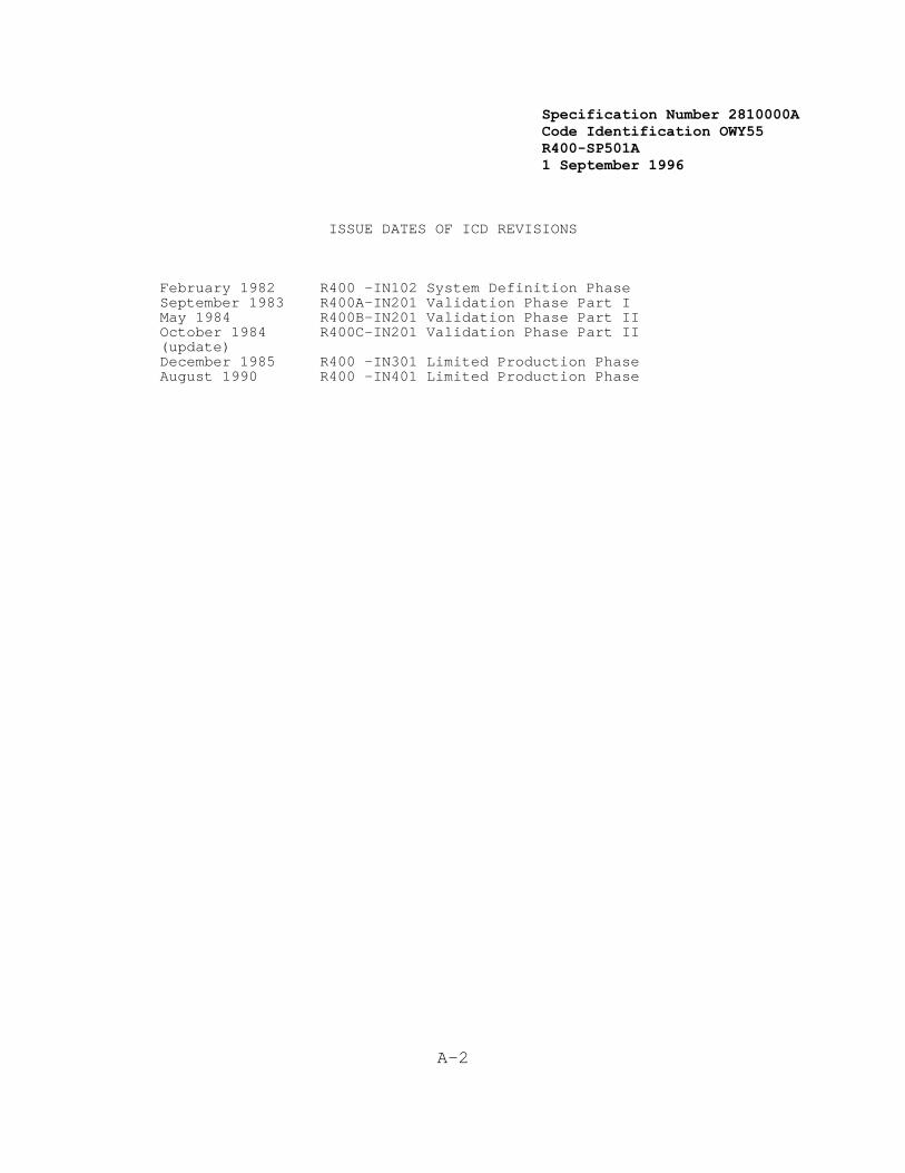
Specification Number 2810000ACode Identification OWY55 R400-SP501A 1 September 1996
A-2
ISSUE DATES OF ICD REVISIONS
February 1982 R400 -IN102 System Definition PhaseSeptember 1983 R400A-IN201 Validation Phase Part IMay 1984 R400B-IN201 Validation Phase Part IIOctober 1984 R400C-IN201 Validation Phase Part II(update)December 1985 R400 -IN301 Limited Production PhaseAugust 1990 R400 -IN401 Limited Production Phase

Specification Number 2810000ACode Identification OWY55 R400-SP501A 1 September 1996
A-3
1. INTRODUCTION
This interface Control Document (ICD) identifies the narrowbandcommunication requirements for both intra and inter NEXRAD Unitinterfaces.
Intra NEXRAD Unit communications consist of those links betweenequipment performing the Radar Product Generation (RPG) functions andequipment performing the Principal User Processor (PUP) functionsassociated with the RPG. Inter NEXRAD Unit communications consist ofthose links between selected equipment in different NEXRAD Units and/orequipment in a NEXRAD Unit and Principal User external systems and/orequipment in a NEXRAD Unit and Other Users.
1.1 Purpose
The purpose of this document is to define the requirements for theNEXRAD narrowband communications interfaces. For the NEXRAD Unitinterfaces, this document identifies applicable standards and definesthe protocol, syntax, and meaning of the binary data transmissionframes.
1.2 Scope
This ICD is not intended to serve as a tutorial document concerning theapplicable standards. That is, the reader is assumed to be generallyknowledgeable of the contents, terminology, etc., of the standards. This document maps the unique NEXRAD aspects of the narrowbandcommunications into the appropriate standard.
The remainder of this ICD consists of two sections and two appendices asfollows:
" Section 2.0 defines the NEXRAD interfaces and discusses theInternational Standards Organization (ISO) Open SystemInterconnection (OSI) Reference Model concept.
" Section 3.0 specifies the protocol and data formats for eachlevel of interface described in Section 2.0. The appropriatestandard is referenced where appropriate.
" Section 4.0 lists the applicable federal and internationalstandards and provides the sources for these standards.
" Section 5.0 contains a glossary of terms used in the NEXRADICD.
2. GENERAL INTERFACE CHARACTERISTICS
The first part of this section enumerates the classes of NEXRADcommunication lines and describes their functional characteristics. Thesecond part defines layers of NEXRAD interfaces based on the OSIReference Model. The layer concept is used because it helps tostructure and classify NEXRAD data transport protocols and thehierarchical structure is useful for determining the entire set ofNEXRAD communication interfaces. The layers defined explicitly in this
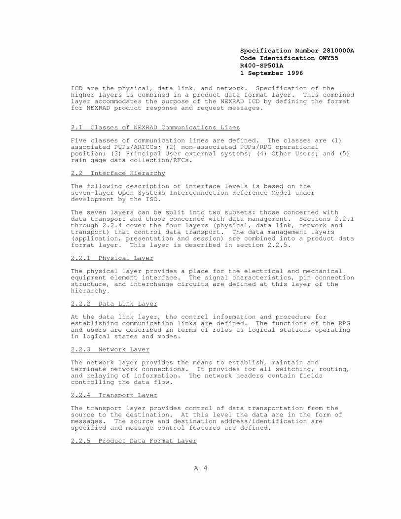
Specification Number 2810000ACode Identification OWY55 R400-SP501A 1 September 1996
A-4
ICD are the physical, data link, and network. Specification of thehigher layers is combined in a product data format layer. This combinedlayer accommodates the purpose of the NEXRAD ICD by defining the formatfor NEXRAD product response and request messages.
2.1 Classes of NEXRAD Communications Lines
Five classes of communication lines are defined. The classes are (1)associated PUPs/ARTCCs; (2) non-associated PUPs/RPG operationalposition; (3) Principal User external systems; (4) Other Users; and (5)rain gage data collection/RFCs.
2.2 Interface Hierarchy
The following description of interface levels is based on theseven-layer Open Systems Interconnection Reference Model underdevelopment by the ISO.
The seven layers can be split into two subsets: those concerned withdata transport and those concerned with data management. Sections 2.2.1through 2.2.4 cover the four layers (physical, data link, network andtransport) that control data transport. The data management layers(application, presentation and session) are combined into a product dataformat layer. This layer is described in section 2.2.5.
2.2.1 Physical Layer
The physical layer provides a place for the electrical and mechanicalequipment element interface. The signal characteristics, pin connectionstructure, and interchange circuits are defined at this layer of thehierarchy.
2.2.2 Data Link Layer
At the data link layer, the control information and procedure forestablishing communication links are defined. The functions of the RPGand users are described in terms of roles as logical stations operatingin logical states and modes.
2.2.3 Network Layer
The network layer provides the means to establish, maintain andterminate network connections. It provides for all switching, routing,and relaying of information. The network headers contain fieldscontrolling the data flow.
2.2.4 Transport Layer
The transport layer provides control of data transportation from thesource to the destination. At this level the data are in the form ofmessages. The source and destination address/identification arespecified and message control features are defined.
2.2.5 Product Data Format Layer
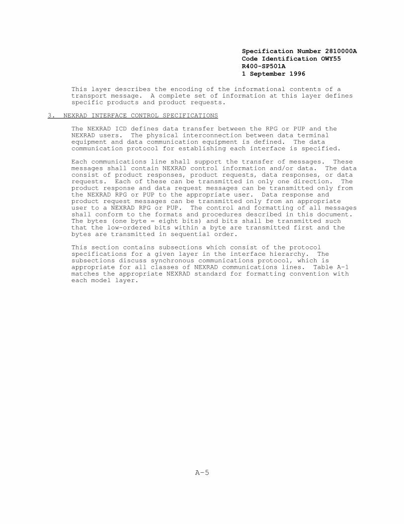
Specification Number 2810000ACode Identification OWY55 R400-SP501A 1 September 1996
A-5
This layer describes the encoding of the informational contents of atransport message. A complete set of information at this layer definesspecific products and product requests.
3. NEXRAD INTERFACE CONTROL SPECIFICATIONS
The NEXRAD ICD defines data transfer between the RPG or PUP and theNEXRAD users. The physical interconnection between data terminalequipment and data communication equipment is defined. The datacommunication protocol for establishing each interface is specified.
Each communications line shall support the transfer of messages. Thesemessages shall contain NEXRAD control information and/or data. The dataconsist of product responses, product requests, data responses, or datarequests. Each of these can be transmitted in only one direction. Theproduct response and data request messages can be transmitted only fromthe NEXRAD RPG or PUP to the appropriate user. Data response andproduct request messages can be transmitted only from an appropriateuser to a NEXRAD RPG or PUP. The control and formatting of all messagesshall conform to the formats and procedures described in this document. The bytes (one byte = eight bits) and bits shall be transmitted suchthat the low-ordered bits within a byte are transmitted first and thebytes are transmitted in sequential order.
This section contains subsections which consist of the protocolspecifications for a given layer in the interface hierarchy. Thesubsections discuss synchronous communications protocol, which isappropriate for all classes of NEXRAD communications lines. Table A-1matches the appropriate NEXRAD standard for formatting convention witheach model layer.

Specification Number 2810000ACode Identification OWY55 R400-SP501A 1 September 1996
27 * The SHEF format shall be used for data transmitted to NEXRAD. Theformats of all data transmitted from NEXRAD to the rain gage dataacquisition computers are the responsibility of the Government.
A-6
TABLE A-1 NEXRAD STANDARDS AND CONVENTIONS AT EACH INTERFACE LAYER Layer Class
1 2 3 4 5a 5b______________________________________________________
Product DataFormat V V SF V SH SF
Transport V V SF V V SF
Network X X X X X X
Data Link X X X X X X
Physical R R R R R R
V = VENDOR SpecifiedSF = Standard FormatsX = CCITT Recommendation X.25R = RS-449/RS-232-CSH = SHEF27
3.1 Physical Layer
This section specifies the interface standards for the data terminalequipment (DTE) and data communications equipment (DCE) interface. Italso provides general information concerning modem equipmentcharacteristics and communication link characteristics for NEXRAD.
3.1.1 DTE/DCE Interface
The DTE/DCE interface shall be specified by both EIA Standards RS-449and RS-232-C. All DTEs shall conform to RS-449. The DCEs may conformto RS-449 or to RS-232-C with adapters to RS-449. IndustrialElectronics Bulletin (IEB) No. 12 provides interconnection informationbetween RS-449 and RS-232-C. The following sections specify theelectrical and mechanical characteristics and the set of interchangecircuits for NEXRAD units in accordance with the standards.
3.1.1.1 Signal Characteristics
The general signal characteristics shall be defined by Section 2.0 ofEIA Standard RS-449, which requires EIA Standards RS-422 and RS-423(which have been revised as RS-422-A and RS-423-A, respectively) tospecify the electrical signal characteristics. Interconnection betweenRS-449 and RS-232-C is described in Section 2.1 of IEB No. 12.

Specification Number 2810000ACode Identification OWY55 R400-SP501A 1 September 1996
A-7
3.1.1.2 Mechanical Characteristics
The mechanical interface equipment and connectors specifications shallfollow Section 3.0 of RS-449. For interconnection with RS-232-C anadapter will be necessary. Refer to Section 2.3 of IEB No. 12 forinterconnection with the commonly used 25-pin connector.
3.1.1.3 Data Transmission Circuit Configuration
The standard data transmission configurations Type SR (Send-Receive) inRS-449 and the corresponding interface type D (RS-232-C) shall be usedfor NEXRAD. The interchange circuits for this configuration are asspecified in Section 5.0 and as defined in Section 4.0 of the respectivestandards. IEB No. 12 defines the correspondence of circuits betweenthe two standards.
3.1.2 Communication Line Facility
The general modem and communication link characteristics shall be asspecified in Section 3.7.4 of the NEXRAD Technical Requirements. Thetransmission line characteristics of each of the five classes ofnarrowband communications interfaces as defined in Section 2.1 arelisted in Table A-2.
TABLE A-2 NEXRAD TRANSMISSION LINE CHARACTERISTICS
Interface Link Type Rate (bps) Timing
Class 1 Dedicated Full Duplex 9600/4800 Synchronous
Class 2 Dial-Up Full Duplex 9600/4800 Synchronous
Class 3 Dedicated Full Duplex 9600/4800 Synchronous
Class 4 Dial-Up Full Duplex 9600/4800 Synchronous Dedicated Full Duplex 9600/4800 Synchronous
Class 5 Dial-Up Full Duplex 9600/4800 Synchronous
3.2 Data Link Layer
The data link layer shall control data transmission across the accesslink. Both the user data and control information shall be transferredacross the access link in transmission units called frames. The mainfunction of the link level protocol is to ensure that the level 3packets, which are contained within the link level field, shall crossthe access link error free.
3.2.1 Access Link for Synchronous Transmission
The access link protocol shall be Link Access Procedure, Balanced (LAPB)implemented for a single link procedure, and shall conform to Section 2of the 1984 or later CCITT Recommendation X.25, titled "Link Access
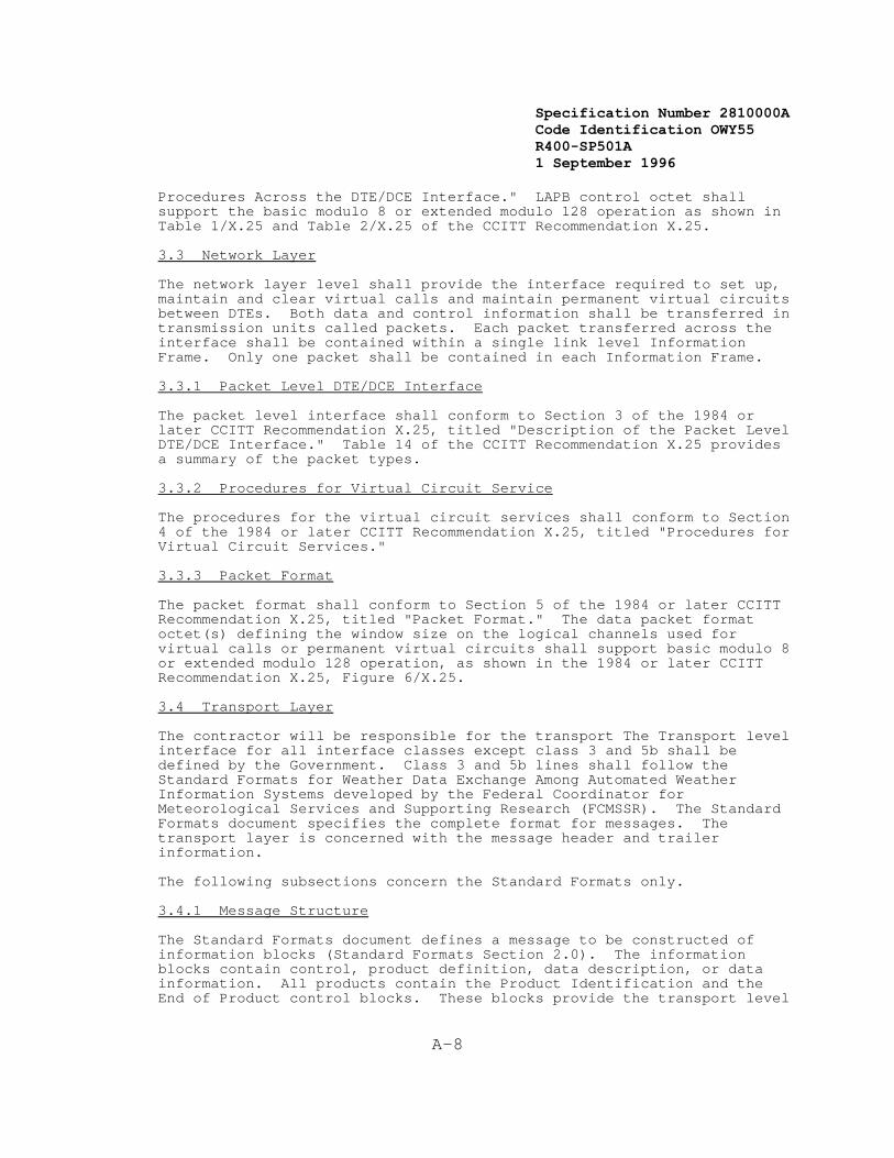
Specification Number 2810000ACode Identification OWY55 R400-SP501A 1 September 1996
A-8
Procedures Across the DTE/DCE Interface." LAPB control octet shallsupport the basic modulo 8 or extended modulo 128 operation as shown inTable 1/X.25 and Table 2/X.25 of the CCITT Recommendation X.25.
3.3 Network Layer
The network layer level shall provide the interface required to set up,maintain and clear virtual calls and maintain permanent virtual circuitsbetween DTEs. Both data and control information shall be transferred intransmission units called packets. Each packet transferred across theinterface shall be contained within a single link level InformationFrame. Only one packet shall be contained in each Information Frame.
3.3.1 Packet Level DTE/DCE Interface
The packet level interface shall conform to Section 3 of the 1984 orlater CCITT Recommendation X.25, titled "Description of the Packet LevelDTE/DCE Interface." Table 14 of the CCITT Recommendation X.25 providesa summary of the packet types.
3.3.2 Procedures for Virtual Circuit Service
The procedures for the virtual circuit services shall conform to Section4 of the 1984 or later CCITT Recommendation X.25, titled "Procedures forVirtual Circuit Services."
3.3.3 Packet Format
The packet format shall conform to Section 5 of the 1984 or later CCITTRecommendation X.25, titled "Packet Format." The data packet formatoctet(s) defining the window size on the logical channels used forvirtual calls or permanent virtual circuits shall support basic modulo 8or extended modulo 128 operation, as shown in the 1984 or later CCITTRecommendation X.25, Figure 6/X.25.
3.4 Transport Layer
The contractor will be responsible for the transport The Transport levelinterface for all interface classes except class 3 and 5b shall bedefined by the Government. Class 3 and 5b lines shall follow theStandard Formats for Weather Data Exchange Among Automated WeatherInformation Systems developed by the Federal Coordinator forMeteorological Services and Supporting Research (FCMSSR). The StandardFormats document specifies the complete format for messages. Thetransport layer is concerned with the message header and trailerinformation.
The following subsections concern the Standard Formats only.
3.4.1 Message Structure
The Standard Formats document defines a message to be constructed ofinformation blocks (Standard Formats Section 2.0). The informationblocks contain control, product definition, data description, or data information. All products contain the Product Identification and theEnd of Product control blocks. These blocks provide the transport level

Specification Number 2810000ACode Identification OWY55 R400-SP501A 1 September 1996
A-9
information.
3.4.2 Message Format
The Product Identification block is the first block of the message. This block contains the message header information necessary fortransport from source to destination. The End of Product block delimitsthe end of the message. Each block contains an optional lengthindicator and checksum (see Standard Formats Section 2.2). Also, eachblock contains a mode and submode number as defined in Standard FormatsSection 3.2.
3.4.2.1 Product Identification Block
The Product Identification Block contains the following fields:
" Originator Identification
" Classification
" Retention Time
" Product Identifier Code
" Product File Time.
These fields are defined in Figure 4.1 of the Standard Formats. Specific NEXRAD codes for the originator identification and productidentifier will be supplied by the government at a later date.
3.4.2.2 End of Product Block
The End of Product Block (Standard Formats Section 4.2) contains aparticular mode and submode combination (Mode 1, Submode 2) whichidentifies the end of the message. This block may also contain theoptional length indicator and checksum fields.
3.5 Product Data Format Layer
Product data formats for the RPG to PUP transmission (class 1 and 2),and for other users (class 4)shall be defined by the Government. Class5a, used for rain gage data collection, will not carry products andproduct requests; the format for rain gage data and messages transmittedto NEXRAD shall be specified by the Standard Hydrologic Exchange Format(SHEF); formats for data transmitted from NEXRAD shall be defined by theGovernment. For class 3, External Systems, and Class 5b, RFC's, theproduct data formats shall be specified by the Standard Formats.
The following subsections concern the Standard Formats only (unlessotherwise specified).
3.5.1 Product Definition
A specific Product Definition Block exists for each data category. TheProduct Definition Block contains information necessary to define thenature of the product.

Specification Number 2810000ACode Identification OWY55 R400-SP501A 1 September 1996
A-10
Specification Number 2810000ACode Identification OWY55 R400-SP501A 1 September 1996
A-11
3.5.2 Data Categories
The data categories for NEXRAD products are:
" Alphanumeric
" Raster Scan
" Vector Graphic
" Gridded Data
A specific data block is defined for each data category. A datadescription block (see Standard Formats Section 6.2) may precede thedata block. The data description block contains information describingthe data in the data block, if it is not inherent in the data blockitself.
3.5.2.1 Alphanumeric
Product requests and alphanumeric products shall be specified accordingto Standard Formats Section 8.0.
All alphanumeric information (whether or not the Standard Formats areemployed) shall follow the American National Standard Code forInformation Interchange (ASCII) as specified in ANSI X3.4-1977. Thecharacter structure for the ASCII code will follow ANSI X3.16-1976. Thebit sequencing within the ASCII code shall follow ANSI X3.15-1976. Onlythose sections of the latter two standards which refer to ANSI X3.4-1977shall apply.
3.5.2.2 Raster Scan
Raster Scan products shall be specified according to Section 9.0 of theStandard Formats.
3.5.2.3 Vector Graphic
Vector graphic products shall be specified according to Standard FormatsSection 7.0.
3.5.2.4 Gridded Data
Gridded Data products shall be specified according to Standard FormatsSection 10.0.

Specification Number 2810000ACode Identification OWY55 R400-SP501A 1 September 1996
A-12
4. REFERENCED DOCUMENTS
The following is a list of documents both explicitly and implicitlyreferenced in this ICD. The list contains the document number, titleand originating organization of each referenced document.
4.1 Federal
The Government Open System Interconnect Profile (GOSIP). GOSIPspecifies a subset of the OSI protocols, and may be described as aselection of a limited number of OSI protocols from each layer of theOSI Reference Model, as appropriate.
Source: National Institute of Standards and TechnologyU.S. Department of Commerce Gaithesburg, MD 20899
"Standard Hydrologic Exchange Format (SHEF) Version I", NOAA/NWS,Northwest River Forecast Center, Portland, Oregon, Nov. 18, 1982.
"An Explanation of the Standard Hydrologic Exchange Format (SHEF) andIts Implementation in the Central Region", NOAA Technical Memorandum NWSCR-67, Geoffrey Bonnin and Robert S. Cox, Jr., Missouri Basin RiverForecast Center, NWS, Kansas City, Missouri, April, 1983.
"The Posting of SHEF Data to the RFC Gateway Database", NOAA TechnicalMemorandum NWS CR-68, Geoffrey Bonnin, Missouri Basin River ForecastCenter, NWS, Kansas City, Missouri, April, 1983.
Source: NOAA - National Weather Service1325 East-West HighwaySilver Spring, MD 20910
4.2 National Communication Systems (NCS)
NCS TIB 81-1 Open Systems Interconnection (OSI) Reference Model(Nov. 1980)(ISO Draft Proposal (DP) 7498) January1981.
Source: Office of the ManagerNational Communications SystemAttn: NCS-TSWashington, D.C. 20305
4.3 American National Standards Institute (ANSI)
ANSI X3.4-1977 American National Standard Code for Information
ANSI X3.15-1976 American National Standard for Bit Sequencing of theAmerican National Standard Code for InformationInterchange in Serial-by-Bit Data Transmission
ANSI X3.16-1976 American National Standard Character Structure andCharacter Parity Sense for Serial-by-Bit DataCommunication in the American National Standard Code

Specification Number 2810000ACode Identification OWY55 R400-SP501A 1 September 1996
A-13
for Information Interchange
Source: ANSI, Inc.1430 BroadwayNew York, NY 10018
4.4 Electronic Industries Association (EIA)
EIA-RS-449 General Purpose 37 Position and 9 Position Interfacefor Data Terminal Equipment and Data Circuit-Terminating Equipment Employing Serial Binary DataInterchange.
EIA-RS-422-A Electrical Characteristics of Balanced Voltage DigitalInterface Circuits.
EIA-RS-423-A Electrical Characteristics of Unbalanced VoltageDigital Interface Circuits.
Industrial Electronics Application Notes on InterconnectionBulletin No. 12 Between Circuits Using RS-449 and RS-232-C.
EIA-RS-232-C Interface Between Data Terminal Equipment and DataCommunication Equipment Employing Serial Binary DataInterchange.
Source: Electronic Industries AssociationEngineering Department2001 I Street, N.W.Washington, D.C. 20006
4.5 Consultative Committee for International Telegraph and Telephone
CCITT Recommendation X.25 1980 and 1984, interface between Data TerminalEquipment (DTE) and Data Circuit-Terminating Equipment (DCE) forterminal operating in the packet mode on Public Data Networks.
Source: OMNICON, Inc.115 Park St., S.E.Vienna, VA 22180
4.6 Federal Coordinator
(FCM-S2-1982) Standard Formats for Weather Data Exchange AmongAutomated Weather Information Systems
Source: Federal Coordinator for MeteorologicalServices and Supporting BranchNational Oceanic and AtmosphericAdministrationU.S. Department of Commerce11426 Rockville PikeRockville, MD 20852

Specification Number 2810000ACode Identification OWY55 R400-SP501A 1 September 1996
A-14
5. GLOSSARY
ANSI - American National Standards Institute
ARTCC - Air Route Traffic Control Center
Block - A related set of bytes containing control information ordata. A block is a component of a message.
Byte - Eight contiguous bits.
CCITT - Consultative Committee for International Telegraph andTelephone
Data - Levels of interface concerned with the encoding,Management interpretation and use of information.Layers
Data - Levels of interface concerned with the transfer of data fromTransport source to destination.Layers
DCE - Data Circuit Terminating Equipment
DTE - Data Terminal Equipment
Frame - A segment of a bit stream bounded by a uniquely recognizablebit sequence and containing a specified number of bits orbytes of data.
Information - Contains both level two and level three information.Frame
ISO - International Standards Organization
LAPB - Link Access Procedure, Balanced
Message - The complete set of information transported from the sourceto the destination. A message may be a product, a productrequest, data, a data request, or NEXRAD controlinformation.
NEXRAD - Next Generation Weather Radar
OSI - Open Systems Interconnection
Packet - A communication block configured to permit independenthandling in a packet switching network. In most cases thismeans configured to be compatible with the CCITTRecommendation X.25.
Product - A collection of information that is self-contained andprovides a complete representation of a graphical image oran alphanumeric message.
PUP - Principal User Processing Functional Area

Specification Number 2810000ACode Identification OWY55 R400-SP501A 1 September 1996
A-15
RFC - River Forecast Center
RPG - Radar Product Generation Functional Area
SABM - Set Asynchronous Balanced Mode
SHEF - Standard Hydrometeorological Exchange Format
Specification Number 2810000ACode Identification OWY55 R400-SP501A 1 September 1996
B-1
APPENDIX B
1. Definition Of Terms
1.1 Adaptation Data
Generally, data related to a specific NEXRAD site. This data mayconsist of geographic boundaries, political boundaries, systemconfiguration, algorithm parameters, telephone numbers (auto dial), orother like data. Such data may be generated at either a centralizedlocation or locally within an RPG or PUP.
1.2 Alarm
An alarm is an attention getting notification, at the RDA and at theUCP, of RDA equipment failure or out of tolerance operating conditions.
1.3 Alert
An alert is the attention getting mechanism associated with receipt ofan alert message at an RPG or PUP operational position indicatingdetection of a significant change in a meteorological parameter orphenomenon.
1.4 Alphanumeric Products
Those products generated within the RPG functional area that present, inan alphanumeric format, some representation of information in baseproducts, derived products, or other alphanumeric products whethermanually or automatically generated (e.g., an alert message).
1.5 Associated PUP and RPG
A PUP and RPG combination that is connected by a dedicated full duplexcommunications circuit.
1.6 Availability (Achieved) - A(a)
The probability that the equipment associated with a specific NEXRADUnit (one RDA, one RPG, one associated PUP and all necessarycommunications), when used under stated conditions in an ideal supportenvironment, shall operate satisfactorily at any given time. Thecalculation of A(a) excludes supply downtime, waiting or administrativedowntime, and Government supplied communications equipment. It isexpressed as:
A(a) = MTBMA MTBMA+M
where:
MTBMA = Mean Time Between Maintenance Actions (failures orpreventive maintenance, including induced andno-defect maintenance).
M = Mean Active Maintenance Downtime resulting from both

Specification Number 2810000ACode Identification OWY55 R400-SP501A 1 September 1996
B-2
corrective and preventive maintenance actions(including induced and no-defect maintenance).
1.7 Availability (Inherent) - A(i)
The probability that the equipment associated with a specific NEXRADUnit (one RDA, one RPG, one associated PUP and all necessarycommunications), when used under stated conditions without considerationfor any scheduled or preventive maintenance and in an ideal supportenvironment, shall operate satisfactorily at any given time. Thecalculation of A(i) excludes preventive maintenance downtime, supplydowntime, waiting or administrative downtime and Government suppliedcommunications equipment. It is expressed as:
A(i) = f(all A(j))
where: The exact functional relationship is design dependent andshall be defined by the contractor's reliability model and,
A(j) is the availability of the "jth" CI and is given by
A(j) = MTBF(j) MTBF(j) + MTTR(j)
where:
MTBF(j) = Mean Time Between Failure of the jth CI[upper test (2o) per MIL-STD-781 C]
MTTR(j) = Mean Time To Repair the jth CI (see MTTR(CI))
1.8 Base Data
Those digital fields of reflectivity, mean radial velocity and spectrumwidth data in spherical (i.e.,rho,theta,phi) coordinates provided at thefinest resolution available from the RDA to the RPG. These dataresolutions are specified in Sections 3.7.1.2.2.1 and 3.7.1.2.2.2.
1.9 Base Products
Those products generated within the RPG functional area that presentsome representation of the base data. This representation may notnecessarily be either in full resolution or depict the full area ofcoverage. Base products can be used by a user to generate a graphicdisplay or perform further processing.
1.10 Catastrophic Failure
Any hardware or software condition that results in the inability toperform the minimally required RDA or associated RPG functions shown inSection 3.2.5 for at least one associated PUP.
1.11 Channel, Dual
The minimum equipment configuration needed to provide 100% redundancy
Specification Number 2810000ACode Identification OWY55 R400-SP501A 1 September 1996
B-3
(excluding the antenna assembly) in the capability to perform the singlechannel functions.
1.12 Channel, Single
The minimum equipment configuration needed to perform RDA key functions1, 2 and 3 as defined in Table 3-6.
1.13 Collocated
The data signalling rate and interconnecting cable characteristics,using the EIA-RS-422-A transmission standard, determine the distancethat NEXRAD equipment can be considered collocated. The RDA iscollocated with a RPG when the two are separated by not greater than 80meters of cable. The RPG is collocated with its Unit Control Position,PUPs, and/or RPG operational position (i.e. RPGOP) when they areseparated by not greater than 1200 meters of cable.
1.14 Configuration Item (CI)
A CI is any individual item of equipment or combination of equipmentitems needed to perform some portion of the operational NEXRADfunctional areas (i.e., RDA, RPG, PUP or communications). Furthermore,an independent CI is defined to have the following characteristics:
1. To fail without adversely affecting the performancecapability of another CI.
2. To be able to have power turned on/off without an adverseeffect on the performance capability of another CI.
3. The capability to have all external data, power, and/orcontrol lines removed or restored without an adverse effect on the performance capability of another CI.
1.15 Critical Altitude
The height above radar elevation of a meteorological phenomenon or theexpected height of the best radar signature of a meteorologicalphenomenon.
1.16 Derived Data Array Products
Those products generated automatically within the RPG functional areathat present, in a non-displayable format, some combination of baseproducts and derived products. These products are intended only fortransmission to systems external to the NEXRAD Unit for further processing.
1.17 Derived Products
Those products generated within the RPG functional area that representeither some combination of base products or a base product that has beenenhanced or otherwise changed by the use of manual or automated processing techniques. Derived products can be used for graphic displayof weather radar information or for further processing by a user.

Specification Number 2810000ACode Identification OWY55 R400-SP501A 1 September 1996
B-4
Specification Number 2810000ACode Identification OWY55 R400-SP501A 1 September 1996
B-5
1.18 Dwell Time
The time interval over which velocity and reflectivity samples are takento make the required estimates.
1.19 Expansion Capability
The capability to add CIs or LRUs to any NEXRAD Unit for the purpose ofincreasing its data acquisition, processing, and product distributioncapability. However, this addition shall not require:
1. New CIs or new LRUs within a CI that are not part of thelogistics system. A new CI that is form, fit and functionally compatible with an existing CI is permittedprovided it complies with items 3-5 of this definition.
2. Modification of an existing LRU or CI (the addition ofcables between preexisting connectors on existing CIs is notconsidered a modification. Also, the addition of LRUs to aCI will not be considered a modification if such LRUadditions are made by means of pre-existing wired connectorswithin a CI--e.g., the addition of a memory board to a CPUwhere one or more "slots" for such boards have beenreserved).
3. The writing of new software (operational or maintenance).
4. The modification of any existing operational or maintenancesoftware (changes made to the constants or parameter valuesare not considered modifications).
5. Addition or modification to any depot ATE capability.
1.20 Facility
The building(s) or enclosure(s) or that portion of the building(s) orenclosure(s) that houses some specific NEXRAD equipment.
1.21 Failure
Any hardware malfunction which degrades the performance of a CI belowits specified value. Failures are considered either relevant or non-relevant as defined below:
a. Relevant failures shall include all malfunctions that arenot specifically excluded as non-relevant. Each relevantfailure occurrence shall be included in all calculations ofreliability and availability.
b. A non-relevant failure is any failure which results fromfactors external to the CI or group of CIs under test. Non-relevant failures are not included in the determination ofMTBF or MTTR. Non-relevant failures shall be limited tothose failures which are due to the following causes:
1. Accidents
Specification Number 2810000ACode Identification OWY55 R400-SP501A 1 September 1996
B-6
2. Operator errors
3. Failure of another CI not under test, unless a patternof failures is detected.
4. Failure of test instrumentation or monitoringequipment, provided that it is not a component of theCI under test, that it does not cause the CI to beshut down or be interrupted, and that it does notcause an erroneous performance monitor reportindicating the CI performance is below its specifiedlevel.
5. Maintenance induced failures, unless attributable toequipment design.
6. Deviation from the mechanical, electrical, orenvironmental service specification, provided thatadequate monitoring or recording substantiate themagnitude of the deviation.
7. Software failures.
1.22 Interface
The total software and hardware, excluding Data Communication Equipment,in the NEXRAD system necessary to communicate between two devices eitherwithin the NEXRAD Unit or from the NEXRAD Unit to another system.
1.23 Interface Connection
A capability within the system (e.g., backplane slot) which, without anyother changes to the system, but provided with the software andhardware, will serve as an INTERFACE.
1.24 Line (Lowest) Replaceable Unit (LRU)
The minimum level of field replaceable equipment at any radar site orprincipal user site.
1.25 Local Facility
Those principal users located at one of the following types of location:WSFO, WSO, BWS, NOCD, TRACON, ATC Tower, or FSS.
1.26 Local Warning Site
An equipment site that performs the RDA, RPG, or PUP function for one ofthe principal users that has a unique need or data requirement. Whiledata from such sites will be available for other principal users, theneed for such data would not be a routine occurrence.
1.27 Maintenance Position
The location of unique NEXRAD equipment at the radar sites and/or usersites, from which maintenance actions are initiated and/or the results
Specification Number 2810000ACode Identification OWY55 R400-SP501A 1 September 1996
B-7
from such action can be observed.
1.28 Maximum Downtime (MDT)
The time interval between detection of a hardware failure in an RDA,RPG, or PUP equipment and the restoration of the appropriate functionalarea to a fully operational state for 90% of all CI failures, excludingsupply time and administrative downtime.
1.29 Mean Time Between Visits (MTBV)
The mean time between visits to effect equipment repairs, excludingpreventative maintenance and based on the concept that a visit is madeonly after redundant equipment failures have reduced the equipment at aradar site to its minimum operational configuration. This assumesequipment is at a location unattended by maintenance personnel.
1.30 Mean Time To Repair (NEXRAD Unit)
The NEXRAD Unit mean time to repair (MTTR) shall be the statistical meanof the distribution of repair times for a NEXRAD Unit. The summation ofactive repair times during a given period of time divided by the totalnumber of malfunctions during the same time interval.
1.31 Mean Time To Repair (MTTR(CI))
The statistical mean of the distribution of repair times for a CI. Thesummation of active repair times during a given period of time dividedby the total number of malfunctions during the same time interval.
1.32 Median Gain
That level over an angular region at which the probability is 50% thatthe observed or measured gain at any position of the antenna will beless than or equal to that level.
1.33 National Facility
Those principal users located at one of the following locations: NMC,NSSFC, AFGWC, an HC, or the SCC.
1.34 Network Site
A site that performs the RDA and/or RPG functions on a 24-hour day,7-day week basis. The products generated at a network site may not beactually utilized by the users on the same schedule; however, thesesites have a distinct advantage to all principal users. That is, datafrom such a site would probably be used, on a routine basis, by allprincipal users.
1.35 NEXRAD System
The summation of all hardware, software, facilities, communications,logistics, training, and staff, together with operations, training, andmaintenance procedures. The system includes both network sites andlocal warning sites (both CONUS and overseas).

Specification Number 2810000ACode Identification OWY55 R400-SP501A 1 September 1996
B-8
Specification Number 2810000ACode Identification OWY55 R400-SP501A 1 September 1996
B-9
1.36 NEXRAD Unit
The combination of one RDA, one RPG, all associated PUPS, and thenecessary communications to fully implement the operational capability.
1.37 Off-The-Shelf
Either equipment or software that is in current production or part ofthe original manufacturer's commercial product line, and supported bythe original manufacturer at the time of Limited Production Phasecontract award.
1.38 Operational Facility
Any local, regional, or national facility.
1.39 Other User
Any user not identified as a principal user.
1.40 Port
An INTERFACE, plus all required Data Communications Equipment (cables,modems, etc.) needed to communicate with another device, either withinor outside of the NEXRAD Unit.
1.41 Preview Area
An area on the alphanumeric or graphic displays for the viewing ofoperator entered data before physical modification of the displayoccurs.
1.42 Principal User
The National Weather Service, Air Weather Service, Naval OceanographyCommand, or Federal Aviation Administration.
1.43 Principal User Site
Site of the equipment necessary to perform the principal user function. May be collocated with another site (i.e., a radar site).
1.44 Principal User External System
An existing or planned principal user automated digital communicationsnetwork or other automated system with which one or more NEXRAD Units must interface. The known interfaces are: AFOS (NWS), CWP (FAA), MOC(AWS), and NEDS (NOC).
1.45 Radar Site
Site of a specific NEXRAD antenna. May be collocated with another site(i.e., a principal user site).
1.46 Regional Facility
Specification Number 2810000ACode Identification OWY55 R400-SP501A 1 September 1996
B-10
Those principal users located at one of the following locations: RFCs orARTCCs (CWSUs).
1.47 Repair Time
The repair time for configuration items shall include the total timerequired to detect and isolate the failure, to replace the CI or thefailed component, check out the repair, and return the item to fulloperational status (includes the time to restore the system, loadadaptation data, restore data base, etc., to its condition prior to thefailure).
1.48 Response Time
The time interval between completion of all needed manual actions andcompletion of the results of those actions. For example, if a usercalls up one product for display, the response time is the time intervalbetween making the last needed keystroke to call up the product andcompletion of the display of the resulting product (not just the startof display of a product).
1.49 Scan Period
The time required for a radar to complete a full 360 degree rotation inazimuth.
1.50 Site
The geographic location of some specific NEXRAD equipment.
1.51 Stability Test, 72-Hour
The stability test consists of continuous operation of the completeNEXRAD unit for a period of 72 hours. When a SYSTEM FAULT occurs, thetest will be extended to ensure that the last 6 hours of the test arefault free.
1.52 Startup
The process of initializing an RDA, RPG, or PUP without regard to itsprevious state.
1.53 Support Facility
A facility that provides some form of support primarily for the NEXRADSystem. This support may be in such areas as training, logistics,supply, or testing.
1.54 System Fault
A system fault is any malfunction which degrades NEXRAD unit performancebelow its specifications. Malfunctions arising from accidents, failuresof test instrumentation or monitoring equipment shall not be considereda system fault.
1.55 Throughput Time
Specification Number 2810000ACode Identification OWY55 R400-SP501A 1 September 1996
B-11
The time interval measured from the completion of the base datanecessary for the generation of a product until the product is displayedat an associated PUP for base, derived and alphanumeric products, orreceived at an associated PUP for derived data array products. Thistime interval includes transmission time but excludes RPG queue time.
1.56 Unit Control Position
The location of unique NEXRAD equipment at a radar site or a user sitefrom which normal system functions are initiated and system statusreports are observed for a NEXRAD Unit. It is important to distinguishbetween system functions and operational functions. The former includessuch actions as startup, restart, modifying local adaptation data, andmonitoring communication queue lengths. The latter includes suchactions as radar data interpretation, product generation ormodification, and message preparation.
1.57 Volume Scan
The process of completing all elevation angle scans in a specificscanning sequence.
1.58 Volume Scan Time
The time interval between the start of one volume scan and the start ofthe next volume scan.

Specification Number 2810000ACode Identification OWY55 R400-SP501A 1 September 1996
B-12
This Page Intentionally Left Blank

Specification Number 2810000ACode Identification OWY55 R400-SP501A 1 September 1996
C-1
APPENDIX C
ALGORITHMS
The algorithms required for the Limited Production Phase NEXRAD Systemare listed below and are available as a separate document, AlgorithmReport R400-AR401.
Algorithm Algorithm Required forNumber Title Full Load
2 Mesocyclone Detection x4 Storm Tracking x5 Storm Centroids x6 Vert. Integrated Liquid (VIL) x7 Velocity Azim. Display (VAD) x
8 Storm Position Forecast x 9 Storm Structure x 12 Hail x 13 Echo Top x
15 Severe Wx Probability x17 Precipitation Preprocessing18 Precipitation Rate19 Precipitation Accumulation20 Precipitation Adjustment
21 Precipitation Products22 Storm Segments x23 Turbulence x26 Tornado Vortex Detection x33 Combined Shear x

Specification Number 2810000ACode Identification OWY55 R400-SP501A 1 September 1996
C-2
This Page Intentionally Left Blank
Specification Number 2810000ACode Identification OWY55 R400-SP501A 1 September 1996
D-1
APPENDIX D
HYDROMETEOROLOGICAL PROCESSING FUNCTIONS
This appendix contains the Precipitation Detection Function and the RainGage Data Acquisition Function. The purpose of these functions is tocollect data necessary for the precipitation processing described in theNEXRAD Algorithm Report (NAR), R400A-AR201. The NAR contains thedescriptions for the PRECIPITATION PREPROCESSING, PRECIPITATION RATE,PRECIPITATION ACCUMULATION, PRECIPITATION ADJUSTMENT, and thePRECIPITATION PRODUCTS algorithms which utilize these data.
Specification Number 2810000ACode Identification OWY55 R400-SP501A 1 September 1996
D-2
1. Precipitation Detection Function
1.1 Functional Description
The Precipitation Detection Function processes each full volumereflectivity scan in order to perform three basic functions. It detectswhether precipitation has occurred within a 230-km radius of the NEXRADradar and assigns a Precipitation Category appropriate to the situation.It maintains a Precipitation Status Message which indicates theoperational mode, the equipment status, and the Precipitation Category. Finally, when precipitation is first detected, it transmits thePrecipitation Status Message to an off-site computer so that theoff-site system can initiate precipitation gage polling.
Precipitation is detected by comparing rain rates (using the same Z-Rrelationship as the RATE algorithm) to threshold values contained in thePrecipitation Threshold Table. Whenever the area covered by detectedprecipitation at any tilt exceeds the threshold value in thePrecipitation Threshold Table, it is assumed that precipitation existsand a Precipitation Category is assigned to the situation. Whensignificant precipitation is occurring, Precipitation Category 1 isassigned to the weather situation. When precipitation amounts and arealextent are small, Precipitation Category 2 is assigned. A PrecipitationCategory 1 remains in effect until 1 hour elapses with lightprecipitation , at which point Precipitation Category 2 is assigned, ora precipitation-free period of 1 hour occurs. Precipitation Category 2remains in effect until a precipitation-free period of 1 hour occurs orprecipitation Category 1 is detected. Precipitation Category 1 takesprecedence over Precipitation Category 2. When no precipitation isdetected, the Precipitation Category is 0.
The Precipitation Threshold Table includes a Nominal Clutter Area foreach row in the table. This allows the performance of the function tobe tuned to the clutter characteristics of individual NEXRAD sites,including the performance of any clutter filtering algorithm(s) appliedto the Reflectivity Factor data before this function processes them.
1.2 Processing Environment
It is assumed that several preprocessing steps will be applied to thereflectivity data before the data are input to the PrecipitationDetection Function (for example, clutter suppression). Care must betaken to ensure that these steps are accomplished without loss of dataquality or quantitative accuracy.
Some of the important preprocessing steps expected before data are inputto this function include:
" Oxygen absorption correction [function of antenna elevationangle, range, height of antenna, and the assumed atmosphericstate (probably the U.S. Standard Atmosphere)]
" Assignment of zero values to all reflectivities below aspecified/determined noise threshold
" Signal processing in ground clutter areas as specified by a
Specification Number 2810000ACode Identification OWY55 R400-SP501A 1 September 1996
D-3
clutter map to suppress ground clutter, as well as anomalouspropagation where possible, and other sources ofinterference, and
" Automatic calibration and quality control functions asdesirable and feasible.
Furthermore, this function assumes that the reflectivity data beinginput have been converted to equivalent reflectivity factor data,hereafter referred to as simply Reflectivity Factor data, using thestandard assumptions in the classical radar equation. In addition, itis assumed that correction has been applied to adjust for any knownbiases and losses resulting from the signal processing, alterations inequipment calibration, dry radome attenuation (eventually, wet radomeeffects may also be addressed in the preprocessing), and any other knownlosses.
The Precipitation Status Message produced by this function is requiredby the PREPROCESSING, RATE, ACCUMULATION, ADJUSTMENT, and PRODUCTSalgorithms in the Precipitation Processing Subsystem and the Rain GageData Acquisition Function.
1.3 Acquisition
Reflectivity Bins are intrinsic system parameters acquired directly fromthe radar.
Reflectivity Factor data are acquired from the NEXRAD base data andshould include clutter filtering and other quality control procedures tothe extent possible.
Elevation Angles are system adaptation parameters which may change withchanging scanning strategies.
The Multiplicative Z-R Coefficient and the Power Z-R Coefficient aresystem adaptation parameters which are also used by the RATE algorithm.
The Precipitation Threshold Table including the Tilt Domains, theNominal Clutter Areas, the Precipitation Categories, the PrecipitationRate Thresholds, and the Precipitation Area Thresholds are siteadaptation parameters based on empirical studies to assure thatsignificant precipitation events are not missed. They will be "finetuned" for each site.
The Precipitation Status Message is an output of this functionmaintained continuously for access by other algorithms (notably the RainGage Data Acquisition Function) as needed.
The radar ID is a site adaptation parameter.
The Time Stamp is acquired from the NEXRAD system clock in GreenwichMean Time.
The Last Precipitation Detected Time is computed by the PrecipitationDetection Function.

Specification Number 2810000ACode Identification OWY55 R400-SP501A 1 September 1996
D-4
1.4 Computation
1.4.1 Notation
Ap = Area of precipitation detected at a particularElevation Angle
Z = Reflectivity Factor value in dBZ at a particular range(r) and azimuth (az)
r = Range to nearest point of a particular ReflectivityBin (km)
az = Azimuth of a particular Reflectivity Bin (degrees)
dr = Range resolution (bin size) of a particularReflectivity Bin (km)
da = Azimuthal resolution (beam width) of a particularReflectivity Bin (degrees)
Tp = Precipitation Rate Threshold in dBR for a particularrow in the Precipitation Threshold Table
a = Multiplicative coefficient in the Z-R relationship
b = Power coefficient in the Z-R relationship
TA = Precipitation Area Threshold in km2 for a particularrow in the Precipitation Threshold Table
TN = Nominal Clutter Area in km2 for a particular row inthe Precipitation Threshold Table
1.4.2 Symbolic Formula
First Set Ap = 0.0.
For All Reflectivity Bins (i.e., all r and az)
If Z(r,az)-10 log a > Tpb
Then Ap = Ap + Bda [(dr)2 + 2r dr]
360
This computation proceeds by processing each individual Elevation Anglewithin the Tilt Domain. The Precipitation Rate Threshold (Tp) in thecomputation is defined separately for each entry in the PrecipitationThreshold Table presuming the Elevation Angle falls within the specifiedTilt Domain for a table entry.
If Ap > TN + TA, assign the Precipitation Category indicated by thePrecipitation Threshold Table. Precipitation Category 1 has priority
Specification Number 2810000ACode Identification OWY55 R400-SP501A 1 September 1996
D-5
over Precipitation Category 2.
Once Precipitation Category 1 or Precipitation Category 2 is assigned,it remains in effect until the end of one precipitation-free hour. OncePrecipitation Category 2 is assigned, it remains in effect untilsuperseded by Precipitation Category 1 or until the end of oneprecipitation-free hour. The Precipitation Detection Function must beexecuted for each scan, regardless of the current PrecipitationCategory, in order to identify the existence of a precipitation-freehour, the initiation of precipitation, or a change in PrecipitationCategory.
1.5 Distribution
The Precipitation Status Message is transmitted to a Rain Gage DataAcquisition Computer (RGDAC) whenever precipitation is first detected. This allows the RGDAC to initiate hourly polling of rain gages. Oncegage polling is initiated, the RGDAC monitors the Precipitation StatusMessage each time it transmits new gage data to the Rain Gage DataAcquisition Function so that it knows when gage polling can besuspended.
The Precipitation Status Message is used in the PREPROCESSING, RATE,ACCUMULATION, ADJUSTMENT, and PRODUCTS algorithms in the PrecipitationProcessing Subsystem and the Rain Gage Data Acquisition Function.
1.6 Definitions
Reflectivity Bins - Grid cells for Reflectivity Factor data beinginput to this function. Data are required fromall elevation angles specified by the ElevationAngles.
Elevation Angles - Elevation angles from which Reflectivity Factordata are being input to the PrecipitationDetection Function. The elevations used willvary from site to site.
Reflectivity - Equivalent reflectivity factor data (in dBZ)Factor
Multiplicative - Multiplicative coefficient in Z-R conversion.Z-R Coefficient
Power Z-R - Power coefficient in the Z-R conversionCoefficient equation
Precipitation - Table of threshold values for precipitationThreshold detection. The table is composed of fiveTable columns: Tilt Domain, Precipitation Rate
Threshold, Nominal Clutter Area, PrecipitationArea Threshold, and the Precipitation Category. The table can have at most 50 rows and shall beadaptation data.
Specification Number 2810000ACode Identification OWY55 R400-SP501A 1 September 1996
D-6
An example table follows:
Tilt Precip. Nominal Precip. Precip.Domain Rate Clutter Area Category
Threshold Area Threshold(degrees) (dBR) (km2) (km2) 0 - 2 -3 20 20 20 - 4 1 15 10 12 - 4 -3 5 20 2
Consider a single volume scan at an elevationangle of 1o. If the area with ReflectivityFactor greater than or equal to an equivalentrain rate of -3 dBR exceeds 40 km2, thenPrecipitation Category 2 has been reached.
Consider an elevation angle of 3o within thesame volume scan. If the area with ReflectivityFactor greater than or equal to an equivalentrain rate of 1 dBR exceeds 25 km2, thenPrecipitation Category 1 has been reached. Precipitation Category 2 would also be ineffect, but since Precipitation Category 1 ismore significant, it would take precedence.
Tilt Domain - Range of Elevation Angles in degrees for which arow in the Precipitation Threshold Tableapplies.
Precipitation - Minimum rainfall rate (in dBR) for aRate Threshold Reflectivity Bin to count toward the
precipitation area for a particular row in thePrecipitation Threshold Table.
Precipitation - Minimum areas (in km2) covered by precipitationArea Threshold in the Precipitation Threshold Table.
Radar ID - Identifier for the NEXRAD radar site.
Precipitation - The Precipitation Status Message shall beStatus generated each time the Precipitation DetectionMessage Function is run and shall be composed of the
following items: radar ID, Time Stamp, LastPrecipitation Detected Time, PrecipitationCategory currently in effect, number of gages ingage data base, and time of last update to gagedata base.
Time Stamp - Time of occurrence of Precipitation StatusMessage in GMT.
Last - Time Stamp when precipitation was last detected.Precipitation This shall be updated every full volumeDetected Time reflectivity scan which detects precipitation.
Nominal - Area (in km2) normally produced by clutter with
Specification Number 2810000ACode Identification OWY55 R400-SP501A 1 September 1996
D-7
Clutter Area a Reflectivity Factor equivalent to thePrecipitation Rate Threshold for a particularrow in the Precipitation Threshold Table.
Precipitation - A coded value equal to 0, 1, or 2 for each rowCategory in the Precipitation Threshold Table giving the
Precipitation Category which has been reachedwhen the area of detected precipitation exceedsthe sum of the Precipitation Area Threshold plusthe Nominal Clutter Area.
0 = No precipitation detected1 = Significant precipitation detected2 = Light precipitation detected
1.7 Limitations
If any scan mode in the NEXRAD system fails to meet the requirements ofTable D-1, there can be no assurance that the Precipitation DetectionFunction will detect precipitation; i.e., the NEXRAD site may completelyfail to recognize precipitation occurrence. Since the PrecipitationProcessing Subsystem assumes that no precipitation is occurring if nonehas been detected by this function, precipitation accumulation estimateswill not be meaningful if this function fails to detect precipitation. In addition, if any scan mode does not meet the requirements of TableD-1, there can be no assurance that the category of precipitation (0, 1or 2) as assigned by this function is representative of currentconditions. Since the data requirements for the PrecipitationProcessing Subsystem during precipitation periods are more stringentthan those specified in Table D-1 and because they are categorydependent (see tables within the Precipitation Processing Subsystem,NEXRAD Algorithm Report), failure of the Precipitation DetectionFunction to properly assign the Precipitation Category could result inmeaningless precipitation estimates._______________________________________________________________________
TABLE D-1 MINIMAL SCAN MODE REQUIREMENTS NECESSARY FOR DETECTINGPRECIPITATION
Scan Characteristic Requirements
Range 230 km or moreRange Resolution 2 km or lessAzimuthal Coverage 360o
Azimuthal Resolution 2o or lessTilts and Repetition Lowest two tilts required by Precipitation
Processing Subsystem (see PREPROCESSINGalgorithm) at least every 10 minutes. Fourlowest tilts required by PrecipitationProcessing Subsystem at least every 30 minutes.
________________________________________________________________________
1.8 Future Developments
Due to the limitation cited above, the Precipitation Threshold Tablewill require fine tuning for best performance at each site using actual
Specification Number 2810000ACode Identification OWY55 R400-SP501A 1 September 1996
28 SHEF:1. "Standard Hydrologic Exchange Format (SHEF) Version I," NOAA/NWS,
Northwest River Forecast Center, Portland, Oregon, Nov. 18, 1982.
2. "An Explanation of the Standard Hydrologic Exchange Format (SHEF)and Its Implementation in the Central Region," NOAA TechnicalMemorandum NWS CR-67, Geoffrey Bonnin and Robert S. Cox, Jr.,Missouri Basin River Forecast Center, NWS, Kansas City, Missouri,April, 1983.
3. "The Posting of SHEF Data to the RFC Gateway Data Base," NOAATechnical Memorandum NWS CR-68, Geoffrey Bonnin, Missouri BasinRiver Forecast Center, NWS, Kansas City, Missouri, April, 1983.
D-8
NEXRAD data.
2. Rain Gage Data Acquisition Function
2.1 Functional Description
The Rain Gage Data Acquisition Function serves one primary function--itmaintains a data base of precipitation gage reports which aretransmitted to the NEXRAD site by one or more external computer systems. These gage data are reported in a format known as the StandardHydrometeorological Exchange Format (SHEF). The detailed description ofthe SHEF data format is contained in the three references cited below.28 The gage data are used by the ADJUSTMENT algorithm of the PrecipitationProcessing Subsystem which computes hourly accumulations for each gageusing the "raw" observations contained in the gage data base.
In addition to its primary function of parsing incoming SHEF data andposting it to the data base, this function responds to two other classesof incoming messages. The first class is a request for informationwhich has two forms: 1) a request for status which this functionresponds to by transmitting the precipitation status to the externalmachine which made the request, and 2) a request for the list of gagesin the gage data base which this function responds to by transmitting atable of Gage Identifiers, Gage Latitudes, and Gage Longitudes to therequesting machine.
The second class of incoming messages controls the gage data baseitself. It consists of a number of input lines which add, delete, orchange the characteristics of gages in the gage data base. The intentis to allow an external computer to maintain the data base of gages ateach NEXRAD site without manual intervention at the NEXRAD site itself.
A summary of incoming message formats is contained in Table D-2. TheSHEF format is a general format for transmission of all types ofhydrometeorological data. This function only requires precipitationdata in general, specifically only those PEDTSEP codes listed in TableD-3, and Duration Code Variable Specifiers listed in Table D-4.
The precipitation data managed by this data base are of two basic types:incremental and accumulation. Incremental reports give a precipitation

Specification Number 2810000ACode Identification OWY55 R400-SP501A 1 September 1996
D-9
accumulation (in inches or millimeters) for a specified duration. Allof the PEDTSEP codes in Table D-3 which begin with "PP" are incrementalreports. Incremental reports require that the duration be specifiedeither within the PEDTSEP code itself (e.g., PPH for hourly) or by useof a Duration Code Variable Specifier as indicated in Table D-4 (e.g.,DVN18/PPV for an 18-minute duration). Note that the SHEF format has atime resolution of 1 minute at best.
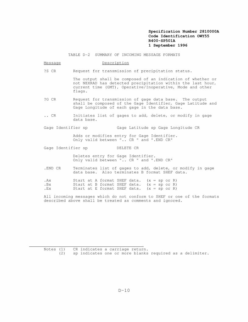
Specification Number 2810000ACode Identification OWY55 R400-SP501A 1 September 1996
D-10
TABLE D-2 SUMMARY OF INCOMING MESSAGE FORMATS
Message Description
?S CR Request for transmission of precipitation status.
The output shall be composed of an indication of whether ornot NEXRAD has detected precipitation within the last hour,current time (GMT), Operative/Inoperative, Mode and otherflags.
?G CR Request for transmission of gage data base. The outputshall be composed of the Gage Identifier, Gage Latitude andGage Longitude of each gage in the data base.
.. CR Initiates list of gages to add, delete, or modify in gagedata base.
Gage Identifier sp Gage Latitude sp Gage Longitude CR
Adds or modifies entry for Gage Identifier. Only valid between ".. CR " and ".END CR"
Gage Identifier sp DELETE CR
Deletes entry for Gage Identifier.Only valid between ".. CR " and ".END CR"
.END CR Terminates list of gages to add, delete, or modify in gagedata base. Also terminates B format SHEF data.
.Ax Start at A format SHEF data. (x = sp or R)
.Bx Start at B format SHEF data. (x = sp or R)
.Ex Start at E format SHEF data. (x = sp or R)
All incoming messages which do not conform to SHEF or one of the formatsdescribed above shall be treated as comments and ignored.
_______________________________________________Notes (1) CR indicates a carriage return.
(2) sp indicates one or more blanks required as a delimiter.

Specification Number 2810000ACode Identification OWY55 R400-SP501A 1 September 1996
29 Notes:"x" is used for "any character"
1. Other "a" codes for periods longer than 24 hours exist, but need notbe posted to the NEXRAD data base.
2. Provision should be made to expand the valid list of "a" codes aboveto include up to 20 values.
D-11
TABLE D-3 SUMMARY OF VALID PEDTSEP CODES
Code29 Description
PCPCIPCIRxPCIRxZPCIRxZZPCIZZ All of these codes are logicallyPCIZZZ equivalent -- meaning "instantaneousPCIZZZZ observed precipitation accumulator".PCZ All other codes beginning with PCPCZRx are invalid.PCZRxZPCZRxZZPCZZZPCZZZZPCZZZZZ
PPPPZPPZRx All of these codes are logically equivalentPPZRxZ meaning "observed incremental precipitation".PPZRxZ The increment duration is assumed 24 hours.PPZRxZZPPZZZPPZZZZPPZZZZZ
PPVPPVRx All of these codes are logically equivalentPPVRxZ meaning "observed incremental precipitation".PPVRxZZ The increment duration is specified by aPPVZZ preceding "DVx" code. If no "DVx" code hasPPVZZZ been specified, the data are presumedPPVZZZZ invalid.
PPaPPaRx All of these codes are logically equivalentPPaRxZ meaning "observed incremental precipitation."PPaRxZZ The increment duration is specified by "a"PPaZZ which must be one of the following:PPaZZZPPaZZZZ
"a" = U for one minute C for 15 minutesJ for 30 minutes H for one hour
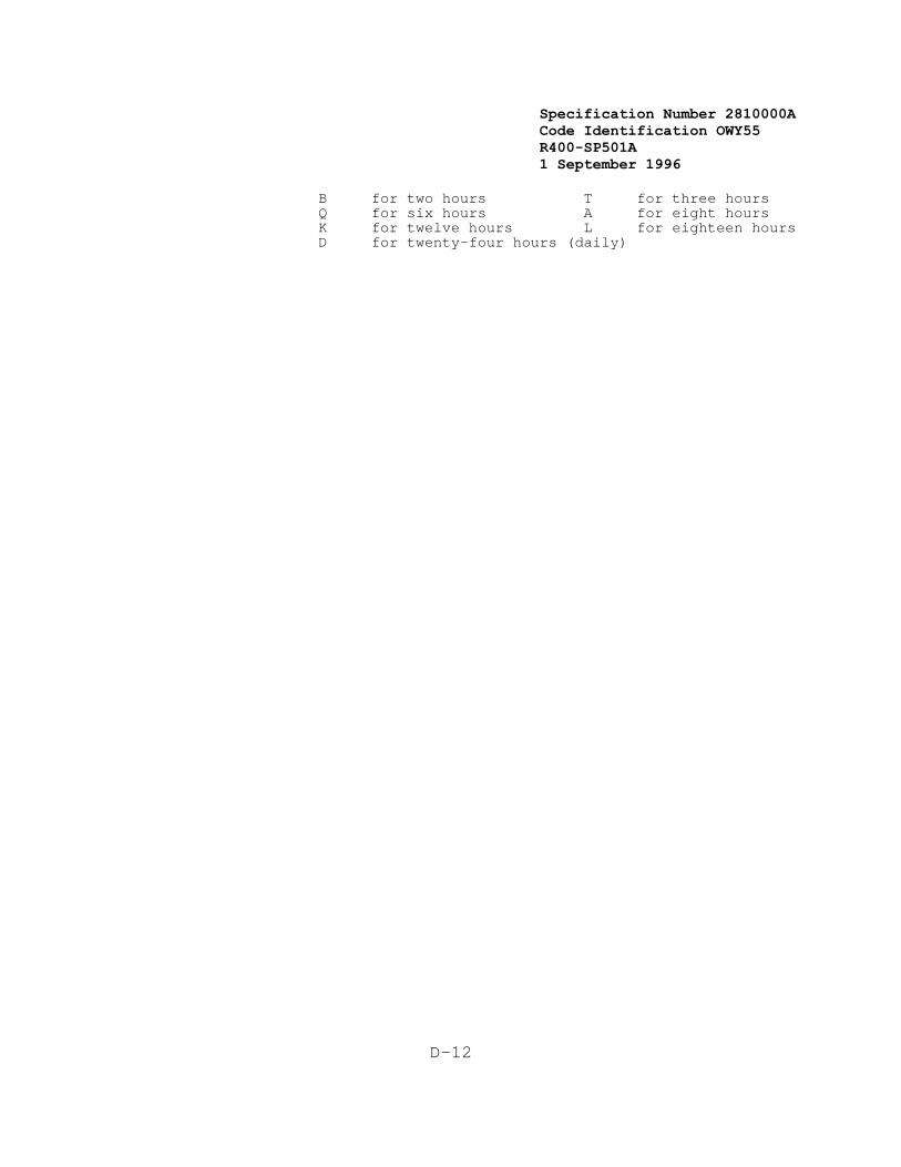
Specification Number 2810000ACode Identification OWY55 R400-SP501A 1 September 1996
D-12
B for two hours T for three hoursQ for six hours A for eight hoursK for twelve hours L for eighteen hoursD for twenty-four hours (daily)
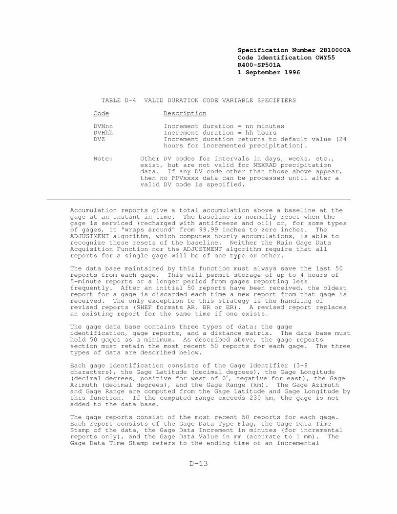
Specification Number 2810000ACode Identification OWY55 R400-SP501A 1 September 1996
D-13
TABLE D-4 VALID DURATION CODE VARIABLE SPECIFIERS
Code Description
DVNnn Increment duration = nn minutesDVHhh Increment duration = hh hoursDVZ Increment duration returns to default value (24
hours for incremented precipitation).
Note: Other DV codes for intervals in days, weeks, etc.,exist, but are not valid for NEXRAD precipitationdata. If any DV code other than those above appear,then no PPVxxxx data can be processed until after avalid DV code is specified.
______________________________________________________________________________
Accumulation reports give a total accumulation above a baseline at thegage at an instant in time. The baseline is normally reset when thegage is serviced (recharged with antifreeze and oil) or, for some typesof gages, it "wraps around" from 99.99 inches to zero inches. TheADJUSTMENT algorithm, which computes hourly accumulations, is able torecognize these resets of the baseline. Neither the Rain Gage DataAcquisition Function nor the ADJUSTMENT algorithm require that allreports for a single gage will be of one type or other.
The data base maintained by this function must always save the last 50reports from each gage. This will permit storage of up to 4 hours of5-minute reports or a longer period from gages reporting lessfrequently. After an initial 50 reports have been received, the oldestreport for a gage is discarded each time a new report from that gage isreceived. The only exception to this strategy is the handling ofrevised reports (SHEF formats AR, BR or ER). A revised report replacesan existing report for the same time if one exists.
The gage data base contains three types of data: the gageidentification, gage reports, and a distance matrix. The data base musthold 50 gages as a minimum. As described above, the gage reportssection must retain the most recent 50 reports for each gage. The threetypes of data are described below.
Each gage identification consists of the Gage Identifier (3-8characters), the Gage Latitude (decimal degrees), the Gage Longitude(decimal degrees, positive for west of 0o, negative for east), the GageAzimuth (decimal degrees), and the Gage Range (km). The Gage Azimuthand Gage Range are computed from the Gage Latitude and Gage Longitude bythis function. If the computed range exceeds 230 km, the gage is notadded to the data base.
The gage reports consist of the most recent 50 reports for each gage. Each report consists of the Gage Data Type Flag, the Gage Data TimeStamp of the data, the Gage Data Increment in minutes (for incrementalreports only), and the Gage Data Value in mm (accurate to 1 mm). TheGage Data Time Stamp refers to the ending time of an incremental
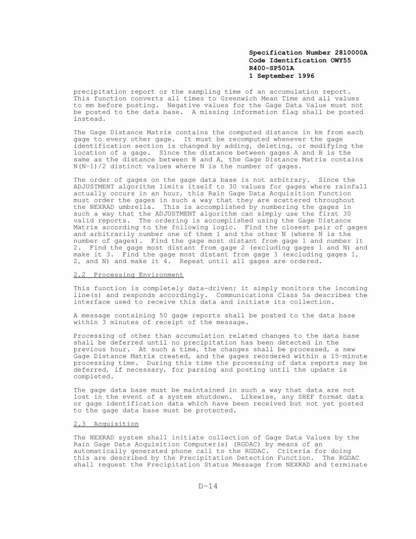
Specification Number 2810000ACode Identification OWY55 R400-SP501A 1 September 1996
D-14
precipitation report or the sampling time of an accumulation report. This function converts all times to Greenwich Mean Time and all valuesto mm before posting. Negative values for the Gage Data Value must notbe posted to the data base. A missing information flag shall be postedinstead.
The Gage Distance Matrix contains the computed distance in km from eachgage to every other gage. It must be recomputed whenever the gageidentification section is changed by adding, deleting, or modifying thelocation of a gage. Since the distance between gages A and B is thesame as the distance between B and A, the Gage Distance Matrix containsN(N-1)/2 distinct values where N is the number of gages.
The order of gages on the gage data base is not arbitrary. Since theADJUSTMENT algorithm limits itself to 30 values for gages where rainfallactually occurs in an hour, this Rain Gage Data Acquisition Functionmust order the gages in such a way that they are scattered throughoutthe NEXRAD umbrella. This is accomplished by numbering the gages insuch a way that the ADJUSTMENT algorithm can simply use the first 30valid reports. The ordering is accomplished using the Gage DistanceMatrix according to the following logic. Find the closest pair of gagesand arbitrarily number one of them 1 and the other N (where N is thenumber of gages). Find the gage most distant from gage 1 and number it2. Find the gage most distant from gage 2 (excluding gages 1 and N) andmake it 3. Find the gage most distant from gage 3 (excluding gages 1,2, and N) and make it 4. Repeat until all gages are ordered.
2.2 Processing Environment
This function is completely data-driven; it simply monitors the incomingline(s) and responds accordingly. Communications Class 5a describes theinterface used to receive this data and initiate its collection.
A message containing 50 gage reports shall be posted to the data basewithin 3 minutes of receipt of the message.
Processing of other than accumulation related changes to the data baseshall be deferred until no precipitation has been detected in theprevious hour. At such a time, the changes shall be processed, a newGage Distance Matrix created, and the gages reordered within a 15-minuteprocessing time. During this time the processing of data reports may bedeferred, if necessary, for parsing and posting until the update iscompleted.
The gage data base must be maintained in such a way that data are notlost in the event of a system shutdown. Likewise, any SHEF format dataor gage identification data which have been received but not yet postedto the gage data base must be protected.
2.3 Acquisition
The NEXRAD system shall initiate collection of Gage Data Values by theRain Gage Data Acquisition Computer(s) (RGDAC) by means of anautomatically generated phone call to the RGDAC. Criteria for doingthis are described by the Precipitation Detection Function. The RGDACshall request the Precipitation Status Message from NEXRAD and terminate
Specification Number 2810000ACode Identification OWY55 R400-SP501A 1 September 1996
D-15
data acquisition based on this information.
The Gage Identifier, Gage Latitude, and Gage Longitude are contained inmessages transmitted to NEXRAD by the RGDAC. These are retained by thegage data base.
The Gage Azimuth and Gage Range are computed by this function andretained in the gage data base.
The Gage Data Type Flag, Gage Data Time Stamp, Gage Data Increment, andGage Data Value are received by NEXRAD from the RGDAC. They shall bestored in the gage data base maintained by this function.
The Gage Distance Matrix is computed by this function for use by theADJUSTMENT algorithm and for ordering the gages within the gage database. All data received from the RGDAC will be in the SHEF format.
2.4 Data Summary
The entire gage data base including the Gage Identifier, Gage Latitude,Gage Longitude, Gage Range, Gage Azimuth, and Gage Distance Matrix; andall of the data reports which include Gage Data Type Flag, Gage DataTime Stamp, Gage Data Increment and Gage Data Value are continuouslymaintained by this function.
Precipitation Status Message, Gage Identifiers, Gage Latitudes, and Gage Longitudes may be transmitted by this function.
2.5 Definitions
Gage Identifier = A 3 to 8-character identifier for a gage.
Gage Latitude = Latitude in decimal degrees (positive for north)of a gage.
Gage Longitude = Longitude in decimal degrees (positive for westof 0o, negative for east) of a gage.
Gage Range = Computed range from NEXRAD antenna in km for agage (accurate to 0.1 km).
Gage Azimuth = Azimuth in decimal degrees from NEXRAD to a gage
(accurate to 0.1 degrees).
Gage Data Type = Identifies reporting type-incremental orFlag accumulation.
Gage Data = Time of occurrence of gage value in Greenwich Time Stamp Mean Time accurate to 1 minute. For incremental
reports = time of end of increment.
Gage Data = Increment length in minutes for incrementalIncrement precipitation reports.
Gage Data Value = Reported value in mm. This is an incrementalvalue for incremental reports or a total

Specification Number 2810000ACode Identification OWY55 R400-SP501A 1 September 1996
D-16
accumulation for accumulation reports. Accuracyis to within 1 mm.
Gage Distance = Matrix containing distances from each gage toMatrix every other gage in km (accurate to 0.1 km).
Precipitation = See Precipitation Detection Function Status Message

Specification Number 2810000ACode Identification OWY55 R400-SP501A 1 September 1996
D-17
This Page Intentionally Left Blank
Specification Number 2810000ACode Identification OWY55 R400-SP501A 1 September 1996
E-1
APPENDIX ENEXRAD PRODUCTS
This Appendix lists the NEXRAD products required to be implementedduring the Limited Production Phase. Table E-1 provides a summary foreach product of: the area of coverage; product resolution; frequency ofproduct generation for full load sizing; throughput time requirement;response time requirement for one-time product requests; and thefrequency of product archival for full load sizing. The final form ofany product is subject to Government approval.
1. Reflectivity
This product shall provide the reflectivity data displayable as animage.1 Variations of the product shall be organized to provide variousareas of coverage and display resolutions. The product shall begenerated for any azimuth scan at a single elevation angle based on userrequirements. Each scan shall be updated once per volume scan time.2 Each product shall be available for both 8 and 16 reflectivity datalevels. Each product shall include annotations for the product name,radar ID, time and date of scan, data level code, elevation angle,maximum data value (dBZ), radar position, radar elevation above MSL, andradar operational mode.
2. Mean Radial Velocity
This product shall provide the mean radial velocity data displayable asan image. Variations of the product shall be organized to providevarious areas of coverage and display resolution. The product shall begenerated for any azimuth scan at a single elevation angle based on userrequirements. Each scan shall be updated once per volume scan time. Each product shall include both 8 and 16 mean radial velocity datalevels. Each product shall include annotations for the product name,radar ID, time and date of scan, data level code, elevation angle,maximum data value detected (knots, positive and negative), radarposition, radar elevation above MSL, and radar operational mode.
3. Spectrum Width
This product shall provide the radial velocity spectrum width datadisplayable as an image. Variations of the product shall be organizedto provide various areas of coverage and display resolutions. Theproduct shall be generated for any azimuth scan at a single elevationangle based on user requirements. Each scan shall be updated once pervolume scan time. Each product shall be available for 8 spectrum widthdata levels. Each product shall include annotations for the productname, radar I.D., time and date of scan, data level code, elevationangle, maximum data value detected (knots), radar position, radarelevation above MSL, and radar operational mode.
____________________________________________1 Defines the form of presentation on a graphic display; not
necessarily the form of transmission.
Specification Number 2810000ACode Identification OWY55 R400-SP501A 1 September 1996
E-2
2 Defined in Appendix B.
4. Combined Shear
This product shall provide the combined (radial and azimuthal) shear ofthe mean radial velocity for a 230 km x 230 km area centered at theradar position. The shear information presented in this product shallbe the output of the Combined Shear Algorithm. It shall be presented asa displayable image of shear values containing 16 data levels. Thecapability to establish the product resolution shall be a UCP function. This product shall be produced for one elevation angle, as selected atthe UCP, with the lowest elevation angle as the default. This productshall be updated once per volume scan time.
This product shall include annotations for product name, radar ID, dateand time of elevation scan, elevation angle, data level code, positionand value of maximum shear value, radar position, radar elevation aboveMSL, product resolution and radar operational mode. Upon user request,all site adaptable parameters identified as inputs to the algorithmsused to generate data for this product shall be available at thealphanumeric display.
5. Combined Shear Contour
This product shall provide contours of the combined shear and shall beproduced by contouring the output of the Combined Shear Algorithm usedto produce the Combined Shear Product. The contouring interval(s) shallbe site adaptable.
This product shall be displayable alone or as an overlay on reflectivityor velocity base products. This product shall be updated once pervolume scan time.
This product shall contain annotations for the product name, radar ID,time and date of scan, position and value of the maximum shear value,elevation angle, radar position, radar elevation above MSL, radaroperational mode, spatial resolution of contoured shear data andcontouring interval(s). Upon user request, all site adaptableparameters identified as inputs to the algorithm used to generate datafor this product shall be available at the alphanumeric display.
6. Composite Reflectivity
This product shall provide composite reflectivity data displayable as animage. For each geographical resolution element this product shallprovide the highest reflectivity value above the resolution elementavailable from any elevation angle scan of a volume scan. This productshall be updated once per volume scan time. The product shall beavailable for both 8 and 16 reflectivity data levels. The product shallinclude annotations for the product name, radar ID, time and date ofscan, data level code, maximum data value (dBZ), radar position, radarelevation above MSL and radar operational mode. In addition, storminformation generated by the various meteorological algorithms, e.g.,the Storm Series or Tornado Vortex Signature Algorithms, shall beincluded as annotations or graphic overlays, or both, as the userselects. When selected, the algorithm generated information shall be

Specification Number 2810000ACode Identification OWY55 R400-SP501A 1 September 1996
E-3
provided for all identified storms. When these additional annotationsor overlays are selected by the user, they shall be provided routinelyuntil deselected. The information in these optional overlays andannotations shall be updated once per volume scan time.
7. Composite Reflectivity Contour
This product shall provide composite reflectivity data as line contouredareas displayable as an image. For each geographical resolution elementthis product shall provide the highest reflectivity value above theresolution element available from any elevation angle scan of a volumescan. This product is similar to the Composite Reflectivity Productexcept the imagery data will be converted to a contoured format. Thisproduct shall be updated once per volume scan time. The number ofcontour intervals shall be adaptable. The product shall includeannotations for the product name, radar ID, time and date of scan,maximum data value detected (dBZ), radar position, radar elevation aboveMSL, radar operational mode. In addition, storm information generatedby the various meteorological algorithms, e.g., the Storm Series orTornado Vortex Signature Algorithms, shall be included as annotations orgraphic overlays, or both, as the user selects. When selected, thealgorithm generated information shall be provided for all identifiedstorms. When these additional annotations or overlays are selected bythe user, they shall be provided routinely until deselected. Theinformation in these optional overlays and annotations shall be updatedonce per volume scan time.
8. Echo Tops
This product shall provide the echo tops information displayed as animage. This product shall be produced from the output of the Echo TopsAlgorithm. The product shall be updated once per volume scan time. Theproduct shall be available for 16 altitude range data levels referencedto mean sea level. The product shall include annotations for productname, radar ID, time and date of scan, maximum data value detected(Height in feet, MSL), radar position, radar elevation above MSL, andradar operational mode.
9. Echo Tops Contour
This product shall provide the echo tops information as line contouredareas displayable as an image. The contouring interval shall be userselectable (in 1000 feet increments) with a minimum interval of 2000feet and default to 5000 feet. The base contour value shall be siteadaptable and default to 30,000 feet MSL. All contour values shall beannotated and displayed referenced to mean sea level. The product shallbe updated once per volume scan time. The product shall includeannotations for product name, radar ID, time and date of scan, maximumdata value detected (Height in feet, MSL), radar position, radarelevation above MSL, and radar operational mode.
10. Severe Weather Analysis Display
This product shall provide, at the highest product resolution available,separate maps of reflectivity, mean radial velocity, spectrum width, andradial shear for 50 x 50 km areas.
Specification Number 2810000ACode Identification OWY55 R400-SP501A 1 September 1996
30Defined in Appendix B.
E-4
When produced because this product has been selected for generation dueto the detection of an alert condition (See Section 3.7.2.5.9), theproduct shall be automatically generated for the elevation angle nearestthe critical altitude30 for the meteorological phenomenon causing thealert condition, and shall be centered at the coordinates of themeteorological phenomenon causing the alert condition. This productshall also be generated upon user request for a user-specified elevationangle and geographic center point.
The capability shall exist to modify the mean radial velocity map byremoving the storm motion of an operator selected storm from thevelocity data. The modified map shall be centered on the samegeographic location as the original map. The method of removal shall beas described in product 16, Storm Relative Mean Radial Velocity.
The product shall contain 16 data levels for each data type displayedexcept spectrum width which shall contain 8 data levels. The productshall include annotations for product name, radar ID, radar position,time and date of scan, elevation angle, Height (AGL) of the phenomenoncenter-point, maximum data values detected, mesocyclone, TVS, and hail.
11. Severe Weather Probability
This product shall provide an alphanumeric set of severe weatherprobability values displayable in a graphic map format. These severeweather probability (SWP) values shall be produced using the SevereWeather Probability Algorithm. This product shall be updated each timethe VIL (Vertically Integrated Liquid) product is updated. The productshall be produced in a form that can be used to generate an alphanumericSWP value for overlaying the VIL image product or which can be displayedindependently with the SWP value assigned to the VIL box correspondingto the center of an individual cell. Each product shall includeannotations for the product name, radar ID, time and date of volume scanused to produce the product, data level code, maximum data valuedetected (percent), radar position, radar elevation above MSL, and radaroperational mode.
12. Velocity Azimuth Display Winds
This product shall provide the Velocity Azimuth Display Algorithmderived wind speed and direction. Two versions of the product shall beproduced. For the first version, the wind speed and direction at up to30 altitudes shall be computed and displayed as wind barbs on a heightscale.
The specific altitude levels at which VAD winds are computed andreported shall be site adaptable in one thousand feet increments. Thespecific altitudes at which winds are requested shall be used to derivethe specific slant range and elevation angle for the VAD algorithmanalysis. The use of look-up tables relating a specific slant range andelevation angle to a specific wind reporting altitude for computationalefficiency is permitted. To facilitate this, off-line processing may beused to generate new look-up tables whenever adaptation parameters are
Specification Number 2810000ACode Identification OWY55 R400-SP501A 1 September 1996
E-5
changed or new scanning sequences are invoked. The specific method ofcomputing slant range and elevation angle are subject to Governmentapproval.
Wind speed and direction shall be reported to the highest altitude levelat which sufficient signal is available for processing by the VADalgorithm. The current and up to 10 previous height plots (userselectable) shall be displayed simultaneously on a time versus heightscale. Altitude levels shall be shown referenced to mean sea level. This version of the product shall include annotations for the productname, radar ID, radar position, radar elevation above MSL, time and dateof volume scan, and maximum wind speed and associated direction of mostcurrent plot. Upon user request, all site adaptable parametersidentified as inputs to the algorithm used to generate data for thisproduct shall be available at the alphanumeric display.
A second version of the VAD winds product shall be produced upon userrequest. This version shall present the VAD wind analysis for aspecific altitude. The data displayed shall consist of the Dopplervelocity data used to compute the VAD wind and the best fit functionused to determine the horizontal wind speed and direction. The datashall be presented to the user as a graphical plot of the actual Dopplervelocity and the best fit function on an orthogonal axis of speed versusazimuth. The vertical axis presented shall be speed, scaled asnecessary to allow all data to be displayed. The Nyquist velocity forthe specific scan shall be graphically annotated on the display if therange of the scaled vertical axis is sufficient. The horizontal axisshall be azimuth, scaled from 0-360 degrees with true north as 0/360degrees. This product shall be available for any wind value included inthe most recent time-height cross-section version of the VAD WindsProduct. This version of the product shall include annotations for theproduct name, radar ID, radar position, radar elevation above MSL, timeand date of volume scan, slant range, elevation angle, wind speed anddirection, computed altitude of winds, RMS error, and best fit functionin the form
A1 + V sin( 2 + * ) (See Algorithm Report.)
13. Combined Moment
This product shall provide the reflectivity, mean radial velocity andspectrum width data combined into a single product displayable as animage. The product shall be generated on request for any user definedelevation scan and product center point coordinates. Each product shallinclude annotations for product name, radar ID, time and date of scan,elevation angle, product center point coordinates, maximum data values,radar position, radar elevation above MSL, and radar operational mode.
14. Cross-Section
This product shall provide a vertical cross section of reflectivity,mean radial velocity data or spectrum width displayable as an image fora user selected vector. This vector shall be defined by the operatorusing two end-points, up to 230 km apart, and at any orientation andlocation within 230 km of the radar. This product shall be produced bymapping the nearest value in range along a radial, to a point in the
Specification Number 2810000ACode Identification OWY55 R400-SP501A 1 September 1996
E-6
plane of the vertical cross section defined by the intersection of theplane and the radial. The displayable version of the product shall beproduced by linearly interpolating between the mapped values, bothhorizontally and vertically as necessary. The product shall begenerated only on request. The product shall be available for both 8and 16 data levels defining the intensity range and velocity range datalevels, and 8 data levels only for spectrum width. The product shallinclude annotations for the product name, radar ID, time and date ofvolume scan, maximum data value and location(s), radar position, radarelevation above MSL, and the radar operational mode. The location ofthe vector center and the end points (az/ran) shall also be indicated.
15. Weak Echo Region
This product shall provide the weak echo region displayable as an imagefor a user selectable storm. Information defining the weak echo regionshall be derived from the Storm Structure Algorithm. The product shallbe generated only on request. The product shall include annotations forthe product name, radar ID, time and date of scan, radar position,maximum data value (dBZ), radar position, radar elevation above MSL, andradar operational mode.
The WER product shall be displayed as a set of up to eight stackedplanes in perspective view. The (x,y) coordinate of the storm as outputby the Storm Structure Algorithm shall be used to establish thecenter-point of all planes. Reflectivity data from a single elevationangle shall be displayed on a single plane, with the lowest elevationangle on the lowest plane, as viewed perspectively. Elevation anglesshall be shown in ascending order. Eight planes shall be included inthe product. The specific elevation angle assigned to each plane shallbe user selectable from those available in the current scan strategy atthe time the product is requested, and default to the lowest 8 elevationangles. The areal extent of a single plane shall wholly contain thedelimiting (e.g., 30dBz) contour (as used to determine segments in theStorm Segment Algorithm) of the storm with at least a 50% margin ofexcess to a maximum of 50 x 50 km such that no plane obscures any otherplane.
16. Storm Relative Mean Radial Velocity
This product shall provide mean radial velocity for: (a) a smallgeographic area centered upon or near an identified storm of interestwith the storm motion removed, or (b) the entire area of radar coverage(to 230km) with the average storm motion removed. This product shall beproduced upon request for any azimuth scan at any elevation angle. Theproduct shall be generated as a displayable image by removing the radial(velocity component away from the radar antenna) component of stormmotion from the mean radial velocity values. The radial component ofstorm motion shall be computed using the storm motion value computed forthe identified storm by the Storm Tracking Algorithm, the vector averageof all currently identified storms or a value input by the user. Thevalue of storm motion used to adjust the mean radial velocity valuesshall be user selectable at the time of product request, or default tothe vector average of all currently identified storms if not selected. Each product shall contain 16 data levels for storm-adjusted mean radialvelocity. Each product shall include annotations for the product name,
Specification Number 2810000ACode Identification OWY55 R400-SP501A 1 September 1996
E-7
radar ID, time and date of scan, elevation angle, storm motion,coordinates of product center, radar position, radar elevation aboveMSL, and radar operational mode.
17. Vertically Integrated Liquid (VIL)
This product shall provide vertically integrated liquid values displayedas an image. The output of the VIL Algorithm shall be used to producethis product. The product shall be updated once per volume scan time. The product shall be available for 16 data levels. Each product shallinclude annotations for product name, radar ID, time and date of volumescan, maximum data value (VIL value), radar position, radar elevationabove MSL, and the radar operational mode.
18. Storm Tracking Information
This product shall provide information concerning the past, present andfuture positions of each identified storm. This product shall begenerated from the output of the Storm Cell Identification and TrackingAlgorithms. It shall be produced in a tabular format of alphanumericvalues, as a stand alone graphic product, and in a format for generatinggraphic overlays to other products. This product shall be updated onceper volume scan time. Each product shall include annotations forproduct name, radar ID, date and time of volume scan, maximum data valueper storm, radar position, radar elevation above MSL, radar operationalmode, and total number of identified storms for which tracking isavailable. Upon user request, all site adaptable parameters identifiedas inputs to the algorithm(s) used to generate data for this productshall be available at the alphanumeric display.
19. Hail Index
This product shall provide, for each storm identified by the Storm CellIdentification and Tracking algorithms, an indication of the probabilitythe identified strom will produce hail, the probability the identifiedstorm will produce severe hail, the maximum hail size produced by thestorm, and the Hail Index. The hail indication values that are shownfor each storm shall be generated by the Hail Core Aloft Algorithm. This product shall be produced in a format that can be used to generatean alphanumeric tabular type of display, an alphanumeric annotation toother products, or a graphic overlay. This product shall be updatedconcurrently with the storm structure product. This product shallinclude annotations for the product name, radar ID, time and date oflast volume scan used to generate updated values, radar position, radarelevation above MSL, and radar operational mode. Upon user request, allsite adaptable parameters identified as inputs to the algorithm(s) usedto generate data for this product shall be available at the alphanumericdisplay.
20. Mesocyclone
This product shall provide information about identified shear andmesocyclone features. This product shall be generated from the outputof the Mesocyclone Detection Algorithm. This product shall be generatedin a format that can be used to generate an alphanumeric tabular displayfor any identified feature or all simultaneously, a graphic display or a
Specification Number 2810000ACode Identification OWY55 R400-SP501A 1 September 1996
E-8
graphic overlay to other products. This product shall be updated onceper volume scan time. If on a particular volume scan there is no outputfrom the Mesocyclone Detection Algorithm (i.e., no features of any typeare identified), a version of the product shall be produced thatexhibits the negative condition. This product shall include annotationsfor the product name, radar ID, date and time of volume scan, radarposition, radar elevation above MSL, and radar operational mode. Uponuser request, all site adaptable parameters identified as inputs to thealgorithm(s) used to generate data for this product shall be availableat the alphanumeric display.
21. Tornado Vortex Signature
This product shall provide information regarding the existence andlocation of an identified Tornado Vortex Signature (TVS). This productshall be produced from the output of the TVS Algorithm. This productshall produce an alphanumeric tabular display of the algorithm outputdata for each identified mesocyclone and generate a graphic overlay ofthe TVS signature information when such is identified. This productshall be updated once per volume scan time. This product shall includeannotations for the product name, radar ID, time and date of volumescan, radar position, radar elevation above MSL, and radar operationalmode. Upon user request, all site adaptable parameters identified asinputs to the algorithm(s) used to generate data for this product shallbe available at the alphanumeric display.
22. Storm Structure
This product shall provide, for each identified storm, a history ofstrom cell attributes. This product shall be produced from and containthe values that are output by the Storm Cell Identification and Trackingand Hail Core Aloft Algorithms. This product shall be updated once pervolume scan time. Storm Cell Attributes for the current volume scanshall be represented in a displayable tabular alphanumeric format andshall include annotations for the product name, radar ID, time and dateof volume scan used to generate the latest set of values, radarposition, radar elevation above MSL, and radar operational mode. Thehistory of storm cell attributes (Trend Data) shall be represented in anon-displayable tabular format. Upon user request, all site adaptableparameters identified as inputs to the algorithm(s) used to generatedata for this product shall be available at the alphanumeric display.
23. Layer Composite Reflectivity
Each product shall contain annotations for product name, radar ID, dateand time of volume scan, maximum data value detected, radar position,radar elevation above MSL, and radar operational mode. All layerproducts shall be on a geographically based cartesian grid, centered onthe radar. Up to three layers shall be available for layer products ateach site; the depth of each layer shall be controlled via adaptationdata. The default values are listed in Table E-1. No layer will beless than 6,000 ft thick. Each layer product shall be updated on avolume scan basis.
Eight data levels shall be available for each product, including one fordata below the minimum threshold and one for no data. The default
Specification Number 2810000ACode Identification OWY55 R400-SP501A 1 September 1996
E-9
values for the reflectivity shall be the standard NWS DVIP levels, asdefined in FMH #7. The data level thresholds shall be controlled viaadaptation data.
Before layering, the reflectivity data shall be thresholded with respectto mean noise level and shall also be filtered to remove spuriousisolated data caused by point targets. It shall be possible to selecteither a maximum value or the average reflectivity for the grid box, butnot both simultaneously. The range of coverage for each product shallbe controlled via adaptation data; the default is a 460 km X 460 kmsquare centered on the radar.
A three-dimension (3-D) grid box shall be defined as the verticalprojection of the geographically based cartesian grid square through theappropriate layer. All radar resolution volumes whose centers arecontained in a given 3-D grid box shall be included in the computationfor the 3-D grid box. All 3-D boxes whose centers fall in a radarresolution volume shall include the radar resolution volume in thecomputation for that 3-D grid box. A center that falls on a boundaryshall be considered to fall on both/all sides of the boundary. Theproduct resolution shall be 4 km x 4 km.
The use of look-up tables for computational efficiency is permitted. Tofacilitate this, off-line processing may be used to generate new look-uptables whenever adaptation parameters are changed or new scanningsequences are added to the system.
24. Layer Composite Turbulence
These products shall provide derived turbulence intensity valuescomposited for three site-adaptable layers with the default values aslisted in Table E-1. Each product shall be produced using the outputsof the Turbulence Algorithm. Eight data levels shall be available foreach product, including one for data below the minimum threshold and onefor no data. Each of the three layers shall be updated once per volumescan time. Each product shall contain annotations for product name,radar ID, date and time of volume scan, maximum data value detected,radar position, radar elevation above MSL, and radar operational mode.
A three-dimension (3-D) grid box shall be defined as the verticalprojection of the geographically based cartesian grid square through theappropriate layer. All radar resolution volumes whose centers arecontained in a given 3-D grid box shall be included in the computationfor the 3-D grid box. All 3-D boxes whose center falls in a radarresolution volume shall include the radar resolution volume in thecomputation for that 3-D grid box. It shall be possible to selecteither a maximum value or the average value for the grid box, but notboth simultaneously. The product resolution shall be 4 km X 4 km. Theproduct size shall be a 300 km X 300 km square centered on the radar.
The appropriate use of look-up tables for computational efficiency ispermitted. To facilitate this, off-line processing may be used togenerate new look-up tables whenever adaptation parameters are changedor new scanning sequences are added to the system.
25. User Alert Message
Specification Number 2810000ACode Identification OWY55 R400-SP501A 1 September 1996
E-10
This product shall provide a brief message defining an area of indicatedsevere weather. The message shall contain the location, type andseverity of the weather event, and storm speed and direction ofmovement. The product shall be updated once per volume scan. Theproduct shall include annotations for the product name, radar ID, timeand date of scan, radar position, radar elevation above MSL, and severeweather information as appropriate.
26. Radar Coded Message The Radar Coded Message (RCM) shall be produced in 2 stages: a pre-editstage and a post-edit stage. The pre-edit stage shall be automaticallyproduced and transmitted to a single associated PUP/RPGOP, designated bythe UCP, and made available for editing. After editing, or editingopportunity as described below, the post-edit stage shall be produced, in accordance with Appendix K and made available from the RPG. Thecapability shall be provided to prohibit the distribution of theunedited post-edit stage RCM to Class IV users. The RCM shall beproduced in 3 parts: Part A, Reflectivity; Part B, VAD Winds; and PartC, Remarks. The specific data content of each part is described below.
The pre-edit stage of Part A shall contain an intermediate graphicproduct and a tabular listing of alphanumerics. The intermediategraphic product shall contain reflectivity data for the 1/16 LFM gridover the radar area of coverage out to 460 km. The reflectivityintensity value for each grid box shall be determined by assigning themaximum value of all Composite Reflectivity boxes whose centers arecontained within the 1/16 LFM grid square.
The intermediate graphic product shall be based on the 256 level, 1 km x1 degree Composite Reflectivity and Hybrid Reflectivity Products butcontain only 9 data categories: 6 for data within 230 km, 1 for missingor below threshold data within 230 km, and 2 for data beyond 230 km. Hybrid Scan Reflectivity data (output by the PRECIPITATION PROCESSINGALGORITHM) shall be used for the region within 230 km of the radar andCOmposite Reflectivity data shall be used for the region outside of 230km. The selection of which reflectivity levels map into which of the 6radar coded message categories shall be adaptable at the UCP. For databeyond 230 km, a separate adaptable threshold shall be provided forwhich:
a) all data above that threshold will be labeled as category 8,
and
b) all data below that threshold will be labeled as category 9.
The intermediate graphic product shall be presented to the user at thePUP for graphic editing by deleting data or changing data to anotherdata level within areas outlined by using the cursor control device. Each area shall have a variable-sized polygon of up to 20 sides. Othernormal PUP functions such as magnify and cursor linking shall beavailable during the edit procedure. A readout of the location of thecursor control device shall be provided to indicate the 3-letterdesignation of the 1/16 LFM grid box. This readout shall be displayedcontinuously while using this product and be updated at least once per
Specification Number 2810000ACode Identification OWY55 R400-SP501A 1 September 1996
E-11
second. The alphanumeric list shall contain the height (MSL) andposition of the maximum echo top. The height, and the position whereprovided, shall be derived from the Echo Tops Product. The alphanumericlist shall also include the location of the storm cells within 230 km ofthe radar having the highest cell-based VIL. The number of storm cells(centroids) reported shall be UCP adaptable from 1-20, with defaultvalue of 12. Locations of these centroids shall be provided graphicallyby overlaying their respective storm identifiers on the intermediategraphic product. As available from the output of the Storm CellIdentification and Tracking Algorithms, the forecast centroid speed anddirection shall also be listed. The capability to manually edit thesealphanumerics shall be provided. When the user deletes an area during agraphic editing session, the centroids shall be automatically deleted. After editing, the graphics and alphanumerics shall be formatted intopart A of the radar coded message. Part B of the radar coded message shall contain a single profile of thehorizontal wind information derived from the output of the VADalgorithm. The capability to edit these alphanumerics shall beprovided.
Part C of this product shall contain remarks in an alphanumeric format. This information shall give the position of each detected mesocyclone orcouplet (as derived from the Mesocyclone Detection Algorithm) and eachdetected TVS (as provided by the TVS Algorithm). In addition, for eachcentroid included in part A, part C shall contain the Hail Index (asprovided by the Hail Core Aloft Algorithm). The capability for entry offormatted remarks shall be designed to minimize format errors and themanual entry and editing time. (The use of input assists such as on-screen menus, templates with defaults, and the use of the cursor controldevice for the LFM grid location input should be considered.) Unformatted remarks and the editors initials shall be input through thekeyboard. The capability to edit, add to, or restore the pre-editalphanumeric text of part C shall be provided.
After the editing opportunity, parts A, B, and C shall be combined intoa single message ready for transmission. The message code shall be asspecified in Appendix K.
The pre-edit version of this product shall be produced automatically upto 2 times per hour based on time of day specified at the UCP in minutesafter the hour. This product shall also be produced upon one-timerequest from the designated RPGOP/PUP using data from the last completedvolume scan. For a continually scanning radar, the product shall beproduced from the last completed volume scan prior to the scheduledtime. Once alerted that the pre-edit version of the product isavailable, if the operator does not begin the editing procedure withinan elapsed time, T (site adaptable, default of 120 seconds), theunedited version of the product shall be produced automatically within20 seconds. If the operator does respond, the edited post-edit versionof the product shall be produced within 20 seconds of the time theoperator manually terminates the edit procedure. When the product iscomplete, it shall be sent back to its RPG for distribution.
27. Free Text Message
This product shall provide a capability for defining an alphanumeric

Specification Number 2810000ACode Identification OWY55 R400-SP501A 1 September 1996
E-12
message for one-time transmission to specific NEXRAD Unit interface(s). The product shall be generated by an operator through the UCP or RPGOPfor transmission to the RPG's users or by the PUP operator fortransmission to the PUP's users. Messages may be designated to betransmitted to a specific or several NEXRAD Unit interfaces. Productshall include radar ID, date, and time that the message was completed.
28. Surface Rainfall Accumulation
These products shall provide 1-hour and 3-hour rainfall accumulationmaps displayed as an image. The 1-hour map shall be updated everyvolume scan time and the 3-hour map shall be updated once per hour. These products shall be available for 16 accumulated precipitation datalevels. Each product shall include annotations for the product name,radar ID, date and ending time (TSavgcur* or clock hour as appropriate)of the rainfall rate integration, maximum data value, radar position,radar elevation above MSL, radar operational mode, the bias in the radarestimate of the precipitation rate (Bcur*), and the error variance ofthe bias estimate (MSEcur*).
29. Storm Total Rainfall Accumulation
This product shall provide a rainfall accumulation map displayed as animage. The product format and content shall be the same as the SurfaceRainfall Accumulation Product except the time period shall be a variableand shall equal the period of continuous rainfall in the radar area ofcoverage. This product shall be updated every volume scan time. Thisproduct shall include annotations for product name, radar ID, maximumdata value detected, radar position, times and dates of the beginningand end (TSavgcur* or clock hour as appropriate) of the rainfall rateintegration, radar position, radar elevation above MSL, radaroperational mode, the bias in the radar estimate of the precipitationrate (Bcur*), and the error variance of the bias estimate (MSEcur*).
30. Hourly Digital Precipitation Array
This product shall provide hourly running total digital radar-rainfallestimates in an array format (not display oriented) to supportprocessing performed external to the NEXRAD System. This product shallbe updated once per volume scan time. The product shall be availablefor 250 data levels for each array element. Each product shall includeannotations for product name, radar ID, date and ending time (TSavgcur*or clock hour as appropriate) of the rainfall rate integration, radarposition, the radar operational mode, the maximum data value, the biasin the radar estimate of the precipitation rate (Bcur*), and the errorvariance of the bias estimate (MSEcur*).
31. Supplemental Precipitation Data
This product shall provide selected supplemental data generated orcollected during the operation of the precipitation processing subsystemalgorithms. This product shall also provide the Gage-Radar Pairs usedin the most recent determination of the Bias Adjustment Factor and therain gage reports from the Gage Database (maintained in the RPG by theGage Data Acquisition Function) for the time period 2 hours and 15minutes prior to the time the Gage Database was last updated. This
Specification Number 2810000ACode Identification OWY55 R400-SP501A 1 September 1996
E-13
product shall be produced in a tabular alphanumeric format.
This product shall be updated once per volume scan time. This productshall include annotations for product name, radar ID, date and time ofvolume scan, maximum data value, radar position, radar elevation aboveMSL, and radar operational mode.
32. User Selectable Rainfall Accumulation
This product shall provide a rainfall accumulation map displayed as animage, for a user selected accumulation period. The product format andcontent shall be the same as the Surface Rainfall Accumulation (SSS 28)and Storm Total Rainfall Accumulation (SSS 29) products, except theaccumulation period shall be of variable duration (in whole clockhours), ranging from a beginning to an ending time specified by theuser. The product will usually be generated by request, but may also begenerated routinely for limited, designated periods. One of theseperiods shall be the Default Period, which will span a 24 hour periodfrom 1200Z of the previous day to 1200Z of the present day. The defaultversion of the product may be generated any time following thecompletion of the first volume scan to start after 1200Z each day, up to6 hours later. The period of accumulation shall be defined by theoperator via two parameters: the Ending Hour (ranging from 0 to 23Z),and the Time Span (ranging from 1 to 24 whole clock hours prior to theEnding Hour). No more than 30 hours of rainfall data prior to the mostrecent clock-hour will be required to generate this product.
If a requested product cannot be generated due to an error condition, amessage will be displayed explaining why, and the available hours ofprecipitation accumulation in the precipitation data base will belisted.
This product shall include annotations for product name, radar ID,maximum data value detected, radar position, times and dates of thebeginning and end (clock hour) of the rainfall rate integration, radarposition, radar elevation above MSL, radar operational mode, the bias inthe radar estimate of the precipitation rate (Bcur*), and the errorvariance of the bias estimate (MSEcur*).
33. Digital Hybrid Scan Reflectivity
This product shall provide digital radar-reflectivity values for thecomposite Hybrid Scam*, assembled from the lowest four elevation anglesand yielding a representative reflectivity value at every sample binlocation of a 1 degree by 1 kilometer polar grid, out to a range of 230kilometers (124 nautical miles). This digital data is provided tosupport processing performed external to the NEXRAD system, and is notdisplay oriented. This product shall be updated once every volume scamtime. This product shall be available for 256 data levels at eachsample bin location. each product shall include annotations for theproduct name, radar ID, data and time of the scan (TSavcur*), radarposition, radar elevation above MSL, radar operational mode, and themaximum data value (dBZ).
34. Clutter Filter Control

Specification Number 2810000ACode Identification OWY55 R400-SP501A 1 September 1996
31ee Algorithm Report 31
E-14
This product shall provide for display of Clutter Filter Notchwidth andBypass Maps as a radial image, for the user selected elevation segmentand channel type. The product, while considered a volume product, isnot generated every volume scan. The product shall be generated upondetection of updated Clutter Filter Notchwidth Map and/or Bypass Mapdata received from the RDASC, or in response to user request(s) whenproduct is not in the RPG Product Database. Two elevation segments areavailable for selection; they are low and high. Two channel types areavailable for selection; they are Surveillance and Doppler.31
This product shall include annotations for elevation segment number (1or 2), channel (Surveillance or Doppler), Bypass Map generationdate/time, Notchwidth Map generation date/time, all otber standardannotations.

Specification Number 2810000ACode Identification OWY55 R400-SP501A 1 September 1996
E-15
TABLE E-1 NEXRAD PRODUCTS_______________________________________________________________________________________________________________________________________PRODUCTS COVERAGE AREA PRODUCT THROUGHPUT RESPONSE TIME FULL-LOAD SIZING FULL-LOAD SIZING (km x km or RESOLUTION TIME ONE TIME GENERATION FREQ ARCHIVAL (PER VOL. km RADIUS) (km X km) (sec) REQUEST (sec) (PER VOL. SCAN) SCAN FOR RPG & PUP)_______________________________________________________________________________________________________________________________________1. REFLECTIVITY 0-230 1 x 1 30 90 9 elev. angles Lowest elev. angle 0-460 2 x 2 30 90 Lowest 2 elev. angles None 0-460 4 x 4 30 90 None None2. VELOCITY 0-60 O.25 x 0.25 30 90 Lowest 4 elev. angles None 0-115 0.5 x 0.5 30 90 Lowest 4 elev. angles Lowest elev. angle 0-230 1 x 1 30 90 Lowest 2 elev.angles None3. SPECTRUM WIDTH 0-60 0.25 x 0.25 30 90 Lowest 2 elev. angles None 0-115 0.5 x 0.5 30 90 None None 0-230 1 x 1 30 90 Lowest 1 elev. angle None4. COMBINED SHEAR 230 x 230 1 x 1, Note 2 60 180 1 None5. COMBINED SHEAR CONTOUR 230 x 230 Note 2, * 60 180 None None6. COMPOSITE REFLECTIVITY 0-230 1 x 1 42 90 1 None 0-460 4 x 4 42 90 1 17. COMPOSITE REFLECTIVITY CONTOUR 0-230 1 x 1* 42 90 None None 0-460 4 x 4* 42 90 1 None8. ECHO TOPS 0-230 4 x 4 60 90 1 None9. ECHO TOPS CONTOUR 0-230 4 x 4 * 60 90 1 None10. SEVERE WEATHER ANALYSIS 50 x 50 ** 30 90 1 As available DISPLAY11. SEVERE WEATHER PROBABILITY 0-230 4 x 4 30 90 None None12. VELOCITY AZIMUTH DISPLAY WINDS Wind Profile N/A 1000 ft alt. 60 180 None None VAD N/A 1000 ft alt. 60 180 None None13. COMBINED MOMENT 25 x 25 Note 1 60 90 None None14. CROSS SECTION 230km x 70k ft alt. 1km x 0.5km N/A 180 None None15. WEAK ECHO REGION 50 x 50 1 x 1 30 90 1 None16. STORM RELATIVE MEAN RADIAL VELOCITY Region 50 x 50 0.5 x 0.5 30 90 1 None Map 0-230 1 x 1 30 90 Lowest elev. angle None17. VERTICALLY INTEGRATED LIQUID 0-230 4 x 4 30 90 None None18. STORM TRACKING INFORMATION 0-345 N/A 30 90 As available None19. HAIL INDEX 0-230 N/A 30 90 As available None20. MESOCYCLONE 0-230 N/A 30 90 As available None21. TORNADO VORTEX SIGNATURE 0-230 N/A 30 90 As available None22. STORM STRUCTURE 0-345 N/A 30 90 As available None23. LAYER COMPOSITE REFLECTIVITY 33,000' MSL to 60,000' MSL 460 x 460 4 x 4 30 90 1 None 24,000' MSL to 33,000' MSL 460 x 460 4 x 4 30 90 1 None Surface to 24,000' MSL 460x 460 4 x 4 30 90 1 None
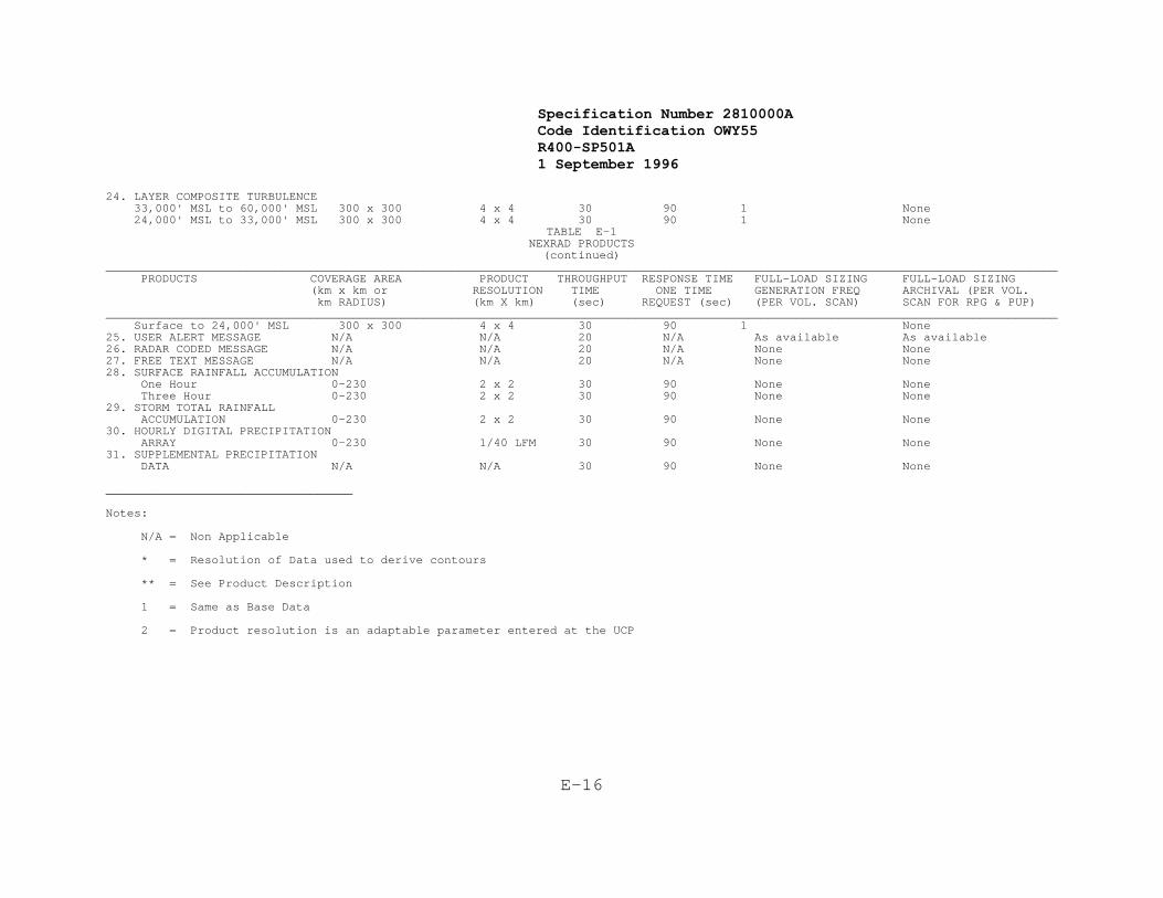
Specification Number 2810000ACode Identification OWY55 R400-SP501A 1 September 1996
E-16
24. LAYER COMPOSITE TURBULENCE 33,000' MSL to 60,000' MSL 300 x 300 4 x 4 30 90 1 None 24,000' MSL to 33,000' MSL 300 x 300 4 x 4 30 90 1 None TABLE E-1
NEXRAD PRODUCTS(continued)
_______________________________________________________________________________________________________________________________________ PRODUCTS COVERAGE AREA PRODUCT THROUGHPUT RESPONSE TIME FULL-LOAD SIZING FULL-LOAD SIZING (km x km or RESOLUTION TIME ONE TIME GENERATION FREQ ARCHIVAL (PER VOL. km RADIUS) (km X km) (sec) REQUEST (sec) (PER VOL. SCAN) SCAN FOR RPG & PUP)_______________________________________________________________________________________________________________________________________ Surface to 24,000' MSL 300 x 300 4 x 4 30 90 1 None25. USER ALERT MESSAGE N/A N/A 20 N/A As available As available 26. RADAR CODED MESSAGE N/A N/A 20 N/A None None27. FREE TEXT MESSAGE N/A N/A 20 N/A None None28. SURFACE RAINFALL ACCUMULATION One Hour 0-230 2 x 2 30 90 None None Three Hour 0-230 2 x 2 30 90 None None29. STORM TOTAL RAINFALL ACCUMULATION 0-230 2 x 2 30 90 None None30. HOURLY DIGITAL PRECIPITATION ARRAY 0-230 1/40 LFM 30 90 None None31. SUPPLEMENTAL PRECIPITATION DATA N/A N/A 30 90 None None
___________________________________
Notes:
N/A = Non Applicable
* = Resolution of Data used to derive contours
** = See Product Description
1 = Same as Base Data
2 = Product resolution is an adaptable parameter entered at the UCP

Specification Number 2810000ACode Identification OWY55 R400-SP501A 1 September 1996
F-1
APPENDIX F
OBSOLETE

Specification Number 2810000ACode Identification OWY55 R400-SP501A 1 September 1996
G-1
APPENDIX GACRONYMS/ABBREVIATIONS
AETC Air Force Air Training and Education Command
AFB Air Force Base
AFI Air Force Instructions
A/D Analog/Digital
AFGL Air Force Geophysics Laboratory
AFGWC Air Force Global Weather Central
AFOS Automation of Field Operations and Services
ANSI American National Standards Institute
ARTCC Air Route Traffic Control Center
ASTM American Standard Testing Methods
ATC Air Traffic Control
ATE Automatic Test Equipment
AWS Air Weather Service
BITE Built In Test Equipment
BWS Base Weather Station
CCB Configuration Control Board
CDP Common Data Processor
CDR Critical Design Review
CDRL Contract Data Requirements List
CI Configuration Item
CMS Configuration Management System
CONUS Continental United States
CPCI Computer Program Configuration Item
CWP Central Weather Processor
CWSU Center Weather Service Unit
APPENDIX GACRONYMS/ABBREVIATIONS
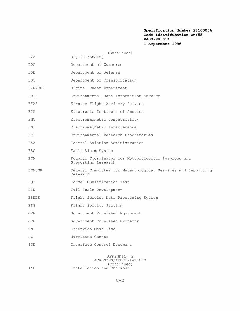
Specification Number 2810000ACode Identification OWY55 R400-SP501A 1 September 1996
G-2
(Continued)D/A Digital/Analog
DOC Department of Commerce
DOD Department of Defense
DOT Department of Transportation
D/RADEX Digital Radar Experiment
EDIS Environmental Data Information Service
EFAS Enroute Flight Advisory Service
EIA Electronic Institute of America
EMC Electromagnetic Compatibility
EMI Electromagnetic Interference
ERL Environmental Research Laboratories
FAA Federal Aviation Administration
FAS Fault Alarm System
FCM Federal Coordinator for Meteorological Services andSupporting Research
FCMSSR Federal Committee for Meteorological Services and SupportingResearch
FQT Formal Qualification Test
FSD Full Scale Development
FSDPS Flight Service Data Processing System
FSS Flight Service Station
GFE Government Furnished Equipment
GFP Government Furnished Property
GMT Greenwich Mean Time
HC Hurricane Center
ICD Interface Control Document
APPENDIX GACRONYMS/ABBREVIATIONS
(Continued)I&C Installation and Checkout

Specification Number 2810000ACode Identification OWY55 R400-SP501A 1 September 1996
G-3
IFR Instrument Flight Rules
IOC Initial Operating Capability
IOTF Interim Operational Test Facility
JDOP Joint Doppler Operational Project
JOR Joint Operational Requirements
JPDP Joint Program Development Plan
JSPO Joint System Program Office
LCC Life Cycle Cost
LLI Long Lead Item
LP Limited Production
LRU Line (Lowest) Replaceable Unit
MAX Maximum
MDT Maximum Downtime
MIE Minimum Interpretive Effort
MIN Minimum
MLOS Microwave Line of Sight
MOC Meteorological Operations Capability
MTBF Mean Time Between Failures
MTBV Mean Time Between Visits
MTTR Mean Time to Repair
NADIN National Airspace Data Interchange Network
NAS National Airspace System
NEDS Naval Environmental Display Station
NEXRAD Next Generation Weather Radar
APPENDIX GACRONYMS/ABBREVIATIONS
(Continued)NHC National Hurricane Center
NMC National Meteorological Center

Specification Number 2810000ACode Identification OWY55 R400-SP501A 1 September 1996
G-4
NOAA National Oceanic and Atmospheric Administration
NOC Naval Oceanography Command
NOCD Naval Oceanography Command Detachment
NPC NEXRAD Program Council
NSSFC National Severe Storms Forecast Center
NSSL National Severe Storms Laboratory
Specification NEXRAD Technical Requirements
NWS National Weather Service
O&M Operations and Maintenance
OJT On Job Training
OMB Office of Management and Budget
OSF Operational Support Facility
PDL Program Design Language
PDR Preliminary Design Review
PRF Pulse Repetition Frequency
PRT Pulse Repetition Time
PUES Principal User External System
PUP Principal User Processing
RAWARC Radar Report and Warning Coordination Circuit
R&D Research and Development
RDA Radar Data Acquisition
RF Radio Frequency
RFC River Forecast Center
APPENDIX GACRONYMS/ABBREVIATIONS
(Continued)
RFI Radio Frequency Interference
RFP Request for Proposal
RGDAC Rain Gage Data Acquisition Computer
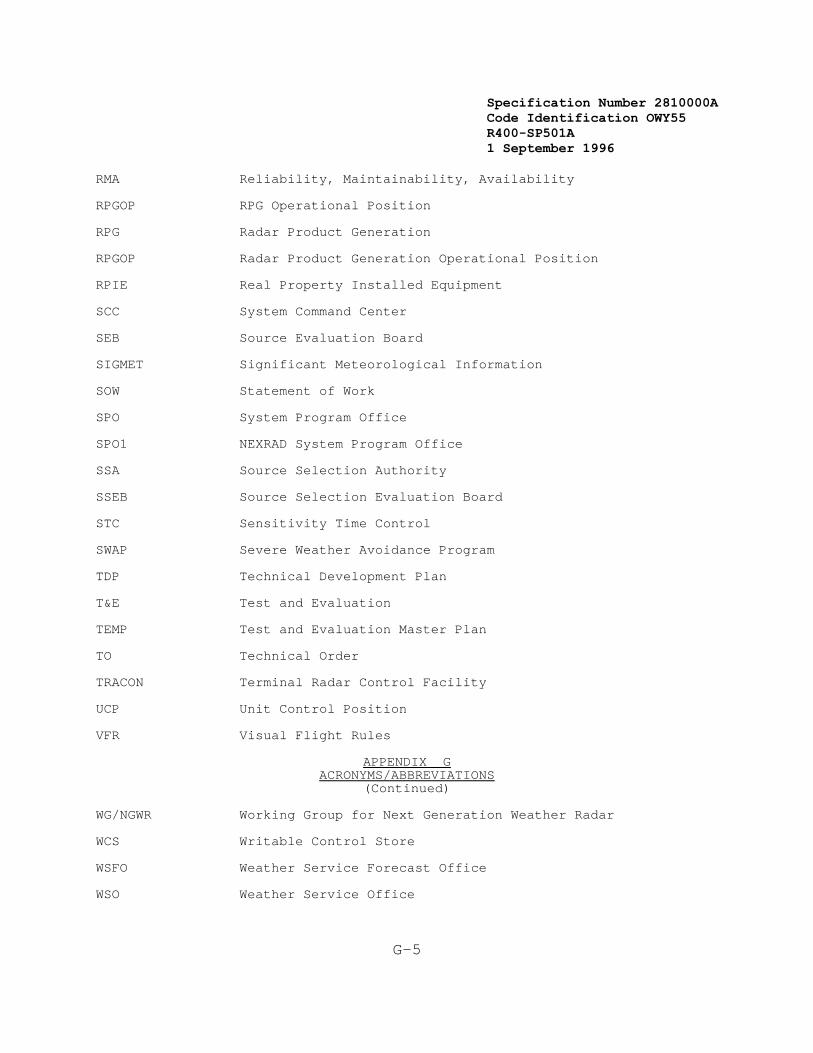
Specification Number 2810000ACode Identification OWY55 R400-SP501A 1 September 1996
G-5
RMA Reliability, Maintainability, Availability
RPGOP RPG Operational Position
RPG Radar Product Generation
RPGOP Radar Product Generation Operational Position
RPIE Real Property Installed Equipment
SCC System Command Center
SEB Source Evaluation Board
SIGMET Significant Meteorological Information
SOW Statement of Work
SPO System Program Office
SPO1 NEXRAD System Program Office
SSA Source Selection Authority
SSEB Source Selection Evaluation Board
STC Sensitivity Time Control
SWAP Severe Weather Avoidance Program
TDP Technical Development Plan
T&E Test and Evaluation
TEMP Test and Evaluation Master Plan
TO Technical Order
TRACON Terminal Radar Control Facility
UCP Unit Control Position
VFR Visual Flight Rules
APPENDIX GACRONYMS/ABBREVIATIONS
(Continued)
WG/NGWR Working Group for Next Generation Weather Radar
WCS Writable Control Store
WSFO Weather Service Forecast Office
WSO Weather Service Office

Specification Number 2810000ACode Identification OWY55 R400-SP501A 1 September 1996
G-6

Specification Number 2810000ACode Identification OWY55 R400-SP501A 1 September 1996
G-7
This Page Intentionally Left Blank

Specification Number 2810000ACode Identification OWY55 R400-SP501A 1 September 1996
H-1
APPENDIX H
ADAPTATION PARAMETERS
The NEXRAD adaptation parameters that have been identified are listed inTable H-1. The list identifies which parameters are applicable to theRDA, RPG, and PUP functional areas. Following Table H-1, the meaningand use of each adaptation parameter are discussed. The list isintended to be illustrative. The contractor shall supply a similar listdetailing all parameters appropriate to the detailed system designchosen. Nominal values and acceptable ranges for each parameter shallbe defined by the contractor subject to Government review and approval.
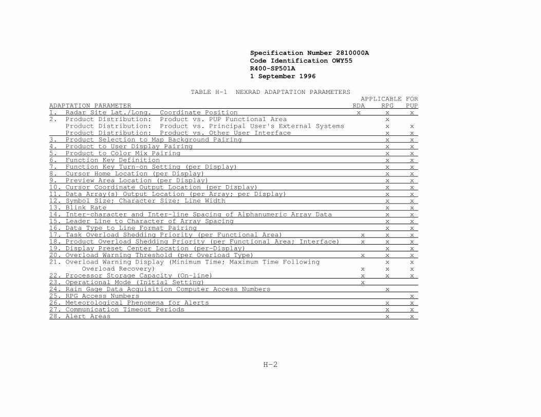
Specification Number 2810000ACode Identification OWY55 R400-SP501A 1 September 1996
H-2
TABLE H-1 NEXRAD ADAPTATION PARAMETERS APPLICABLE FOR
ADAPTATION PARAMETER RDA RPG PUP1. Radar Site Lat./Long. Coordinate Position x x x 2. Product Distribution: Product vs. PUP Functional Area x Product Distribution: Product vs. Principal User's External Systems x x Product Distribution: Product vs. Other User Interface x x 3. Product Selection to Map Background Pairing x x 4. Product to User Display Pairing x x 5. Product to Color Mix Pairing x x 6. Function Key Definition x x 7. Function Key Turn-on Setting (per Display) x x 8. Cursor Home Location (per Display) x x 9. Preview Area Location (per Display) x x 10. Cursor Coordinate Output Location (per Display) x x 11. Data Array(s) Output Location (per Array; per Display) x x 12. Symbol Size; Character Size; Line Width x x 13. Blink Rate x x 14. Inter-character and Inter-line Spacing of Alphanumeric Array Data x x 15. Leader Line to Character of Array Spacing x x 16. Data Type to Line Format Pairing x x 17. Task Overload Shedding Priority (per Functional Area) x x x 18. Product Overload Shedding Priority (per Functional Area; Interface) x x x 19. Display Preset Center Location (per-Display) x x 20. Overload Warning Threshold (per Overload Type) x x x 21. Overload Warning Display (Minimum Time; Maximum Time Following x x Overload Recovery) x x x 22. Processor Storage Capacity (On-line) x x x 23. Operational Mode (Initial Setting) x 24. Rain Gage Data Acquisition Computer Access Numbers x 25. RPG Access Numbers x 26. Meteorological Phenomena for Alerts x x 27. Communication Timeout Periods x x 28. Alert Areas x x

Specification Number 2810000ACode Identification OWY55 R400-SP501A 1 September 1996
H-3
1. Radar Site Latitude/Longitude Coordinate Position:
A geographic position on the NEXRAD System geographic griddefining the radar site location to within a 1/4 km resolution.
2. Product Distribution: Product vs. PUP Functional Area (per RPGinterface)
Product Distribution: Product vs. Principal User ExternalSystems (per RPG interface)
Product Distribution: Product vs. Other User Interface (per RPGinterface)
Tables defining the distribution of NEXRAD products. The Productvs. PUP Functional Area tables will be used by the RPG to controlthe distribution of products to associated and non-associated PUP functional areas. The Product vs. Principal User External Systems tables will be used by a NEXRAD Unit to control the distributionof NEXRAD products from the NEXRAD Unit to a Principal UserExternal System. The Product vs. Other User Interface tableswill be used by the NEXRAD Unit to control product distribution to Other Users.
3. Product Selection to Map Background Pairing
The Product Selection to Map Background Pairing adaptationparameter defines the background map(s) which are to be linked toa product selected for display. The actual display of the mapdata will be dependent upon the operator selection(s) of map typesand the operator selection(s) of map content turn on/turn off.
4. Product to User Display Pairing
The Product to Principal User Display Pairing (per interface) adaptation parameter defines a default turn-on condition for each user display.
5. Product to Color Mix Pairing (per PUP)
The Product to Color Mix Pairing adaptation parameter defines a turn-on color selection for the presentation of each data item ofeach product.
6. Function Key Definition
The Function Key Definition adaptation parameter defines that setof functions performed automatically when a specific function keyis selected (activated). Function key examples are productselection, product content turn on/turn off, map selections, mapcontent turn on/turn off, cursor home, magnification selection,test pattern selection/deselection, off-center, preset center,resolution selection, accept queued output message, alarmacknowledge, and enter.
7. Function Key Turn on Setting (per Display)

Specification Number 2810000ACode Identification OWY55 R400-SP501A 1 September 1996
H-4
The Function Key Turn on setting adaptation parameter defines theinitial setting for each Function Key for use during systeminitialization.
8. Cursor Home Location (per Display)
The Cursor Home Location adaptation parameter defines the displaylocation at which the cursor symbol shall be displayed.
9. Preview Area Location (per Display)
The Preview Area Location adaptation parameter defines the displaylocation at which the first alphanumeric character will appear onthe display when an input message is entered.
10. Cursor Coordinate Output Location (per Display)
The Cursor Coordinate Output Location adaptation parameter definesthe display location at which the first character of the cursorcoordinate output message will appear on the display when a cursorposition control function selection key is activated.
11. Data Array(s) Output Location (per Array; per Display)
The Data Array Output Location adaptation parameters define thesize of each alphanumeric data array (number of characters perline, and number of lines) and the display location of the topleft character position of each data array.
12. Symbol Size; Character Size; Line Width
The Symbol Size, Character Size, and Line Width adaptationparameters define the alphanumeric and special symbol characterfont and size in pixels for each character, and the pixels perline for line width.
13. Blink Rate
The Blink Rate adaptation parameter defines the number of times adata item is to be turned on/off in a time period, and the numberof display refresh cycles to be used for both the on and the offcondition.
14. Inter-character and inter-line spacing of alphanumeric array data
The Inter-character and inter-line spacing of array dataadaptation parameter shall define the number of pixels to be usedas spacing between adjacent characters on a line, and the numberof pixels to be used as spacing between adjacent lines ofcharacters.
15. Leader Line to Character or Array Spacing
The Leader Line to Character or Array Spacing adaptation parameterdefines the number of pixels between the end of a line and thecenter of a character or the center of a character in one of the
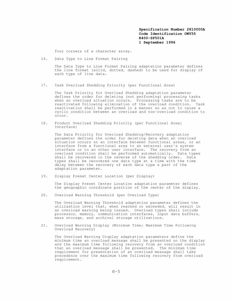
Specification Number 2810000ACode Identification OWY55 R400-SP501A 1 September 1996
H-5
four corners of a character array.
16. Data Type to Line Format Pairing
The Data Type to Line Format Pairing adaptation parameter definesthe line format (solid, dotted, dashed) to be used for display ofeach type of line data.
17. Task Overload Shedding Priority (per Functional Area)
The Task Priority for Overload Shedding adaptation parameterdefines the order for deleting (not performing) processing taskswhen an overload situation occurs. Processing tasks are to bereactivated following elimination of the overload condition. Taskreactivation shall be performed in a manner so as not to cause acyclic condition between an overload and non-overload condition tooccur.
18. Product Overload Shedding Priority (per Functional Area;Interface)
The Data Priority for Overload Shedding/Recovery adaptationparameter defines the order for deleting data when an overloadsituation occurs on an interface between functional areas, or aninterface from a functional area to an external user's systeminterface or to an other user interface. The recovery from anoverload condition shall be performed automatically. Data typesshall be recovered in the reverse of the shedding order. Datatypes shall be recovered one data type at a time with the timedelay between the recovery of each data type a part of theadaptation parameter.
19. Display Preset Center Location (per Display)
The Display Preset Center Location adaptation parameter definesthe geographic coordinate position of the center of the display.
20. Overload Warning Threshold (per Overload Type)
The Overload Warning Threshold adaptation parameter defines theutilization level that, when reached or exceeded, will result inan overload warning being issued. Overload types shall includeprocessor, memory, communication interfaces, input data buffers,mass storage, and archival storage utilizations.
21. Overload Warning Display (Minimum Time; Maximum Time FollowingOverload Recovery)
The Overload Warning Display adaptation parameters define theminimum time an overload message shall be presented on the displayand the maximum time following recovery from an overload conditionthat an overload message shall be presented. The minimum timerequirement for presentation of an overload message shall takeprecedence over the maximum time following recovery from overloadrequirement.

Specification Number 2810000ACode Identification OWY55 R400-SP501A 1 September 1996
H-6
22. Processor Storage Capacity (On-line)
The Processor Storage Capacity adaptation parameter defines theamount of on-line memory available for the operational system.
23. Operational Mode (Initial Setting)
The Operational Mode adaptation parameter defines the radaroperational mode to be used following system initialization.
24. Rain Gage Data Acquisition Computer Access Numbers
The Rain Gage Data Acquisition Computer Access Numbers adaptationparameters define the telephone numbers for each rain gagecomputer.
25. RPG Access Numbers
The RPG Access Numbers adaptation parameters define the telephonenumbers of each RPG for the automatic dial-in for NEXRAD products.
26. Meteorological Phenomena for Alerts
The Meteorological Phenomena for Alerts will specify thresholdsfor all alert categories. Each threshold criterion will contain aset of specific parameter values or phenomenon conditions. Thisset of adaptable thresholds will be maintained at each RPG.
27. Communication Timeout Periods
The Communication Timeout Periods adaptation parameters define thetimeout periods for the five "timers" identified in the ICD. Specifically, these are Status, Acknowledgement, Busy, Idle, andInterframe.

Specification Number 2810000ACode Identification OWY55 R400-SP501A 1 September 1996
H-7
28. Alert Areas
The Alert Area adaptation parameter allows the PUP or RPGOPoperator to define up to two Alert Areas. There is one set ofAlert Areas per PUP or RPG Operational Position. Within thedefined Alert Area(s) the PUP or RPGOP will be capable ofspecifying conditions which will cause an alert.
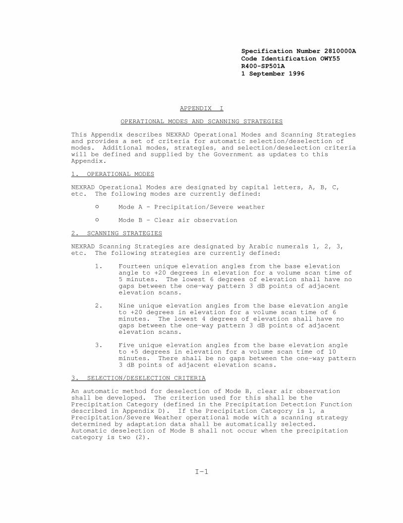
Specification Number 2810000ACode Identification OWY55 R400-SP501A 1 September 1996
I-1
APPENDIX I
OPERATIONAL MODES AND SCANNING STRATEGIES
This Appendix describes NEXRAD Operational Modes and Scanning Strategiesand provides a set of criteria for automatic selection/deselection ofmodes. Additional modes, strategies, and selection/deselection criteriawill be defined and supplied by the Government as updates to thisAppendix.
1. OPERATIONAL MODES
NEXRAD Operational Modes are designated by capital letters, A, B, C,etc. The following modes are currently defined:
" Mode A - Precipitation/Severe weather
" Mode B - Clear air observation
2. SCANNING STRATEGIES
NEXRAD Scanning Strategies are designated by Arabic numerals 1, 2, 3,etc. The following strategies are currently defined:
1. Fourteen unique elevation angles from the base elevationangle to +20 degrees in elevation for a volume scan time of5 minutes. The lowest 6 degrees of elevation shall have nogaps between the one-way pattern 3 dB points of adjacentelevation scans.
2. Nine unique elevation angles from the base elevation angleto +20 degrees in elevation for a volume scan time of 6minutes. The lowest 4 degrees of elevation shall have nogaps between the one-way pattern 3 dB points of adjacentelevation scans.
3. Five unique elevation angles from the base elevation angleto +5 degrees in elevation for a volume scan time of 10minutes. There shall be no gaps between the one-way pattern3 dB points of adjacent elevation scans.
3. SELECTION/DESELECTION CRITERIA
An automatic method for deselection of Mode B, clear air observationshall be developed. The criterion used for this shall be thePrecipitation Category (defined in the Precipitation Detection Functiondescribed in Appendix D). If the Precipitation Category is 1, aPrecipitation/Severe Weather operational mode with a scanning strategy determined by adaptation data shall be automatically selected. Automatic deselection of Mode B shall not occur when the precipitationcategory is two (2).

Specification Number 2810000ACode Identification OWY55 R400-SP501A 1 September 1996
I-2
This Page Intentionally Left Blank
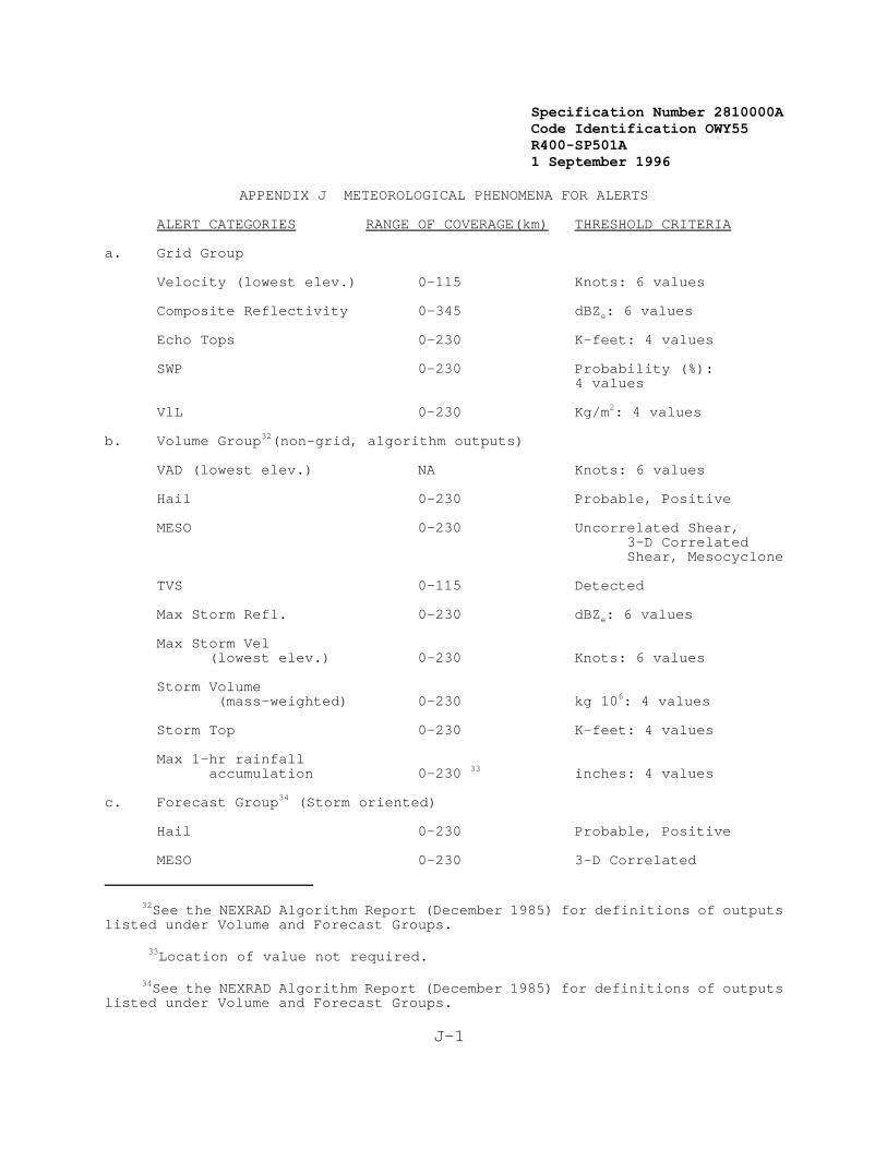
Specification Number 2810000ACode Identification OWY55 R400-SP501A 1 September 1996
32See the NEXRAD Algorithm Report (December 1985) for definitions of outputslisted under Volume and Forecast Groups.
33Location of value not required.
34See the NEXRAD Algorithm Report (December 1985) for definitions of outputslisted under Volume and Forecast Groups.
J-1
APPENDIX J METEOROLOGICAL PHENOMENA FOR ALERTS
ALERT CATEGORIES RANGE OF COVERAGE(km) THRESHOLD CRITERIA
a. Grid Group
Velocity (lowest elev.) 0-115 Knots: 6 values
Composite Reflectivity 0-345 dBZe: 6 values
Echo Tops 0-230 K-feet: 4 values
SWP 0-230 Probability (%):4 values
VlL 0-230 Kg/m2: 4 values
b. Volume Group32(non-grid, algorithm outputs)
VAD (lowest elev.) NA Knots: 6 values
Hail 0-230 Probable, Positive
MESO 0-230 Uncorrelated Shear,3-D CorrelatedShear, Mesocyclone
TVS 0-115 Detected
Max Storm Refl. 0-230 dBZe: 6 values
Max Storm Vel(lowest elev.) 0-230 Knots: 6 values
Storm Volume (mass-weighted) 0-230 kg 106: 4 values
Storm Top 0-230 K-feet: 4 values
Max 1-hr rainfallaccumulation 0-230 33 inches: 4 values
c. Forecast Group34 (Storm oriented)
Hail 0-230 Probable, Positive
MESO 0-230 3-D Correlated
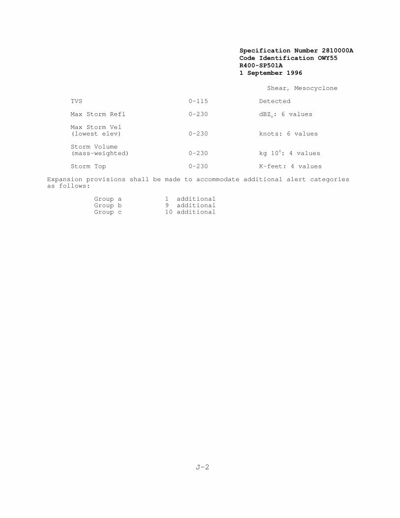
Specification Number 2810000ACode Identification OWY55 R400-SP501A 1 September 1996
J-2
Shear, Mesocyclone
TVS 0-115 Detected
Max Storm Refl 0-230 dBZe: 6 values
Max Storm Vel(lowest elev) 0-230 knots: 6 values
Storm Volume(mass-weighted) 0-230 kg 106: 4 values
Storm Top 0-230 K-feet: 4 values
Expansion provisions shall be made to accommodate additional alert categoriesas follows:
Group a 1 additionalGroup b 9 additionalGroup c 10 additional

Specification Number 2810000ACode Identification OWY55 R400-SP501A 1 September 1996
J-3
This Page Intentionally Left Blank
Specification Number 2810000ACode Identification OWY55 R400-SP501A 1 September 1996
K-1
APPENDIX KRADAR CODED MESSAGE CODE
The Radar Coded Message, as described in Item 26, Appendix E, NEXRADProducts, shall be composed of three parts, preceded by a communicationsheader. Part A, Reflectivity, and Part B, VAD Winds, shall be encodedautomatically. Part C, Remarks, shall be encoded automatically or at thePUP as specified in that part. In the groups below, capital lettersrepresent the fixed part of the group, and small letters representvariables. The message shall be encoded as follows:
Header. The header is encoded as follows:
ccc The communications node (PUP site identifier).
ROBEE The product category for edited radar coded message. or ROBUU The product category for unedited radar coded message.
sidd(C/R) Four letter RDA site identifier.
(Example: cccROBEE sidd (C/R))
Part A: Reflectivity
Part A of the Radar Coded message (RCM) contains an intermediate graphicproduct and a tabular listing of alphanumerics. Data in the Radar CodedMessage are located with respect to a polar stereographic grid. Thelocal grid at each antenna site is designed to be a subject of theNational Radar Grid so that data may be readily composited.
The National Radar Grid has a resolution of 1/4 LFM (Limited Fine Mesh Model) which is 47.625 km at 60 degrees north latitude. The verticalaxis of the grid is parallel to the 105 degree west longitude meridian.
At each site, a local grid is chosen having 25 rows and 25 columns, withthe antenna site located within the central box. The 25 rows and columnsof the grid are assigned letters A through Y, so that the box containingthe antenna site is always box MM. Box AA is at the upper left. Asshown in Figure K-1, each box is further subdivided to form an overall1/16 LFM grid.
The graphic product contains reflectivity data for the 1/16 LFM grid overthe radar area of coverage out to 460 km. The reflectivity intensityvalue for each grid box is determined by assigning the maximum value ofall Composite Reflectivity boxes whose centers are contained within the1/16 LFM grid square.
The RCM is based on the 16 level, 4 km x 4 km Composite Reflectivityproduct but contains only 9 data level categories; 6 for data and 1 formissing or below threshold data within 230 km and 2 for data beyond 230km. For data beyond 230 km, a separate threshold is provided for which:a) all data above that threshold are labeled as level 8, and b) all databelow that threshold are labeled as level 9. The intermediate graphicproduct is displayed at the RPGOP or PUP for editing by changing ordeleting data within outlined areas by using the cursor control device.
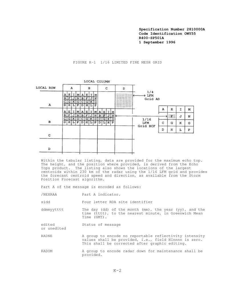
Specification Number 2810000ACode Identification OWY55 R400-SP501A 1 September 1996
K-2
FIGURE K-1 1/16 LIMITED FINE MESH GRID
Within the tabular listing, data are provided for the maximum echo top. The height, and the position where provided, is derived from the EchoTops product. The listing also shows the locations of the largestcentroids within 230 km of the radar using the 1/16 LFM grid and providesthe forecast centroid speed and direction, as available from the StormPosition Forecast algorithm.
Part A of the message is encoded as follows:
/NEXRAA Part A indicator.
sidd Four letter RDA site identifier
ddmmyytttt The day (dd) of the month (mm), the year (yy), and the
time (tttt), to the nearest minute, in Greenwich MeanTime (GMT).
edited Status of messageor unedited
RADNE A group to encode no reportable reflectivity intensityvalues shall be provided, i.e., field NInnnn is zero. This shall be corrected after graphic editing.
RADOM A group to encode radar down for maintenance shall be
provided.
Specification Number 2810000ACode Identification OWY55 R400-SP501A 1 September 1996
K-3
/MDnnnn A group of six characters to encode operational modeshall be provided. See Appendix I. Choices are PCPNand CLAR. (Example: /MDPCPN)
/SCnnnn A group of six characters to encode scan strategy shallbe provided. See Appendix I. Choices are 1405 (14scans in 5 minutes), 0906, 0510, etc. (Example: /SC1405)
/NInnnn: The total number (nnnn) of intensities (NI) reported in the following field (gggi) shall be encoded. Thisgroup shall be corrected after editing, if editing isperformed. (Example: /NIO144)
gggi Reflectivity intensity shall be mapped onto the 1/16LFM grid (ggg). Encode locations and intensities by aseries of groups made up of three letters (1/16 LFM)followed by the maximum intensity of the designatedgrid box. The three letters (in order) shall be row,column, and sub-grid. The numbers following, representintensities in succeeding sub-grid boxes in that row. That is, encode each 1/16 LFM grid box from west toeast, starting with the northern-most row with data,followed by the next southern row, etc. In theinterest of compacting the message, successiveintensities of different or similar values may belisted after a single location as long as theintensities are continuous. When succeeding grid boxescontain the same intensity value, the number ofsucceeding boxes with the same value may be designatedby a letter of the alphabet. That is, if 4 succeeding1/16 LFM grid boxes (a total of five boxes) are atlevel 2, they could be coded as GGG2D. The "2D" mayalso be followed by different intensity values. Location/intensity groups shall be separated by acomma. (Example: ABF112D331,BCA1211)
/MThhh:ggg The location and height (MSL) of the maximum echo top(MT) within 230km radius of the radar shall be encodedusing the three letter grid designator (ggg) andassigning the height coinciding with echo top productin hundreds of feet (hhh). (Example: /MT320:NLB)
/NCENnn: The total number (nn) of centroids (NCEN) reported inthis portion of the message shall be encoded. Thisnumber shall correspond to the corrected centroidsbelow. (Example: /NCEN04:)
Cnnggg dddfff The centroid (C) number (nn), location (grid box)(ggg), direction from which it is moving (in onedegree increments) (ddd), and its speed (fff) in knots,shall be encoded. Successive groups shall be separatedby commas. If, during editing, data are deleted in agrid box that contains a centroid, this group shall becorrected by deleting this centroid. (Example: C03QMB240012)
Specification Number 2810000ACode Identification OWY55 R400-SP501A 1 September 1996
K-4
/ENDAA(C/R) A group to indicate the end of Part A.
The following is a summary example of the components of Part A. /NEXRAA sidd 2812881330 Edited (C/R)
/MDnnnn /SCnnnn /NInnnn:
gggiii ... i,gggiii...i
/MThhh:ggg
/NCENnn: Cnnggg dddfff,Cnnggg dddfff
/ENDAA (C/R)
Part B: VAD Winds
Part B of the RCM contains a single profile of the horizontal windinformation derived from the output of the VAD algorithm. Part B of themessage is encoded as follows:
/NEXRBB Part B indicator.
sidd Four letter RDA site identifier.
ddmmyytttt The day (dd) of the month (mm), the year (yy), and the time
(tttt), to the nearest minute, in GMT.
VADNA The optional entry VADNA shall be encoded for instances whenno VAD wind data are available for the last 15 minutes, ifappropriate.
hhhcdddfff Coded heights (hhh) in hundreds of feet MSL; confidence (c)
level, using RMS for the coded height; wind direction (ddd)and wind speed (fff), in knots, shall coincide with thosederived from the VAD Winds product. The confidence levelshall be encoded as a single letter in accordance with thefollowing:
A = RMS of 1 m s-1; B = RMS of 2 m s-1; C = RMS of 3 m s-1; D = RMS of 4 m s-1; E = RMS of 5 m s-1; F = RMS of 6 m s-1; G = RMS of greater than or equal to 7 m s-1.
Wind direction and speed, as output from the VAD algorithm, shall bereported at up to 19 heights, in feet MSL. Default heights are:
1,000 6,000 12,000 25,000 2,000 7,000 14,000 30,000 3,000 8,000 16,000 35,000 4,000 9,000 18,000 50,000 5,000 10,000 20,000 (Example: 080C240060)

Specification Number 2810000ACode Identification OWY55 R400-SP501A 1 September 1996
K-5
/ENDBB (C/R) End of Part B indicator.
The following is a summary example of the components of Part B.
/NEXRBB sidd 2812881330 (C/R)
hhhcdddfff,hhhcdddfff,hhhcdddfff
/ENDBB (C/R)
Part C: Remarks
Part C of the Radar Coded Message contains remarks in an alphanumericformat. Automatically generated remarks provide information on thelocations of tornadic vortex signatures, mesocyclones, centroids, stormtops, and hail indices. The automated portion of Part C is encoded asfollows:
/NEXRCC Part C indicator.
sidd Four letter RDA site identifier.
ddmmyytttt The day (dd) of the month (mm), the year (yy), and the time (tttt), to the nearest minute, in GMT.
/NTVSnn: The total number (nn) of tornadic vortex signatures (NTVS)detected by the TVS algorithm and reported in Part C shall beencoded. (Example: /NTVS03:).
TVSnnggg The location (ggg) and number identifier (nn) of each
tornadic vortex signature (TVS) shall be encoded using thethree-letter grid box designator. (Example: TVS02NLB).
/NMESnn: The total number (nn) of mesocyclones and areas of couplet
(NMES) detected by the Mesocyclone Detection algorithm andreported in Part C shall be encoded. (Example: /NMES05:).
Mnnggg The location (ggg) and number identifier (nn) of each mesocyclone or area of couplet (M) shall be encoded using thethree-letter grid box designator. (Example: M03JLC).
/NCENnn: The total number (nn) of centroids (NCEN) reported in Part C
shall be encoded. (Example: /NCEN08:)
Cnnggg ShhhHi The height (hhh) in hundreds of feet (MSL), of thestorm top (S), as derived from the Storm Structurealgorithm, for each centroid (C) identified in Part Ato include location (ggg) shall be encoded. Thecentroid identifier number (nn) is the same as given inPart A. The hail (H) index (i), as provided by theHail algorithm, is also given as one of the fourfollowing data levels:
N - no hail; P - possible or probable hail; H - hail; U - unknown.

Specification Number 2810000ACode Identification OWY55 R400-SP501A 1 September 1996
K-6
(Example: C04QQD S440HP).
In addition to the automatically generated remarks, Part C provides foroptional manual entries. A template is provided containing the fixedpart of the groups listed below. The only groups to be sent are those towhich data are added. It should be noted that the absence of a remarkdoes not imply that the phenomenon does not exist.
/PCTRyyyy,aaa:gg Precipitation type and intensity trend. Precipitationtype (yyyy) may be coded for a representative area ofthe display. The type is variable and up to fivecharacters in length. The intensity trend (aaa) isalso variable in length and up to three characters inlength. The location (gg) is reported using the twoletter identifier for the 1/4 LFM grid.
For convective echo systems, the characteristic type of precipitation isdefined as that type associated with the maximum observed intensity. Fornon-convective echo systems, the type of precipitation is defined as thattype predominant in horizontal extent. If precipitation is reaching thesurface, report that type.
Precipitation Symbol Rain R Rain Shower RW Freezing Rain ZR Freezing Rainshower ZRW Snow S Snow Shower SW Drizzle L Freezing Drizzle ZL Ice Pellet IP Ice Pellet Shower IPW
Designated areas believed to be associated with thunderstorms may use thesymbol T preceding the precipitation symbol.
Evaluate the intensity trend in terms of the net change in thecharacteristic intensity during a period of 1 hour for lines and areasand 15 minutes for cells.
Report the intensity trend as increasing (+) or decreasing (-), if,during the period, the net change in characteristic intensity (dBZe)changes from one intensity level to another.
If the net change in the characteristic intensity during the period doesnot change categories, report the intensity trend as NC (no change).
Report echo systems as NEW (new development) if they originated duringthe period specified above. Areas or lines that develop from a cell orcells during the hour preceding the report shall be reported as NEW.
For a mixed system, consisting of a liquid characteristic type ofprecipitation and a frozen secondary type, report the intensity trend of
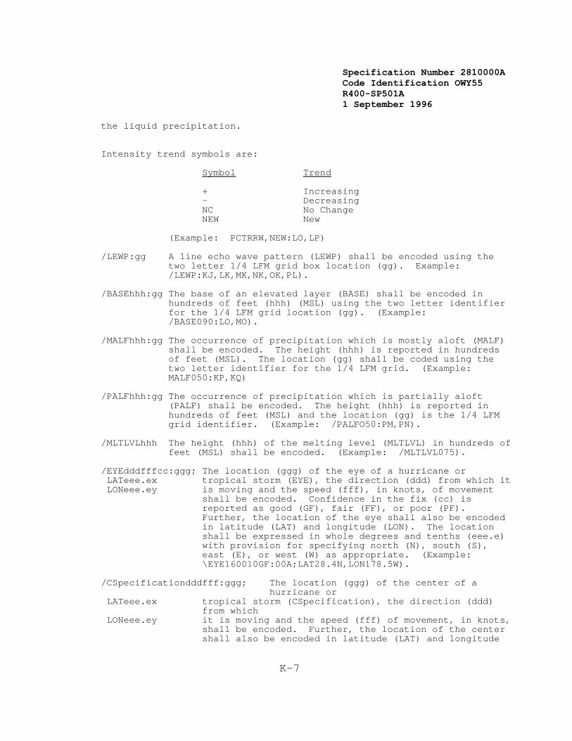
Specification Number 2810000ACode Identification OWY55 R400-SP501A 1 September 1996
K-7
the liquid precipitation.
Intensity trend symbols are: Symbol Trend + Increasing - Decreasing NC No Change NEW New (Example: PCTRRW,NEW:LO,LP)
/LEWP:gg A line echo wave pattern (LEWP) shall be encoded using thetwo letter 1/4 LFM grid box location (gg). Example: /LEWP:KJ,LK,MK,NK,OK,PL).
/BASEhhh:gg The base of an elevated layer (BASE) shall be encoded in
hundreds of feet (hhh) (MSL) using the two letter identifierfor the 1/4 LFM grid location (gg). (Example: /BASE090:LO,MO).
/MALFhhh:gg The occurrence of precipitation which is mostly aloft (MALF)
shall be encoded. The height (hhh) is reported in hundredsof feet (MSL). The location (gg) shall be coded using thetwo letter identifier for the 1/4 LFM grid. (Example:MALF050:KP,KQ)
/PALFhhh:gg The occurrence of precipitation which is partially aloft
(PALF) shall be encoded. The height (hhh) is reported inhundreds of feet (MSL) and the location (gg) is the 1/4 LFMgrid identifier. (Example: /PALFO50:PM,PN).
/MLTLVLhhh The height (hhh) of the melting level (MLTLVL) in hundreds offeet (MSL) shall be encoded. (Example: /MLTLVL075).
/EYEdddfffcc:ggg; The location (ggg) of the eye of a hurricane or LATeee.ex tropical storm (EYE), the direction (ddd) from which it
LONeee.ey is moving and the speed (fff), in knots, of movementshall be encoded. Confidence in the fix (cc) isreported as good (GF), fair (FF), or poor (PF). Further, the location of the eye shall also be encodedin latitude (LAT) and longitude (LON). The locationshall be expressed in whole degrees and tenths (eee.e)with provision for specifying north (N), south (S),east (E), or west (W) as appropriate. (Example:\EYE160010GF:00A;LAT28.4N,LON178.5W).
/CSpecificationdddfff:ggg; The location (ggg) of the center of ahurricane or
LATeee.ex tropical storm (CSpecification), the direction (ddd)from which
LONeee.ey it is moving and the speed (fff) of movement, in knots,shall be encoded. Further, the location of the centershall also be encoded in latitude (LAT) and longitude
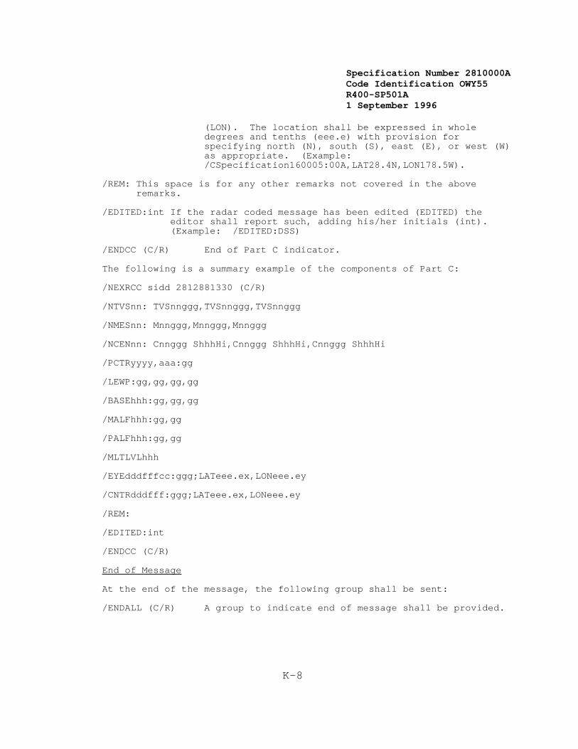
Specification Number 2810000ACode Identification OWY55 R400-SP501A 1 September 1996
K-8
(LON). The location shall be expressed in wholedegrees and tenths (eee.e) with provision forspecifying north (N), south (S), east (E), or west (W)as appropriate. (Example:/CSpecification160005:00A,LAT28.4N,LON178.5W).
/REM: This space is for any other remarks not covered in the aboveremarks.
/EDITED:int If the radar coded message has been edited (EDITED) the
editor shall report such, adding his/her initials (int). (Example: /EDITED:DSS)
/ENDCC (C/R) End of Part C indicator.
The following is a summary example of the components of Part C:
/NEXRCC sidd 2812881330 (C/R)
/NTVSnn: TVSnnggg,TVSnnggg,TVSnnggg
/NMESnn: Mnnggg,Mnnggg,Mnnggg
/NCENnn: Cnnggg ShhhHi,Cnnggg ShhhHi,Cnnggg ShhhHi
/PCTRyyyy,aaa:gg
/LEWP:gg,gg,gg,gg /BASEhhh:gg,gg,gg /MALFhhh:gg,gg /PALFhhh:gg,gg /MLTLVLhhh
/EYEdddfffcc:ggg;LATeee.ex,LONeee.ey
/CNTRdddfff:ggg;LATeee.ex,LONeee.ey
/REM:
/EDITED:int
/ENDCC (C/R)
End of Message
At the end of the message, the following group shall be sent:
/ENDALL (C/R) A group to indicate end of message shall be provided.
Specification Number 2810000ACode Identification OWY55 R400-SP501A 1 September 1996
L-1
Appendix L
This Appendix Intentionally Left Blank.

Specification Number 2810000ACode Identification OWY55 R400-SP501A 1 September 1996
L-2
This Page Intentionally Left Blank

Specification Number 2810000ACode Identification OWY55 R400-SP501A 1 September 1996
M-1
APPENDIX MNEXRAD ACCESS ROADS
1. DESCRIPTION
This Appendix contains the performance specification for access roads. Access roads shall be provided to each radar and microwave repeater site.
2. PERFORMANCE SPECIFICATION
An all-weather access road suitable for use by 2-wheel drive sedans shallbe provided. Minimum road width shall be 10 feet shoulder to shoulder,with the roadway to be crowned or cross-sloped to drain. Maximum gradeshall be 12 percent, except that grade may be exceeded for shortdistances (up to 100 feet) at the Government's option. Passing turnoutsshall be provided at a maximum spacing of 600 feet.
Adequate cross drainage culverts for a 10 year storm shall be provided inwater courses and low spots to prevent ponding. The subgrade shall beadequately compacted, so that the combined subgrade and surface coursewill carry 2-wheel sedan traffic during wet weather without rutting orpumping. If the native material is a fat clay, peat, organic, or otherunsuitable material, and is inadequate to satisfy the precedingrequirement, the roadway area shall be excavated and backfilled withgranular material, or overlain with granular material, to a depthsufficient to carry the 2-wheel sedan traffic during wet weather.
A 4-inch thick compacted crusher-run surface course shall be provided,except that this requirement may be altered or waived at the Government'soption. Prior to site commissioning, the roadway surface shall be bladedand compacted to reestablish the crown or cross-slope, and to remove anypotholes or wash-boarding.
If operational facilities at an airport, including apron, runway, andtaxiways, are paved, any roadway within 300 feet shall also be surfacedwith a double bituminous surface treatment on top of the surface course.

Specification Number 2810000ACode Identification OWY55 R400-SP501A 1 September 1996
M-2
This Page Intentionally Left Blank