nico jurtz*, matthias kraume and gregor d. wehinger
TRANSCRIPT
Rev Chem Eng 2019; 35(2): 139–190
Nico Jurtz*, Matthias Kraume and Gregor D. Wehinger
Advances in fixed-bed reactor modeling using particle-resolved computational fluid dynamics (CFD)https://doi.org/10.1515/revce-2017-0059Received July 14, 2017; accepted November 17, 2017; previously published online February 2, 2018
Abstract: In 2006, Dixon et al. published the compre-hensive review article entitled “Packed tubular reactor modeling and catalyst design using computational fluid dynamics.” More than one decade later, many research-ers have contributed to novel insights, as well as a deeper understanding of the topic. Likewise, complexity has grown and new issues have arisen, for example, by cou-pling microkinetics with computational fluid dynamics (CFD). In this review article, the latest advances are sum-marized in the field of modeling fixed-bed reactors with particle-resolved CFD, i.e. a geometric resolution of every pellet in the bed. The current challenges of the detailed modeling are described, i.e. packing generation, meshing, and solving with an emphasis on coupling microkinetics with CFD. Applications of this detailed approach are dis-cussed, i.e. fluid dynamics and pressure drop, dispersion, heat and mass transfer, as well as heterogeneous catalytic systems. Finally, conclusions and future prospects are presented.
Keywords: CFD; fixed-bed reactor; fluid dynamics; heat transfer; surface chemistry.
AbbreviationsADPF axially dispersed plug flowBCC body-centered cubicBET Brunauer-Emmett-TellerCAD computer aided designCFD computational fluid dynamicsCPOX catalytic partial oxidation
CT computer tomographyDEM discrete element methodDFT density functional theoryDNS direct numerial simulationDRM dry reforming of methaneFCC face-centered cubicFHS front heat shieldLES Large eddy simulationLHHW Langmuir-Hinshelwood-Hougon-WatsonPIV particle-image velocimetryRANS Reynolds-averaged Navier-StokesRTD residence-time distributionSFR stagnation-flow reactorSRM steam reforming of methaneSST shear-stress transportS2S surface-to-surfaceTST transition-state theory
1 IntroductionFixed-bed reactors are a widely used reactor type in the chemical and process industry. Among other applica-tions, they play a key role for heterogeneous catalysis, e.g. steam and dry reforming of methane, the oxidative coupling of methane to ethylene, or the Sabatier process. Due to the strong endothermic (or exothermic) character of many kinds of surface reactions, heat needs to be effec-tively transferred into (or out of) the system. This leads to reactors with a small tube diameter. The particle size is restricted by several constraints like low pressure drop, high gas through-put, and high specific catalytic surface area. These restrictions lead to a reactor arrangement with a small tube-to-particle diameter ratio (D/dp = N).
For fixed beds with a small N, conventional approaches like pseudo-homogeneous or heterogeneous models are not well suited, as they do not take into account local flow effects having a dramatic influence on fluid dynamics, as well as heat and mass transfer. For that reason, starting in the late 1990s, a considerable growing number of research-ers developed methods to investigate the physical phe-nomena that take place in fixed-bed reactors by applying computational fluid dynamics (CFD) for three-dimensional
*Corresponding author: Nico Jurtz, Chemical and Process Engineering, Technical University of Berlin, Fraunhoferstr. 33-36, 10587 Berlin, Germany, e-mail: [email protected] Kraume: Chemical and Process Engineering, Technical University of Berlin, Fraunhoferstr. 33-36, 10587 Berlin, GermanyGregor D. Wehinger: Chemical and Electrochemical Process Engineering, Clausthal University of Technology, Leibnizstr. 17, 38678 Clausthal-Zellerfeld, Germany

140 N. Jurtz et al.: Advances in fixed-bed reactor modeling using CFD
(3D) particle-resolved simulations. This modeling approach takes into account the actual geometric structure in beds consisting of pellets. This means that the trans-port of momentum, heat, and species mass is resolved in the interstitial region of the pellets. Also, it is possible to resolve transport of heat and species mass in the interior of the pellets (intraparticle transport). As can be seen in Figure 1, the porous media model uses averaged values for the bed morphology. There is no clear distinction between the phases. Particle-resolved CFD simulations reconstruct the actual pellet shapes, which influences transport phe-nomena on a local basis. The corresponding porosity of the two approaches is illustrated in Figure 1C.
In 2006, Dixon et al. summarized the development of particle-resolved CFD simulations, which started in the mid-1990s. Many important aspects were covered, such as packing generation, meshing, and some applications of fluid dynamic problems including heat transfer, mass transfer, and chemical reactions. Due to the limited com-putational hardware at that time, the investigations were restricted to either periodic segments of a regular arranged packing or a small amount of particles (<50) forming a random fixed bed.
In the last 10 years, computer hardware has become much faster and more affordable. Furthermore, modern computer architecture makes it possible to connect multiple
processor nodes to one high performance cluster (HPC). Together with the possibility of process parallelization, this leads to an intensified attraction using CFD in the field of chemical and process engineering in the last years, both in industry and academia. A growing part of this increased application covers numerical investigations of fixed-bed reactors. From the beginning, in the mid-1990s, almost 500 publications can be found on Scopus (2017) by searching for CFD and fixed bed or packed bed, see Figure 2, although not all of these publications use the particle-resolved model. On the one hand, this is a true indicator that there are still open questions that need to be answered. On the other hand, it shows that CFD has been developed to a useful tool that helps to gain in-depth insights of complex reactor devices.
This work summarizes the advances that have been made within the last decade in the field of fixed-bed reactor modeling. Earlier development was reviewed com-prehensively by Dixon et al. (2006). We show and discuss recent results, new and improved modeling approaches, and limitations that still exist. Furthermore, some current best practices are derived. The next section will discuss challenges during a typical workflow that needs to be tackled for a successful CFD simulation. The third section is addressed to the discussion of recent applications of particle-resolved CFD simulations. Finally, conclusions are drawn and future prospects are presented.
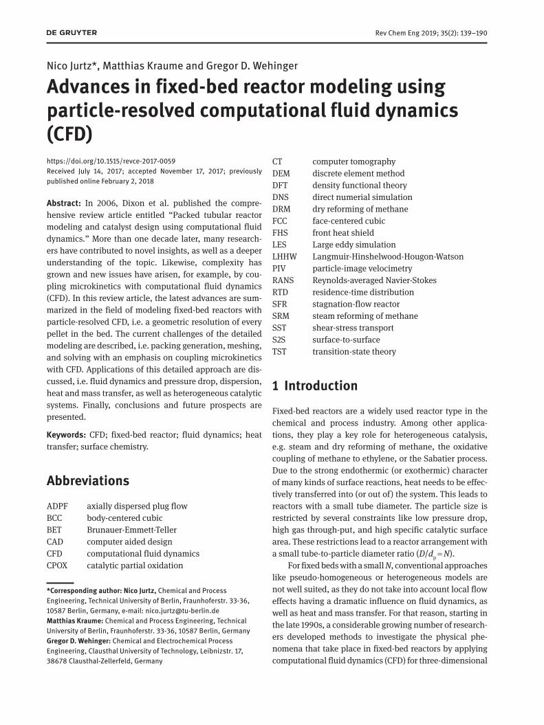
2 General workflow and challengesThe general workflow for particle-resolved CFD simula-tions of fixed-bed reactors is presented in Figure 3 includ-ing the corresponding chapters of this review. The first step is the generation of a representative geometry, which can be based on a scanned original sample, a regular
Figure 1: (A) Conventional porous media model and (B) particle-resolved CFD simulation of a fixed-bed reactor consisting of spheri-cal pellets. (C) Corresponding porosity appears as dashed line through the bed.
Figure 2: Number of publications per year searching article titles, abstracts, and article keywords with “CFD and fixed and bed” and “CFD and packed and bed” in the bibliographic database Scopus (2017) on 05/11/2017.
N. Jurtz et al.: Advances in fixed-bed reactor modeling using CFD 141
arrangement, or a synthetically generated bed structure. In the second step, a discretization procedure of the cal-culation domain is carried out, as the Navier-Stokes equations have to be solved iteratively. Depending on the numerical method, a mesh or a number of grid points is generated. If chemical reactions are also of interest, cou-pling between flow field, species concentrations, temper-ature distribution, and the chemical kinetics is needed. Data analysis and extraction, as well as visualization of the results, are the final step in the workflow. All those steps are accompanied by specific challenges, which need to get mastered. Many of them are discussed in the follow-ing sections.
2.1 Packing generation
The first aspect to consider for a particle-resolved CFD simulation is the geometrical representation of the fixed bed. In a consecutive step, this information is transferred into CAD data. The geometrical representation can be very close to a specific packing, which can be achieved with
all kinds of scanning techniques and numerical methods, or very general, which is the case for unit-cell models. All of these geometrical representatives have their advan-tages and disadvantages, which will be discussed in the following.
2.1.1 Reconstructive methods
In an experiment, tubes or other kinds of containers are filled with particles leading to a random bed. With 3D reconstruction techniques, the actual shape, position, and orientation of each particle are gathered. Tomographical methods like magnetic resonance imaging (MRI) or X-ray microtomography (XMT) have been applied by several authors, e.g. Wang et al. (2001), Baker (2011), and Yang et al. (2013). The output of tomography methods is voxel data that need to be transferred either to a surface descrip-tion or directly to a volume representation of the numeri-cal domain. The latter is less complicated to implement, as a voxel is simply treated as a volume cell. However, a non-body-fitted mesh is created, which is not state-of-the-art
Figure 3: General workflow of particle-resolved CFD simulations with corresponding sections of this review article.

142 N. Jurtz et al.: Advances in fixed-bed reactor modeling using CFD
of CFD anymore. For the creation of a smooth surface description from the voxel data, sophisticated reconstruc-tion methods are needed, for a more detailed description, see the study by Yang et al. (2013).
The benefit of tomography methods is that almost any particle shape can be reconstructed and that the geometri-cal description of the bed morphology is almost identical to the original. The disadvantage is the high time con-sumption of the scanning and the reconstruction.
2.1.2 Idealized particle arrangements
The simplest kind of a bed structure is the regular arrange-ment. An explicit mathematical description of the position of each individual particle can be derived. Early research on particle-resolved CFD simulations was carried out in such regular beds, for a review, see the study by Dixon et al. (2006). More recently, several authors used regularly arranged beds to study different physical aspects in detail. Lee et al. (2007), Shams et al. (2013a,b, 2014, 2015), and Ferng and Lin (2013) investigated different levels of detail for turbulence and corresponding heat transfer, i.e. direct numerical simulation (DNS), large-eddy simulation (LES), and several different Reynolds-averaged Navier-Stokes (RANS) models. Unit-cell models are one of the smallest investigated sections of fixed beds. Typically, simple cubic (SC), face-centered cubic (FCC), and body-centered cubic (BCC) unit cells are compared. Bu et al. (2014) studied the convective heat transfer using different arrangements of spherical particles in a unit cell, i.e. SC, FCC, and BCC, and compared different particle-particle contact-point modifications. Dixon et al. (2013a) showed that a pseudo-random packing can be achieved by a spiral arrangement of six layers each consisting of 12 spheres. The impact of non-spherical particles on the heat transfer has been studied by Yang et al. (2010) for FCC-ordered ellipsoids in a rectangular channel and by Dixon et al. (2008) for cylin-drical shape types with inner voids. Dixon et al. (2007, 2012a), Behnam et al. (2012), and Cheng et al. (2010) used stacked particles or representative segments to study cata-lytic steam reforming of methane (SRM) on spherical and non-spherical particles.
The advantage of regularly arranged beds is the fast and simple generation of a geometric representation. Unit-cell models are ideal representatives of bed sections. Conclusions gained from such investigated structures can be extrapolated to random beds. Especially for spheri-cal particles, regular arrangements are often present in randomly filled containers. However, for non-spherical particles, it is more complicated to build up generalized
structures. Consequently, idealized arrangements can be used for benchmark investigations serving as a validation database. The decreasing computational effort allows a reduction of modeling assumptions, as was applied in a series of investigations by Shams et al. (2013a,b, 2015).
2.1.3 Random particle arrangements
The previously presented methods for packing genera-tion are either not suited to create beds with randomly arranged particles or too expensive and time-consuming to find a wider application, also in the industry. There-fore, methods for a synthetic generation of representative random beds have been in the focus since the beginning of particle-resolved CFD. Dixon et al. (2006) classified packing strategies into sequential deposition algorithms and collective rearrangement methods. The former include drop-and-roll techniques and the one-by-one placement of particles based on pre-defined seed pellets or clusters. The collective rearrangement is basically a sta-tistical Monte Carlo method. Particles are initialized ran-domly in the domain and afterwards statistically moved to either reduce overlaps or minimize void fraction. While the sequential deposition algorithms almost vanished in the last years, statistical methods still play an important role. Nowadays, all packing algorithms are either statisti-cal or deterministic approaches.
The statistical methods are mostly Monte-Carlo-based methods where, in a first step, a number of parti-cles are randomly distributed in the numerical domain. Different methods have been developed to generate the final bed morphology out of this point cloud. Atmakidis and Kenig (2009, 2012) used an approach where after each injection step, only the particle is kept with the lowest position not intersecting with another particle. A comparison of the radial void fraction profile and the overall porosity with correlations by de Klerk (2003) showed that the numerical algorithms tend to create less dense beds. Furthermore, the radial void fraction distribution showed a much more damped oscillat-ing behavior. This has also been reported by Auwerda et al. (2010) when simple Monte Carlo approaches were used. The authors compared a Monte Carlo rejec-tion method developed by Kloosterman and Ougouag (2007) against the expanding system code established by Mrafko (1980). The rejection method is a bottom-up approach that deletes all particles that overlap after the initial injection step. The expanding system code inflates the particles step-by-step until the final parti-cle size is reached. Particles are moved apart, which get

N. Jurtz et al.: Advances in fixed-bed reactor modeling using CFD 143
in contact during this procedure. It is shown that the rejection method is not able to deliver accurate results regarding bed porosity and radial void fraction distribu-tion, whereas the expanding system algorithm leads to satisfactory results.
A drawback of Monte Carlo methods that does not take particle collisions into account is that the algorithms lead to nonphysical particle arrangements for non-spheri-cal particles or if reactor internals are present, cf. Caulkin et al. (2009a). Consequently, Caulkin et al. (2009a, 2012) extended the method and compared the Monte Carlo code DigiPac against the hybrid code DigiCGP (Collision Guided Packing) regarding porosity profiles of fixed beds made of spherical and non-spherical particles. DigiCGP takes particle collisions into account. Colliding voxels are detected and assigned to a nominal impact force of one pointing at the direction along a connecting line between the center of gravity of each particle and the collision point. For the torque calculation, the impact-force vector is assumed to be normal to the contact face between the colliding voxels. The torque vector itself is used to deter-mine the rotation axis. The rotation is modeled by apply-ing a random twist angle. It is shown that the hybrid approach is able to predict global bed porosity and void fraction profiles within a deviation of 4% for cylindrical-like particles in reactors including internals. The classical method, however, fails. While the void fraction is satisfac-torily reproduced by this algorithm, Caulkin et al. (2008, 2009b) showed that the local particle orientation was not in agreement.
The deterministic discrete element method (DEM) has shown more promising results. DEM is an engineer-ing approach to simulate many moving discrete particles that interact with each other and the surrounding flow. It is an extension of the Lagrangian modeling approach, which was established by Cundall and Strack (1979) and is nowadays implemented in numerous commercial soft-ware packages (e.g. STAR-CCM+, ROCKY DEM, EDEM, or PFC) and open-source codes like LIGGGHTS or YADE-DEM. The basic idea of DEM is to include inter-particle contact forces into the equations of motion. Two DEM frameworks can be distinguished: the hard-sphere and the soft-sphere frameworks. In the hard-sphere model, the particles are ideally elastic, and the particle collisions are instanta-neous. The benefit of this assumption is that a temporal resolution of the collision mechanism can be avoided and numerical costs are reduced. However, it is only valid if the system is not dominated by multi-particle contacts, i.e. dilute particle regimes. Recently, Boccardo et al. (2015) used a hard-sphere approach by using the Bullet Physics library in Blender [see Blender-Foundation (2015)] to
generate beds with spherical, cylindrical, and trilobe par-ticles achieving satisfactory results.
The more general model is the so-called soft-sphere model where the particles are allowed to overlap and the contact forces are proportional to the overlap, par-ticle material, and geometrical properties. The interac-tion between particles and between particles and walls is determined by the momentum balance equation for a material particle:
p
p s b,d
mdt
= +v
F F
(1)
where Fs is the forces acting on the particle’s surface, i.e. drag force, and pressure gradient force, and Fb is the body forces:
b g c= +F F F (2)
with Fg as the gravity force and Fc as the contact forces, which are defined as follows:
c contact contact
neighbor particles neighbor walls.= +∑ ∑F F F
(3)
To model the forces, several approaches exist, e.g. the linear spring model, the non-linear spring-dashpot model by Hertz-Mindlin, or the Walton-Braun hysteretic linear spring model. An extensive description of different models is given by Zhu et al. (2007) and Di Renzo and Di Maio (2000).
Most DEM codes use the above-discussed algebraic contact-detection algorithms based on mass points that work in a Lagrangian framework. Despite of that, two dif-ferent methods exist that Caulkin et al. (2015) call voxel-based DEM and surface mesh DEM. For the voxel method, each particle is discretized by a number of voxels, which are allowed to overlap. When they collide, a restitution force proportional to the overlap volume is calculated based on a linear spring-dashpot model. Xu et al. (2006) and Caulkin et al. (2015) used voxel-based DEM in their work to create beds of cylindrical particles and achieved good results regarding void fraction and particle orien-tation compared to NMR/XMT measurements. For the surface mesh based particle collision model, the particles are represented by vertices, edges, and faces. Based on intersections of the surface representation of the particles, the restitution forces during a collision are calculated. Marek (2013) and Niegodajew and Marek (2016) used the latter approach to create packings of cylindrical particles and Raschig rings. Also the particle interaction model in Blender used by Boccardo et al. (2015) is based on this method.
144 N. Jurtz et al.: Advances in fixed-bed reactor modeling using CFD
The trend to use DEM as a tool for packed-bed gen-eration is a quite new one. Dixon et al. (2006) reported in their review article only about the work presented by Theuerkauf et al. (2006), who used DEM to create random packings of spherical particles. Since then, the use of DEM became predominant to create beds of spherical and non-spherical particles. Earlier works of Ookawara et al. (2007) and Kuroki et al. (2007) used DEM to create beds of spheri-cal particles and could show that the global void fraction is in good agreement with experimental values. Further-more, they found that the friction factor can be used to tune the void fraction to a certain value. This can be useful if a vibration-induced artificially compacted bed morphol-ogy is wanted.
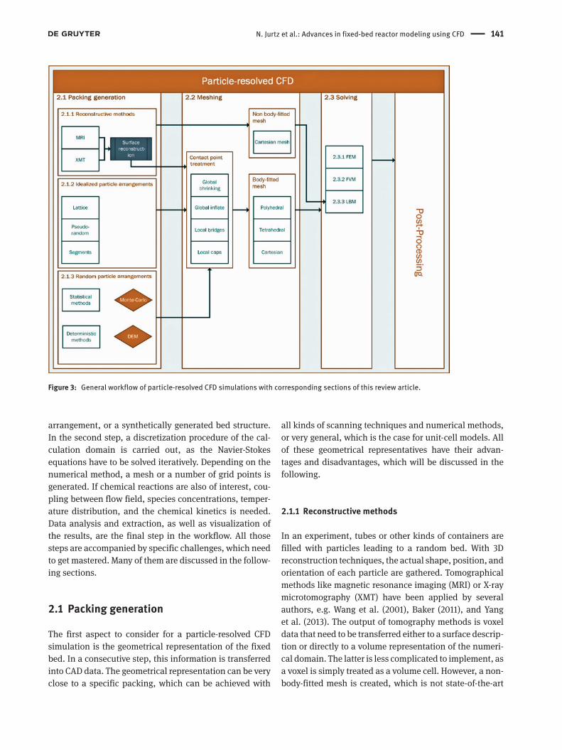
While in the early years, the use of DEM was limited to spherical particles, for which the original model was for-mulated, nowadays, it can also be used for non-spherical shapes. Figure 4 shows different approaches that can be applied to model non-spherical particles. One of the ear-liest developments was the approximation by a so-called composite particle. The desired shape of the non-spher-ical body is approximated by a user-defined amount of spheres, which retain their position with each other. That composite particle can be created either manually or by the use of Monte-Carlo-based automation methods. For
simple shapes, it is beneficial to create the composite particle manually, as it is a more efficient method. If the shape gets more complex, an automated procedure can be applied. It has to be mentioned that the more DEM spheres are used to approximate the desired shape, the more com-putational time is required. Furthermore, the edges of the original particle shape are not represented, as the shape is approximated with spheres. This is a disadvantage of the composite particle approach. Kodam et al. (2010a,b) developed and validated a sophisticated contact detection algorithm for genuine cylindrical particles. For different contact scenarios, they deducted equations to calculate the overlap, location, and normal vector of the contact point between two cylindrical particles or between a par-ticle and a planar wall. Feng et al. (2017) generalized this approach and developed a framework where a full exploi-tation of the axisymmetrical property of the cylinders is used to detect the contacts. Their method also works for the interaction of cylinders with spheres or half-spheres.
The first packing of cylindrical particles was presented by Bai et al. (2009). The authors used the composite-par-ticle approach and generated a bed consisting of 82 par-ticles investigating fluid dynamics. If composite particles are used, a crucial point for the accuracy is the number of DEM particles approximating the original shape.
A B C
Figure 4: Different kinds of DEM particles forming a packed bed.(A) Spherical. (B) Composite and (C) Cylindrical.
N. Jurtz et al.: Advances in fixed-bed reactor modeling using CFD 145
Caulkin et al. (2015) compared different particle repre-sentations that differed in their edge roundness, surface roughness, and restitutional behavior with experimental results. It was shown that an adequate approximation of sharp edges is needed to get satisfying results. Seventy-nine spheres per shape were needed for an acceptable characterization of the particle behavior.
In the last years, DEM has been extensively applied by several authors to create fixed beds with particles of different shapes. Table 1 summarizes the most important work on numerical methods in the field of fixed-bed reac-tors with random particle arrangement. Special attention is paid to particle shape and packing method and whether the generated bed morphology was validated against experimental results or against correlations.
2.2 Meshing
The discussed packing-generation methods provide either information on the particle position and orientation or a voxel representation of the bed geometry is given. In the first case, an overall CAD model of the fixed bed can be generated by placing one by one a CAD description of the individual particle based on the position and orientation data. If voxel data are used, either a surface-reconstruc-tion algorithm needs to be applied for creating CAD data or the voxel data can directly be utilized as a non-body-fitted hexahedral volume mesh [see Yang et al. (2013)].
Depending on the kind of numerical solver, the geo-metrical representation needs to get spatially discretized by a mesh with cells of a specific type. Different mesh types are depicted in Figure 5. Fundamentally, two catego-ries of meshes can be distinguished, i.e. structured and unstructured meshes. Figure 5A shows an example of a curvilinear structured grid where every node is explicitly defined according to the specified algorithm. That mesh type is numerically very efficient but obviously not appli-cable for complex geometries like fixed-bed reactors. For that kind of applications, unstructured meshes like the ones depicted in Figure 5B–F are much more advanta-geous. For different numerical methods, other mesh types are applicable or preferred.
For simulations based on the Lattice-Boltzmann method (LBM), typically Cartesian meshes are applied. At curved boundaries, a cut-cell approach according to Figure 5D can be used to retain the geometrical features. This is an efficient meshing strategy especially for complex geometries. For LBM, there is no need to calculate cell face fluxes. This method also works stably if the trimmed cells collapse at the particle-particle and particle-wall contact
points. For the finite-element method (FEM), most often, tetrahedral or hexahedral meshes similar to Figure 5B and C are used. For finite-volume method (FVM) codes, all mesh types depicted are at least applicable, besides the Cartesian cut-cell approach. Although many authors, as shown in Table 1, still use tetrahedral meshes, Peric (2004) showed that polyhedral cells tend to have less numerical dissipation. In addition, they converge faster compared with tetrahedral cells and are well suited for complex geometries involving tortuous flow. It is the best practice to use layers of prismatic cells, as can be seen in Figure 5F, at all fluid wall boundaries including the parti-cles to resolve the boundary layers.
In reality, randomly packed particles inside a reactor tube touch their neighboring particles or the tube wall. Between spherical particles, contact points occur. Con-trarily, non-spherical particles stay in contact with other particles or the wall with contact points, lines, or areas, see Figure 6. Whatever cell type is chosen, the meshing close to particle-particle and particle-wall contacts is a true challenge. If no modification is carried out, the low cell quality at the contacts will lead to serious conver-gence issues during the simulation. Figure 6 summarizes different modes of contacts in packed beds and common modification strategies.
The modifying approaches can be classified into global and local geometrical modifications. The global shrinking method was one of the first approaches that have been developed and reported for beds of spheres (Esterl et al. 1998). All particles are shrunk by a certain amount leading to a small gap, which can be filled with volume cells of reasonable quality. This technique, also known as the global gaps method (Dixon et al. 2013b), has been utilized by several authors within the last years, see Table 1. Guardo et al. (2004) developed an alternative approach and inflated the spherical particles by a certain degree. As a consequence, the angle between pointy faces at the contact point is increased. The vicinity, where faces intersect, can be filled with cells of good quality. This method was later referred to as the global overlaps method (Dixon et al. 2013b). The global increasing or decreasing of the particle size is a critical step, as it modi-fies the geometric representation significantly. This can be easily understood by the following estimate: taking the pressure drop correlation by Ergun (1952) in the fully turbulent flow regime for a porosity of ε = 0.4, changing the void fraction by 2.5% results in a deviation regarding the pressure drop of 10%. As the porosity is proportional to the particle diameter by 3
p ,dε ∝ this means that chang-ing the particle size by 1.35% will change the porosity by 2.5% and leads to a deviation of the pressure drop of

146 N. Jurtz et al.: Advances in fixed-bed reactor modeling using CFD
Tabl
e 1:
Pub
licat
ions
on
rand
omly
pac
ked
beds
of t
he la
st 10
year
s.
Publ
icat
ion
Pa
rtic
le s
hape
Pa
ckin
g m
etho
d
Mes
h ty
pe
Cont
act m
odifi
catio
n
Solv
er
Mor
phol
ogy
valid
atio
n
DEM
-bas
ed w
ork
Au
gier
et a
l. (2
010)
Sp
here
So
ft-sp
here
DEM
Te
trahe
dral
Gl
obal
shr
inki
ng
FVM
Ye
s
Bai e
t al.
(200
9)
Sphe
re, c
ylin
der
So
ft-sp
here
DEM
Te
trahe
dral
Gl
obal
shr
inki
ng
FVM
No
Be
hnam
et a
l. (2
013)
Sp
here
So
ft-sp
here
DEM
Te
trahe
dral
Gl
obal
shr
inki
ng
FVM
Ye
s
Bocc
ardo
et a
l. (2
015)
Sp
here
, cyl
inde
r, tri
lobe
s
Surfa
ce m
esh
base
d He
xahe
dral
Lo
cal b
ridge
s
FVM
Ye
s
Caul
kin
et a
l. (2
009b
)
Cylin
der,
Rasc
hig
ring,
Pal
l rin
g
Pixe
l-bas
ed D
EM
–
–
–
Yes
Ca
ulki
n et
al.
(201
5)
Cylin
der
So
ft-sp
here
DEM
–
–
–
Ye
s
Dixo
n et
al.
(201
2b)
Sp
here
So
ft-sp
here
DEM
Te
trahe
dral
Gl
obal
shr
inki
ng, l
ocal
brid
ges
FV
M
Yes
Ep
ping
er e
t al.
(201
1)
Sphe
re
Soft-
sphe
re D
EM
Poly
hedr
al
Loca
l cap
s
FVM
Ye
s
Eppi
nger
et a
l. (2
014b
)
Cylin
der,
Rasc
hig
ring,
four
-hol
e cy
linde
r So
ft-sp
here
DEM
Po
lyhe
dral
Lo
cal c
aps
FV
M
Yes
Ep
ping
er e
t al.
(201
6)
Sphe
re
Soft-
sphe
re D
EM
Poly
hedr
al
Loca
l cap
s
FVM
No
Ku
roki
et a
l. (2
007)
Sp
here
So
ft-sp
here
DEM
Te
trahe
dral
Lo
cal b
ridge
s
FVM
No
Ku
roki
et a
l. (2
009)
Sp
here
So
ft-sp
here
DEM
Te
trahe
dral
Lo
cal b
rdig
es
FVM
No
Oo
kaw
ara
et a
l. (2
007)
Sp
here
So
ft-sp
here
DEM
Te
trahe
dral
Lo
cal b
ridge
s
FVM
Ye
s
Rebu
ghin
i et a
l. (2
017)
Sp
here
So
ft-sp
here
DEM
Te
trahe
dral
Lo
cal b
ridge
s
FVM
No
Th
euer
kauf
et a
l. (2
006)
Sp
here
So
ft-sp
here
DEM
–
–
–
Ye
s
Toui
tou
et a
l. (2
014)
Sp
here
So
ft-sp
here
DEM
Te
trahe
dral
No
t spe
cifie
d
FVM
No
W
ehin
ger e
t al.
(201
5a)
Sp
here
So
ft-sp
here
DEM
Po
lyhe
dral
Lo
cal c
aps
FV
M
Yes
W
ehin
ger e
t al.
(201
5b)
Sp
here
, cyl
inde
r, Ra
schi
g rin
g
Soft-
sphe
re D
EM
Poly
hedr
al
Loca
l cap
s
FVM
No
W
ehin
ger e
t al.
(201
6b)
Sp
here
So
ft-sp
here
DEM
Po
lyhe
dral
Lo
cal c
aps
FV
M
Yes
W
ehin
ger e
t al.
(201
7a)
Cy
linde
r
Soft-
sphe
re D
EM
Poly
hedr
al
Loca
l cap
s
FVM
No
Xu
et a
l. (2
006)
Cy
linde
r
Pixe
l-bas
ed D
EM
–
–
–
Yes
Mon
te-C
arlo
-bas
ed w
ork
Au
wer
da e
t al.
(201
0)
Sphe
re
Mon
te-C
arlo
–
–
–
Ye
s
Atm
akid
is a
nd K
enig
(200
9)
Sphe
re
Mon
te-C
arlo
Te
trahe
dral
Gl
obal
shr
inki
ng
FVM
Ye
s
Atm
akid
is a
nd K
enig
(201
2)
Sphe
re
Mon
te-C
arlo
Te
trahe
dral
Gl
obal
shr
inki
ng
FVM
No
Ca
ulki
n et
al.
(200
8)
Sphe
re, c
ylin
der,
Rasc
hig
rings
M
onte
-Car
lo, H
ybrid
Ca
rtesi
an
Not n
eede
d
LBM
Ye
s
Caul
kin
et a
l. (2
009a
)
Cylin
der,
Rasc
hig
ring,
four
-hol
e cy
linde
r M
onte
-Car
lo, H
ybrid
–
–
–
Ye
s
Caul
kin
et a
l. (2
009b
)
Cylin
der,
Rasc
hig
ring,
Pal
l rin
g
Hybr
id
–
–
–
Yes
Ca
ulki
n et
al.
(201
2)
Cylin
der,
Rasc
hig
ring,
trilo
be
Hybr
id
Carte
sian
No
t nee
ded
LB
M
Yes
Scan
ned
geom
etrie
s
Bake
r (20
11)
Cy
linde
r
MRI
He
xa- a
nd te
trahe
dral
s
Loca
l brid
ges
FV
M
No
Mot
lagh
and
Has
hem
abad
i (20
08)
Cylin
der
Ph
otog
raph
y
Tetra
hedr
al
No m
odifi
catio
n
FEM
No
Ya
ng e
t al.
(201
3)
Sphe
re
MRI
He
xahe
dral
, pol
yhed
ral
Loca
l cap
s
FVM
No

N. Jurtz et al.: Advances in fixed-bed reactor modeling using CFD 147
10%. Several authors encountered that issue. Augier et al. (2010) and Atmakidis and Kenig (2009) reported devia-tions of more than 15% regarding the calculated pressure drop in comparison with correlations. Bai et al. (2009) avoided the problem by introducing a porosity correction factor. That might be practicable, if one is just interested in the pressure drop of the system. However, it will lead to significant errors for properties that rely on a correct predicted flow field. This indicates that the geometrical modifications to avoid the contact problem should be reduced to a minimum.
Therefore, Ookawara et al. (2007) and Eppinger et al. (2011) proposed local acting geometry modifications. The former developed a local strategy by placing small cylin-ders between the center of touching spheres, i.e. the local bridges method. The particles and bridging cylinders were united afterwards and subtracted from the container to extract the fluid volume. On the contrary, Eppinger et al. (2011) introduced small voids in the vicinity of the contact points in a bed of spheres by a sophisticated surface-meshing technique, i.e. the local caps method. During the surface re-meshing process, the algorithm detects, if
faces are in proximity to each other. If a certain threshold is exceeded, the meshing algorithm projects the vertices along their connecting line to reach the specified thresh-old. The resulting space is filled with a defined number of volume cells of good quality. It should be avoided to fill the gaps with an unnecessarily large number of cell layers. Instead, only two layers should be used. As each layer is adjacent to a no-slip boundary condition, this strategy prevents unrealistic high flow velocities near the contact points. Regarding the calculated pressure drop, both methods show good results and are in good agree-ment with correlations and experimental values by ±10% (Ookawara et al. 2007, Eppinger et al. 2011, Wehinger et al. 2015a). For non-spherical particles, the situation is more complex, as contact points, lines, and areas occur. Wehinger et al. (2017a) investigated the effects of contact modifications in a bed of cylinders by using the caps and bridges method for line and area contacts and caps and united method for overlaps resulting from composite DEM particles. The proposed method detects the different contact modes in a packed bed and modifies them locally. The bridges method only works for cylinder-like particles
Figure 5: Different mesh types.(A) Curviliniear structured. (B) Tetrahedral. (C) Mixed hexahedral. (D) Cartesian cut-cell. (E) Polyhedral and (F) Polyhedra with prism layers.

148 N. Jurtz et al.: Advances in fixed-bed reactor modeling using CFD
including those with internal voids as an algebraic relation is needed to determine the type of contact. The local caps method is more flexible and applicable to particles with internal voids [see Eppinger et al. (2014a) and Wehinger et al. (2015b)] and shapes that are not cylinder-like as tri-lobes. Independent of the contact type, the meshing algo-rithm automatically detects the faces that are in proximity to each other and creates a small gap.
If heat transfer is incorporated, both approaches show significant differences compared to each other. Figure 24 offers an overview of the different heat transfer mechanisms in a fixed bed of particles. It is obvious that the local caps and the local bridges method will lead to different results regarding the particle-particle and par-ticle-wall heat transfer by conduction through the con-tacts. By introducing the small space at the contact, the local caps approach neglects the inter-particle conduc-tion. Nevertheless, it was shown by Slavin et al. (2000, 2002) that heat transfer by inter-particle conduction can be neglected, if particles show non-plastic behavior and are not compressed. The numerical heat transfer study of Eppinger et al. (2014b) and Wehinger et al. (2016b) showed that the local caps meshing approach leads to results that show good agreement with experimental data concern-ing radial and axial temperature profiles. As reported
by Dixon et al. (2013b) and Wehinger et al. (2017a), the local bridges approach leads to an overestimation of the radial heat transfer if the thermal conductivity of the bridges is not adapted to replace the original particle-fluid-particle heat transfer. As a difficulty remains the choice of the thermal conductivity of these bridges. For spherical particles, Dixon et al. (2013b) developed a rela-tionship to calculate the effective thermal conductivity of the bridges. However, for non-spherical particles, this is still a matter of on-going research. It might be attractive to use this variable as fitting parameter, but this should definitely be avoided as it contradicts the philosophy of first principle modeling. Furthermore, the diameter of the bridges can be a crucial parameter. Dixon et al. (2013b) investigated the impact this parameter has on the pres-sure drop and heat transfer. They found that for flow or pressure drop, the bridge diameter should be below 20% of dp for particle-particle contacts and below 30% of dp for particle-wall contacts. If heat transfer is taken into account, the bridges should not exceed a diameter of 20% of dp for Rep ≤ 2000 or 10% of dp for higher Reynolds numbers. Rebughini et al. (2016) studied the impact of the bridge size for reactive CFD simulations of heteroge-neous catalytic fixed-bed reactors. They concluded that the conversion is independent of the bridge diameter if
Figure 6: Modes of contacts in packed beds (top) and modification strategies (bottom).Reprinted with permission from Wehinger et al. (2016b). Copyright (2016) American Chemical Society.

N. Jurtz et al.: Advances in fixed-bed reactor modeling using CFD 149
the bridge-to-particle diameter ratio is chosen accord-ing to the fluid dynamic recommendation of Dixon et al. (2013b).
As a summary, the modification of the bed shape should be minimized. Hence, local contact modifications should be preferred to global contact modifications. The local bridges method shows good results for pressure drop and heat transfer prediction. Still, the choice of the thermal conductivity of these bridges needs further inves-tigation. Contrarily, the local caps method shows strengths due to its low time consumption, numerical stability, and straightforward parameter selection. Dixon et al. (2012b) directly compared the caps and bridges methods and found for higher flow rates that there was little differences between the two methods, mainly because the heat trans-fer is dominated by convection in this case. For further clarification, more detailed experiments are needed of heat and mass transfer in low N packed beds with which CFD can be validated adequately.
2.3 Solving governing equations
The fundamental formulations of the governing equations for laminar and turbulent flow and the mathematics for solving those equations have been published broadly in the literature (Ferziger and Peric 1999, Ranade 2002, Kee et al. 2003). This and the following sections are intended to summarize the most important aspects for fixed-bed simulations and make no claim to be complete. The set of governing equations consists of conservation of total mass, conservation of momentum, conservation of mass of chemical species i, and conservation of energy in terms of specific enthalpy. Here, the set of equations is formulated in Cartesian coordinates assuming a laminar problem. For the turbulent formulation, see Section 2.4.
Conservation of total mass:
( ) 0,
tρ
ρ∂ + ∇⋅ =∂
ν
(4)
where ρ is the mass density, t is the time, and ν is the velocity.
Conservation of momentum:
( ) ( ) ,tρ
ρ ρ∂ + ∇⋅ = ∇ +
∂T gν
νν
(5)
where g is the gravity vector and the stress tensor T is written as:
2 2 ,3
p µ µ
= − + ∇⋅ + T I Dν
(6)
where μ is the mixture viscosity and I is the unit tensor, p is the pressure, and D is the deformation tensor:
1 [ ( ) ]2
T= ∇ + ∇D ν ν
(7)
Conservation of species i:
hom
g
( )( ) for 1, ,i
i i
YY R i N
tρ
ρ∂
+ ∇⋅ + ∇⋅ = =∂ ij …ν
(8)
with mass fraction Yi = mi/m of species i and total mass m. Ng is the number of gas-phase species. hom
iR is the net rate of production due to homogeneous chemical reactions. The diffusion mass flux of each species ji is described by the mixture-average formulation:
M, ,i iD Yρ= − ∇ij (9)
where DM,i is the effective diffusivity between species i and the remaining mixture M, which is defined as follows:
gM, g
1for 1, , .
/i
i Nj ijj i
XD i N
X D≠
−= =
∑…
(10)
The binary diffusion coefficients Dij can be obtained through polynomial fits CD-adapco (2014). Mi is the mole-cular weight of species i, and T, the temperature. The molar fraction Xi can be written as follows:
g
=1
1 ii
N j ij
j
YX
Y MM
=
∑
(11)
Conservation of energy in terms of specific enthalpy h:
( ) ( ) ( ) ( : ) ,hh h p St
ρρ
∂ + ∇⋅ + ∇⋅ − ∇ + ∇⋅ =∂
qν ν τ ν
(12)
where τ is the viscous stress tensor and Sh, a heat source. The diffusive heat transport q is given by:
g
1
N
ii
k T h=
= − ∇ + ∑ iq j
(13)
with thermal conductivity of the mixture k and mixture specific enthalpy h:
g
1( )
N
i ii
h Yh T=
= ∑
(14)
as a function of temperature hi = hi(T).Ideal gas can be assumed connecting pressure, tem-
perature, and density to close the governing equations:

150 N. Jurtz et al.: Advances in fixed-bed reactor modeling using CFD
g
1
Ni
i i
Yp RT
M=
= ∑ρ
(15)
Here Mi is the molecular weight of species i.As already mentioned in the previous section, differ-
ent numerical methods can be used to solve the balance equations, namely, FEM, LBM, and FVM. All have their benefits and disadvantages that make them more or less applicable for the simulation of fixed-bed reactors.
2.3.1 Finite-element method
Although FEM is rarely used for the simulation of fixed-bed reactors – to the authors knowledge, within the last decade, only Motlagh and Hashemabadi (2008) used the method for the simulation of fluid dynamic and heat transfer study of a very small packed bed (N = 2) contain-ing 10 cylindrical particles – a brief introduction of that method will be given.
FEM is a very flexible numerical method that is widely used for computational solid and structural mechanics (CSM) but can also be applied to fluid dynamic applica-tions. The idea behind FEM is to divide a body or fluid domain into a number of finite elements that are intercon-nected at nodal points. The result of FEM is a continuous function that is composed by numerous shape functions, each describing the behavior of the system in one element. The shape functions can have an arbitrary definition, but most often, linear or polynomial functions are used. The solution of the variables is stored in the nodal points.
Using the Galerkin formulation of FEM and assuming that the partial differential equation can be written using a differential operator L:
( )L fφ = (16)
and the solution φ can be estimated by a value φ by a linear combination of several shape functions θ:
1
ˆ .N
k kkbφ θ
=
= ∑ (17)
Here bk is a set of free parameters that are used to min-imize the residual
1
ˆ( ) .N
k kk
r L f L b fφ θ=
= − = − ∑
(18)
If the weighted residual method is used, a further restriction is that the overall integral of the residual multi-plied with a test function should vanish. This is called the weak formulation:
10.
N
k kk
r d L b f dΩ Ω
Ψ Ω θ Ψ Ω=
= − = ∑∫ ∫
(19)
The equation includes N unknown values for bk. Therefore, N different and linear independent test func-tions Ψk are needed to derive an equation system contain-ing N equations. A widely used approach is to set:
.k kΨ θ= (20)
The advantage of FEM is that it provides a rather gen-eralized framework for the solution of arbitrary problems. It is also known to show low numerical diffusion and is therefore suited for highly viscous or visco-elastic flow problems. On the other hand, FEM is a very memory-demanding method, which limits its usage.
2.3.2 Finite-volume method
FVM is a numerical approach to solve the governing equa-tions by the discretization of the numerical domain into a number of finite volumes, often called cells. The system of partial differential equations is integrated over each element and, by this, transferred into a system of alge-braic equations that can be solved. The governing equa-tion of a conserved quantity in its integral form can be written as follows:
.S S V
dS dS q dVρφ Γ φ⋅ = ∇ ⋅ +∫ ∫ ∫n n φν (21)
Equation (21) is valid for each cell and, therefore, the overall domain. By its definition, FVM is an inherently conservative numerical method. To gain an algebraic expression for each cell, the area and volume integrals in Eq. (21) need to be approximated.
The overall flux across the cell faces can be expressed as the sum of fluxes over each cell face k:
,
S SkkfdS fdS= ∑∫ ∫
(22)
where f represents the convective (ρφν · n) or diffusive (Γ∇φ · n) flux in the direction of the face normal. Figure 7 shows schematically a two-dimensional (2D) Cartesian mesh. It is common to use the compass notation to iden-tify the centers of the considered cell and its neighbors (P, N, S, W, E), the faces (n, s, w, e), and the vertices (nw, ne, se, sw).
The simplest approximation for the surface integral of the eastern face is given by the assumption that the mean face value of the variable is equal to its value in the center of the cell face:

N. Jurtz et al.: Advances in fixed-bed reactor modeling using CFD 151
ee e e eS
fdS f S f S= ≈∫ (23)
More complex approximations, leading to higher order methods, like the Trapezoidal rule and the Simp-son’s rule – which take into account information from neighboring cells – are also possible but are discussed elsewhere [see Ferziger and Peric (1999)].
To estimate the volume integral in Eq. (21), one approach can be to assume that the value stored in the cell center equals the mean value in the control volume:
,PVq dV q V q V
φ φ φ∆ ∆= ≈∫ (24)
Obviously, for the calculation of the convective and diffusive fluxes, variable values at the face centers are needed. Different methods exist to approximate the face values based on the cell values (e.g. upwind and central-differencing), which are extensively discussed by Ferziger and Peric (1999). The resulting algebraic equation system can subsequently be solved by applying appropriate numerical methods.
As it can be seen in Table 1, for the majority of the numerical work done in the field of fixed-bed reactors, FV technique is used nowadays. This is, on the one hand, related to its applicability on unstructured meshes and the progress that was made in the last decade regarding automated meshing algorithms. On the other hand, to its beneficial characteristics like noninvasive boundary con-ditions – as the variables are stored in the cell centers and the boundary condition acts on the surface – and the fact that the FVM conserves mass, energy, and momentum by definition.
Furthermore, the incorporation of additional relevant physical phenomena can easily be done by either solving
additional transport equations (e.g. heat and mass trans-fer, turbulence), including source terms (e.g. chemical reactions), or by applying special boundary conditions [e.g. conjugated heat transfer (CHT) and surface-to-sur-face radiation]. It is therefore the ideal framework for mul-tiphysics applications like fixed-bed reactors.
2.3.3 Lattice-Boltzmann method
LBM is compared to FVM and FEM not only as a different method to solve the system of partial differential equa-tions. The underlying physical perspective is completely different by using the kinetic theory of gases. The basis of this approach is the assumption that continuous mechanical phenomena are the result of statistical aver-aged effects on a molecular level. As not all molecules and interactions can be taken into account because of the immense numerical effort this would cause, only a limited number of representative particles are taken that are allowed to move on a discrete lattice. The exchange of momentum and energy is achieved by a sequential colli-sion step followed by the motion of the particles along the lattice – often called streaming.
For a 2D simulation, each particle has nine possi-ble directions to move, including the possibility to rest. Associated with each direction is a so-called microscopic velocity ei depicted in Figure 8A, where i = 0…8. For each direction, also a probability fi exists that the particle moves in this direction. During the collision, step rules are applied that need to conserve mass, momentum, and energy. This is done by applying a collision term Ω to the following equation:
( , ) ( , )if t f t Ω∗ = +x x (25)
Using the Bhatnagar-Gross-Krook (BGK) operator, the collision term Ω can be expressed as follows:
eq
,i if fT
Ω−
=ω
(26)
where ω is the relaxation time that is related to the kin-ematic fluid viscosity ν and eq
if is a local equilibrium dis-tribution in the direction of ei (see Figure 8B).
( , ) ( , ),i i i if c t t t f t∆ ∆ ∗+ + = xx e (27)
where c is the lattice speed .xct
∆∆
= A more comprehensive
discussion about the use of LBM in the field of CFD can be found in the study by Succi (2001).
Figure 7: Mesh topology and notation on a 2D Cartesian mesh.

152 N. Jurtz et al.: Advances in fixed-bed reactor modeling using CFD
In the early years, LBM has been extensively used by several authors like Zeiser et al. (2001, 2002), Freund et al. (2003, 2005), and Manjhi et al. (2006) for their flow and mass transfer simulations. Compared to other numeri-cal method in these days, LBM had the benefit that the meshing process was very efficient and that the contact point problem could easiely be avoided. The results pre-sented by Freund et al. (2003, 2005) showed that LBM is able to predict the pressure drop and the local flow field with a satisfactory accuracy. Compared to correlation, the calculated pressure drop showed a deviation of below ±10% and also the local velocity was in good agreement with Laser Doppler anemometry (LDA) data by Krischke (2001).
During the last decade, LBM got more and more replaced by FVM. This was driven not only by the inno-vations in the field of FVM, like major improvements in automated meshing and increasing computational power, but also due to limitations of the LBM; as men-tioned by Nijemeisland and Dixon (2004) and Freund et al. (2005), the main limitation of LBM is that simu-lations including CHT are almost impossible to do with LBM as either a more complex discretizations of the velocity space is needed or a separate distribution func-tion for the temperature needs to be incorporated. Both possibilities increase the numerical effort and tend to promote instabilities. Furthermore, as mentioned by Zeiser et al. (2002), LBM is an inherently transient numerical method, which makes its application on steady-state problems less efficient.
To the knowledge of the authors, only the work of Caulkin et al. (2008, 2012) used LBM within the last decade to show the possibility of running fluid dynamic
simulations of non-spherical particles like cylinders, tri-lobes, and Raschig rings.
2.4 Turbulence
Turbulence is characterized by strongly fluctuating 3D and unsteady eddies. It has a significant impact on the lateral mixing of all transport properties. The flow gets turbulent if the inertial forces become dominant com-pared to the viscous forces. The transition from laminar to turbulent flow does not happen instantly. Most often, a transition zone exists that can be characterized by a set of critical Reynolds numbers whose values depend on the physical system itself. According to Dybbs and Edwards (1984), the flow regime in fixed-bed reactors can be characterized using the Reynolds number based on the particle diameter and the interstitial velocity Re
ε
as follows:1. Re
ε < 1: Viscous flow regime. Pressure drop is a linear
function of the interstitial velocity.2. 10 ≤ Re
ε ≤ 150: Steady laminar inertial regime. Pres-
sure drop is a non-linear function of the interstitial velocity, and boundary layers are forming.
3. 150 ≤ Reε ≤ 300: Unsteady laminar inertial regime. The
flow shows oscillating behavior in the wake within the voids. At Re
ε = 250, laminar vortices start to form.
4. Reε > 300: Turbulent flow. Characterized by an
unsteady and chaotic flow.
Various numerical methods exist to describe turbulent effects in CFD. They differ in the amount of subgrid mod-eling that is done to account for turbulent eddies. The
Figure 8: D2Q9 LBM.(A) Microscopic velocities and (B) weighted by distribution function.
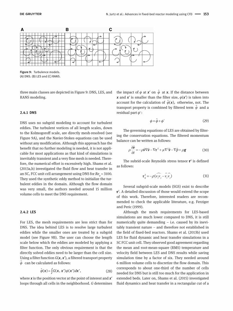
N. Jurtz et al.: Advances in fixed-bed reactor modeling using CFD 153
three main classes are depicted in Figure 9: DNS, LES, and RANS modeling.
2.4.1 DNS
DNS uses no subgrid modeling to account for turbulent eddies. The turbulent vortices of all length scales, down to the Kolmogoroff scale, are directly mesh-resolved (see Figure 9A), and the Navier-Stokes equations can be used without any modification. Although this approach has the benefit that no further modeling is needed, it is not appli-cable for most applications as that kind of simulations is inevitably transient and a very fine mesh is needed. There-fore, the numerical effort is excessively high. Shams et al. (2013a,b) investigated the fluid flow and heat transfer in an SC, FCC unit cell arrangement using DNS for Rep ≈ 3100. They used the synthetic eddy method to initialize the tur-bulent eddies in the domain. Although the flow domain was very small, the authors needed around 15 million volume cells to meet the DNS requirement.
2.4.2 LES
For LES, the mesh requirements are less strict than for DNS. The idea behind LES is to resolve large turbulent eddies while the smaller ones are treated by a subgrid model (see Figure 9B). The user can choose the length scale below which the eddies are modeled by applying a filter function. The only obvious requirement is that the directly solved eddies need to be larger than the cell size. Using a filter function G(x, x′), a filtered transport property φ can be calculated as follows:
ˆ ( ) ( , ) ( ) ,G dφ φ= ′ ′ ′∫x x x x x (28)
where x is the position vector at the point of interest and x′ loops through all cells in the neighborhood. G determines
the impact of φ at x′ on φ at x. If the distance between x and x′ is smaller than the filter size, φ(x′) is taken into account for the calculation of ˆ ( ),φ x otherwise, not. The transport property is combined by filtered term φ and a residual part φ*:
ˆφ φ φ∗= + (29)
The governing equations of LES are obtained by filter-ing the conservation equations. The filtered momentum balance can be written as follows:
2ˆ ˆˆ ˆ ˆS p
tρ ρ µ ρ
∂ = − ∇ − ∇ + ∇ − ∇ +∂
gνν ν τ ν
(30)
The subrid-scale Reynolds stress tensor τS is defined as follows:
( )Sij i j i jν ν ν ν= − − ρτ (31)
Several subgrid-scale models (SGS) exist to describe τS. A detailed discussion of those would extend the scope of this work. Therefore, interested readers are recom-mended to check the applicable literature, e.g. Ferziger and Peric (1999).
Although the mesh requirements for LES-based simulations are much lower compared to DNS, it is still numerically quite demanding – i.e. caused by its inevi-tably transient nature – and therefore not established in the field of fixed-bed reactors. Shams et al. (2013b) used LES for fluid dynamic and heat transfer simulations in a SC FCC unit cell. They observed good agreement regarding the mean and root-mean-square (RMS) temperature and velocity field between LES and DNS results while saving simulation time by a factor of six. They needed around 6 million volume cells to discretize the flow domain. This corresponds to about one-third of the number of cells needed for DNS but is still too much for the application in extended beds. Later on, Shams et al. (2015) investigated fluid dynamics and heat transfer in a rectangular cut of a
Figure 9: Turbulence models.(A) DNS. (B) LES and (C) RANS.
154 N. Jurtz et al.: Advances in fixed-bed reactor modeling using CFD
random packing consisting of around 20 spherical parti-cles using LES. The resulting mesh consisted of approxi-mately 18 million volume cells. It took them 6 months to reach statistical convergence on HPC using 120 processors (2.66 GHz). This truly indicates that there are some miles left to go to establish LES in the field of fixed-bed reactors.
2.4.3 RANS
In the majority of academic and industrial applications, RANS turbulence models are used. RANS models do not resolve the turbulent eddies; instead, they are modeled via subgrid model (see Figure 9C). This leads to a tre-mendous reduction of the numerical effort as there is no more need to run a transient simulation and the cell count can be decreased significantly. Fluid dynamic simulation using RANS models can be conducted within hours on a local workstation for fixed beds with a few thousand of particles. The idea behind that class of turbulence model is that a property can be decomposed into its time-aver-aged value and a fluctuating component:
( , ) ( ) ( , )i i ix t x x tφ φ φ= + ′ (32)
If Eq. (32) is applied to the governing equations, one gets the RANS equations:
( ) 0ρ∇ =ν (33)
2 ,t p
tρ ρ µ ρ
∂ = − ∇ − ∇ + ∇ − ∇ −∂
gνν ν τ ν
(34)
where τt is the Reynolds stress tensor:
x x x y x z
t y x y y y z
z x z y z z
ν ν ν ν ν ν
ρ ν ν ν ν ν ν
ν ν ν ν ν ν
′ ′ ′ ′ ′ ′
= × =′ ′ ′ ′ ′ ′ ′ ′
′ ′ ′ ′ ′ ′
ρ ρ ρρ ρ ρρ ρ ρ
τ ν ν
(35)
The components of τt need to be determined to close the equation system. For this, different approaches have been developed in the past, such as the Reynolds stress model (RSM) or eddy viscosity models. The main differ-ence between both approaches is that the eddy viscos-ity models assume isotropic turbulence, while RSM can model anisotropic turbulent behavior. Nevertheless, the class of eddy viscosity models is heavily used in academia and the industry and will therefore be discussed further.
To describe the Reynolds stress tensor, the Boussin-esq approximation is used:
2[ ( ) ] ,3
Tt t kµ ρ δ= ∇ + ∇ −τ ν ν
(36)
where μt is the turbulent viscosity and k is the turbulent kinetic energy, defined as follows:
1 | |2
k = ′ν
(37)
To close the system of equations, an expression for μt is needed. For this reason, different models were devel-oped in the past that can be categorized in zero-, one- and two-equation turbulence models. For the simulation of fixed-bed reactors, almost entirely the class of two-equa-tion models has been used in the past and is therefor of interest. This class can be divided into the group of k − ε and k − ω turbulence models. Depending on which group is used, μt can be expressed as follows:
2
tkC
µµ ρ
ε=
(38)
or
.t
kµ ρ
ω=
(39)
Here, ε is the turbulent dissipation rate, and ω, the specific dissipation. A great number of models exist to determine k and ε, respectively, ω by solving transport equation for each parameter. In the diffusion term of the energy and mass conservation equation, an additional turbulent thermal conductivity and diffusion coefficient is introduced whose values are correlated with the tur-bulent viscosity by using a specified turbulent Schmidt
tt
t
ScDµ
ρ= and Prandtl number .t p
tt
cPr
µ
λ= As a detailed
discussion of the several models does not fall within the scope of this work, the interested reader is referred to the relevant literature, e.g. Wilcox (2006).
Various authors tested different RANS turbulence models and investigated their applicability to the field of fixed-bed reactors. Coussirat et al. (2007) compared RSM against the Standard k − ε and the Spalart-Allmaras one-equation model regarding pressure drop and particle Nusselt number in a bed of 44 spheres. The authors vali-dated their numerical results against correlation data and showed that, if a reasonable mesh resolution is used, all tested turbulence models achieve similar satisfying results concerning the particle Nusselt number but the Spalart-Allmaras model tends to under-predict the pressure drop for a wide range of Reynolds numbers. Lee et al. (2007) and Dixon et al. (2011) investigated the heat transfer for a single particle. The former authors tested LES, RSM, and several eddy viscosity models and found that compared to LES, the k − ω model performs best and produces com-parable results, while the latter recommends the use of

N. Jurtz et al.: Advances in fixed-bed reactor modeling using CFD 155
the k – ω − SST turbulence model as it predicts drag coef-ficient, Nusselt number, and particle temperature reason-able well. Most authors use k − ε models and its derivatives and achieve very good results even for simulations includ-ing heat transfer, mass transfer, or chemical reactions [see Eppinger et al. (2014b), Wehinger et al. (2015a, 2016b, 2017a), and Dixon et al. (2012b)].
2.5 Modeling of chemical surface reactions
Most of the reacting systems, which are realized with fixed-bed reactors, involve predominantly reactions occurring only at the surface of the catalytic pellets. As illustrated in Figure 10, physical as well as chemical processes take place. The fundamental chemical processes in a hetero-geneous reaction system can be described with different extent. Detailed surface reaction mechanisms are so-called microkinetic models. Those models indicate the use of a detailed reaction mechanism describing elementary-like processes happening on a catalyst (Salciccioli et al. 2011). Physical phenomena occurring in the pores of the
catalyst pellet (pore diffusion) or through the film around the pellet (film diffusion) together with microkinetics are lumped into so-called macrokinetics. In the following, the fundamentals of modeling chemical surface reactions and their surrounding are summarized briefly. The interested reader is referred to Cortright and Dumesic (2001), Kee et al. (2003), Bird et al. (2007), and Deutschmann (2008).
2.5.1 Description of heterogeneous catalysis
Adsorption processes can be distinguished between phy-sisorption and chemisorption. Physisorption is character-ized by weak Van der Waals forces between adsorbate and surface (8–30 kJ/mol). Chemisorption leads to a chemical bonding between adsorbate and surface, which is char-acterized by high adsorption enthalpies (40–800 kJ/mol) (Kee et al. 2003). The high bonding energy of the adsorbed molecule can lead to dissociation of the molecule, see Figure 11.
Besides measuring rate constants for adsorption pro-cesses, collision theory can be applied in terms of gas-phase molecules striking the surface per unit area per unit time Fi (Cortright and Dumesic 2001):
,2
ii
i B
pF
M k Tπ=
(40)
where kB is the Boltzmann constant and pi is the partial pressure of species i.
The rate of adsorption can then be expressed by mul-tiplying Fi with the sticking coefficient Si, i.e. the prob-ability that collision with the surface is accompanied with adsorption:
adsi i is F S= ⋅ (41)
As the sticking coefficient depends on surface cover-age Θ and temperature T, it can be defined as the product Figure 10: Physical and chemical processes at a catalytic pellet.
A B
Figure 11: Two adsorption mechanisms shown here; simple and dissociative.(A) Simple adsorption and desorption. (B) Dissociative adsorption and associative desorption. Reprinted with permission from Wehinger (2016).
156 N. Jurtz et al.: Advances in fixed-bed reactor modeling using CFD
of its initial value 0,iS i.e. on a clean surface, and the surface coverage (Cortright and Dumesic 2001). The result-ing expression for the rate of adsorption is as follows:
ads 0
12sN
i i i jji
RTs S cM
Θπ =
= ∏
(42)
with ci is the molar concentration.Reactions between or with adsorbates can be
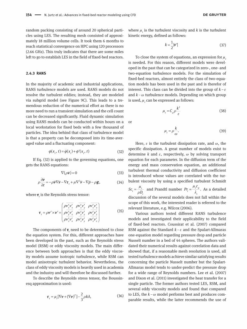
expressed by two different mechanisms, i.e. Lang-muir-Hinshelwood and Eley-Rideal, see Figure 12. The Langmuir-Hinshelwood mechanism assumes that both reactants are adsorbed at the catalytic surface. On the other hand, the Eley-Rideal mechanism describes the reaction between one gas phase molecule and a surface adsorbed species.
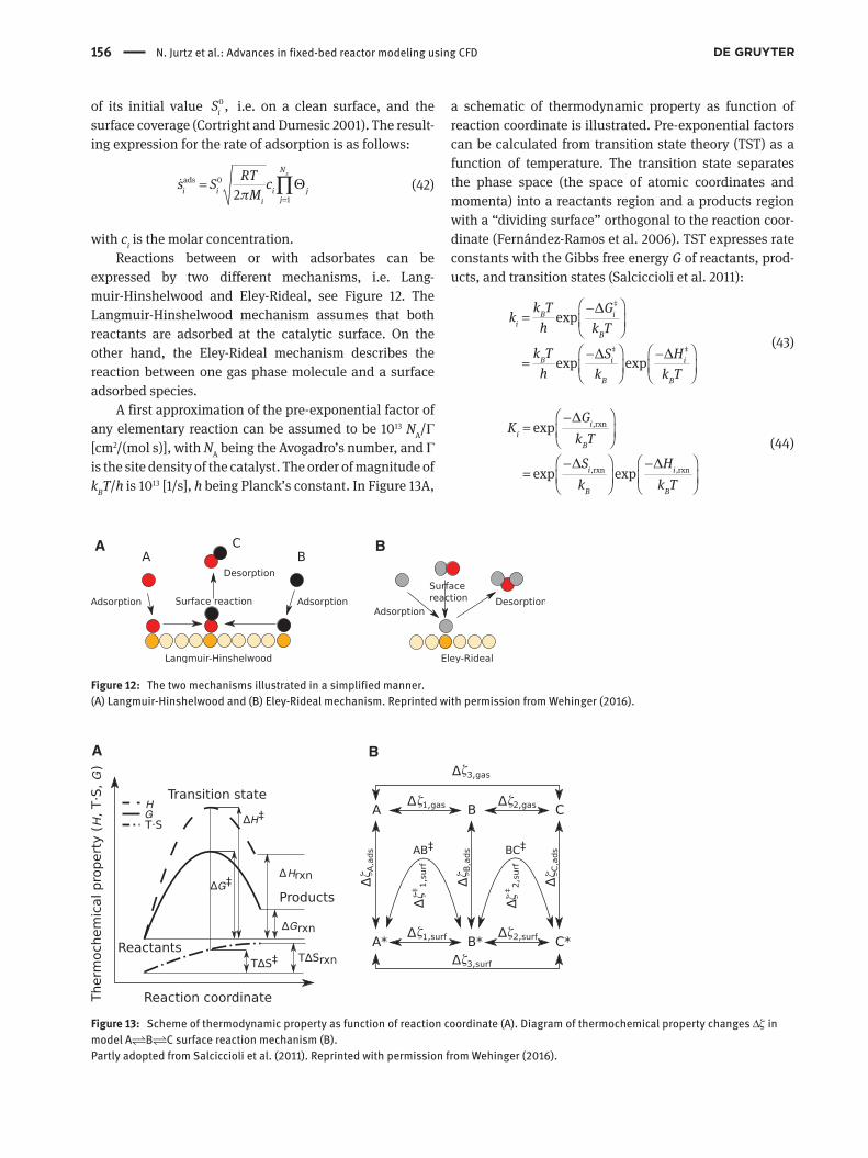
A first approximation of the pre-exponential factor of any elementary reaction can be assumed to be 1013 NA/Γ [cm2/(mol s)], with NA being the Avogadro’s number, and Γ is the site density of the catalyst. The order of magnitude of kBT/h is 1013 [1/s], h being Planck’s constant. In Figure 13A,
a schematic of thermodynamic property as function of reaction coordinate is illustrated. Pre-exponential factors can be calculated from transition state theory (TST) as a function of temperature. The transition state separates the phase space (the space of atomic coordinates and momenta) into a reactants region and a products region with a “dividing surface” orthogonal to the reaction coor-dinate (Fernández-Ramos et al. 2006). TST expresses rate constants with the Gibbs free energy G of reactants, prod-ucts, and transition states (Salciccioli et al. 2011):
‡
‡ ‡
exp
exp exp
B ii
B
B i i
B B
k T Gkh k T
k T S Hh k k T
∆
∆ ∆
−=
− −=
(43)
,rxn
,rxn ,rxn
exp
exp exp
ii
B
i i
B B
GK
k T
S Hk k T
∆
∆ ∆
−=
− −=
(44)
A B
Figure 12: The two mechanisms illustrated in a simplified manner. (A) Langmuir-Hinshelwood and (B) Eley-Rideal mechanism. Reprinted with permission from Wehinger (2016).
A B
Figure 13: Scheme of thermodynamic property as function of reaction coordinate (A). Diagram of thermochemical property changes Δζ in model ABC surface reaction mechanism (B).Partly adopted from Salciccioli et al. (2011). Reprinted with permission from Wehinger (2016).

N. Jurtz et al.: Advances in fixed-bed reactor modeling using CFD 157
In the two equations above, ki describes the irrevers-ible elementary reaction rate constant of reaction i in dependency of the change in Gibbs free energy to transi-tion state ‡ ,iG∆ the change in entropy ‡ ,iS∆ as well as the change in enthalpy ‡
iH∆ from reactant to transition state. Eq. (44) relates the equilibrium constant Ki of reaction i to the change in free energy of reaction and entropy and enthalpy of reaction.
2.5.2 Modeling rates of heterogeneous catalysis
In principle, heterogeneously catalyzed gas-phase reactions can be described entirely by the sequence of elementary reaction steps of the catalytic cycle consist-ing of adsorption, surface reaction, and desorption, as described in the above section. However, the level of detail can differ from macroscopic description (power-law kinetics) to the molecular level [density functional theory (DFT)]. In Table 2, the most common methods of modeling rates of heterogeneous catalysis are summarized.
2.5.2.1 Power-law kineticsIn the past, the power-law functional form was the usual type of rate expression:
eff /eff eff eff, with .E RTa b
A Bs k C C k A e−= = (45)
In power-law kinetics, the molar net production rate s is estimated by an effective rate constant (keff), reaction order (a, b), as well as an effective activation energy (Eeff). Although this type of kinetics is represented by funda-mental limitations and a lack of predictive order, it is still commonly used in reactor and process design applica-tions. The reason is the small amount of parameters that have to be regressed to a limited experimental data set.
2.5.2.2 Langmuir-Hinshelwood-Hougen-Watson (LHHW) kinetics
For many years, LHHW kinetics had been a popular simpli-fied approach to describe heterogeneous catalysis in tech-nical reactors. Developing a LHHW kinetics starts with a detailed reaction mechanism. In the following step, a priori assumptions are made about fast and slow reaction steps. In general, one rate-determining step (RDS) is identified and it is assumed that adsorption-desorption processes of reactants and products are in partial equilibrium (PE). Surface coverages are referred to partial pressures in the gas phase by means of Langmuir adsorption isotherms. Ta
ble
2: M
etho
ds o
f mod
elin
g ra
tes
of h
eter
ogen
eous
cata
lysi
s.
Mod
elin
g m
etho
d
Sim
plifi
catio
ns
Appl
icat
ion
Ab in
itio
calc
ulat
ion
M
ost f
unda
men
tal a
ppro
ach
Si
mpl
e ch
emic
al s
yste
ms
DFT
Re
plac
emen
t of t
he N
ele
ctro
n w
ave
func
tion
by th
e el
ectro
n de
nsity
Dy
nam
ics
of re
actio
ns, a
ctiv
atio
n ba
rrie
rs, a
dsor
bed
stru
ctur
es, f
requ
enci
es(K
inet
ic) M
onte
Car
lo
Negl
ect o
f det
ails
of d
ynam
ics
Ad
sorb
ate-
adso
rbat
e in
tera
ctio
ns o
n ca
taly
tic s
urfa
ces
and
nano
part
icle
sM
ean-
field
app
roxi
mat
ion
Negl
ect o
f det
ails
on
adso
rbat
e-ad
sorb
ate
inte
ract
ions
M
icro
kine
tic m
odel
ing
of ca
taly
tic re
actio
ns in
tech
nica
l sys
tem
sLH
HW k
inet
ics
Ne
ed o
f rat
e-de
term
inin
g st
ep
Mod
elin
g of
cata
lytic
reac
tions
in te
chni
cal s
yste
ms
Pow
er-la
w k
inet
ics
Ne
glec
t of a
ll m
echa
nist
ic a
spec
ts
Scal
e-up
and
reac
tor d
esig
n fo
r bla
ck-b
ox s
yste
ms
Adop
ted
from
Kun
z et a
l. (2
012)
.

158 N. Jurtz et al.: Advances in fixed-bed reactor modeling using CFD
The kinetic parameters are determined by fitting the rate equations to (a limited number of) experimental data. Due to this procedure, multiple rate expressions can describe the same set of data with similar statistics, i.e. rate expres-sion multiplicity (Prasad et al. 2009). Moreover, multiple parameter values, describing experimental data reason-ably well, may be present for the same rate expression, i.e. rate constant multiplicity. Assuming that the rate expres-sion reproduces the data reasonably accurate, the physics might be wrong, i.e. wrong RDS and PE, or the parameters are physically irrelevant. In addition, LHHW kinetics is typically restricted to one smaller range of operating con-ditions where the rate changes monotonically regarding one parameter. Salciccioli et al. (2011) compared different values of heats of adsorption from LHHW kinetics and from DFT or experiments. In most cases, the parameters from LHHW kinetics were physically unrealistic, even though the kinetics describes the experimental data fairly well in the investigated range. In can be concluded that with LHHW kinetics, it is possible to reproduce experi-mental data, but the fundamental mechanism might still be undesignated.
2.5.2.3 Mean-field approximationThe catalytic processes at the reacting surface occur at much smaller time and length scales as the surrounding flow field. An efficient model coupling CFD and micro-kinetics is the mean-field approximation. On the other hand, there are recent attempts to couple CFD with the computationally expensive kinetic Monte Carlo simula-tions (Majumder and Broadbelt 2006, Matera and Reuter 2009, Schaefer and Jansen 2013, Matera et al. 2014). The discussion of kMC is out of scope of this review. The inter-ested reader is referred to Sabbe et al. (2012) and Schaefer and Jansen (2013). The mean-field approximation model assumes uniformly distributed adsorbates and catalytic sites over a computational cell. Spatially localized effects, i.e. surface facets, surface defects, and coverage effects, as well as interactions between adsorbates, are neglected by using averaged values. The condition of the catalyst in a computational cell is determined by temperature T and a set of surface coverages Θi, which is defined as the frac-tion of surface covered by species i. Chemical reactions occurring at the catalytic surface are coupled via bound-ary conditions with gas-phase species concentration at the gas-surface interface. In most of the cases, the catalyti-cally active surface area cannot be resolved. For example, the catalytically active surface of a porous sphere is much larger than its geometric surface. In order to couple the external flow with the surface reactions, the relation
between catalytically active surface area to geometric surface area is needed (Fcat/geo). This value can be deter-mined experimentally, for example, by chemisorption measurements. Under steady-state conditions, gas-phase molecules of species i, which are produced/consumed at the catalytic surface by desorption/adsorption, have to diffuse from/to the catalyst (Kee et al. 2003):
het( ) iR=in j (46)
with the outward-pointing unit vector normal to the surface n and the diffusion mass flux ji. The heterogene-ous reaction term het
iR can be formulated as follows:
hetcat/geoi i iR F M s= (47)
with Mi as the molar weight, is as the molar net produc-tion rate of gas-phase species i, and Fcat/geo as the ratio of catalytic active area Acatalytic to geometric area Ageometric.
cat/geo catalytic geometric/ .F A A= (48)
The molar net production is results in:
g
11,
ssjk
k
N NK
i ik f jjk
s k cνν
+′
==
= ∑ ∏
(49)
where Ks is the number of surface reactions, cj is the species concentrations in [mol/m2] for the adsorbed species Ns and in [mol/m3] for the gas phase species Ng, respectively. In addition, the surface coverage Θ takes into account the surface site density Γ [mol/m2], represent-ing the maximum number of species that can adsorb on a unit surface area. Furthermore, a coordinate number σi expresses the number of surface sites, which are covered by this species:
1i i icΘ σ Γ−= (50)
The time-dependent variation of Θi can be written as follows:
i i ist
Θ σ
Γ
∂=
∂
(51)
Under steady-state conditions, the left side of Eq. (51) equals zero. The reaction rate expression can be modified by the concentration, or coverage, of some surface species Θi (Kee et al. 2003):
1
exp
10 exp
kk
k
sik kik
af k
Ni ii
ii
Ek A T
RT
RT
β
Θ µΘ
Θ⋅
=
−=
− ∏ η ε
(52)

N. Jurtz et al.: Advances in fixed-bed reactor modeling using CFD 159
with three extra coverage parameters, ηik, μik, and εik. The term with ηik represents a change of magnitude of the pre-exponential factor in dependency of surface coverage Θi. The term including μik indicates the modification of the surface reaction rate expression proportional to any arbi-trary power of surface coverage. The εik term represents a modification of the activation energy as a function of coverage.
The occurrence of adsorption reactions results in a modification of the conventional rate coefficient by refer-encing sticking coefficients:
0ads ,
2k
if
i
S RTkMτ πΓ
=
(53)
with 0iS as the initial (uncovered surface) sticking
coefficient and 1sN
jkjτ ν
== ′∑ as the sum of all the surface
reactant’s stoichiometric coefficients. For more details, see the study by Kee et al. (2003).
2.5.3 Thermodynamic consistency of microkinetics
Thermodynamic consistency of microkinetics is a very important aspect. However, many mechanisms in litera-ture do not prove it explicitly. Thermodynamic constraints of microkinetics can be formulated by four equations (Cortright and Dumesic 2001) proving, firstly, individual elementary reactions and, secondly, the overall net reac-tion. For individual elementary reactions, the following constraints have to be fulfilled:
,b ,fi i iE E H∆ ∆ ∆= − (54)
,b ,f ,fexp exp ,i i ii i i
G H SA A A
RT R∆ ∆ ∆ −
= =
(55)
where ΔEi,b is the backward activation energy, ΔEi,f is the forward activation energy, and ΔHi is the standard enthalpy change of the individual reaction step. Ai,b is the reverse pre-exponential factor, and Ai,f the forward pre-exponential factor, respectively. ΔGi is the change in standard Gibbs free energy of reaction i, and ΔSi is the change in entropy.
Applying Hess’ law, each reaction step can be formu-lated with a gas-phase reaction having the same stoichi-ometry. A net reaction that begins with gaseous reactants and ends with gaseous products can be described as a linear combination of several reactions. Thermodynamic constraints for the net reactions can be defined by the following:
,f ,b net( ) ( )i i i i
i iE E Hσ ∆ σ ∆ ∆− =∑ ∑
(56)
and
,f net net
,b
exp ,i
i
i i
A G HA RT
σ∆ ∆ −
= ∏
(57)
where the subscript “net” denotes the change in thermo-dynamic state properties from net reactants to net products (Salciccioli et al. 2011). Alternatively, the thermodynamic consistency is defined via the equilibrium constants of each elementary step, as well as the net reaction (Cortright and Dumesic 2001):
,for,eq net
,rev
,i
i ii
i i i
kK K
k
σ
σ
= =
∏ ∏
(58)
where Knet is the equilibrium constant of the overall stoichiometric reaction.
In Figure 13B, the relationship is illustrated between gas-phase and surface-phase thermochemical properties of gas and surface intermediates and transition states, denoted as ‡ for the simple ABC surface reaction mechanism. The variable ζ represents any of the ther-mochemical properties, i.e. free Gibbs energy G, entropy S, and enthalpy H. In the figure, Δζ3,gas represents the pro-perty change connected with the elementary gas-phase reactions; in this situation, Δζ3,gas = Δζ1,gas + Δζ2,gas.
Violation of thermodynamic consistency can lead to erroneous predictions of heat and mass. Enthalpic incon-sistency leads to incorrect solution of the energy balance. As a consequence, in a non-isothermal simulation, wrong temperatures are predicted and likewise wrong conver-sion. In an isothermal simulation, the temperatures are fixed; however, the enthalpic inconsistency leads to errors in the mass balance. On the other hand, inconsistency in terms of entropy is characteristic for a fundamental incon-sistency of pre-exponential factors. By defining both the forward and reverse reaction steps, an incorrect equilib-rium constant can be the result of thermodynamic incon-sistency. This results in an incorrect prediction of the equilibrium state (Mhadeshwar et al. 2003). As a conclu-sion, guaranteeing consistency of enthalpy and entropy of microkinetics is of fundamental importance.
2.5.4 Solving CFD systems coupled with microkinetics
It is computationally expensive to solve detailed reaction mechanisms in the CFD environment, especially due to

160 N. Jurtz et al.: Advances in fixed-bed reactor modeling using CFD
the chemical source terms. In addition, the large number of chemical species, i.e. gas-phase species and surface adsorbed species, and the high number of cells required in complex geometries affect the computational cost dra-matically. As a consequence, the full coupled system of microkinetics and CFD has to be avoided. Over the last decades, several different methodologies were developed to reduce the computational cost typical of CFD simula-tions combined with microkinetic descriptions of the surface chemistry. In the following sections, details of dif-ferent methodologies are given.
2.5.4.1 The operator-splitting algorithmThe operator-splitting algorithm separates flow field and chemistry time scales.
The generic transport equation of scalar φ is given by the following:
φ
ρφρφ Γ φ
∂ + ∇⋅ − ∇⋅ ∇ =∂
( ) ( ) ( ) ,St
v
(59)
where the first term states the transient change, the second accounts for convection, the third is for diffusion, and the right hand side gives the source term. Γ is the dif-fusion coefficient.
The time integration of the chemical state (species mass fractions Yk and enthalpy h) is carried out in two steps:1. At the beginning of each time step, the chemical state
is integrated from state (Yk, h)n to (Yk, h)*, taken only the chemical source terms into account:
het
het
( )
for species mass fractions : ,for enthalpy : , =
k i
h
St
Y S Rh S S
φ
φ
φ
ρφ
φ
φ
∂ =∂
= ==
(60)
The system of Eq. (60) is solved typically with special-ized stiff-ODE solvers.
2. The flow field is then integrated from (Yk, h)* to (Yk, h)n+1 without the chemical source term. The fol-lowing system of equations is computed:
ρφρφ Γ φ
φ
φ
∂ + ∇⋅ − ∇⋅ ∇ =∂
==
( ) ( ) ( ) 0
for species mass fractions:for enthalpy :
k
tY
h
v
(61)
This algorithm is more suitable for transient simula-tions, although it can also be applied for steady-state simulations. If the problem is steady state, a pseudo-time-step, which is based on convection and diffusion
fluxes in that cell, is introduced to integrate the ODE for the chemistry step. The operator-splitting algorithm is implemented in several commercial CFD software. For example, in STAR-CCM+, an internal add-in code (Dars-CFD Reaction model) is used to solve the stiff ODEs (CD-adapco 2014).
Particle-resolved CFD simulations coupled with detailed reaction mechanisms were realized with STAR-CCM+ for dry reforming of methane in a fixed-bed reactor consisting of spheres, cylinders, and one-hole cylinders (Wehinger et al. 2015a,b, 2016b), as well as in a open-cell foam for the catalytic partial oxidation of methane (Wehinger et al. 2016a). Maestri and Cuoci (2013b) imple-mented the operater-splitting algorithm in the OpenFOAM environment, called catalyticFOAM (Maestri and Cuoci 2013a).
Hettel et al. (2015) coupled OpenFOAM with DETCHEM (Deutschmann et al. 2014), which allows the integration of detailed surface chemistry into the CFD environment. For a catalytic monolith reactor, the flow regions in the channel were calculated with one-dimensional (1D) or 2D models with DETCHEM. As a conclusion, the operator-splitting algorithm is advantageous for handling the stiff-ness of the surface chemistry by using specific numerical solvers. However, it does not reduce significantly the com-putational cost of the simulation.
2.5.4.2 In situ adaptive tabulation (ISAT)Decades ago, the combustion community was inter-ested in reducing the calculation effort for CFD simula-tions caused by the large homogenous kinetic models. A dynamic method with a rate tabulation procedure was developed (Maas and Pope 1992). No assumption is needed about reactions in partial equilibrium or about species in steady state. The follow-up of this method is the ISAT method, which can incorporate full homogenous kinetic mechanisms in transient simulations of turbulent flow (Pope 1997). It is reported that the computational time for the full microkinetic reaction scheme was not increased compared with the simplified global kinetics methods. Mazumder (2005) coupled the ISAT algorithm for heterogeneous catalysis with a steady-state reacting flow code. The original ISAT method for homogeneous reactions was developed to solve an initial value problem. However, for heterogeneous reaction calculations, a solu-tion is required for a set of nonlinear algebraic equations at boundary faces/nodes. Kumar and Mazumder (2011) showed speed-up factors of approximately 5–11 for steady-state methane-air combustion on platinum using ISAT. This method was recently extended for accelerating the

N. Jurtz et al.: Advances in fixed-bed reactor modeling using CFD 161
simulation of complex heterogeneous chemical kinet-ics within transient, 3D CFD (Blasi and Kee 2016). The authors used the open-source chemical and thermody-namics package Cantera (Goodwin et al. 2016) to solve the kinetics problem with ISAT handling tabulation and retrieval incorporated via user-defined functions (UDF) in ANSYS Fluent 15.0. As a test case, the authors simulated methane reforming in a catalytic microchannel reactor, taking into account coupled fluid mechanics, catalytic chemistry, and conjugate heat transfer. Speed-up factors of 10–20 were reported, which are 2–3 orders of magnitude smaller than for homogeneous reactions (Blasi and Kee 2016). This is due to the fact that the amount of chemically active cells is lower for heterogeneous reactions than for homogeneous reactions. Remember that the chemically active cells are connected to the catalytic surface. Conse-quently, the saving potential is lower. Recently, methane steam reforming in a packed-bed reactor was simulated with CFD by applying the ISAT algorithm in the catalyt-icFOAM framework (Bracconi et al. 2017). The original ISAT method was extended by periodically cleansing and reshaping the ISAT table, removing infrequently used leaves and preserving the efficiency of the ISAT binary tree. A speed-up factor of 15 was realized for an isothermal fixed-bed simulation.
2.5.4.3 Pre-computed chemical reaction rate dataAn additional answer to the computational effort challenge is using pre-computed solutions of the chemical rate equa-tions. The basic idea is to solve the chemical reaction steps in a previous step for a wide range of operating conditions. Based on these data, an interpolation function is built. While solving the CFD problem, the interpolation func-tion is called rather than the actual surface kinetic model. Several different interpolation functions were developed over the last two decades: higher order multivariate poly-nomials (Brad et al. 2005), local linear interpolation in the vicinity of mapped data points (Pope 1997), splitting the input space in subregions, and representing the function on each subregion by a simple linear or polynomial func-tion (Brad et al. 2007), neural networks (Hosseini et al. 2012), multivariate spline functions (Votsmeier et al. 2010), reduced Hermite splines (Klingenberger et al. 2017), which scale down significantly the required memory.
Pre-computed reaction-rate data mapping for a chem-ical reactor was proposed by Votsmeier (2009). An error less than 5% for the conversion rate was found by using a spline representation based on 7000 data points. Speed-up factors of three orders of magnitude were shown for a 3D model of a monolith channel including the irregularly
shaped washcoat. A similar approach was developed by Partopour and Dixon (2016a) with emphasis on inde-pendence from the spline toolbox for the reaction-rate evaluation and speed-up. Ethylene and methanol partial oxidation was tested in a fixed-bed of spheres. It is reported that the computational time was not increased compared with global kinetics methods.
2.5.4.4 Cell-agglomeration (CA) algorithmAnother methodology to reduce computational time is the so-called CA algorithm, which was originally developed for dynamic CFD simulations with detailed homogeneous chemistry (Goldin et al. 2009). CA for steady-state hetero-geneous chemistry was recently presented by Rebughini et al. (2017). The CA algorithm binds together the compu-tational cells with similar thermo-chemical composition, thus with similar chemistry source terms. In the above-mentioned case, the computational effort is reduced by reducing the number of adsorbed species to be evaluated, as there is no transport term in the governing equations for adsorbed species. Consequently, computational effort is reduced by decreasing the number of chemistry source terms to be estimated. Rebughini et al. (2017) investigated CA for different microkinetic schemes and different reactor geometries, i.e. tubular reactor and packed-bed reactor with a CPOX microkinetic model. A speed-up factor of approximately two was achieved for a tubular reactor con-sisting of 800 cells. However, a more remarkable speed-up of approximately 14 was found for the packed-bed reactor incorporating 0.6 million cells. It was reported that the decrease in the computational time did not influence the accuracy of the algorithm (Rebughini et al. 2017).
2.5.4.5 Reduction of detailed reaction mechanismsA different approach to decrease the computational effort of microkinetics is to reduce the mechanism itself. Chemical reaction-network reduction can be achieved by progressive species reduction with re-parametrization (Jacobsen et al. 2002), element flux analysis (He et al. 2010), integer linear program formulation (Mitsos et al. 2008), principle component analysis (Mhadeshwar and Vlachos 2005, Maestri et al. 2008), as well as reaction-route graphs (Fishtik et al. 2004). However, many approaches involve critical re-parametrization and complex numeri-cal methods. Karst et al. (2015) presented a novel tech-nique where the focus is on the sensitivity of the reaction kinetic model. Specified reaction steps are removed, and their significance for the prediction of the overall system performance is evaluated. The methodology was tested for a C1 microkinetic model describing methane conversion

162 N. Jurtz et al.: Advances in fixed-bed reactor modeling using CFD
to syngas on a Rh/Al2O3 catalyst. The agreement between reduced and original microkinetic model was very well. Finally, the reduced model was utilized to optimize a methane reformer for the production of hydrogen-rich gas mixture.
2.5.5 Calculation of gas-phase properties
The molecular transport of species, momentum, and energy under typical fixed-bed reactor conditions generally happens in a multicomponent gaseous mixture environ-ment. The characterization of this transport requires a fun-damental description of diffusion coefficients, viscosities, thermal conductivities, and thermal diffusion coefficients. Pure species properties can be derived with standard kinetic-theory expressions. However, mixture properties can be calculated with a wide range of possibilities. The full multicomponent formulation shows two main advan-tages over the simplified mixture formulas, i.e. accuracy and mass conservation. The downside is the computational expense of the full multicomponent formulation. Kee et al. (2003) gave a comprehensive overview of transport coef-ficients including a discussion of the Chapman-Enskog theory, on which most calculations of transport properties are based. In most of the CFD software, the user can choose on the gas-phase properties. We strongly recommend a detailed description, as oversimplified assumptions can lead to erroneous predictions of transport processes.
Data on thermochemistry of gas-phase species are available from many sources, and mostly, the format is either a tabulated value or a polynomial expression. Thermodynamic polynomial data are used to provide heat capacity, enthalpy, and entropy of a species for a wide range of temperatures formulated typically with a seven-coefficient polynomial curve fit. Several databases are available, e.g. Chemkin thermodynamic database (Kee et al. 1987), the NIST chemical kinetics database (Mallard et al. 1992), or online via http://kinetics.nist.gov or http://www.me.berkeley.edu/gri_mech/. Kee et al. (2003) gave an overview of different sources of thermo-chemistry with an emphasis on combustion chemistry. The formulation follows the NASA chemical equilibrium code (McBride and Gordon 1971).
2.5.6 Modeling transport limitations in porous solid matter
In general, transport limitations in catalytically active pellets can influence the reactor dynamics, light-off, as
well as local and global conversion. Moreover, the size of the catalytic particles, crystal structure and defects, their distribution in the porous pellet or on the substrate, as well as the interaction with the supporting material and deactivation in general also determines the activity of the present catalyst (Ertl 2000). However, this level of detail is not taken into account with the applied mean-field approximation describing the heterogeneous chemical kinetics. If the catalyst is deposited into the porous pellet, most of the active centers of the catalyst lie inside rather than at the surface. Transport limitations occur when the intrinsic rate of diffusion of the species, i.e. the participat-ing reactants or products, inside the porous solid/pellet is slow in comparison to the intrinsic rate of reaction. This fact can decline the conversion and therefore decrease the observed reaction rate. The local effectiveness factor ηL is defined as the ratio of reaction rate inside the pellet and the reaction rate at the surface (Hayes et al. 2004):
activeL
surface
,rr
=
η
(62)
whereas the factor is in the range of 0 < ηL ≤ 1 under iso-thermal conditions. Several models are available, approx-imating pore processes, see, for example, studies by Bartholomew and Farrauto (2006) and Bird et al. (2007). In the following, models relevant for CFD simulations are presented shortly.
2.5.6.1 Instantaneous diffusionAssuming a diminishing transport limitation, the influ-ence of the thickness of the catalytically active layer, porosity, pore diameter, and particle diameter vanishes. This means that internal mass transport is so fast that none of the species is penetrating into the pellet. In other words, all of the reactions occur at the interface between gas phase and porous pellet, i.e. ηL = 1 in Eq. (62). No addi-tional term is introduced in Eq. (47). The porous pellet is treated as an impermeable solid material. This assump-tion is valid, if the catalytically active layer is very thin, the pore diameter is large, the diffusion coefficient is large, or the reaction rate is very slow. Several researchers assumed instantaneous diffusion inside the catalytic pellets in fixed-bed reactors (Maestri and Cuoci 2013b, Wehinger et al. 2015a,b, 2016b).
2.5.6.2 Three-dimensional reaction-diffusion model in porous media
The pellet or the catalytically active layer can be modeled as a 3D porous medium. The Navier-Stokes equations in

N. Jurtz et al.: Advances in fixed-bed reactor modeling using CFD 163
porous media can be solved analogously to the equations above, i.e. Eqs. (4–12). However, source terms have to be added. As the velocity at the interface between gas phase and pellet is assumed to be zero, a momentum source term is not added to Eq. (5). Three-dimensional mass transfer in porous media is modeled by modifying the mixture diffu-sion coefficient DM,i. It is replaced by an effective diffusion coefficient Deff,i, which takes into account mixture diffu-sion and Knudsen diffusion (Mladenov et al. 2010):
CL
eff , CL M, Knud,
1 1 1 ,i i iD D D
τ
ε
= +
(63)
where τCL is the empirically determined tortuosity, which is defined as the deviation of the pores from an ideal cyl-inder. The Knudsen diffusion coefficient DKnud,i of species i is defined as follows:
poreKnud,
8 ,3i
i
d RTDMπ
=
(64)
with R as the gas constant and T as the temperature. At atmospheric pressure, Knudsen diffusion occurs, if the mean pore diameters are usually smaller than 100 nm (Baerns et al. 2006).
The dusty gas model describes fluxes inside porous media driven by gradients of concentration and pressure (Mason and Malinauskas 1983, Veldsink et al. 1995). Espe-cially if reactions involving a change in the number of molecules are present, non-uniform pressure profiles in the porous catalyst occur. For a description of the model and a critical discussion, see the studies by Keil (2011) and Kerkhof and Geboers (2005).
The heterogeneous reactions are taken into account as a volumetric mass source term i iM sγ given in kg/m3s and occurring at the right hand side of Eq. (8). The catalyst density is γ, whereas tCL is the thickness of the catalytically active layer:
cat/geo
CL
Ft
γ =
(65)
Due to the large computational effort required for microkinetics, simplified or lumped kinetics is mostly applied for intraparticle reactions (Behnam et al. 2010, Dixon et al. 2010, 2012b, Taskin et al. 2010, Partopour and Dixon 2016b). More recently, however, Wehinger et al. (2017b) implemented the 3D reaction-diffusion model into a CFD simulation of a single sphere. As a showcase, the catalytic CO oxidation on a sphere with a 100-μm reacting layer was simulated using
a comprehensive microkinetics from the literature ( Karakaya and Deutschmann 2013).
2.5.6.3 One-dimensional reaction-diffusion equationA 1D reaction-diffusion equation takes only the direction normal to the surface into account. It is assumed that concentration gradients in the other directions are much smaller. Hence, the gradients of the species i in normal direction inside the catalytically active layer influence directly the surface reaction rate is (Hayes et al. 2004). Consequently, the reaction-diffusion equation normal to the surface can be written as follows (Mladenov et al. 2010):
CL, 0i n
i
Js
nγ
∂− =
∂
(66)
CL CL,, eff , ,ii n i
cJ D
n∂
= −∂
(67)
with CL,i nJ as the normal diffusion molar flux of species i,
cCL,i as the molar concentration, and Deff,i as the effective Fick coefficient of species i in the catalytically active layer.
Two boundary conditions are necessary to close the equation system in Eq. (66):
CL, CL
CL, 0,
( )( 0) ; 0ii i
c tc n c
r∂
= = =∂
(68)
The first boundary condition implies that the con-centration at the gas-phase/pellet interface is the given concentration in the gas phase. The second boundary condition states that the catalytically active layer is thick enough to assume a zero gradient in concentration at the layer/support interface. This model has not been imple-mented yet into particle-resolved fixed-bed reactor CFD simulations. However, honeycomb-reactor CFD simu-lations were conducted with the 1D reaction diffusion model, e.g. Mladenov et al. (2010).
2.5.6.4 Effectiveness factor approachAn analytical solution exists for the 1D reaction diffusion [Eq. (66)] for a single species if the following two assump-tions are made (Mladenov et al. 2010):1. The species is consumed and the reaction rate is of
first order ( ,s k c= − ⋅ with k being the rate constant).2. The diffusion coefficient is constant.
An effective surface reaction rate effs can be obtained by the following:

164 N. Jurtz et al.: Advances in fixed-bed reactor modeling using CFD
eff eff 0 CL
eff
tanh( ), with ks D c tDγ
λ λ= − = λ
(69)
A maximum reaction rate maxs assuming no diffusion limitation can be written as follows:
max cat/geo 0 CL 0s F kc t kcγ= − = − (70)
The effectiveness factor η describes the ratio of the effective to the maximum reaction rate:
eff CL
max CL
tanh( ) tanhs ts t
λ φη
φ= = = λ
(71)
In the equation above, the dimensionless term φ is often denoted as Thiele modulus. It indicates which process is rate-limiting. When φ is small (φ < 0.4), the dif-fusional resistance is too low to limit the rate of reaction. When φ is large (φ > 4), a significant diffusional resist-ance lowers the observed reaction rate. In multi-species systems, one species that satisfies the two assumptions above has to be chosen. The effectiveness factor is calcu-lated and then multiplied with the reaction rates of all of the species:
eff ,i is sη= (72)
However, it has to be kept in mind that the species defining the effectiveness factor can be varied by location in the reactor. For example, the species with the slowest reaction rate is chosen. The effectiveness factor model is zero-dimensional, as only the boundary condition at the gas-phase/pellet interface is manipulated. This is a large simplification in comparison to the 3D or even 1D modeling. The η-approach was used for CFD simulations of stagnation-flow reactors (Karadeniz et al. 2013, 2015, Wehinger et al. 2017b) and for a single catalytic sphere (Wehinger et al. 2017b) but not yet in an entire particle-resolved fixed-bed reactor, as the effectiveness factor method has been used in effective continuum models of fixed beds for approximately 80 years.
3 ApplicationsThe first part of this article was dedicated to the different modeling aspects necessary for a reliable CFD simula-tion of fixed-bed reactors. It has been shown that many challenges have been tackled in the last decade allowing the conduction of virtual experiments using CFD in at least laboratory-scale dimensions. But what are the new insights that CFD can offer to gain better knowledge of the
system? For what kind of applications can CFD already be used to determine performance and efficiency indicators? Is CFD already a comprehensive design tool for fixed-bed reactors as asked by Wehinger and Kraume (2017)?
A fixed-bed reactor is a complex and interlinked system. Chemical conversion rates depend strongly on mixing characteristics and heat transfer, which are directly linked to the fluid dynamic behavior that is mas-sively influenced by the bed morphology. Consequently, it needs to be proven that all physical phenomena can be described accurately before the question raised above can be answered thoroughly.
Therefore, this section will give a review of several publications dedicated to different aspects of fixed-bed reactor modeling. Furthermore, the accuracy and reli-ability of the results will be evaluated. New findings that help to improve the overall understanding of this multi-phenomena system will be identified.
3.1 Bed morphology
The key to comprehend the fluid dynamics in fixed-bed reactors is the understanding of the complex bed mor-phology created by the random arrangement of parti-cles. The simplest model to describe the morphology of a fixed-bed is the pseudo-homogeneous approach where it is assumed that all particles are distributed evenly in the domain. According to this, a constant void frac-tion is expected in the whole reactor. Therefore, a plug-flow-like behavior with a constant interstitial velocity is assumed. The additional pressure drop can be described by a number of parallel capillary tubes with a constant hydraulic diameter. Tortuosity is taken into account by an adapted friction coefficient. The heat transfer characteris-tic can be described by an effective thermal conductivity that, in the simplest case, is the mean conductivity of the solid and fluid phase.
Figure 14 shows the axial and radial void fraction distribution of an extended fixed-bed reactor (N = 20) filled with spherical particles. During the filling process, the first particles tend to build a regular arrangement on the bottom of the container and share point contacts with the bottom plate. Therefore, at z/dp = 0, the void fraction has a value of one and decreases to its global minimum that is reached after one particle radius. The subsequent particles prefer a stable position. This is ful-filled if they are placed in the notches of the first parti-cle layer. This quite regular arrangement leads to a next sharp local maximum of the porosity followed by a local minimum. With increasing distance from the bottom of
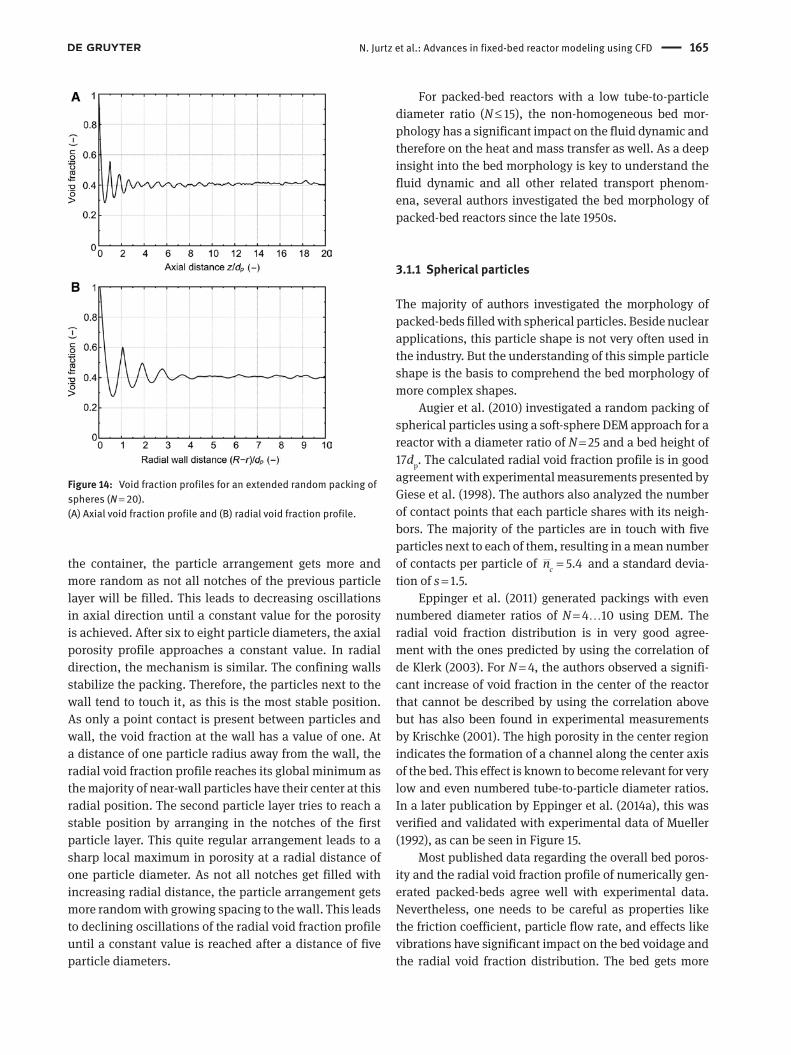
N. Jurtz et al.: Advances in fixed-bed reactor modeling using CFD 165
the container, the particle arrangement gets more and more random as not all notches of the previous particle layer will be filled. This leads to decreasing oscillations in axial direction until a constant value for the porosity is achieved. After six to eight particle diameters, the axial porosity profile approaches a constant value. In radial direction, the mechanism is similar. The confining walls stabilize the packing. Therefore, the particles next to the wall tend to touch it, as this is the most stable position. As only a point contact is present between particles and wall, the void fraction at the wall has a value of one. At a distance of one particle radius away from the wall, the radial void fraction profile reaches its global minimum as the majority of near-wall particles have their center at this radial position. The second particle layer tries to reach a stable position by arranging in the notches of the first particle layer. This quite regular arrangement leads to a sharp local maximum in porosity at a radial distance of one particle diameter. As not all notches get filled with increasing radial distance, the particle arrangement gets more random with growing spacing to the wall. This leads to declining oscillations of the radial void fraction profile until a constant value is reached after a distance of five particle diameters.
For packed-bed reactors with a low tube-to-particle diameter ratio (N ≤ 15), the non-homogeneous bed mor-phology has a significant impact on the fluid dynamic and therefore on the heat and mass transfer as well. As a deep insight into the bed morphology is key to understand the fluid dynamic and all other related transport phenom-ena, several authors investigated the bed morphology of packed-bed reactors since the late 1950s.
3.1.1 Spherical particles
The majority of authors investigated the morphology of packed-beds filled with spherical particles. Beside nuclear applications, this particle shape is not very often used in the industry. But the understanding of this simple particle shape is the basis to comprehend the bed morphology of more complex shapes.
Augier et al. (2010) investigated a random packing of spherical particles using a soft-sphere DEM approach for a reactor with a diameter ratio of N = 25 and a bed height of 17dp. The calculated radial void fraction profile is in good agreement with experimental measurements presented by Giese et al. (1998). The authors also analyzed the number of contact points that each particle shares with its neigh-bors. The majority of the particles are in touch with five particles next to each of them, resulting in a mean number of contacts per particle of 5.4cn = and a standard devia-tion of s = 1.5.
Eppinger et al. (2011) generated packings with even numbered diameter ratios of N = 4…10 using DEM. The radial void fraction distribution is in very good agree-ment with the ones predicted by using the correlation of de Klerk (2003). For N = 4, the authors observed a signifi-cant increase of void fraction in the center of the reactor that cannot be described by using the correlation above but has also been found in experimental measurements by Krischke (2001). The high porosity in the center region indicates the formation of a channel along the center axis of the bed. This effect is known to become relevant for very low and even numbered tube-to-particle diameter ratios. In a later publication by Eppinger et al. (2014a), this was verified and validated with experimental data of Mueller (1992), as can be seen in Figure 15.
Most published data regarding the overall bed poros-ity and the radial void fraction profile of numerically gen-erated packed-beds agree well with experimental data. Nevertheless, one needs to be careful as properties like the friction coefficient, particle flow rate, and effects like vibrations have significant impact on the bed voidage and the radial void fraction distribution. The bed gets more
Figure 14: Void fraction profiles for an extended random packing of spheres (N = 20).(A) Axial void fraction profile and (B) radial void fraction profile.

166 N. Jurtz et al.: Advances in fixed-bed reactor modeling using CFD
dense with decreasing friction coefficients and increasing particle flow rate and due to vibrational effects.
3.1.2 Cylindrical particles
Cylindrical particles are often found in the chemical industry as catalyst support as they can be very easily manufactured using extruders. Compared to spherical particles, the bed morphology is determined not only by the position of the particles but also by their orientation.
Xu et al. (2006) were the first who numerically analyzed packings of cylindrical particles with a par-ticle diameter of 5.4 mm, a particle length of 3.8 mm in a column with a diameter of 43.3 mm using DEM and a Monte Carlo method. They statistically analyzed the bed morphology and compared the results with experimental measurements using NMR. They found that DEM is able to generate packings that are comparable to experimen-tally generated beds in terms of integral indicators like packing density and mean empty space between solids in the packing. The usability of DEM for the generation of packings with cylindrical particles was confirmed and extended by Eppinger et al. (2014a). Regarding the global void fraction, they found very good agreement with corre-lations by Dixon (1988) and Foumeny and Roshani (1991). The radial void fraction distribution matched the experi-mental data of Giese et al. (1998) and Roshani (1990), as shown in Figure 16.
Caulkin et al. (2009b) and Boccardo et al. (2015) ana-lyzed the orientation of the particles. Their findings indi-cate that the highest number of particles (around 20%) tends to be horizontally aligned with respect to their
rotation axis. Furthermore, the results of Caulkin et al. (2009b) show that the axial void fraction profile flattens out into a constant value after a distance of four particle diameters from the bottom while the radial profile reaches a constant value about six particle diameters away from the wall. If the bed gets tapped after the filling process, the packing gets more dense. As a result, the oscillating radial void fraction profile gets more pronounced regarding its local minima and maxima and reaches a constant voidage after 10 particle diameters.
3.1.3 Complex particle shapes
Beside spherical and cylindrical particles, even more complex shapes are used in the industry, especially as catalyst support. The goal is to increase the active surface of catalyst particles and to achieve a more homogeneous plug-flow-like velocity field.
In several publications, Caulkin et al. (2008, 2009b, 2012) investigated the bed morphology of different complex particle shapes like hollow cylinders, multihole cylinders, Pall rings, and Trilobes.
Caulkin et al. (2009b) explored the impact of the inner diameter of hollow cylinders on the radial void fraction distribution and compared their results against a packing of four-hole cylinders. The results are depicted in Figure 17. They found that in case of hollow cylinders, the radial porosity profile strongly depends on the ratio of inner to outer particle diameter. For a small inner diameter, the radial void fraction distribution is comparable to that of cylindrical particles. Only the local minimum and maximum porosity values are more pronounced, and due
Figure 15: Comparison of the radial porosity profile for a monodis-perse packed bed with N = 3.96.Experimental data are taken from Mueller (1992). Reprinted with permission from Eppinger et al. (2014a).
Figure 16: Comparison of the radial porosity distribution of a packed bed with cylindrical particles.Reprinted with permission from Eppinger et al. (2014a).

N. Jurtz et al.: Advances in fixed-bed reactor modeling using CFD 167
to the inner void of the particles, the local minima show some dents. If the inner diameter gets further increased, the small dents develop to pronounced additional local porosity maxima in the near-wall region (within 2dp dis-tance from the wall). Caulkin et al. (2008) found that those maxima get more pronounced if the bed gets tapped after the filling process. After a distance of approximately 2dp away from the wall, an almost homogenous porosity distri-bution can be observed if the inner diameter chosen is not too small. Of course, the mean bed void fraction increases if the inner voidage of the particles is raised. The results
were confirmed by Eppinger et al. (2014b), who also found pronounced additional local porosity maxima within a distance of two particle layers away from the wall followed by a nearly homogeneous void fraction distribution.
The comparison of the radial void fraction profiles of hollow and multihole cylinders with equal inner voidage (HC3 and HC5) shows quite similar results. The multi-hole cylinders show less pronounced additional voidage maxima. This is due to the spreading of the inner void of a particle. In combination with the different orientation possibilities, this leads to an additional statistical smear-ing effect. Furthermore, the results indicate that multihole cylinders show an increased overall bed voidage. As the inner void volume is equal for both particle shapes, the-oretically, the overall bed voidage should not change as long as the particle properties, the boundary conditions, or the particle dynamic during the filling process is not significantly changed.
Packings of Pall rings have been investigated by Caulkin et al. (2008). They found that packed beds of Pall rings show an unusual radial void fraction distribution within the near-wall region. Multiple local minima and maxima can be observed in that area. After a distance of about 3dp away from the wall, the radial void fraction profile gets constant.
Caulkin et al. (2012) found that Trilobes (hp/dp = 4.6) show a proximate constant radial void fraction distribu-tion after a distance of 1.25dp away from the wall. The porosity profile shows a local maximum of ε = 0.506 at a distance of 0.82dp followed by a global minimum of ε = 0.468 at 0.5dp followed by an increasing porosity towards the confining wall. It needs to be stated that the results for the near-wall region are at least questionable as the simulated void fraction and the experimental data as well do not reach a value of ε = 1 directly at the wall.
3.2 Fluid dynamics
For fixed-bed reactors with a low N, the heterogeneous bed morphology strongly affects the fluid dynamics of the system. Local effects – especially in the near wall region – have significant impact on the characterization of the overall system. Therefore, common simplifications like a plug-flow-like radial velocity profile valid for extended packed-beds do not hold true for low diameter ratios N.
3.2.1 Pressure drop
One of the most important and crucial parameters for the design of a fixed-bed reactor is the pressure drop. It
Figure 17: Investigated particle shapes and comparison of measured (symbol), DigiPac (dashed line), and DigiCGP (solid line) predicted local voidage data for conventional packed beds of hollow cylinders.Reprinted with permission from Caulkin et al. (2009b). Copyright (2009) Elsevier.
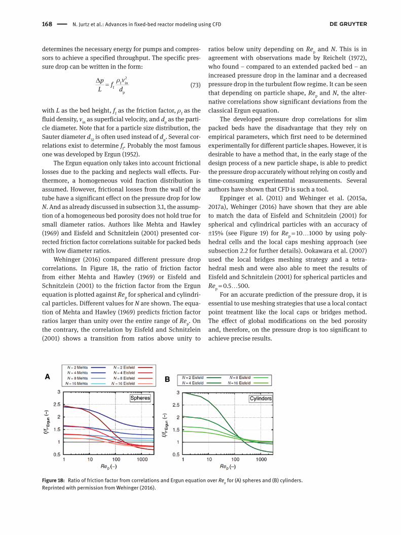
168 N. Jurtz et al.: Advances in fixed-bed reactor modeling using CFD
determines the necessary energy for pumps and compres-sors to achieve a specified throughput. The specific pres-sure drop can be written in the form:
2f in
fp
vp fL d
ρ∆ =
(73)
with L as the bed height, ff as the friction factor, ρf as the fluid density, vin as superficial velocity, and dp as the parti-cle diameter. Note that for a particle size distribution, the Sauter diameter d32 is often used instead of dp. Several cor-relations exist to determine ff. Probably the most famous one was developed by Ergun (1952).
The Ergun equation only takes into account frictional losses due to the packing and neglects wall effects. Fur-thermore, a homogeneous void fraction distribution is assumed. However, frictional losses from the wall of the tube have a significant effect on the pressure drop for low N. And as already discussed in subsection 3.1, the assump-tion of a homogeneous bed porosity does not hold true for small diameter ratios. Authors like Mehta and Hawley (1969) and Eisfeld and Schnitzlein (2001) presented cor-rected friction factor correlations suitable for packed beds with low diameter ratios.
Wehinger (2016) compared different pressure drop correlations. In Figure 18, the ratio of friction factor from either Mehta and Hawley (1969) or Eisfeld and Schnitzlein (2001) to the friction factor from the Ergun equation is plotted against Rep for spherical and cylindri-cal particles. Different values for N are shown. The equa-tion of Mehta and Hawley (1969) predicts friction factor ratios larger than unity over the entire range of Rep. On the contrary, the correlation by Eisfeld and Schnitzlein (2001) shows a transition from ratios above unity to
ratios below unity depending on Rep and N. This is in agreement with observations made by Reichelt (1972), who found – compared to an extended packed bed – an increased pressure drop in the laminar and a decreased pressure drop in the turbulent flow regime. It can be seen that depending on particle shape, Rep and N, the alter-native correlations show significant deviations from the classical Ergun equation.
The developed pressure drop correlations for slim packed beds have the disadvantage that they rely on empirical parameters, which first need to be determined experimentally for different particle shapes. However, it is desirable to have a method that, in the early stage of the design process of a new particle shape, is able to predict the pressure drop accurately without relying on costly and time-consuming experimental measurements. Several authors have shown that CFD is such a tool.
Eppinger et al. (2011) and Wehinger et al. (2015a, 2017a), Wehinger (2016) have shown that they are able to match the data of Eisfeld and Schnitzlein (2001) for spherical and cylindrical particles with an accuracy of ±15% (see Figure 19) for Rep = 10…1000 by using poly-hedral cells and the local caps meshing approach (see subsection 2.2 for further details). Ookawara et al. (2007) used the local bridges meshing strategy and a tetra-hedral mesh and were also able to meet the results of Eisfeld and Schnitzlein (2001) for spherical particles and Rep = 0.5…500.
For an accurate prediction of the pressure drop, it is essential to use meshing strategies that use a local contact point treatment like the local caps or bridges method. The effect of global modifications on the bed porosity and, therefore, on the pressure drop is too significant to achieve precise results.
Figure 18: Ratio of friction factor from correlations and Ergun equation over Rep for (A) spheres and (B) cylinders.Reprinted with permission from Wehinger (2016).

N. Jurtz et al.: Advances in fixed-bed reactor modeling using CFD 169
3.2.2 Velocity field
The complex interplay between bed morphology and local velocity field has been investigated by several authors
during the last decade. Although the velocity field shows strong local differences, it was found that the radial dis-tribution of the axially averaged velocity field can be cor-related to the radial void fraction profile.
Eppinger et al. (2011) investigated the flow field of packed beds made of spherical particles for several diameter ratios (N = 5…8) and Reynolds numbers (Rep = 1…1000). They found that the maximum value of the axial velocity can exceed the superficial inlet velocity by a factor of 11. Those maximum velocities are found in the interstitial voids, while the areas in the vicinity of the contact points are character-ized by stagnant zones of very low velocity. Furthermore, a strong wake can be seen at the end of the fixed bed.
Figure 20 shows the radial distribution of the void fraction and the axially and circumferentially averaged normalized axial velocity for different N and Rep. A strong correlation between the velocity and void fraction profile can be found. Due to the wall effect, the highest velocity exists in the proximity of the wall. It exceeds the theoreti-cal value of the mean interstitial velocity by a factor of three, almost independent of N and Rep. With increasing distance from the wall, the velocity profiles show a declin-ing oscillating behavior, whereas the local minima and
Figure 19: Pressure drop over the fixed-bed: the data cloud on the left-hand side represent different D/dp ratios at Rep = 1, the central one at Rep = 100, and the right-hand side at Rep = 1000.Reprinted with permission from Eppinger et al. (2011). Copyright (2011) Elsevier.
Figure 20: Circumferential-averaged axial velocity profile calculated from velocity values within the bed for (A) Rep = 1, (B) Rep = 100, and (C) Rep = 1000 and different diameter ratios.Reprinted with permission from Eppinger et al. (2011). Copyright (2011) Elsevier.

170 N. Jurtz et al.: Advances in fixed-bed reactor modeling using CFD
maxima correspond with the oscillations of the radial void fraction distribution.
The impact of the particle shape on the velocity field was investigated by Wehinger (2016). He compared spheres, cylinders, and one-hole cylinders and found that spherical and cylindrical particles show a quite similar radial profile of the averaged velocity, as can be seen in Figure 21. The numerical results agree well with the experimental data of Giese et al. (1998) and show a maximum velocity of approximately two times the local axially and circumferentially averaged interstitial veloc-ity close to the wall. For one-hole cylinders, the bypass-ing effect near the wall is significantly reduced by showing a maximum velocity of 1.7 times the local inter-stitial velocity. This is caused by additional inner parti-cle voids that do not only reduce the near wall bypassing effect but also lead to an overall more homogeneous velocity field that shows a less oscillating behavior. This is in accordance with simulation results of Caulkin et al. (2008, 2012) and data of Giese et al. (1998) and Bey and Eigenberger (1997). For more complex particle shapes like Trilobes, Caulkin et al. (2012) found an almost plug-flow-like velocity profile.
The impact of the inner particle voids on the local flow field was examined by Dixon et al. (2012a). Based on a segment model, they compared the flow field characteristic of cylindrical particles containing a dif-ferent number of holes. They found that additional holes reduce regions of stagnant and swirling flow behind the particle. Whether the holes are effectively used depends on hole diameter and particle orienta-tion. The more the particles are oriented perpendicular to the flow, the less effective are the inner voids. This indicates the importance of knowledge of the particle orientation as additional parameter to describe the bed morphology.
3.2.3 Mixing characteristics
The problem with axial and circumferential averaging the velocity field is that all information regarding possible backflow and stagnant zones is lost. But the knowledge about these effects is essential, as it can affect safety and efficiency in a negative manner.
Eppinger et al. (2011) investigated stagnant zones and backflow regions for packings of spherical particles, as shown in Figure 22. They found that the frequency of these phenomena increases for higher Reynolds numbers. For Rep = 1000, around 13% of the packed bed is characterized by either stagnant zones or backflow, while in the laminar flow regime, only 1% of the volume is affected.
To quantify the effect of back mixing and stagnant zones, Wehinger (2016) investigated the residence time distribution of packed beds by conducting virtual tracer experiments using a particle tracking method. Figure 23 shows the residence time distribution functions for spheres, cylinders, and one-hole cylinders as a function of residence time normalized by the hydraulic residence time / .t L u
ε= The modal value of a distribution is the
value that appears most often. All of the governed nor-malized modes show a residence time that is significantly lower than one, which indicates channeling effects. Fur-thermore, multiple decaying peaks occur, which represent strong internal recirculations and channeling. All curves show long tailing, which is a strong indicator for stagnant backwaters. The large variances reflect the large deviation from plug flow behavior. The one-hole cylinder packing shows the most plug-flow-like characteristic compared to the other particle shapes. It has the largest modal value and the narrowest distribution function with the least tailing.
Based on the radial distribution function, the axial dispersion coefficient Dax can be determined, as done by
Figure 21: Specific velocity (vz · ε(r))/(vin) for experiments from Giese et al. (1998) and CFD simulations for packed bed of spheres (left) and cylinders (right).Reprinted with permission from Wehinger (2016)].

N. Jurtz et al.: Advances in fixed-bed reactor modeling using CFD 171
Freund et al. (2003, 2005) and Atmakidis and Kenig (2014). The dispersion coefficient, respectively, the Péclet number Pe =(vin · dp)/Dax, is not only a useful parameter to qualita-tively characterize the system within the range of the plug flow reactor (Pe→ ∞) and the ideal stirring vessel (Pe→0) but also needed as input parameter for less sophisticated but faster modeling approaches like the axial dispersion model, which is widely used in the industry to calculate
the species propagation in fixed beds. Unfortunately, cor-relations for the axial dispersion coefficient are most often only known for simple particle shapes in extended fixed beds. Likely, it is a useful option to determine the axial dispersion coefficient based on particle-resolved CFD sim-ulations, which can later be used in simplified models. By now, published CFD studies dedicated to dispersion in fixed-bed reactors are small in number and only limited to Rep < 300, which is below most industrial applications.
3.3 Heat transfer
An adequate description of both the reaction kinetics and the transport processes of heat and mass is required to design a (catalytic) fixed-bed reactor. In Figure 24, dif-ferent mechanisms for heat transfer are illustrated sche-matically in a fixed bed of spheres. Depending on process parameters like flow rate, temperature, and fluid proper-ties, certain mechanisms can dominate.
The radial transport process of heat is of paramount interest, as it is the direction of heating or cooling the reactor. Especially, for low N fixed beds, an accurate description of the radial transport is difficult. Dixon (2012)
Figure 22: Regions with zero or negative velocities for (A) Rep = 1, (B) Rep = 100, and (C) Rep = 1000.Reprinted with permission from Eppinger et al. (2011). Copyright (2011) Elsevier.
Figure 23: Residence time distribution function for different packings.Reprinted with permission from Wehinger (2016).

172 N. Jurtz et al.: Advances in fixed-bed reactor modeling using CFD
comprehensively reviewed radial heat-transfer models in fixed-bed catalytic reactors. The most common formula-tion is the kr − hw model, which is based on the classical pseudo-homogeneous 2D (radial and axial direction) axially dispersed plug flow (ADPF) model. In Europe, this model is called “αw” model. The boundary condition at the wall (r = R) yields:
r w w( ),Tk h T T
r∂− = −∂
(74)
where kr is the constant effective radial thermal conductiv-ity, T is temperature, Tw is wall temperature, r is the radial coordinate, and hw represents the wall heat transfer coeffi-cient. This model shows a temperature “jump” at the wall, due to hw Dixon (2012). In most cases, hw is expressed by the wall Nusselt number Nuw:
w w p f/ ,Nu h d k= (75)
where kf is the thermal conductivity of the fluid.Several formulations for Nuw are available in litera-
ture. However, the most recommended form is the mecha-nistic model. Nuw represents the sum of the contribution of the decreased solid-phase conduction Nuw,0 and the contribution of the decreased lateral convective heat transfer near the wall a · PrbRec. Martin and Nilles (1993) formulated Nuw as follows:
1/3 3/4w w,0 p0.19 ,Nu Nu Pr Re= + (76)
where the Prandtl number is defined as Pr = cpμ/k. Dixon (2012) recommends to calculate Nuw,0 with:
0
w,051.3 ,r
f
kNu
N k
= + (77)
with N = dp/D, and 0rk is the thermal conductivity of the
bed, which can be calculated by the Zehner-Schlünder equation, see, e.g. Dixon et al. (2013a). In literature, there are more formulations found especially for the decreased lateral convective heat transfer near the wall. A critical review on different models and recommenda-tions was given by Dixon (2012). The authors conclude that the kr − hw model shows likely an error range of 20–30%. Under these circumstances, particle-resolved CFD simulations of packed beds can shed light on the radial heat transfer, especially for low N beds. Magnico (2009) performed transient DNS of heat transfer in a bed with 326 and 620 particles, respectively. The author found reasonable agreement for hw with the correlation of Martin and Nilles (1993). Full-bed CFD simulations with an accompanying experimental measurement are the exception. Dixon et al. (2012b) simulated a full bed of 1000 and 1250 spheres including heat transfer through the particles. Radial temperatures were measured at the outlet of the packed bed. The agreement between experi-ment and simulations is reasonable. The authors tried to examine steeper gradients inside the bed by varying the bed length.
More recently, axial heat transfer by particle-resolved 3D CFD simulations was validated with axial experimen-tal data by Wehinger et al. (2016b). For the experiments, a reactor setup was used, see Figure 25, which measures the axial temperature and, if present, the axial concentration in situ and operando with a capillary technique. Through a small orifice, a small amount of gas is constantly sucked into the capillary giving the axial gas-phase temperature. Two sets of experiments were conducted without chemi-cal reactions, see Figure 26, and compared to simulated values. In the detailed simulations, the capillary was
Figure 24: Different mechanisms for heat transfer in a fixed-bed reactor.Reprinted with permission from Wehinger (2016).

N. Jurtz et al.: Advances in fixed-bed reactor modeling using CFD 173
taken into account around which the spheres settled. For the simulations, the values of the adiabatic capillary wall were used, representing the axial corresponding gas-phase temperature. As can be seen, the CFD simula-tions show an excellent agreement with the experiments. This case highlights that the local transport of heat inside a fixed-bed reactor can be reproduced with high accu-racy over the entire length by the particle-resolved CFD approach.
Dong et al. (2017) investigated radial heat transfer by profile measurement techniques and 3D CFD simula-tions. Heat transfer in a small D fixed-bed reactor packed with spheres and one-hole cylinders was studied at dif-ferent flow rates (60 < Rep < 100) and packing heights. In general, good agreement between experiment and simu-lation was achieved. However, in the simulations, the influence of the capillary inserted in the packed bed was not taken into account. In future studies, the quantitative effect of the capillary technique on the observed heat and mass transfer should be studied. Especially, industrial rel-evant reactor conditions (Rep > 1000 and temperatures up to 1300 K) are of interest.
As pointed out in subsection 2.2, particle-particle and particle-wall contacts can lead to severe convergence prob-lems. Hence, a modification of these contacts is required for most of the CFD simulations. Recently, Wehinger et al. (2017a) studied the effects of local contact modifications (i.e. caps and bridges method for line and area contacts,
and caps and united method for overlaps resulting from composite DEM particles) towards heat transfer in a bed of cylinders. Besides heat transfer, pressure drop and local velocity are investigated. The study shows that with increasing Rep, the modification of particle-wall contacts is becoming more important, see Figure 27. As convective heat transfer is becoming dominant, contact modifica-tions in the bulk of the bed are becoming less important. Promising results in terms of heat-transfer predictions can be achieved with the local caps method. However, for high flow rates, convective heat transfer in contact regions is overestimated. The alternative bridges method predicts well pressure drop and heat transfer. Nonethe-less, the choice of the thermal conductivity of these artifi-cially inserted bridges is still a topic to discuss much more thoroughly.
Gas flow in
Temperature probe:thermocouple orpyrometer fiber
H =
25
mm
to MS or GC for gas analysis
Position by steppermotors in µm resolution
Alumina foamfront heat shield
Catalytic spheresd = 1 mm
Quartz tube
Sampling orificeds = 25 µm
Gas flow out
Quartz capillarydc = 0.7 mm
D = 18 mm
Figure 25: Profile reactor set-up with spherical particles.Reprinted with permission from Wehinger et al. (2016b). Copyright (2016) John Wiley and Sons.
–10
400
550
600
650
700
750
800
450
500
550
600
Tem
pera
ture
(°C
)T
empe
ratu
re (
°C)
650
700FHS Fixed bed
FHS Fixed bed
A
B
–5 0 5 10
Axial coordinate (mm)
Experiment3D sim.
Experiment3D sim.
15 20 25
–10 –5 0 5 10
Axial coordinate (mm)
15 20 25
Figure 26: Measured and simulated axial temperature profile.Front heat shield (FHS). (A) Twall = 635°C and =in 2500 ml/min.V (B) Twall = 735°C and =in 1500 ml/min.V Reprinted with permis-sion from Wehinger et al. (2016b). Copyright (2016) John Wiley and Sons.

174 N. Jurtz et al.: Advances in fixed-bed reactor modeling using CFD
3.4 Mass transfer and heterogeneous reacting systems
Dixon et al. (2006) reviewed comprehensively the contri-butions of particle-resolved CFD simulations incorporat-ing mass transfer and reacting systems until 2006. Only work after that date is reviewed here. In the section, we particularly focus on reactor geometry, type of mesh, flow conditions, applied kinetics, and coupled transport phenomena.
3.4.1 Mass transfer and homogeneous reactions
Guardo et al. (2007) investigated particle-to-fluid heat and mass transfer in supercritical conditions by means of particle-resolved CFD simulations. This work is a con-tinuation of earlier contributions where heat transfer and the influence of turbulence were studied with detailed CFD in a randomly packed bed (Guardo et al. 2004, 2005). The authors used a bed consisting of 44 spheres with N = 3.923, which is the same arrangement as in the pre-vious studies. Increasing the spheres by 0.5% avoided contact point problems, i.e. the global overlaps method. The CFD code Fluent was used to construct the tetrahedral mesh and solve the Navier-Stokes equations including the
Spalart-Allmaras turbulence model. Constant tempera-ture and C7H8 concentration on the surface were taken into account to evaluate transport coefficients for heat and mass (kc,h). The CFD results were in good agreement with correlations from literature for Rep > 10. However, a strong dependency on the mesh was noticed.
Mousazadeh et al. (2013) presented a 2D model of a randomly packed fixed-bed reactor of spheres with a length of L = 60 · dp and a width of D = 10 · dp. The arrange-ment of the spheres were conducted manually. An unstruc-tured triangular mesh in the gas-phase bulk and 15 layers of quadrilateral cells were used. Three different meshes were tested with a total number of cells ranging from 1.8 × 10⁶ to 2.7 × 10⁶. Intraparticle heat and mass trans-port were not considered. Laminar flow with Reynolds number of 3.5 based on particle diameter and interstitial velocity was studied using the CFD software Fluent. The gas-phase reaction between ethylene and oxygen to ethyl-ene oxide was considered by using a one-step Arrhenius type kinetic. The axial development of species concentra-tion and temperature were in agreement with a plug flow model.
3.4.2 Heterogeneous catalytic reactors
Fixed-bed reactors are commonly used for gas-solid cata-lyzed reactions, such as ammonia synthesis, syngas pro-duction (see Figure 28), hydro-cracking, etc. (Eigenberger 2008). As a consequence, the inclusion of surface reactions into the modeling of fixed-bed reactors is highly relevant
1515
20
25
30
35
40
45
Nu w
(–)
50
55
20
Rep = 191
Rep = 382
Rep = 763
United w/wall contactUnitedCaps
Bridges w/wall contact k = 0.07
Bridges w/wall contact k = 0.5
Bridges k = 0.5
Bridges k = 0.07
+10%
–10%
25Nuw correlation (–)
30 35
Nuw correl.
Figure 27: Parity plot of wall Nusselt number from CFD simulations of different contact-area modifications over Nuw from correlation of Martin and Nilles (1993).Reprinted with permission from Wehinger et al. (2017a). Copyright (2017) American Chemical Society.
Figure 28: Typical arrangement of reformer tubes filled with catalytic particles.Reprinted with permission from Wehinger et al. (2017b). Copyright (2017) Elsevier.

N. Jurtz et al.: Advances in fixed-bed reactor modeling using CFD 175
for industrial applications. Industrial catalysts have to meet economic requirements, i.e. space-time yield, activ-ity, selectivity, and costs. In general, three different struc-tural types of solid catalysts are applied, which depend on the chemical reactions to be catalyzed (Gallei et al. 2008, Deutschmann et al. 2009):1. Unsupported (bulk) catalysts consists completely of
the catalyst material. Examples are metal oxides, sim-ple binary oxides, complex multicomponent oxides, carbons, etc.
2. Supported catalysts consists of support on which the catalyst material is dispersed. The support, which can be also catalytic active, is sponge-like and character-ized by a high porosity and large internal surface. Most commonly binary oxides, like transitional alu-mina, αAl2O3, SiO2, etc., are applied. Typical arrange-ments are shown in Figure 29.
3. Coated catalysts are indicated by a thin layer (≈100 μm) or shell of active material allocated across an inert structured surface. Examples are egg-shell catalyst, monolithic honeycombs, structure packings, foams, catalytic filters, etc.
This section is divided into CFD models that only take into account reactions on the pellet surface and such models that include reactions inside the pellets, i.e. intraparticle reactions.
3.4.2.1 Surface chemistry onlyModels that only take into account surface chemistry while intraparticle mass transport is neglected are oriented towards egg-shell catalyst configurations, see Figure 29B.
A study of endothermic SRM by Kuroki et al. (2009) considered 349 spheres of 1.75-mm diameter in an annular bed of 25-mm length with inner diameter of 2 mm and outer diameter of 10 mm. DEM simulations were used to generate random packing. The so-called bridge method was utilized to prevent convergence problems close to contact points. Finally, a tetrahedral volume mesh was
created with refinement close to surfaces, which was developed in an earlier study (Kuroki et al. 2007). Intrapar-ticle heat and mass transport was not considered. On the catalyst surface, a three-step reaction mechanism of SRM developed by Xu and Froment (1989) was implemented. The rate constants were re-defined to meet the definition of a molar flux through the particle surface, i.e. in units of mol m−2 s−1. Subroutines evaluating the reaction rate were included into the CFD software Fluent. The authors studied SRM with varying wall heat flux and Rep number of 300. The outlet species concentrations were compared to experimental data from Hoang et al. (2005) and agreed remarkably well, especially when methane was nearly consumed. However, transport properties inside the bed were not validated.
Li et al. (2013) modeled the endothermic dehydro-genation of isopropanol in a 2D Sierpinski carpet fractal structure representing a porous medium of the fixed bed. A Lattice-Boltzmann code was used in which a one-step Arrhenius type kinetic was implemented. Intraparticle phenomena were not incorporated. Laminar flow at 450 K was studied without any comparison to experimental data.
A catalytic fixed bed of spheres with varying diameters (N = 2.3, 3.2, 5.3) and height of H/dp = 7.2, 10, and 16.6 was modeled and spatially resolved by Zhou et al. (2013). Acetone hydrogenation was considered on the adiabatic surfaces with a one-step LHHW reaction-kinetic model. A non-specified structural mesh was used in Fluent to calculate this problem. The effect of different velocities at laminar flow towards reactor performance and pres-sure drop was tested. The authors concluded that smaller diameter pellets are advantageous for acetone hydrogena-tion, but large pressure drop is the downside.
Particle-resolved CFD was used in a couple of studies to investigate details of coal combusters and gasifiers (Safronov et al. 2014, Richter et al. 2015, Sahu et al. 2016). The studies ranged from reacting single spheres to 2D arrays of spheres and finally to a porous particle made up of an agglomeration of 185 monodisperse spherical particles. Semi-global heterogeneous and homogeneous reactions following Arrhenius formulations were applied. Laminar flow, ambient pressure, surface radiation, and temperatures up to 3000 K were studied. Intraparticle heat and mass transport were not taken into account. ANSYS Fluent was used to generate the prismatic or unstructured mesh ranging from several thousands cells in case of the 2D domain to several million cells for the porous particle case. Interactions of local kinetic and local transport phe-nomena were evaluated using the Thiele modulus, effec-tiveness factor, and Damköhler numbers.
Figure 29: Typical catalyst distribution inside a support.(A) Uniform, (B) egg shell, (C) egg white and (D) egg yolk. Adapted with permission from Lekhal et al. (2001). Copyright (2001) Elsevier.

176 N. Jurtz et al.: Advances in fixed-bed reactor modeling using CFD
Microkinetics describe heterogeneous catalysis in a very fundamental way. Maestri and Cuoci (2013b) coupled full 3D CFD with microkinetics description of H2 fuel-rich combustion on Rh. A novel solver, called catalyticFOAM (Maestri and Cuoci 2013a), was proposed being based on the operating-splitter technique and incorporated into the software environment OpenFOAM. As a show case, the new solver is tested on two non-touching adiabatic spheres with a diameter of 3 mm in a tube of 5 mm in diameter. A 2D axisymmetric mesh was used consisting of 4000 cells of rectangular and triangular shapes. Full consumption of oxygen was reached in the wake of the spheres leading also to the adiabatic temperature of the reacting mixture. By using microkinetics, the most abundant reaction interme-diate (MARI) can be specified, which is H* in this case. The authors also presented an isothermal hydrogen fuel-rich combustion on Rh in a one-hole cylinder ring arrangement. The 3D model consisted of a unstructured hexahedral mesh of approximately 250,000 cells. Laminar flow at 473 K was considered. Surface reactivity and concentration pro-files showed strong gradients, mainly due to the random arrangement of the bed. Again the microkinetic model could detect adsorbed species on the pellet surface. H* was the MARI, which covered approximately 80% of the entire pellet surface, see Figure 30. As can be seen in this figure, the applied meshing algorithm was not able to produce a smooth surface of the pellets. Thin and sharp cells are apparent at the edges of the one-hole cylinders. Still, this work represents the initial distribution of coupling micro-kinetics of surface chemistry with detailed fixed-bed CFD.
Wehinger et al. (2015a) used the software STAR-CCM+ to couple the microkinetics description of dry reforming of methane (DRM) on Rh with full 3D in a bed of 113 spheres. The bed measured H/dp = 10 and N = 3.96. The random bed generation was realized with DEM simulations. Locally
flattening of particles, i.e. the caps method, was applied to avoid bad cells. The locally refined polyhedral mesh consisted of approximately 3–11 million cells depending on the inlet velocity. Two prism layers close to the cata-lytic wall were generated to resolve appearing gradients. The prism layer thickness was approximated based on the boundary layer thickness in the stagnation point of a sphere (Dhole et al. 2006). Figure 31 shows the gas-phase mesh only with prism layers close to surfaces and polyhedral cells elsewhere. Intraparticle heat transfer was considered. The microkinetics description of the DRM was implemented as a species boundary condition on the surface of the spheres. Laminar and turbulent flow at constant inlet concentrations was studied resulting in different radial and axial properties. Although the compu-tational time was very high, with such detailed CFD simu-lations, the interactions between local kinetics and local transport phenomena could be quantified, supporting fundamental understanding of fixed-bed reactors. This modeling approach was later extended towards fixed beds of spheres, cylinders, and one-hole cylinders (Wehinger et al. 2015b). The effect of pellet shapes towards the per-formance of a fixed-bed reactor was demonstrated with particle-resolved CFD for DRM on Rh. Besides evaluating axial, radial, and exit transport properties, the interpreta-tion was assisted by residence-time distribution analysis. As can be seen in Figure 32, the local temperature influ-ences the local mole fractions and vice versa. Figure 33 shows local variations of surface adsorbed carbon (C*) for different pellet shapes of a DRM showcase. For this par-ticular parameter set, the bed of cylinders showed the best performance regarding conversion and yield.
In a more recent study, Wehinger et al. (2016a) vali-dated particle-resolved CFD simulations of DRM on nickel in a bed of spheres with experimental data. The
Figure 30: Surface adsorbed hydrogen (H*) on an isothermal bed of one-hole cylinders.Reprinted with permission from Maestri and Cuoci (2013b). Copyright (2013) Elsevier.
Figure 31: Mesh detail of CFD simulation.With permission from Wehinger (2016).

N. Jurtz et al.: Advances in fixed-bed reactor modeling using CFD 177
1-mm-diameter spheres had a thin washcoat (<10 μm) in which the Ni catalyst was dispersed. In the profile reactor of the Horn group from TU Hamburg (Horn et al. 2010), axial temperature and species concentration profiles were measured. The bed was H/dp = 25 high and N = 18 in dia-meter. With DEM simulations, the randomly packed bed of spheres including the measure capillary was generated. A comprehensive microkinetics from literature (Delgado et al. 2015) consisting of 52 irreversible reactions was used. Only a small slice of the entire bed was simulated due to the large amount of spheres in the bed. The mesh generation was conducted by the suggestions of the pre-vious studies. Whereas heat transfer simulations without
reaction were in excellent agreement with the experi-ments, DRM could not be reproduced entirely. The main reason can be found in thermodynamic inconsistencies of the microkinetics for this set of experimental conditions. Inconsistencies in enthalpy led to a stronger decrease in the center of the bed, which had a great influence to the reactivity. Internal and external mass transport limita-tions were evaluated by using the Thiele modulus and the Damköhler number, respectively. As intraparticle limita-tions were moderate to small, the assumption of instan-taneous diffusion was justified. The profile reactor setup from the Horn group delivers axial data with which par-ticle-resolved CFD simulations can be validated in a very
Figure 32: Temperature and mole fraction of methane are shown on a cut through a bed of spheres, cylinder and one-hole cylinders.Mole fraction of methane (A–C) and temperature (D–E) on a plane cut through the fixed-bed for spheres, cylinders and one-hole cylinders.Reprinted with permission from Wehinger et al. (2015b). Copyright (2015) John Wiley and Sons.

178 N. Jurtz et al.: Advances in fixed-bed reactor modeling using CFD
precise manner. In the future, this excellent test reactor should be complemented with a radial capillary to detect the very important radial gradients in temperature and species concentration.
Another example of coupling microkinetics with par-ticle-resolved CFD simulations was presented by Bracconi et al. (2017). In a duct containing 25 spheres, the catalytic methane conversion to syngas on Rh was modeled. For the
Figure 33: Surface site fraction of adsorbed carbon C* and streamlines for (A) spheres, (B) cylinders, and (C) one-hole cylinders for the DRM.Reprinted with permission from Wehinger et al. (2015b). Copyright (2015) John Wiley and Sons.
N. Jurtz et al.: Advances in fixed-bed reactor modeling using CFD 179
generation of the random packing, the LIGGGHTS open source CFD-DEM code (Kloss et al. 2012) was used. The bridges method was utilized avoiding contact points. The hexahedral mesh was generated with snappyHexMesh by OpenFOAM accounting for approximately 460,000 cells. The transient simulations were conducted under isother-mal conditions and by assuming that the reaction occurs only at the surface of the catalytic spheres. The ISAT algo-rithm was applied for the calculation of the species source terms. The intention of this study was to demonstrate the reduction of calculation time, which was a factor 14 times faster than the direct integration of each time step.
3.4.2.2 Intraparticle mass transport and reactionsModels that account for intraparticle mass transport and reaction are oriented towards unsupported (bulk) cata-lyst configurations, uniformly supported catalysts, see Figure 29A, as well as the “egg white” and “egg yolk” configuration, i.e. Figure 29C and D. A common issue in modeling intraparticle mass transport and reactions is associated with the particle-fluid interface. The common porous media model used for particles has the serious deficiency that convective fluxes across that interface are present. This means that the no-slip condition at the par-ticle surface is violated. Hence, this method is not suitable to model intraparticle mass transport and reactions in fixed-bed reactors. Dixon et al. (2010) presented a novel approach that models the particles as a solid with no-slip condition at the surface. User-defined scalars are formu-lated in the fluid and solid region, whereas reactions are defined in the solid region. Under steady-state conditions, the transport of scalar φk can be written as follows (Dixon et al. 2010):
ρ φ Γ φ∇⋅ − ∇ =
( ) 0,k k kV (78)
where k = 1, 2,…, Nsp−1 is the number of species, ρ is the density,
V is the velocity, and Γk is the transport para-
meter. In the solid phase and under steady-state condi-tions, it reads:
( )kk k S
φΓ φ−∇⋅ ∇ = (79)
The equation accounts only for transport by diffu-sion and a source term
kS
φ generating species φk. In both regions, the equations are accompanied by the following:
sp
sp
1
11
N
N kk
φ φ−
=
= − ∑
(80)
Furthermore, the method accounts for separate dif-fusion, i.e. effective Fickian diffusivity inside the solid
particle and molecular and turbulent diffusivity in the fluid region. The method was tested against the porous medium model for a single sphere and further applied in a wall segment of spheres for SRM using a LHHW kinet-ics. Turbulence was accounted for using the SST k-ω model. The authors used Fluent for the mesh generation consisting of orthogonal prism cells close to the surfaces and hexahedral cells elsewhere. A total of approximately 1.8 million cells were used for the wall segment study. The spheres were shrunk by 0.5% to avoid bad cells in the contact points. Fluent was also used to solve the govern-ing equations. Figure 34 shows a comparison between the porous media model and the solid particle model high-lighting the effect of the no-slip condition.
This method was further applied in a series of studies by the Dixon group. Methane steam reforming and propane dehydrogenation were studied in a segment of cylindrical pellets by Taskin et al. (2010). Detailed pellet surface and intraparticle temperature, species, and reaction rate distri-butions were evaluated for a near-wall particle. Non-uniform and non-symmetric variations were detected for surface and intraparticle transport properties. Behnam et al. (2010) studied carbon deposition in propane dehydrogenation in a segment of cylinders. Later, SRM was modeled to predict tem-perature and species profiles under the experimental SRM reaction conditions (Behnam et al. 2012). Figure 35 shows CFD of temperature and different mass fraction results for a stack of non-spherical pellets of SRM. Dixon et al. (2012a) investigated reaction rates, conduction, and diffusion inside catalyst particles with one-, three-, four-, and six-holes for SRM. In addition, the external flow and temperature fields near the heated tube wall were evaluated. The work espe-cially highlighted the effects of the different pellet features towards overall performance. However, experimental valida-tion data were not considered.
More recent studies of the Dixon group investigated different techniques to reduce the calculation time and likewise retain the accuracy of the kinetic model for particle-resolved CFD simulations (Partopour and Dixon 2016a,b, 2017). Intraparticle transport and reaction were modeled with the solid particle method (Dixon et al. 2010). An illustrative example of temperature and species distribution in the gas phase and solid particle is shown in Figure 36 for a small bed of spheres in which ethyl-ene oxidizes. In one study, Partopour and Dixon (2016b) applied conventional reaction engineering approaches, i.e. rate-determining steps and quasi-equilibrium, to reduce a microkinetics model to a model with general rate expressions. Although the complexity was significantly reduced, deviations between the reduced and the original model occurred, especially where sharp species gradients

180 N. Jurtz et al.: Advances in fixed-bed reactor modeling using CFD
appeared. In another study, Partopour and Dixon (2016a) mapped reaction rates from a microkinetics model into quadratic multivariate splines. These splines were
imported into user-defined functions and were incorpo-rated into the CFD simulations. This study showed that although the complexity of the model was reduced, the
Figure 34: Comparison of temperature profiles for sphere and surrounding fluid, for porous and solid particle models for SRM.Re = 10,000. Reprinted with permission from Dixon et al. (2010). Copyright (2010) American Chemical Society.
Figure 35: CFD of temperature and different mass fraction results for a stack of non-spherical pellets of SRM. (A) Hydrogen mass fraction, (B) methane mass fraction and (C) temperature (K) at the surface of the active particles in the CFD simulation of SRM. Reprinted with permission from Behnam et al. (2012). Copyright (2012) Elsevier.

N. Jurtz et al.: Advances in fixed-bed reactor modeling using CFD 181
Figure 36: Solid spheres can be distinguished from the gas phase. Contour plots of (A) temperature (K), (B) oxygen mass fration, (C) ethyleneoxide mass fraction, and (D) reaction rate [kmol/(m3/s)] on cut through the bed. Reprinted with permission from Partopour and Dixon (2016b). Copyright (2016) American Chemical Society.
main features of the kinetic model were retained. Finally, Partopour and Dixon (2017) compared the spline method with simplified lumped rate expressions for ethylene oxi-dation in a fixed bed of 120 spheres (N = 5.04). This study highlights that steep gradients inside the catalytically active spheres are the reason for significant deviations between the reduced kinetic model and the spline method with full microkinetics. This series of studies shows that not only the time saving of a method but also the accuracy or loss of information is important.
Peng et al. (2016) simulated the acetone hydrogena-tion in a small bed of spheres (H/dp = 5 high and N = 0.5, 3) taking intraparticle heat and mass transport into account. DEM was used to generate the bed. Global shrinking of 0.5% of the spheres was conducted to avoid bad cells close to contact points. Fluent was used to generate a tetrahe-dral mesh, both in the gas phase and the solid phase. Pris-matic meshes were used close to surfaces to account for gradient discretization. The acetone hydrogenation was described with a main reaction and a principle second-ary reaction. The reaction rate constants and activation energies were developed from their own experiments. The solid particle method from Dixon et al. (2010) was used to model mass transport and chemical reactions inside the solid spheres. Knudsen and molecular diffusion was con-sidered inside the porous spheres. Laminar flow with inlet temperature of 473 K and ambient pressure were simu-lated. The authors recognized large mass transport resist-ance inside the catalytic particle, leading to concentration peaks/sinks in the center of the spheres.
The effect of different pellet shapes towards the perfor-mance of SRM reactor (N = 1.4) was studied by Karthik and
Buwa (2017) using CFD. Ten pellets of different shapes, i.e. cylinder, trilobe, daisy, hollow cylinder, cylcut, and seven-hole cylinder, were placed inside a tube. Global shrinking (99.5% of the actual pellet volume) was applied to over-come convergence issues in contact regions. Fluid and solid phase was meshed using tetrahedral cells accounting for 3–17 million dependent on the pellet shape. Knudsen and molecular diffusion was accounted for intraparticle mass transport. The porous media approach was used to model the catalytic pellets. This approach was criticized earlier by Dixon et al. (2010), as the no-slip condition at the solid-gas interphase is not captured properly. In order to suppress convective fluxes inside the pellets, Karthik and Buwa (2017) added a very large source term to the momentum balance equation. The Reynolds number was in the range between 2500 and 10,000 with an inlet temperature of 824 K. A LHHW kinetics from literature was used to account for the catalytic SRM. The best performing shape in terms of effective heat transfer and effectiveness factor per unit pressure drop was found to be the trilobe-shaped pellet. The authors concluded that an external shaping of a pellet leads to a lower pressure drop. However, an internal shaping of a pellet increases the accessibility to the catalyst volume within the pellet.
Maffei et al. (2016) proposed a multiregion operator-splitting approach allowing the coupling of CFD simula-tions with microkinetics and intraparticle transport. The computational domain is separated into fluid and porous region and solved individually. Hence, three loops are conducted, i.e. fluid region, solid region, and heterogene-ous chemistry in the solid. Convergence at the boundaries is achieved via an iterative procedure, i.e. the PIMPLE algorithm. The approach is tested against experimental

182 N. Jurtz et al.: Advances in fixed-bed reactor modeling using CFD
data of an annular reactor. Also a fixed-bed reactor con-taining 50 porous spheres was simulated but without corresponding experimental data. Fuel-rich H2 combus-tion on Rh described by a comprehensive microkinetics is used as a test reaction. The grid of the fixed-bed contained 585,000 fluid cells and 275,000 solid cells. Time to con-vergence was not reported. The intraparticle distributions of species mole fractions and adsorbed species fractions are non-uniform and affect the temperature distribution and vice versa. The underlying catalyticFOAM solver is currently bounded to transient conditions. Hence, a very small time step is necessary to achieve convergence, which leads automatically to long calculation procedures to reach steady state.
Recently, Wehinger et al. (2017b) compared different pore process models, i.e. instantaneous diffusion, effec-tiveness factor, and 3D reaction diffusion, coupled with
CFD and microkinetics. For the 3D approach, the so-called co-simulation model is used in the CFD software STAR-CCM+. It calculates individually fluid and solid regions allowing heat and species mass fluxes over interfaces. The different approaches were tested against experimen-tal data obtained from a stagnation-flow reactor where CO is catalytically oxidized on a RH washcoat. The 3D approach reproduced the experiments with high accuracy followed by the computationally cheaper effectiveness factor, see Figure 37. As internal mass transport limita-tions were present, the instantaneous diffusion model was not capable to predict the experiments accurately. Moreover, a catalytic single sphere was investigated with the three different approaches. Locally varying transport properties highlight the use of variable pore process mod-eling. Applying the 3D reaction-diffusion model inside the pellets was computationally very expensive, i.e. 2–3 orders of magnitude larger than the less sophisticated models. This study shows that for larger fixed-bed reactors, where internal mass-transport limitations are present, the calcu-lation time of both microkinetics and pore process models has to be reduced significantly.
4 ConclusionCFD simulations, where the actual pellet shapes are geo-metrically resolved, have become the most accepted detailed modeling approach for fixed-bed reactors. In the last decade, this method was further developed, and many of the current issues are investigated by different research groups. In the field of synthetic bed generation, the use of DEM simulations has turned out to be the most flexible in terms of pellet geometry and in terms of accuracy. Well-established meshing strategies include prism cells close to solid surfaces, polyhedral cells in core regions, as well as local contact treatment. The latter is still under inves-tigation. Especially for non-spherical particles and high Reynolds numbers (Rep > 1000), the local caps and local bridges method need to be evaluated in detail. A large portion of newly arisen issues is connected with coupling detailed CFD with surface reactions, which is essential to model catalytic fixed-bed reactors. One of the most funda-mental questions is the description of surface reactions. Special attention is paid to efficiency and accuracy of the description, i.e. detailed reaction mechanisms (micro-kinetics) versus LHHW kinetics. Due to the fact that the inclusion of more detailed reaction description increases the computational time dramatically, many different strategies for a reduction of calculation time have been presented lastly. Other aspects of challenges cover the
Figure 37: Mole fractions of the CO oxidation in stagnation-flow reactor.(A) Comparison between experiments from Karadeniz et al. (2013) and CFD simulations with different pore models at 873 K. (B) Mole fractions inside the washcoat at 873 K. Reprinted with permission from Wehinger et al. (2017b). Copyright (2017) Elsevier.
N. Jurtz et al.: Advances in fixed-bed reactor modeling using CFD 183
description of radiation between surfaces and the radia-tion by participating media, as many applications operate at thermal conditions up to 1000 K. Turbulence modeling in complex bed geometries is another topic, although it is not predominantly covered by chemical engineers.
This review identified five future research fields for particle-resolved CFD simulations:1. Bed generation by using DEM simulations. This
topic involves questions such as how can a repre-sentative bed be generated, as during operation the bed morphology changes? How do material proper-ties, such as surface roughness, influence the bed morphology? How can a bed consisting of complex non-spherical pellets efficiently be modeled? How can artifacts resulting from composite DEM-particles, such as overlaps, be minimized?
2. Accurate and computationally “cheap” descrip-tion of surface reactions. Research on this topic should tackle questions such as what level of detail is the most efficient for describing surface reactions by coupling them with CFD? How does an accurate and detailed kinetics look like? How can phenomena not yet being addressed, like coking, adsorbate-adsorbate interaction, and surface dynamics, be incorporated into a CFD simulation? How can the calculation time of the kinetics be reduced without losing information?
3. Intra-particle transport. This field of research raises questions such as how can pore processes be modeled efficiently? How to include multi-scale phenomena in the pellet into the CFD simulation of the surrounding flow field? Is a pore-resolved 3D model of the pellet of interest?
4. Transient operations. Many new applications will involve transient operations of fixed-bed reactors. Consequently, the question is can particle-resolved CFD simulations be applied for transient situations? If yes, when and how? What transport phenomena are dominant for a transient description? These ques-tions lead to the last field of research, which covers the following.
5. Model reduction. The computational consumption of particle-resolved CFD is large and getting larger with a more detailed level of description. However, not every information of these detailed simulations is of interest. Especially for transient situations, the full CFD model is prohibitively expensive. As a con-sequence, we should think about reducing these detailed models or using data to feed reduced models.
Future applications of particle-resolved CFD simulations could be, for example, the model-based development
of pellet shapes or entire reactors, as well as the direct coupling of CFD and additive manufacturing. First ten-tative steps in this direction have already been done by Baker (2011). He used 3D printing to manufacture a com-putationally generated bed. Experimental pressure drop measurements and the results of CFD simulations were in good agreement, which is an indicator for the quality of the 3D printed object. The combination of CAD, CFD, optimization algorithms, and additive manufacturing into a virtual development machine could be the future of chemical engineering design.
Nomenclature
Latin lettersA pre-exponential factor [1/s or m2/mol s]A area [m2]Aw wall area [m2]bk parameter [–]c lattice speed [m/s]ci molar concentration [mol/m2]C
μ parameter [–]
dp particle diameter [m]dpore pore diameter [m]D tube diameter [m]D deformation tensor [–]DM,i effective diffusion coefficient [m2/s]Dij binary diffusion coefficient [m2/s]DKnud Knudsen diffusion coefficient [m2/s]ei microscopic velocity [m/s]Ea activation energy [J/kg]f face flux [kg/m2 s]
eqif local equilibrium distribution [–]
fi probability [–]ff friction coefficient [–]F force [N]Fi number of gas molecules striking
the surface [mol/m2 s]Fcat/geom ratio of catalytic active area to
geometric area [–]g gravity [m/s2]G filter functionG Gibb’s free energy [J/mol]h specific enthalpy [J/kg K]h Planck’s constant h = 6.62607004 · 10−34 [J/s]hp particle height [m]hw wall heat transfer coefficient [W/m2 K]H enthalpy [J/kg]ji diffusion mass flux [kg/m2 s]k thermal conductivity [W/m K]k turbulent kinetic energy [J/kg]kB Boltzmann constant [J/K]ki reaction rate constant [1/s or m2/mol s]keff effective rate coefficient [1/s or m2/mol s]kr effective radial thermal conductivity [W/m K]

184 N. Jurtz et al.: Advances in fixed-bed reactor modeling using CFD
Ki equilibrium constant [–]L() differential operator m mass [kg]Mi molecular weight [kg/mol]n normal vector [m]nc mean number of contacts per particle [–]N tube-to-particle diameter ratio [–]Ng number of gas species [–]NA Avogadro constant NA = 6.02214 · 1023 [1/mol]p pressure [Pa]q diffusive heat flux [J/m2 s]q
φ volumetric scalar source Varying
r residual value Varyingr radial coordinate [–]
homiR net production rate [kg/m2 s]hetiR heterogeneous reaction term [kg/m2 s]
R gas constant [J/kg K]s variance varying
adsis adsorption rate [kg/m2 s]s molar net production rate [mol/m2 s]S face area [m2]Si sticking coefficient [–]
0iS initial sticking coefficient [–]
S entropy [J/mol]t time [s]tW washcoat thickness [–]T stress tensor [Pa]T temperature [K]v velocity [m/s]vin superficial velocity [m/s]v mean velocity [m/s]v′ fluctuating velocity [m/s]V volume [m2]x position vector [m]Xi mole fraction [–]Yi mass fraction [–]z axial coordinate [m]
Greek lettersΓ surface site density [mol/m2]Γ diffusive transport coefficient Varyingγ catalyst density [1/m]δ Kronecker delta [–]ε parameter for modified activation
energy [kJ/mol]ε void fraction [–]ε turbulent dissipation rate [J/kg s]εW washcoat porosity [–]η parameter for modified pre-exponential
factor [–]ηL effectiveness factor [–]Θ surface coverage [–]θk shape function μ dynamic viscosity [Pa s]μ parameter for modified surface rate
expression [–]ν stoichiometric coefficient [–]ρ density [kg/m3]
σi coordinate number [–]τs subgrid-scale Reynolds stress tensor [Pa]τt Reynolds stress tensor [Pa]τ viscous stress tensor [Pa]τW tortuosity [–]φ scalar quantity varyingφ Thiele modulus [–]Ψ test function [–]Ω collision term Ω boundaries ω specific dissipation rate [1/s]
Subscriptsads adsorptionb backb bodyb buoyancyc contactc cellcat catalystCL catalytically active layereff effectiveeq equilibriumeq equivalentexp experimentalf fluidf forwardg gasg gravityin inletk kinetic energyKnud KnudsenL localM mixturen normalout outletp particler radialref referencerot rotationalrxn reactions surfacet turbulentt tangentialtrans translationalvib vibrationalw wallw window
Superscripts‡ at the transition state0 at standard conditionsads adsorptiongas gas phasehet heterogeneous

N. Jurtz et al.: Advances in fixed-bed reactor modeling using CFD 185
Acknowledgements: This study is part of the Cluster of Excellence “Unifying Concepts in Catalysis (Unicat)” (Exc 314), which is coordinated by Technische Universität Berlin. The authors thank the Deutsche Forschungsge-meinschaft (DFG) within the framework of the German Initiative of Excellence for financial support.
ReferencesAtmakidis T, Kenig EY. CFD-based analysis of the wall effect on the
pressure drop in packed beds with moderate tube/particle diameter ratios in the laminar flow regime. Chem Eng J 2009; 155: 404–410.
Atmakidis T, Kenig EY. Numerical analysis of mass transfer in packed-bed reactors with irregular particle arrangements. Chem Eng Sci 2012; 81: 77–83.
Atmakidis T, Kenig EY. Numerical investigations of packed bed reactors with irregular particle arrangements. Comput Aided Chem Eng 2014; 33: 217–222.
Augier F, Idoux F, Delenne J. Numerical simulations of transfer and transport properties inside packed beds of spherical particles. Chem Eng Sci 2010; 65: 1055–1064.
Auwerda GJ, Kloosterman JL, Winkelman AJM, Groen J, Van Dijk V. Comparison of experiments and calculations of void fraction distributions in randomly stacked pebble beds. PHYSOR 2010-Advances in Reactor Physics to Power the Nuclear Renaissance, Pittsburgh, Pennsylvania, USA, 2010: pp. 9–14.
Baerns M, Behr A, Brehm A, Gmehling J, Hofmann H, Onken U, Renken A. Technische Chemie. Berlin: Wiley-VCH-Verlag, 2006.
Bai H, Theuerkauf J, Gillis PA, Witt PM. A coupled DEM and CFD simulation of flow field and pressure drop in fixed bed reactor with randomly packed catalyst particles. Ind Eng Chem Res 2009; 48: 4060–4074.
Baker MJ. CFD simulation of flow through packed beds using the finite volume technique. PhD thesis, University of Exeter, 2011.
Bartholomew CH, Farrauto RJ. Fundamentals of industrial catalytic processes, 2nd ed., New York: Wiley, 2006.
Behnam M, Dixon AG, Nijemeisland M, Stitt EH. Catalyst deactivation in 3D CFD resolved particle simulations of propane dehydrogenation. Ind Eng Chem Res 2010; 49: 10641–10650.
Behnam M, Dixon AG, Wright PM, Nijemeisland M, Stitt EH. Comparison of CFD simulations to experiment under methane steam reforming reacting conditions. Chem Eng J 2012; 207–208: 690–700.
Behnam M, Dixon AG, Nijemeisland M, Stitt EH. A new approach to fixed bed radial heat transfer modeling using velocity fields from computational fluid dynamics simulations. Ind Eng Chem Res, NASCRE 3, 2013: 15244–15261.
Bey O, Eigenberger G. Fluid flow through catalyst filled tubes. Chem Eng Sci 1997; 52: 1365–1376.
Bird RB, Stewart WE, Lightfoot EN. Transport phenomena, volume 2. New York: Wiley, 2007.
Blasi JM, Kee RJ. In situ adaptive tabulation (ISAT) to accelerate transient computational fluid dynamics with complex heterogeneous chemical kinetics. Comput Chem Eng 2016; 84: 36–42.
Blender-Foundation 2015. Blender. www.blender.org. Accessed on May 11, 2017.
Boccardo G, Augier F, Haroun Y, Ferré D, Marchisio DL. Validation of a novel open-source work-flow for the simulation of packed-bed reactors. Chem Eng J 2015; 279: 809–820.
Bracconi M, Maestri M, Cuoci A. In situ adaptive tabulation for the CFD simulation of heterogeneous reactors based on operator-splitting algorithm. AIChE J 2017; 63: 95–104.
Brad R, Fairweather M, Tomlin A, Griffiths J. A polynomial repro-model applied to propane cracking. In: Puigjaner L, Espuña A, editors. European Symposium on Computer-Aided Process Engineering-15, 38th European Symposium of the Working Party on Computer Aided Process Engineering, volume 20 of Computer Aided Chemical Engineering. Amsterdam: Elsevier, 2005: 373–378.
Brad R, Tomlin A, Fairweather M, Griffiths J. The application of chemical reduction methods to a combustion system exhibiting complex dynamics. Proc Combust Inst 2007; 31: 455–463.
Bu S, Yang J, Zhou M, Li S, Wang Q, Guo Z. On contact point modifications for forced convective heat transfer analysis in a structured packed bed of spheres. Nuc Eng Des 2014; 270: 21–33.
Caulkin R, Jia X, Fairweather M, Williams RA. Lattice approaches to packed column simulations. Particuology 2008; 6: 404–411.
Caulkin R, Ahmad A, Fairweather M, Jia X, Williams R. Digital predictions of complex cylinder packed columns. Comp Chem Eng 2009a; 33: 10–21.
Caulkin R, Jia X, Xu C, Fairweather M, Williams RA, Stitt H, Nijemeisland M, Aferka S, Crine M, Léonard A, Toye D, Marchot P. Simulations of structures in packed columns and validation by X-ray tomography. Ind Eng Chem Res 2009b; 48: 202–213.
Caulkin R, Jia X, Fairweather M, Williams R. Predictions of porosity and fluid distribution through nonspherical-packed columns. AIChE J 2012; 58: 1503–1512.
Caulkin R, Tian W, Pasha M, Hassanpour A, Jia X. Impact of shape representation schemes used in discrete element modelling of particle packing. Comp Chem Eng 2015; 76: 160–169.
CD-adapco 2014. STAR-CCM + 9.06. www.cd-adapco.com. Accessed on March 17, 2017.
Cheng S-H, Chang H, Chen Y-H, Chen H-J, Chao Y-K, Liao Y-H. Computational fluid dynamics-based multiobjective optimization for catalyst design. Ind Eng Chem Res 2010; 49: 11079–11086.
Cortright R, Dumesic J. Kinetics of heterogeneous catalytic reactions: analysis of reaction schemes. Adv Catal 2001; 46: 161–264.
Coussirat M, Guardo A, Mateos B, Egusquiza E. Performance of stress-transport models in the prediction of particle-to-fluid heat transfer in packed beds. Chem Eng Sci 2007; 62: 6897–6907.
Cundall P, Strack O. A discrete numerical model for granular assemblies. Géotechnique 1979; 29: 47–65.
de Klerk A. Voidage variation in packed beds at small column to particle diameter ratio. AIChE J 2003; 49: 2022–2029.
Delgado KH, Maier L, Tischer S, Zellner A, Stotz H, Deutschmann O. Surface reaction kinetics of steam- and CO2-reforming as well as oxidation of methane over nickel-based catalysts. Catalysts 2015; 5: 871–904.
Deutschmann O. Computational fluid dynamics simulation of catalytic reactors, chapter 6.6. In: Ertl G, Knötziger H, Schuth F, Weitkamp J, editors. Handbook of heterogeneous catalysis. Weinheim: Wiley-VCH Verlag GmbH & Co. KGaA, 2008.
186 N. Jurtz et al.: Advances in fixed-bed reactor modeling using CFD
Deutschmann O, Knözinger H, Kochloefl K, Turek T. Heterogeneous catalysis and solid catalysts, 1. fundamentals. In Ullmann’s Encyclopedia of Industrial Chemistry. Berlin: Wiley-VCH Verlag GmbH & Co. KGaA, 2009.
Deutschmann O, Tischer S, Correa C, Chatterjee D, Kleditzsch S, Janardhanan V, Mladenov N, Minh HD, Karadeniz H, Hettel M. DETCHEM Software package. Karlsruhe, 2.5 edition, 2014.
Dhole S, Chhabra R, Eswaran V. A numerical study on the forced convection heat transfer from an isothermal and isoflux sphere in the steady symmetric flow regime. Int J Heat Mass Transfer 2006; 49: 984–994.
Di Renzo A, Di Maio FP. Comparison of contact-force models for the simulation of collisions in dem-based granular flow codes. Chem Eng Sci 2000; 59: 525–541.
Dixon AG. Correlations for wall and particle shape effects on fixed bed bulk voidage. Can J Chem Eng 1988; 66: 705–708.
Dixon AG. Fixed bed catalytic reactor modelling – the radial heat transfer problem. Can J Chem Eng 2012; 90: 507–527.
Dixon AG, Nijemeisland M, Stitt EH. Packed tubular reactor modeling and catalyst design using computational fluid dynamics. In: Marin GB, editor. Computational fluid dynamics, volume 31 of Advances in Chemical Engineering. Amsterdam: Academic Press, 2006: 307–389.
Dixon AG, Taskin ME, Stitt EH, Nijemeisland M. 3d CFD simulations of steam reforming with resolved intraparticle reaction and gradients. Chem Eng Sci 2007; 62: 4963–4966.
Dixon AG, Taskin ME, Nijemeisland M, Stitt EH. Wall-to-particle heat transfer in steam reformer tubes: CFD comparison of catalyst particles. Chem Eng Sci 2008; 63: 2219–2224.
Dixon AG, Taskin ME, Nijemeisland M, Stitt EH. CFD method to couple three-dimensional transport and reaction inside catalyst particles to the fixed bed flow field. Ind Eng Chem Res 2010; 49: 9012–9025.
Dixon AG, Taskin ME, Nijemeisland M, Stitt EH. Systematic mesh development for 3D CFD simulation of fixed beds: single sphere study. Comp Chem Eng 2011; 35: 1171–1185.
Dixon AG, Boudreau J, Rocheleau A, Troupel A, Taskin ME, Nijemeisland M, Stitt EH. Flow, transport, and reaction interactions in shaped cylindrical particles for steam methane reforming. Ind Eng Chem Res 2012a; 51: 15839–15854.
Dixon AG, Walls G, Stanness H, Nijemeisland M, Stitt EH. Experimental validation of high reynolds number CFD simulations of heat transfer in a pilot-scale fixed bed tube. Chem Eng J 2012b; 200-02: 344–356.
Dixon AG, Gurnon AK, Nijemeisland M, Stitt EH. CFD testing of the pointwise use of the Zehner-Schlünder formulas for fixed-bed stagnant thermal conductivity. Int Commun Heat Mass 2013a; 42: 1–4.
Dixon AG, Nijemeisland M, Stitt EH. Systematic mesh development for 3D CFD simulation of fixed beds: contact points study. Comp Chem Eng 2013b; 48: 135–153.
Dong Y, Sosna B, Korup O, Rosowski F, Horn R. Investigation of radial heat transfer in a fixed-bed reactor: CFD simulations and profile measurements. Chem Eng J 2017; 317: 204–214.
Dybbs A, Edwards R. A new look at porous media fluid mechanics – darcy to turbulent. In: Bear J, Corapcioglu M, editors. Fundamentals of transport phenomena in porous media. volume 82 of NATO ASI Series. Dordrecht: Springer Netherlands, 1984: 199–256.
Eigenberger G. Handbook of heterogeneous catalysis, chapter 10.1 Catalytic Fixed-Bed Reactors. Berlin: Wiley-VCH Verlag GmbH & Co. KGaA, 2008.
Eisfeld B, Schnitzlein K. The influence of confining walls on the pressure drop in packed beds. Chem Eng Sci 2001; 56: 4321–4329.
Eppinger T, Seidler K, Kraume M. DEM-CFD simulations of fixed bed reactors with small tube to particle diameter ratios. Chem Eng J 2011; 166: 324–331.
Eppinger T, Jurtz N, Aglave R. Automated workflow for spatially resolved packed bed reactors with spherical and non-spherical particles. In 10th International Conference on CFD in Oil & Gas, Metallurgical and Process Industries, pp. 1–10. SINTEF, Trondheim, Norway, 2014a.
Eppinger T, Wehinger G, Kraume M. Parameter optimization for the oxidative coupling of methane in a fixed bed reactor by combination of response surface methodology and computational fluid dynamics. Chem Eng Res Des 2014b; 92: 1693–1703.
Eppinger T, Wehinger GD, Jurtz N, Aglave R, Kraume M. A numerical optimization study on the catalytic dry reforming of methane in a spatially resolved fixed-bed reactor. Chemical Engineering Research and Design 115, Part B:374–381. 10th European Congress of Chemical Engineering, 2016.
Ergun S. Fluid flow through packed columns. Chem Eng Prog 1952; 48: 89–94.
Ertl G. Dynamics of reactions at surfaces. In: Gates BC, Knözinger H, editors. Impact of Surface Science on Catalysis, volume 45 of Advances in Catalysis. Amsterdam: Academic Press, 2000: 1–69.
Esterl S, Debus K, Nirschl H, Delgado A. Three dimensional calculations of the flow through packed beds. In: Papailiou KD, editor. Fluid dynamics and process automation. Eur Comput Fluid Dyn Conf volume 4, Berlin: Wiley, 1998: 692–696.
Feng Y, Han K, Owen D. A generic contact detection framework for cylindrical particles in discrete element modelling. Comput Methods Appl Mech Eng 2017; 315: 632–651.
Fernández-Ramos A, Miller JA, Klippenstein SJ, Truhlar DG. Modeling the kinetics of bimolecular reactions. Chem Rev 2006; 106: 4518–4584.
Ferng YM, Lin K-Y. Investigating effects of BCC and FCC arrangements on flow and heat transfer characteristics in pebbles through CFD methodology. Nuclear Eng Design 2013; 258: 66–75.
Ferziger JH, Peric M. Computational methods for fluid dynamics. Berlin: Springer Science & Business Media, 1999.
Fishtik I, Callaghan CA, Datta R. Reaction route graphs. i. theory and algorithm. J Phys Chem B 2004; 108: 5671–5682.
Foumeny E, Roshani S. Mean voidage of packed beds of cylindrical particles. Chem Eng Sci 1991; 46: 2363–2364.
Freund H, Zeiser T, Huber F, Klemm E, Brenner G, Durst F, Emig G. Numerical simulations of single phase reacting flows in randomly packed fixed-bed reactors and experimental validation. Chem Eng Sci 2003; 58: 903–910.
Freund H, Bauer J, Zeiser T, Emig G. Detailed simulation of transport processes in fixed-beds. Ind Eng Chem Res 2005; 44: 6423–6434.
Gallei EF, Hesse M, Schwab E. Development of Industrial Catalysts, chapter 2.1. In: Ertl G, Knötziger H, Schuth F, Weitkamp J, editors. Handbook of Heterogeneous Catalysis. Berlin: Wiley-VCH Verlag GmbH & Co. KGaA, 2008.
Giese M, Rottschafer K, Vortmeyer D. Measured and modeled superficial flow profiles in packed beds with liquid flow. AIChE J 1998; 44: 484–490.
N. Jurtz et al.: Advances in fixed-bed reactor modeling using CFD 187
Goldin GM, Ren Z, Zahirovic S. A cell agglomeration algorithm for accelerating detailed chemistry in CFD. Combus Theor Modell 2009; 13: 721–739.
Goodwin DG, Moffat HK, Speth RL. Cantera: an object-oriented software toolkit for chemical kinetics, thermodynamics, and transport processes. http://www.cantera.org. Version 2.2.1, 2016.
Guardo A, Coussirat M, Larrayoz MA, Recasens F, Egusquiza E. CFD flow and heat transfer in nonregular packings for fixed bed equipment design. Ind Eng Chem Res 2004; 43: 7049–7056.
Guardo A, Coussirat M, Larrayoz M, Recasens F, Egusquiza E. Influence of the turbulence model in CFD modeling of wall-to-fluid heat transfer in packed beds. Chem Eng Sci 2005; 60: 1733–1742.
Guardo A, Coussirat M, Recasens F, Larrayoz M, Escaler X. CFD studies on particle-to-fluid mass and heat transfer in packed beds: free convection effects in supercritical fluids. Chem Eng Sci 62: 5503–5511. 19th International Symposium on Chemical Reaction Engineering – From Science to Innovative Engineering ISCRE-19, 2007.
Hayes R, Liu B, Moxom R, Votsmeier M. The effect of washcoat geometry on mass transfer in monolith reactors. Chem Eng Sci 2004; 59: 3169–3181.
He K, Androulakis IP, Ierapetritou MG. On-the-fly reduction of kinetic mechanisms using element flux analysis. Chem Eng Sci 2010; 65: 1173–1184.
Hettel M, Diehm C, Bonart H, Deutschmann O. Numerical simulation of a structured catalytic methane reformer by DUO: The new computational interface for OpenFOAM® and DETCHEM™. Catalysis Today, 2015; 258(Part 2): 230–240.
Hoang D, Chan S, Ding O. Kinetic and modelling study of methane steam reforming over sulfide nickel catalyst on a gamma alumina support. Chem Eng J 2005; 112: 1–11.
Horn R, Korup O, Geske M, Zavyalova U, Oprea I, Schlögl R. Reactor for in situ measurements of spatially resolved kinetic data in heterogeneous catalysis. Rev Sci Instrum 2010; 81: 064102.
Hosseini SM, Kholghi M, Vagharfard H. Numerical and meta-modeling of nitrate transport reduced by nano-Fe/Cu particles in packed sand column. Transport in Porous Media 2012; 94: 149–174.
Jacobsen CJ, Dahl S, Boisen A, Clausen BS, Topsœ H, Logadottir A, Nørskov JK. Optimal catalyst curves: connecting density functional theory calculations with industrial reactor design and catalyst selection. J Catal 2002; 205: 382–387.
Karadeniz H, Karakaya C, Tischer S, Deutschmann O. Numerical modeling of stagnation-flows on porous catalytic surfaces: CO oxidation on Rh/Al2O3. Chem Eng Sci 2013; 104: 899–907.
Karadeniz H, Karakaya C, Tischer S, Deutschmann O. Mass transfer effects in stagnation flows on a porous catalyst: water-gas-shift reaction over Rh/Al2O3. Zeitschrift für Physikalische Chemie 2015; 229: 709–737.
Karakaya C, Deutschmann O. Kinetics of hydrogen oxidation on Rh/Al2O3 catalysts studied in a stagnation-flow reactor. Chem Eng Sci 2013; 89: 171–184.
Karst F, Maestri M, Freund H, Sundmacher K. Reduction of microkinetic reaction models for reactor optimization exemplified for hydrogen production from methane. Chem Eng J 2015; 281: 981–994.
Karthik GM, Buwa VV. Effect of particle shape on fluid flow and heat transfer for methane steam reforming reactions in a packed bed. AIChE J 2017; 63: 366–377.
Kee R, Rupley F, Miller J. The Chemkin thermodynamic data base; Sandia Report. SAND87-8215B, Livermore, CA, 1987.
Kee RJ, Colin ME, Glarborg P. Chemically reacting flow, theory and pratice. Hoboken, NJ: Wiley, 2003.
Keil FJ. Modeling reactions in porous media. In: Modeling and simulation of heterogeneous catalytic reactions. Berlin: Wiley-VCH Verlag GmbH & Co. KGaA, 2011: 149–186.
Kerkhof PJAM, Geboers MAM. Toward a unified theory of isotropic molecular transport phenomena. AIChE J 2005; 51: 79–121.
Klingenberger M, Hirsch O, Votsmeier M. Efficient interpolation of precomputed kinetic data employing reduced multivariate hermite splines. Comput Chem Eng 2017; 98: 21–30.
Kloosterman J, Ougouag A. Comparison and extension of dancoff factors for pebble-bed reactors. Nuclear Sci Eng 2007; 157: 16–29.
Kloss C, Goniva C, Hager A, Amberger S, Pirker S. Models, algorithms and validation for opensource DEM and CFD-DEM. Prog Comput Fluid Dynamics 2012; 12: 140–152.
Kodam M, Bharadwaj R, Curtis J, Hancock B, Wassgren C. Cylindrical object contact detection for use in discrete element method simulations. part i – contact detection algorithms. Chem Eng Sci 2010a; 65: 5852–5862.
Kodam M, Bharadwaj R, Curtis J, Hancock B, Wassgren C. Cylindrical object contact detection for use in discrete element method simulations, part ii – experimental validation. Chem Eng Sci 2010b; 65: 5863–5871.
Krischke AM. Modellierung und experimentelle untersuchung von Transportprozessen in durchströmten Schüttungen (in German). Fortschritt-Berichte VDI-Verl., 2001.
Kumar A, Mazumder S. Adaptation and application of the in situ adaptive tabulation (ISAT) procedure to reacting flow calculations with complex surface chemistry. Comput Chem Eng 2011; 35: 1317–1327.
Kunz L, Maier L, Tischer S, Deutschmann O. Modeling the rate of heterogeneous reactions, chapter 4. In: Deutschmann O, editor. Modeling and simulation of heterogeneous catalysic reactions: from the molecular process to the technical system. Weinheim: Wiley-VCH Verlag GmbH & Co. KGaA, 2012.
Kuroki M, Ookawara S, Street D, Ogawa K. High-fidelity CFD modeling of particle-to-fluid heat transfer in packed bed reactors. In Proceedings of European Congress of Chemical Engineering (ECCE-6), Copenhagen, 16–20 September 2007, 2007.
Kuroki M, Ookawara S, Ogawa K. A high-fidelity CFD model of methane steam reforming in a packed bed reactor. J Chem Eng Jpn 2009; 42: s73–s78.
Lee J-J, Yoon S-J, Park G-C, Lee W-J. Turbulence-induced heat transfer in PBMR core using LES and RANS. J Nucl Sci Tec 2007; 44: 985–996.
Lekhal A, Glasser BJ, Khinast JG. Impact of drying on the catalyst profile in supported impregnation catalysts. Chem Eng Sci 2001; 56: 4473–4487.
Li X, Cai J, Xin F, Huai X, Guo J. Lattice Boltzmann simulation of endothermal catalytic reaction in catalyst porous media. Appl Thermal Eng 2013; 50: 1194–1200.
Maas U, Pope S. Simplifying chemical kinetics: intrinsic low-dimensional manifolds in composition space. Combust Flame 1992; 88: 239–264.
Maestri M, Vlachos DG, Beretta A, Groppi G, Tronconi E. Steam and dry reforming of methane on Rh: microkinetic analysis and hierarchy of kinetic models. J Catal 2008; 259: 211–222.
188 N. Jurtz et al.: Advances in fixed-bed reactor modeling using CFD
Maestri M, Cuoci A. 2013a. Catalytic FOAM. www.catalyticfoam.polimi.it. Accessed on May 11, 2017.
Maestri M, Cuoci A. Coupling CFD with detailed microkinetic modeling in heterogeneous catalysis. Chem Eng Sci 2013b; 96: 106–117.
Maffei T, Gentile G, Rebughini S, Bracconi M, Manelli F, Lipp S, Cuoci A, Maestri M. A multiregion operator-splitting CFD approach for coupling microkinetic modeling with internal porous transport in heterogeneous catalytic reactors. Chem Eng J 2016; 283: 1392–1404.
Magnico P. Pore-scale simulations of unsteady flow and heat transfer in tubular fixed beds. AIChE J 2009; 55: 849–867.
Majumder D, Broadbelt LJ. A multiscale scheme for modeling catalytic flow reactors. AIChE J 2006; 52: 4214–4228.
Mallard W, Westley F, Herron J, Hampson R, Frizzell D. NIST chemical kinetics database, volume 126. Gaithersburg: National Institute of Standards and Technology, 1992.
Manjhi N, Verma N, Salem K, Mewes D. Simulation of 3d velocity and concentration profiles in a packed bed adsorber by lattice boltzmann methods. Chem Eng Sci 2006; 61: 7754–7765.
Marek M. Numerical generation of a fixed bed structure. Chem Proc Eng 2013; 34: 347–359.
Martin H, Nilles M. Radiale Wärmeleitung in durchströmten Schüttungsrohren. Chem Ing Tec 1993; 65: 1468–1477.
Mason E, Malinauskas A. Gas transport in porous media: the dusty-gas model. Number Bd. 17 in Chemical engineering monographs. Amsterdam: Elsevier, 1983.
Matera S, Reuter K. First-principles approach to heat and mass transfer effects in model catalyst studies. Catal Lett 2009; 133: 156–159.
Matera S, Maestri M, Cuoci A, Reuter K. Predictive-quality surface reaction chemistry in real reactor models: Integrating first-principles kinetic Monte Carlo simulations into computational fluid dynamics. ACS Catal 2014; 4: 4081–4092.
Mazumder S. Adaptation of the in situ adaptive tabulation (ISAT) procedure for efficient computation of surface reactions. Comput Chem Eng 2005; 30: 115–124.
McBride BJ, Gordon S. Computer Program for Calculation of Complex Chemical Equilibrium Compositions and Applications II. User’s Manual and Program Description. National Aeronautics and Space Administration, 1971.
Mehta D, Hawley MC. Wall effect in packed columns. Ind Eng Chem Proc Design Dev 1969; 8: 280–282.
Mhadeshwar A, Vlachos D. Is the water-gas shift reaction on Pt simple?: computer-aided microkinetic model reduction, lumped rate expression, and rate-determining step. Catal Today 2005; 105: 162–172.
Mhadeshwar AB, Wang H, Vlachos DG. Thermodynamic consistency in microkinetic development of surface reaction mechanisms. J Phys Chem B 2003; 107: 12721–12733.
Mitsos A, Oxberry G, Barton P, Green W. Optimal automatic reaction and species elimination in kinetic mechanisms. Combus Flame 2008; 155: 118–132.
Mladenov N, Koop J, Tischer S, Deutschmann O. Modeling of transport and chemistry in channel flows of automotive catalytic converters. Chem Eng Sci 2010; 65: 812–826.
Motlagh AA, Hashemabadi S. 3d cfd simulation and experimental validation of particle-to-fluid heat transfer in a randomly packed bed of cylindrical particles. Int Commun Heat Mass 2008; 35: 1183–1189.
Mousazadeh F, van Den Akker H, Mudde RF. Direct numerical simulation of an exothermic gas-phase reaction in a packed bed with random particle distribution. Chem Eng Sci 2013; 100: 259–265.
Mrafko P. Homogeneous and isotropic hard sphere model of amorphous metals. Le Journal de Physique Colloques 1980; 41: C8-222–C8-325.
Mueller GE. Radial void fraction distributions in randomly packed fixed beds of uniformly sized spheres in cylindrical containers. Powder Technol 1992; 72: 269–275.
Niegodajew P, Marek M. Analysis of orientation distribution in numerically generated random packings of raschig rings in a cylindrical container. Powder Technol 2016; 297: 193–201.
Nijemeisland M, Dixon AG. CFD study of fluid flow and wall heat transfer in a fixed bed of spheres. AIChE J 2004; 50: 906–921.
Ookawara S, Kuroki M, Street D, Ogawa K. High-fidelity DEM-CFD modeling of packed bed reactors for process intensification. Proceedings of European Congress of Chemical Engineering (ECCE-6), Copenhagen, 2007.
Partopour B, Dixon AG. Computationally efficient incorporation of microkinetics into resolved-particle CFD simulations of fixed-bed reactors. Comput Chem Eng 2016a; 88: 126–134.
Partopour B, Dixon AG. Reduced microkinetics model for computational fluid dynamics (CFD) simulation of the fixed-bed partial oxidation of ethylene. Ind Eng Chem Res 2016b; 55: 7296–7306.
Partopour B, Dixon AG. Resolved-particle fixed bed CFD with microkinetics for ethylene oxidation. AIChE J 2017; 63: 87–94.
Peng W, Xu M, Huai X, Liu Z. 3D CFD simulations of acetone hydrogenation in randomly packed beds for an isopropanol-acetone-hydrogen chemical heat pump. Appl Thermal Eng 2016; 94: 238–248.
Peric M. Flow simulation using control volumes of arbitrary polyhedral shape. ERCOFTAC Bulletin 62; 2004.
Pope S. Computationally efficient implementation of combustion chemistry using in situ adaptive tabulation. Combus Theor Modell 1997; 1: 41–63.
Prasad V, Karim AM, Arya A, Vlachos DG. Assessment of overall rate expressions and multiscale, microkinetic model uniqueness via experimental data injection: ammonia decomposition on Ru/γ-Al2O3 for hydrogen production. Ind Eng Chem Res 2009; 48: 5255–5265.
Ranade VV. Computational flow modeling for chemical reactor engineering. New York: Academic Press, 2002.
Rebughini S, Cuoci A, Maestri M. Handling contact points in reactive cfd simulations of heterogeneous catalytic fixed bed reactors. Chem Eng Sci 2016; 141: 240–249.
Rebughini S, Cuoci A, Dixon AG, Maestri M. Cell agglomeration algorithm for coupling microkinetic modeling and steady-state CFD simulations of catalytic reactors. Comput Chem Eng 2017; 97: 175–182.
Reichelt W. Zur Berechnung des Druckverlustes einphasig durchströmter Kugel- und Zylinderschüttungen. Chem Ing Tec 1972; 44: 1068–1071.
Richter A, Nikrityuk PA, Meyer B. Three-dimensional calculation of a chemically reacting porous particle moving in a hot O2/CO2 atmosphere. Int J Heat Mass Transfer 2015; 83: 244–258.
Roshani S. Elucidation of local and global structural properties of packed bed configurations. PhD thesis, University of Leeds, 1990.

N. Jurtz et al.: Advances in fixed-bed reactor modeling using CFD 189
Sabbe MK, Reyniers M-F, Reuter K. First-principles kinetic modeling in heterogeneous catalysis: an industrial perspective on best-practice, gaps and needs. Catal Sci Technol 2012; 2: 2010–2024.
Safronov D, Kestel M, Nikrityuk P, Meyer B. Particle resolved simulations of carbon oxidation in a laminar flow. Can J Chem Eng 2014; 92: 1669–1686.
Sahu PK, Schulze S, Nikrityuk P. 2-D approximation of a structured packed bed column. Can J Chem Eng 2016; 94: 1599–1611.
Salciccioli M, Stamatakis M, Caratzoulas S, Vlachos D. A review of multiscale modeling of metal-catalyzed reactions: mechanism development for complexity and emergent behavior. Chem Eng Sci 2011; 66: 4319–4355.
Schaefer C, Jansen APJ. Coupling of kinetic Monte Carlo simulations of surface reactions to transport in a fluid for heterogeneous catalytic reactor modeling. J Chem Phys 2013; 138: 054102.
Scopus 2017. Abstract and citation database. www.scopus.com. Accessed on May 11, 2017.
Shams A, Roelofs F, Komen E, Baglietto E. Large eddy simulation of a nuclear pebble bed configuration. Nuc Eng Des 2013a; 261: 10–19.
Shams A, Roelofs F, Komen E, Baglietto E. Quasi-direct numerical simulation of a pebble bed configuration. Part I: flow (velocity) field analysis. Nuc Eng Des 2013b; 263: 473–489.
Shams A, Roelofs F, Komen E, Baglietto E. Large eddy simulation of a randomly stacked nuclear pebble bed. Comp Fluids 2014; 96: 302–321.
Shams A, Roelofs F, Komen E, Baglietto E. Numerical simulation of nuclear pebble bed configurations. Nuclear Eng Design 2015; 290: 51–64.
Slavin AJ, Londry FA, Harrison J. A new model for the effective thermal conductivity of packed beds of solid spheroids: alumina in helium between 100 and 500 c. Int J Heat Mass Transfer 2000; 43: 2059–2073.
Slavin A, Arcas V, Greenhalgh C, Irvine E, Marshall D. Theoretical model for the thermal conductivity of a packed bed of solid spheroids in the presence of a static gas, with no adjustable parameters except at low pressure and temperature. Int J Heat Mass Transfer 2002; 45: 4151–4161.
Succi S. The lattice Boltzmann equation: for fluid dynamics and beyond. London: Oxford University Press, 2001.
Taskin ME, Troupel A, Dixon AG, Nijemeisland M, Stitt EH. Flow, transport, and reaction interactions for cylindrical particles with strongly endothermic reactions. Ind Eng Chem Res 2010; 49: 9026–9037.
Theuerkauf J, Witt P, Schwesig D. Analysis of particle porosity distribution in fixed beds using the discrete element method. Powder Technol 2006; 165: 92–99.
Touitou J, Aiouache F, Burch R, Douglas R, Hardacre C, Morgan K, Sá J, Stewart C, Stewart J, Goguet A. Evaluation of an in situ spatial resolution instrument for fixed beds through the assessment of the invasiveness of probes and a comparison with a micro-kinetic model. J Catal 2014; 319: 239–246.
Veldsink J, van Damme R, Versteeg G, van Swaaij W. The use of the dusty-gas model for the description of mass transport with chemical reaction in porous media. Chem Eng J BioChem Eng J 1995; 57: 115–125.
Votsmeier M. Efficient implementation of detailed surface chemistry into reactor models using mapped rate data. Chem Eng Sci 2009; 64: 1384–1389.
Votsmeier M, Scheuer A, Drochner A, Vogel H, Gieshoff J. Simulation of automotive NH3 oxidation catalysts based on pre-computed rate data from mechanistic surface kinetics. Catal Today 2010; 151: 271–277.
Wang Z, Afacan A, Nandakumar K, Chuang K. Porosity distribution in random packed columns by gamma ray tomography. Chem Eng Proc 2001; 40: 209–219.
Wehinger GD. Particle-resolved CFD simulations of catalytic flow reactors. PhD thesis, Technische Universität Berlin, 2016.
Wehinger GD, Kraume M. CFD als Designtool für Festbettreaktoren mit kleinem Rohr-zu-Pelletdurchmesser-Verhältnis: Heute oder in Zukunft? Chem Ing Tech 2017; 89: 447–453.
Wehinger GD, Eppinger T, Kraume M. Detailed numerical simulations of catalytic fixed-bed reactors: Heterogeneous dry reforming of methane. Chem Eng Sci 2015a; 122: 197–209.
Wehinger GD, Eppinger T, Kraume M. Evaluating catalytic fixed-bed reactors for dry reforming of methane with detailed CFD. Chem Ing Tech 2015b; 87: 734–745.
Wehinger GD, Heitmann H, Kraume M. An artificial structure modeler for 3D CFD simulations of catalytic foams. Chem Eng J 2016a; 284: 543–556.
Wehinger GD, Kraume M, Berg V, Korup O, Mette K, Schlögl R, Behrens M, Horn R. Investigating dry reforming of methane with spatial reactor profiles and particle-resolved CFD simulations. AIChE J 2016b; 62: 4436–4452.
Wehinger GD, Fütterer C, Kraume M. Contact modifications for CFD simulations of fixed-bed reactors: cylindrical particles. Ind Eng Chem Res 2017a; 56: 87–99.
Wehinger GD, Klippel F, Kraume M. Modeling pore processes for particle-resolved CFD simulations of catalytic fixed-bed reactors. Comput Chem Eng 2017b; 101: 11–22.
Wilcox D. Turbulence modeling for CFD. Number Bd. 1 in turbulence modeling for CFD. Cambridge: DCW Industries, 2006.
Xu J, Froment GF. Methane steam reforming, methanation and water-gas shift: I. Intrinsic kinetics. AIChE J 1989; 35: 88–96.
Xu C, Jia X, Williams RA, Stitt EH, Nijemeisland M, El-bachir S, Sederman AJ, Gladden LF. Property predictions for packed columns using random and distinct element digital packing algorithms. In Fifth World Congress on Particle Technology, Orlando, FL, 2006.
Yang J, Wang Q, Zeng M, Nakayama A. Computational study of forced convective heat transfer in structured packed beds with spherical or ellipsoidal particles. Chem Eng Sci 2010; 65: 726–738.
Yang X, Scheibe TD, Richmond MC, Perkins WA, Vogt SJ, Codd SL, Seymour JD, McKinley MI. Direct numerical simulation of pore-scale flow in a bead pack: comparison with magnetic resonance imaging observations. Adv Water Resour 2013; 54: 228–241.
Zeiser T, Lammers P, Klemm E, Li YW, Bernsdorf J, Brenner G. CFD-calculation of flow, dispersion and reaction in a catalyst filled tube by the lattice boltzmann method. Chem Eng Sci 2001; 56: 1697–1704.
Zeiser T, Steven M, Freund H, Lammers P, Brenner G, Durst F, Bernsdorf J. Analysis of the flow field and pressure drop in fixed-bed reactors with the help of lattice Boltzmann simulations. Philos Trans R Soc London Series A 2002; 360: 507–520.

190 N. Jurtz et al.: Advances in fixed-bed reactor modeling using CFD
Zhou X, Duan Y, Huai X, Li X. 3D CFD modeling of acetone hydrogenation in fixed bed reactor with spherical particles. Particuology 2013; 11: 715–722.
Zhu H, Zhou Z, Yang R, Yu A. Discrete particle simulation of particulate systems: theoretical developments. Chem Eng Sci 2007; 62: 3378–3396.
BionotesNico JurtzChemical and Process Engineering, Technical University of Berlin, Fraunhoferstr. 33-36, 10587 Berlin, Germany, [email protected]
Nico Jurtz graduated in Energy and Process Engineering from Technische Universität Berlin in 2013. Afterwards he worked at CD-adapco in the Product Delivery Team and supported numerous industrial clients with their CFD applications. In January 2016 he joined the Chair of Chemical and Process Engineering at TU Berlin as a PhD student. He is part of the Cluster of Excellence “Unifying Concepts in Catalysis (Unicat)”. His research focuses on the particle-resolved simulation of transport phenomena and chemical reactions in fixed-bed reactors.
Matthias KraumeChemical and Process Engineering, Technical University of Berlin, Fraunhoferstr. 33-36, 10587 Berlin, Germany
Matthias Kraume studied Chemical Engineering at Universität Dort-mund (Germany). In 1985, he received his PhD for his work on direct contact heat transfer. After finishing his PhD, he worked at BASF, Ludwigshafen, in the research and engineering departments. Since 1994, he has been a full professor at Technische Universität Berlin (Germany) and head of Chair of Chemical Engineering. His research fields include transport phenomena in multiphase systems, mem-brane processes, and reactor design.
Gregor D. WehingerChemical and Electrochemical Process Engineering, Clausthal University of Technology, Leibnizstr. 17, 38678 Clausthal-Zellerfeld, Germany
Gregor D. Wehinger graduated in Energy and Process Engineer-ing from Technische Universität Berlin in 2012. He completed his PhD at TU Berlin in 2016 with summa cum laude in the field of CFD simulations of chemical flow reactors. Since March 2017 he holds an assistant professor position at Clausthal University of Technology. His research interest focuses on interactions between transport phenomena and kinetics in chemical and electrochemical reactors.