no planner is an island: lessons from the … planner is an island: lessons from the nextcut process...
TRANSCRIPT

No Planner is an Island:Lessons from the Nextcut Process Planner
Subbarao Kambhampati*Department of Computer Science and EngineeringArizona State University, Tempe AZ 85287-5406
[email protected]; (602) 965-0113
My experience with "practical planning problems" ismainly through the process planning domain. I will describesome of the aspects of this domain that set it apart fromthe simulated toy-domains, and address their implications forthe "typical" AI planning algorithms. The work itself isdescribed in the references [8, 6, 7, 4, 5].
The paper is organized into three parts. In the first part,I describe the process planning domain in general terms andexplain its interesting characteristics from AI planning viewpoint. In the second part, I provide a brief overview of theNExT-COT process planning system. In the third part, Iattempt to answer the questions raised in the symposium CFPin teams of our process planning work. It is possible to readParts I and HI to get a high level picture, and then get detailsfrom Part H. "
Part I
Characteristics of Process Planning
Domain
Given the geometric and/or feature based description of a partand its dimensional and tolerance specifications, manufactur-ing process planning is the problem of finding the sequenceof machining operations, the setups and the fixtures to be usedto manufacture the part (see Figure 1). Process planning known to be a very time-cons, mlng and knowledge-intensiveproblem in automating manufacturing. In the past, the major-ity of process planning tasks were done by h!lmans -- eitherstarting from scratch, or by manually modifying existing pro-cess plans. The lack of automation in process planning hasnot been a big bottle-neck until now because of the focus on"mass-manufacturing."
Of late however, there has been an increased interest inrapid prototyping and in flexible, customized small-lot manu-facturing. This has made the automation of process planning
*Much of this work was done when I was a research associate atthe Center for Design Research at Stanford University. I think MarkCutkosky, Marry Tenenbaum, Soo-Hong Lee, Andrew Philpot andother NEXT- CUT group alumni for their active help and participationin the project. Writing of this symposium paper is supported in partby NSF research initiation award (RIA) IRI-9210997, NSF younginvestigator award (NYI) IRI-9457634 and ARPA/Rome Laboratoryplanning initiative grant F30602-93-C-0039.
task very critical. Unfortunately however, despite the recentadvances in CAD/CAM and information technologies, auto-mated process planning has still not achieved any widespreaduse in industry. This is partly due to the fact that mostexisting approaches use ad-hoc heuristic techniques for plangeneration [1]. These approaches lack any sound theoreticalbasis, and are consequently brittle. In most cases, the resultant"planners" are simple bookkeeping tools that delegate themajority of the planning tasks to the human planner. Oneway to improve the state of affairs would thus be to basethe development of process planners on a systematic andscientific theory of pl anning.
Planning, as a domain-independent problem, is studiedin Artificial Intelligence, where it is cast as the problemof composing a course of actions capable of transformingthe world from a given initial state to a desired goal state.There has been a significant amount of work on this problemwithin the past twenty years, with more recent work (e.g. [9,10]) clarifying the formal foundations and relative tradeoffsof the various planning models. Although the classicalplanning techniques themselves have hither to been appliedonly to tightly constrained synthetic domains, there has beenincreased interest in applying them to realistic problems.
The lack of systematic basis for automating process plan-ning, coupled with the interest in realistic applications of AIplanning models suggests an obvious prescription to remedyboth: apply classical planning techniques to automate pro-cess planning. In our previous work [8, 4, 5], we exploredthis course, and found that it is more complicated than asimple "application" of existing AI planning techniques. Inparticular, we found that the AI planning techniques need tobe extended in the following fundamental ways before theycan be applied to manufacturing planning:
1. Much of the work in AI planning has been aimed atgenerating plans from scratch. However, in processplanning, the domain has been standardized so as to make"variant planning," --- the technique of (manually)modifying existing process plans to solve new planningproblems -- the dominant method [1]. For successfuloperation in this domain, we need planning models thatallow reuse of previously generated plans.
2. In classical planning framework, the planner is oftenmodeled as an isolated and independent module whichis solely responsible for plan generation, and which hasall the knowledge relevant to plan generation at its soledisposal. In contrast:
57
From: AAAI Technical Report SS-95-04. Compilation copyright © 1995, AAAI (www.aaai.org). All rights reserved.

1. Fixture the Part onFace 1 & 2 usinga vise fixture /III)1.1 Mill Slot-11.2 Center-drill Hole-41.3 Twist-drill Hole-4
2. Fixture the Part onFace 3 & 4 usinga vise fixture2.1 Center-drill Hole-32.2 Twist-drill Hole-3
OOOOo
Figure 1: Geometric and feature-based specification of a part and a fragment of the plan for machining it
¯ The process planning problem is typically too com-plex for complete automation.
¯ Even if there are t~hniques that allow completeautomation, human process planners have consid-erable experience and creativity that should not bereplaced but enhanced to make the planners moreproductive .1
¯ The assumption of an omniscient planner is inad-equate for process planning which requires signif-icant amounts of deep domain-specific reasoninginvolving geometry, kinematics and cutting andclamping forces -- which is either awkward orinefficient to encode into a classical planner.
These differences necessitate a model of planning thatis’ ’hybrid" in the sense that the planning task is sharedbetween the automated planner, and a host of otherhuman and automated reasoners.
3. Classical planning assumes that planning is a one-shotprocess of inputting the problem specification and out-putting the plan. In contrast, in many situations, processplanning is a continual and iterative process. For exam-ple, in a concurrent design situation, the designer maygenerate a design, evaluate its feasibility by generatingand inspecting the process plan, and based on the resultsof the inspection, modify the design and re-initiate theplanning and evaluation cycle. Handling such iterativespecification changes necessitates a model of planningwhere the planner is incremental and interactive.
As the foregoing shows, before the AI planning frameworkscan be used as a basis for automating process planning, theyneed several foundational extensions.
1In fact, many process planning researchers found that theindustries are more willing to accept systems that "’help" humanprocess planners than those that attempt to "replace" them.
1 Overview of Approach taken
Given that process planning involves extensive reasoningabout geometry, kinematics, and cutting and clamping forces,the most efficient way of generating plans may involve intel-ligently interfacing AI planning techniques with specializedreasoners such as geometric and fixture based reasoning. Wethus took a hybrid approach for plan generation, as shown inFigure 2. A classical HTN planner was used for doing ma-chining planning (coming up with the sequence of machiningoperations), while a solid modeler and geometric reasonerwere used to handle geometric and force related reasoning.
Such hybrid architectures of course raise a host of openissues about the modes of coordination and communicationbetween the planner and the specialized reasoners (see [8, 6]for a detailed discussion, and some preliminary approaches).They also have implications for the planning algorithms.Planning in such architectures is a continual rather than aone-shot process. The constraints imposed by the specialistson the plan force the planner (and the specialists) to contendwith a continually evolving problem specification. The evo-lutionary nature of planning has implications for the internaloperation of the planner and the specialists. For example,hierarchical abstraction, and the ability to represent planswith partial commitment (partial ordering etc.) are importantfor allowing the specialists maximum latitude in specializingthe plan according to their considerations. More importantly,since inconsistent commitments between the planner and thespecialists cannot be completely avoided, incremental oper-ation, in terms of the ability to reuse previous results whileaccommodating new constraints [2], is essential for effi-ciency. (Note that in contrast to the classical planning model,where such replanning ability is justified purely in terms ofthe internal efficiency of the planner, here it is also motivatedby the desire to promote efficient interaction between theplanner and the specialists.)
Finally, planners in domains such as process planning needalso interact flexibly with the human users. In most realistic
58

[ _. ! I Planning[[ ,anuer Knowledge[
I Geometr I ~ " ~ Fixture l~I Special’ Y Speclahst V--
FixtureKnowledge
Figure 2: Schematic Diagram of the Planning Architecture in Next-Cut
planning domains (other than the "robot roaming the hall-ways" domain), automated planners of the current day willhave to work as decision-support systems to humans. This hasseveral implications on the underlyingpJ anning methodology.First, the planner should allow the user to specify easilyavailable domain structure and control information (ratherthan insist on re, inventing the information by itself). Inour (admittedly limited) experience, we found that the taskreduction planning frameworks provide more support for thisthan the purely subgoal-establishment oriented planners (see[10] for a discussion as to why this might be so). Second,the planner should also provide structured modes in whichthe user can influence (steer) the planner’s search process.Most current planners have very little support for this sortof planner steering, and facilitating it presents several openproblems (including where to allow user control, and how tocapture and store the rationale for the user decisions so as toexploit them in latter planning episodes).
Part II
Planning Architecture in Next-Cut
In this part, I present a more detailed description of the hybridprocess plannig architecture used in NEXT-CUT, diScuSSthe planning process, and illustrate it with examples. Thematerial in this part is excerpted from [8]. Interested readersare encouraged to refer to the latter paper for a more elaboratepresentation.
2 Overview of the Architecture
Figure 2 shows the schematic of the planning architecture inthe NEXT-CUT environment. A general purpose planner isused for selecting appropriate machining processes and toolsand composing them into a mao.hlning plan. A geometryspecialist is used to detect and resolve geometric interactionsthat arise during maehinlng, and a fixturing specialist is usedto decide the orientations and damping forces for holding the
part during machining.There are two forms of commlmication between the planner
and the specialists in the NEXT-CUT environment. The first,and more straightforward, is through the shared central model.The planner and specialists can also communicate directlythrough specialized interfaces (e.g. interaction graph, setupgraph). These interfaces facilitate efficient reasoning aboutinteractions between the modules. In this paper, we will beconcentrating on the interfaces between the planner and thetwo specialists.
2.1 Planner
The basic planning paradigm that we use is that of nonlinearhierarchical planning [12, 13, 10]. In this paradigm, the plan-ning tasks involve the satisfaction of a conjunction of goalsand the planning process consists of successively refining theplanning tasks with the help of a set of a prespecified task-reduction schemata. The reduction schemata consist of planfragments for achieving various goals. As an example, Win-dow I in Figure 3 shows the various schemata for machiningholes, while window H shows an individual task reduc-tion schema, MAKE-HOLE-BY-DRILLING in detail. As canbe seen from Window H, the MAKE-HOLE-BY-DRILLINGschema is a collection of partially ordered planning steps formachining a hole by drilling it. In particular, it specifies thatthe hole has to be positioned, a drilling operation has to becarried out, and finally the drilled hole should be improvedas necessary (e.g. improving diametral tolerance, surfacefinish etc.). Notice that this fragment does not provide detailsabout how the position and diametral tolerances should beachieved; those details are left for subsequent reductions. Itis in this sense that the schema specifies an abstract planfragment. As shown in Window HI, the internal represen-tation of the schema also includes information about whichconditions have to be satisfied, and which effects are assertedat each step. The conditions dictate to a large extent whethera particular schema is suitable for accomplishing a particulartask. For example, if either the tolerance requirements of ahole are very high, or the hole happens to be of a nonstandardsize, MAKE-HOLE-BY-DRILLING will not be a candidate
59

I
]
I
I
Node 2 1ND1725] ] .[Node 3 [ND1726](DRILL-HOLE ?#:HOLEi 721 )l
//~ (FINISH-HOLE ?#:HOLE17"zI
/Node I [ND17Z4] IPOSiTION-HOLE ?#:HOLE1721 ) I
]~.ode 4I"D,;’27] ])J---~ (ANNOUNCE-HOLE ?#:HOLEIT21
{SCH1731}NAKE-HOLE-BY-DRILLING::(MAKE-HOLE ?HOLE1713)
Expansion:0 {<0::NDI715>[:DUMMY])I {<1::ND1716>[:ACTION(POSITION-HOLE ?HOLE1713)]~2 {<2::ND1717>[:ACTION(DRILL-HOLE ?HOLE1713)]}3 {<3::ND1718>[:ACTION(FINISH-HOLE ?HOLE1713)]}4 {<4::NDITI9>[:PRIHITIVE(:ANNOUNCE-HOLE :NAME ?HOLE1713)]}
Condi¢ions:<<SC1720>><<SC1721>><<SC1722>><<SC1723>><<SC1724>><<SC1725>><<SC1726>><<SC1727>>
EffecCs:<<SE1728>><<SE1729>>
:USE-I~HEN (HOLE-SPEC ?HOLE1713) :at
:USE-WHEN (SPEC (DIAMETER ?HOLE1713) ?DIAMETER) :at :USE-WHEN (TOOL ?TOOL) :at
:USE-WHEN (EQUAL (T00L-TYPE ?TOOL) :TWIST-DRILL) :at :USE-WHEN (EQUAL (DIAMETER ?TOOL) ?DIAMETER) :at :USE-WHEN (SPEC (BOTTOM-C0NDITION ?HOLE1713) ?BOTTOM-CONDITION1714) :at :USE-WHEN (BOTTOM-DRILLABLE ?BOTTOM-CONDITION1714) :at :COMPUTE (SLB-CL::FIND-T00L-HOLDER-INTERFERENCES (QUOTE ?HOLE1713) (QUOTE ?TOOL))
:ASSERT (<= (POSITION-TOLERANCE ?HOLE1713) 0.004) :at :ASSERT (<= (DIAMETRAL-TOLERANCE ?HOLE1713) 0.OOS) :at
<<SE1730>> :ASSERT (MAKE-HOLE ?HOLE1713) :at Vats: (?HOLE1713 ?BOTTOM-CONDITION1714)
Figure 3: Specification of machining operations as task reduction schemata. A complete domain description is available fromthe author electronically.
6O
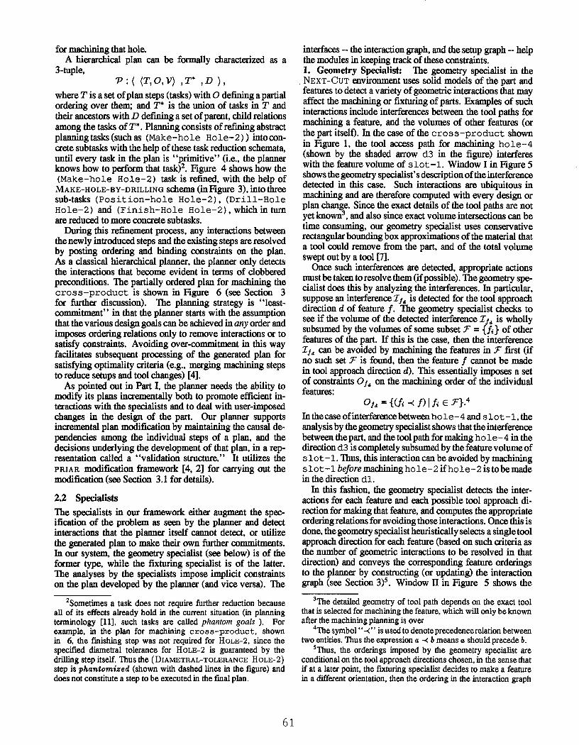
for msc.hinlng that hole.A hierarchical plan can be formally characterized as a
3-tuple,P:(<T,O,];) ,T* ,D ),
where T is a set of plan steps (tasks) with O defining a partialordering over them; and T* is the union of tasks in T andtheir ancestors with D defining a set of parent, child relationsamong the tasks of T*. Planning consists of refining abstractplanning tasks (such as (Make-hole Hole-2) ) intocon-crete subtasks with the help of these task reduction schemata,until every task in the plan is "primitive" (i.e., the plannerknows how to perform that task)2. Figure 4 shows how the(Make-hole Hole-2) task is refined, with the help ofMAKE-HOLE-BY-DRILLING schema (inFignre 3), into threesub-tasks (Position-hole Hole-2), (Drill-HoleHole-2) and (Finish-Hole Hole-2), which in tunlare reduced to more concrete subtasks.
During this refinement process, any interactions betweenthe newly introduced steps and the existing steps are resolvedby posting ordering and binding constraints on the plan.As a classical hierarchical planner, the planner only detectsthe interactions that become evident in terms of clobberedpreconditions. The partially ordered plan for machining thecross-product is shown in Figure 6 (see Section for further discussion). The planning strategy is "least-commitment" in that the planner starts with the assumptionthat the various design goals can be achieved in any order andimposes ordering relations only to remove interactions or tosatisfy constraints. Avoiding over-commitment in this wayfacilitates subsequent processing of the generated plan forsatisfying optimality criteria (e.g., merging machining stepsto reduce setups and tool changes) [4].
As pointed out in Part I. the planner needs the ability tomodify its plans incrementally both to promote efficient in-teractions with the specialists and to deal with user-imposedchanges in the design of the part. Our planner supportsincremental plan modification by maintaining the causal de-pendencies among the individual steps of a plan, and thedecisions underlying the development of that plan, in a rep-resentation called a "validation structure." It utilizes thePRIAR modification framework [4, 2] for carrying out themodification (see Section 3.1 for details).
2.2 Specialists
The specialists in our framework either augment the spec-ification of the problem as seen by the planner and detectinteractions that the planner itself cannot detect, or utilizethe generated plan to make their own further commitments.In our system, the geometry specialist (see below) is of theformer type. while the fixturing specialist is of the latter.The analyses by the specialists impose implicit constraintson the plan developed by the planner (and vice versa). The
ZSometimes a task does not require further reduction becauseall of its effects already hold in the current situation (in planningterminology [11], such tasks are called phantom goals ). Forexample, in the plan for machining croaa-product, shownin 6, the finishing step was not required for HOLE-2, since thespecified diametral tolerance for HOLE-2 i$ guaranteed by thedrilling step itself. Thus the (DIArVmTRAL-TOLERANCP. HOLE-2)step is phantomized (shown with dashed lines in the figure) anddoes not constitute a step to be executed in the final plan.
interfaces -- the interaction graph, and the setup graph -- helpthe modules in keeping track of these constraints.1. Geometry Specialist: The geometry specialist in theNEXT-CUT environment USes solid models of the part andfeatures to detect a variety of geometric interactions that mayaffect the machining or fixturing of parts. Examples of suchinteractions include interferences between the tool paths formachining a feature, and the volumes of other features (orthe part itself). In the case of the cross-product shownin Figure 1, the tool access path for machining hole-4(shown by the shaded arrow 63 in the figure) interfereswith the feature volume of slot-1. Window I in Figure 5shows the geometry specialist’s description of the interferencedetected in this case. Such interactions are ubiquitous inmachining and are therefore computed with every design orplan change. Since the exact details of the tool paths are notyet knowna, and also since exact volume intersections can betime cons, ming, our geometry specialist uses conservativerectangular bounding box approximations of the material thata tool could remove from the part, and of the total volumeswept out by a tool [7].
Once such interferences are detected, appropriate actionsmust be taken to resolve them (if possible). The geometry spe-cialist does this by analyzing the interferences. In particular,suppose an interference z r, is detected for the tool approachdirection d of feature f. The geometry specialist checks tosee if the volume of the detected interference 7712 is whollysubsumed by the volumes of some subset ~r = {f~ } of otherfeatures of the part. If this is the case, then the interference2-f, can be avoided by machining the features in ~" first (ifno such set 5r is found, then the feature f cannot be madein tool approach direction d). This essentially imposes a setof constraints Of~ on the machining order of the individualfeatures:
0:, = {(fi -~ f) lfi 6 ~r}.4In the case of interference between ho 1 e- 4 and s i o g- 1, theanalysis by the geometry specialist shows that the interferencebetween the part, and the tool path for making ho i e- 4 in thedirection d3 is completely subsumed by the feature volume ofs lot- 1, Thus, this interaction can be avoided by machiningslot-1 beforemac.hininghole-2 if hole-2 is tobe madein the direction dl.
In this fashion, the geometry specialist detects the inter-actions for each feature and each possible tool approach di-rection for making that feature, and computes the appropriateordering relations for avoiding those interactions. Once this isdone, the geometry specialist heuristically selects a single toolapproach direction for each feature (based on such criteria asthe number of geometric interactions to be resolved in thatdirection) and conveys the corresponding feature orderingsto the planner by constructing (or updating) the interactiongraph (see Section 3)s. Window II in Figure 5 shows the
3The detailed geometry of tool path depends on the exact toolthat is selected for machining the feature, which will only be knownafter the machining planning is over
4The symbol"-~" is used to denote precedence relation betweentwo entities. Thus the expression a -~ b means a should precede b.
SThus, the orderings imposed by the geometry specialist areconditional on the tool approach directions chosen, in the sense thatif at a later point, the fixturing specialist decides to make a featurein a different orientation, then the ordering in the interaction graph
61

interaction graph corresponding to the cross-product(note the ordering relation between s 1 o t- 1 and ho i e- 2 ).2. Pixturing Specialist: The objective of the fixturingspecialist is to decide which operations of the plan will bedone in which setup, and to arrive at fixture arrangementsfor locating and restraining the part as it is machined. Thewindows F1-F4 in Figure 7 show a fixturing plan for man-ufacturing cross-product. An important considerationhere is to reduce the number of setups. The operation of thefixturing specialist can be seen as having two phases; withthe first phase consisting of proposing setups and the secondphase consisting of testing them, employing geometric, kine-matic and force calculations. To reduce the number of setups,the fixturing specialist merges the steps of the machiningplan based on the expected orientation of the part (given bythe tool approach direction selected for that feature by thegeometry specialist; see above) during those steps. In thesecond phase, it checks if the part can actually be fixturedin the proposed setups, and selects fixture elements for re-straining the part during maehinlng. This involves selectinga particular sequence (total ordering6) of the proposed setups(consistent with the ordering constraints among plan stepsthat comprise the setup groups), and ensuring that the geom-etry of the work-piece at the start of each setup allows it tobe fixtured satisfactorily. The specific sequence of fixturinggroups that are tested by the fixturing specialist then consti-tutes the fixturing plan. A constraint graph called the "setupgraph," which contains information about the chosen setupgroupings, and the ordering relations among them, acts as theinterface between the fixturing specialist and the planner (seeSection 3).
3 The Planning Cycle
When the specification of a part, such as that ofcross-product as shown in Figure 1, is entered forthe first time, the geometry specialist computes the possiblegeometric interactions between its features (as shown by theexample in Window I of Figure 5). Specific ordering con-straints to avoid these interactions are then conveyed to theplanner via the interaction graph (Window ID.
Given the plan representation discussed in Section 2.1,the interaction graph can be seen as an augmentation tothe top-level specification of the problem. In particular, theinteraction graph can be represented by a directed acyclicgraph (DAG) ~ (F, 09 ) whose nodes are the in dividualfeatures of the part, whose edges define a partial orderingon the machining of different features. From the discussionin Section 2.2, we can see that O9 = U/O1,, where d is
the chosen tool approach direction for feature f, and 01~ isthe set of precedence constraints imposed by the geometryspecialist to resolve any tool path interferences in machiningf in direction d.
The effect of the analysis by the geometry specialist is thatinstead of starting with unordered goals, the planner ordersthem according to the vrestrictions imposed by the interaction
would change. For a more detailed description, see [7].6The need to ground the fixturing cheeks relative to the particular
(intermediate) geometry of the part, and the difficulty of generatingand maintaining partial geometries, are the main reasons why thefLxmring specialist is forced to select a specific total ordering.
Given a new or changed specification:
1. Geometry Speciafist: (Input: The solid model of the part andthe features)Compute geometric interferences and update interaction graph
2. Planner: (Input: Feature specification, interaction graph, setupgraph)
(a) If no machining plan exists, generate one using thefeature specification and the interaction graph. If thereare any tool-holder collisions, backtrack to the geometryspecialist (see Section 3.1).
(b) If a machining plan exists, modify it to accommodatethe new specifications (changes in feature attributes,interaction graph or setup graph), while respecting anyimplicit constraints imposed by the setup graph and theinteraction graph (see Section 3.1)
3. Fixturing Specialist: (Input: Machining plan, feature geome-try, setup graph)
(a) If a fixturing plan does not exist, construct the setupgraph by merging steps of the machining plan. Select asetup sequenceand compute the flxturing details for it. Ifno such total ordering is found, backtrack to the planner(see Section 3.1).
(b) If a fLxturing plan does exist, update the setup graph toreflect changes (if any) in the machining plan. Use it incrementally revise the existing fixturing plan. Updatethe setup graph.
Listing 1. High level description of the planning cycle inNEXT-CUT
graph. In particular, the planner starts with an initial tasknetwork (T’, O’), with T’ containing the set of tasks of theform tl : Achieve(features), and orderings of type
[ ti : Aehieveffeaturei)] "<o, [tj : Achieve(featurej)]
if and only if featurei -~o, feature~. The final plan thusincorporates the orderings imposed by the planner, as well asthose inherited from the interaction graph.
The machining plan for cross-product is shown inFigure 6. (The diamond shaped steps are dommy steps,and steps with dotted boundaries correspond to "phantom"steps, i.e., steps whose intended effects are made true byother steps). Notice in particular that the machining steps forslot-1 and hole-4 (in the lowest branch of the plan inFigure 6) are ordered according to the constraints specifiedby the interaction graph (Window 11 in Figure 5).
Next, based on this plan, the fixturing specialist choosessetups for fixturing. From the planner’s view point, thefixturing specialist is partitioning the plan steps into groups,based on a set of equivalence classes defined in terms ofthe expected orientations of the part during plan execution.Such a partitioninginduces an implicit partial ordering amongthe setups. As discussed in Section 2.2, this partitioning isfollowed by checks to ensure that some total order of setupsconsistent with these this partial ordering can actually befixtured.
The setup graph can thus be seen as a DAG S : 04), O,)where each member w 6 }N is a set of plan steps that can bemachined in a partictdar setup, and O, is a partial orderingon the setups, induced by the corresponding partial ordering
62

Figure 4: Reducing an abstract task into concrete sub-tasks
.... .f ~- -
)l)eralions of )la. PL/~II-9~ g.~ t, ~ c t ~, J :~ ,0x.,l i[;i am i|1 alhere is an Interlerence betweenSLOI SLOT-I and TOOL-PATH TOOL-PATII-31.Its volume Is 1.92% of the volume of SLOT-1and 16.39% of the volume of TOObPATH-31.
Its volume characteristic Is PERPENDICULAR OVERLAPIts intersection In the X direction Is ENCLOSE[}.In the Y direction Is ENCLOSING.and In the Z direction Is ENCLOSING.
$
Figure 5: Detecting and Resolving geometric interactions for the cross-product
Figure 6: Msehini.g plan for the cro s s-pro duct
63

YPEOUT WINDOW 4
VPEOUT WINDOW 7F’-£
VPEOUT WINDOW 1
||L|¢T.FIXTUIt li-| ||L|CT-FIXlUI~|-$ IIHO-I
I
, SELECT-FDgIURE-1A. Operation (MILL SLOT,4)B, Operation (MILL SLOT-~)
SELECT-FIgURE-3A, Oper~ion (MILL SLOT-a)B, OptrzUon (MILL SLOT-l)C, Operation (CENTER-ORILL HOLE-4)D. Operation (DRILL HOLE-4)
SELECT-FIXI1JRE-5A. Operation (CENTER-DRILL HOLE-8)B. OperaUon (DRILL HOLE~)
SELE CT-FD(11JR £-~A. OperzUon (CEh,q’ER-DR|LL ROLE-?.B. Operation (DRILL HOLE-g)C. Operation (DRILLHOLE--1) .[[’-B
Figure 7: FixmringPlan for the cross-product
on the plan steps.The ¢onstrnints on the setup-graph from the planner’s
viewpoint are that 142 be a set of mutually exclusive andexhaustive subsets of tasks in T, such that the partitioning isconsistent with the partial ordering among the tasks. To ensurethe latter, the following two constraints must be satisfied:
I. VoJ EW, Vtz,t2Ew ~tETs.t.t~w A(t] ~t-~ t~)2. Vwz, w2 E W if there exists a task t]E wz and t2 6 w2
such that tl -~ t2 in the plan, then it should necessarilybe the case that wl -~o. ¢o2
O, thus defines the partial ordering induced among the setupsas a result of merging the steps of the plan.
For the cross-product example, Window II-A in Fig-ure 7 shows the setup group mergings computed, and Win-dow II-B shows the description of the individual plan stepsmerged under each setup group. Notice that the graph ispartially ordered at this point.
From thepoint of view offixturing spedalist, each w E Wis a fixturing group. In general, once the fixturing specialistmakes a merging of the plan steps according to the aboveconstraints, there is an implicit partial ordering among thefixturing groups (as stated in the condition ii above). Fromthe standpoint of fixturing, this merging is consistent as longas the fixturing specialist can find a sequence of the setupgroups consistent with this partial ordering, which satisfiesthe fixturing constraints (see Section 2.2). To this end. thefixturing specialist first selects a total order on S basedon some heuristic considerations [7], and then carries out
fixturing analysis in accordance with that sequence7. Oncea totally ordered sequence of setups is selected, that furtherconstrains the orderings among the steps of the machiningplan implicitly. In particular, selecting a total order on asetup graph ,S : {W, O,) is equivalent to adding a set ofadditional ordering relations OF among the setups in W suchthat O, u Or, induces a total order on S. Every new orderingwi -~o~, wj among setups translates to additional orderingsamong plan steps such that Vii E wi and Vtj E w j, ti -~ tj(even if ti and tj do not have any ordering relations imposedamong them by the geometry specialist or the planner).Such implicit constraints have to be respected to ensureconservatism of any future plan revision (see Section 3.1).
For the cros s-product example, the fixturing special-ist selects one total ordering (shown in Window 11/in Figure7) consistent with this graph that is satisfactory from thefixturing viewpoint, and computes a fixturing plan (in eachfixture setup, the features to be mam.tfactured in that setupare shown highlighted). It then updates the setup graph withadditional orderings corresponding to the selected sequence.The windows F- 1 to F-4 in Figure 7 show the details of thefixturing plan. At this point, we have a complete process planfor machining cross-product (See Section ID.
7Notice that different setup sequences have differing fixturingproperties as they correspond to different intermediate geometriesof the part during machining
6~

3.1 Backtracking and Incremental Plan Revision
When inconsistencies arise between the commitments madeby the planner and the specialists, the linear control flowdiscussed in Section 3 disrupted, and backtracking is neces-sitated. When this happens, there are in general a varietyof backtracking alternatives, some intra-module, and someinter-module, each presenting a different set of tradeoffs. Theinter-module backtracking is guided by the interfaces betweenthe planner and the specialists. Such inter-module backtrack-ing is often costly. To contain this, and to improve efficiencyof the overall planning, it is important for individual modulesto have the ability to accommodate changes in their spec-ifications by incrementally modifying their plans. Similarrevision is also necessitated in response to designer initiatedspecification changes. In both cases, the revision needs to beconservative both to ensure internal efficiency of planning,as well as to contain the ripple effects of changes in the planon the analyses of other modules. Furthermore, to improvethe overall efficiency, the planner’s ability to reuse its planswill have to be supplemented by the specialists’ ability toreuse their previous analyses. In our implementation, both theplanner and the fixturing specialist have the ability to reuseprevious results. While each module maintains the internaldependencies on its plans, the external (inter-module) depen-dencies are maintained through the interfaces. The planneruses the PRIAR modification framework, developed in ourearlier work [2, 3] to carry out plan revision. See [8] forfurther discussion.
4 Results
The planning architecture described in the previous sectionshas been implemented as a prototype on top of the NEXT-CUT planning framework. Several empirical studies havebeen conducted on this architecture [8]. We found that thearchitecture avoids duplicating capabilities of the specialistsin the planner, thereby eliminating redundancy, and improv-ing efficiency and modularity. Our implementation wasable to automatically generate process plans that satisfy theconstraints of geometry, machining, and fixturillg specialistscooperating in an integrated framework. The architectureprovides a first account of how a general purpose planner canbe integrated with a set of specialists. We developed inter-faces between the planner and the specialists that allow bothto explicitly keep track of externally imposed constraints.In the case of the planner, all the external constraints havebeen modeled as additional orderings and mergings amongmachining steps. We found that these interfaces allow theplanner to function with a minimal understanding of the in-ternal operations of the specialists, or the domain specificknowledge they employ. We also found that the ability toincrementally modify existing plans to accommodate externalconstraints effectively controls the proliferation of secondaryinteractions, in the event inconsistent commitments betweenthe planner and the specialists are detected.
Part IIIRetropsective Analysis
In the following, I attempt to address some of the questionsraised by the symposium CFP in the context of the NEXT-CUT process planning system.
What was the most difficult aspect of this problem?
The difficult aspects of this problem include the necessityof deep geometric and force based analyses, the requirementof optimal partially ordered plans (which can give rise to leastnumber of setups), the requirement for adequate communi-cation between the planner and the specialized reasoners andthe h~lmans that it interacts with.
What did you think would be difficult that was surprisinglyeasy?
At the outset, I thought that the most difficult thing wouldbe the combinatorics of action-interactions (as is the case indomains like blocks world). In the end, I found that thenormal interaction detection and resolution phase takes uprelatively small amount of time in process planing domain.
Although there are some interactions between machiningoperations (e.g., center drilling should come before the corre-sponding driUing operation), these inteactions can be avoidedby packaging primitive machining operations into plan frag-ments. The task reduction planning framework, used in thenextcut process planning domain, provides good support forthis. The real cost is in detecting the geometric interactions,and optimzing the partial plan to get least number of set upsin fixture planing.
If you used a hybrid solution, why?
As mentioned earlier, we did use a hybrid solution, wherean AI planner was used to do the machining planning, whilea solid modeler and a fixture planner were used to do thegeometric reasoning and fixture planning respectively. Thereasons for going for hybrid solution are: (i) to avoid rein-venting geometry and force-based reasoning within a STRIPSaction representation (apart from the obvious inefficienciesof such a reinvention, it would also have the drawback ofalmost surely alienating the user group!) (ii) to exploit the al-ready existing methods for dealing with geometric and fixtureplanning.
Lessons learned from the implementation
The implementation has also taught us several general prin-ciples on desi£nlng hybrid planning systems; we snmmarizethem briefly below:
¯ Communication between the planner and the specialiststakes several forms, including the shared representationof the design and process plan, specialized representa-tions of mutual constraints (e.g, the setup graph) andstandardized messages (e.g., the results of intersectiontests from the geometry specialis0. In all cases, thereis a tradeoff between expressiveness and abstraction.For example, the geometric intersection results, as inWindow I of Figure 5, were found after some experi-mentation to be at the right level of detail for making
65

ordering decisions in process planning. More generally,it will be impossible to satisfy a variety of modules withmessages and representations at a single level of detail.A solution to this problem may be to exploit hierarchicalrepresentations.
¯ Modules in a hybrid planning environment benefit fromhierarchical representations and least commitment ap-proach in problem solving which keeps options openand reduces the need for backtracking in the face ofspecification changes and planning conflicts (by allow-ing maximum latitude to the specialists in generalizingrefining the plan according to their constraints). Inour implementation, for example, we maintain partiallyordered machining plans, and setup graphs,s
¯ Each module should reuse previous results wheneverpractical, both for speed and to make the effects ofdesign changes manifest. Reuse of previous results isparticularly useful in managing the interactions betweenthe planners and the specialists. Every time a modulecomputes a new result, it is possible that it may invalidateresults previously computed by other modules. However,to the extent that each module reuses previous results,the incidence of new side-effects and interactions withother modules is reduced. Thus, if the process plannermakes only minor changes to a previous process plan,it is unlikely that major changes will be needed in thecorresponding fixture plan.
¯ The ability to reuse previous plans (and analysis results),as well as to control inter-module backtracking hingesprimarily on keeping track of dependencies within theplans and between the plans, the specifications and theexternal constraints imposed by other modules. Inter-faces which keep track of externally imposed constraintscan thus play an important role in facilitating reuse.More generally, we found that it is important to keepissues of feasibility (constraints) separate from issues optimality (costs) since the former are far more likely remain valid from one plan iteration to the next.
Experience with our implementation makes us believe thathybrid architectures such as the one explored here offera promising avenue of research for dealing with realisticplanning domains.
References[1] T.-C. Chang and R.A. Wysk. An Introduction to Automated
Process Planning Systems. International Series in Industrialand Systems Engineering. Prentiee-HaU, 1985.
[2] S. Kambhampatiand J. Hendler, "A validation structure basedtheory of plan modification and reuse," Artificial Intelligence,Vol. 55, 1992.
[3] S. Kambhampati. Exploiting Causal Structure to ControlRetrieval and Refitting during Plan Reuse ComputationalIntelligence, Vol. 10, No. 2, May 1994, pp 213-245.
80f course, the usualtradeoffholds between the delay of commit-ment and the amount of computation needed to check the consistencyof the plan. Thus, in the example of the fixturing specialist, to avoidextensive geometric simulation, a single total-ordering of the setupsis ultimately chosen for detailed fLxture planning.
[4] S. Kambhampati and M. R. Cutkosky, "An approach towardincremental and interactive planning for concurrent productand process design," in Proceedings of ASME Winter An-nual Meeting on Computer Based Approaches to ConcurrentEngineering, November 1990.
[5] S. Kambhampati and J. Tenenbaum, "Planning in concur-rent domains," in DARPA 1990 Workshop on Innovative Ap-proaches to Planning, Scheduling and Control, 1990.
[6] S. Kambhampati, M. Cutkosky, J. M. Tenenbanm, and S. LeeCombining specialized reasoners and general purpose planners:A case study. In Prec. of9th AAAI, 1991.
[7] S.H. Lee, M. R. Cutkosky, and S. Kambhampati, "Incrementaland interactive geometric reasoning for fLxture and processplanning," in Issues in Design~Manufacture Integration 1991(A. Sharon, ed.), pages 7--13, ASME Winter Annual Meeting,ASME, December 1991.
[8] S. Kambhampati, M. Cutkosky, J. M. Tenenbaum, and S. Lee.Integrating general purpose planners and specialized reasoners:case study of a hybrid planning architecture. IEEE Trans. onSystems, Man and Cybernetics (Special section on planning,scheduling and control). Vol. 23, No. 6, November 1993.
[9] S. Kambhampati, C. Knoblock and Q. Yang. Planning asRefinement Search: A Unified framework for evaluating designtradeoffs in partial order planning. ASU-CSE-TR 94-002. Toappear in Artificial Intelligence special issue on Planning andScheduling. 1995.
[10] S. Kambhampati. A comparative analysis of partial order plan-ning and task reduction planning SIGART Bulletin, SpecialSection on evaluating plans, planners and planning agents.Vol. 6, No. 1, January 1995.
[11] E. Sacerdoti, A Structure for Plans and Behavior. New York:Elsevier North-Holland, 1977.
[12] A. Tate, "Generating project networks," in Proceedings of5th International Joint Conference on Artificial Intelligence,pages 888--893, 1977.
[13] D. Wilkins, "Domain independent planning: Representationand plan generation," Artificial Intelligence, vol. 22, pages269--301, 1984.
66