nx topology optimization for designers · • works in the nx cad work part in the context of an...
TRANSCRIPT

NX Topology Optimization for
DesignersGuy Wills – Topology Optimization Product Manager
Unrestricted ©Siemens AG 2017

Unrestricted © Siemens AG 20182017.MM.DDPage 2 Siemens PLM Software
Agenda
• Product Highlights
• Uses for Topology Optimization results
• Model Construction Opportunities
• Optimization Features
• Design Constraints
• FE Loads & Constraints
• Materials
• Optimization
• Results
• Summary
Unrestricted © Siemens AG 20182017.MM.DDPage 3 Siemens PLM Software
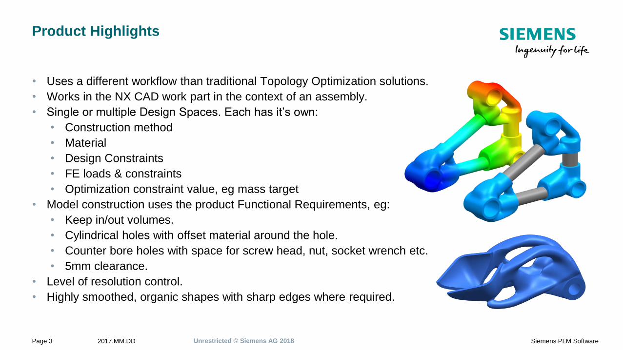
Product Highlights
• Uses a different workflow than traditional Topology Optimization solutions.
• Works in the NX CAD work part in the context of an assembly.
• Single or multiple Design Spaces. Each has it’s own:
• Construction method
• Material
• Design Constraints
• FE loads & constraints
• Optimization constraint value, eg mass target
• Model construction uses the product Functional Requirements, eg:
• Keep in/out volumes.
• Cylindrical holes with offset material around the hole.
• Counter bore holes with space for screw head, nut, socket wrench etc.
• 5mm clearance.
• Level of resolution control.
• Highly smoothed, organic shapes with sharp edges where required.

Unrestricted © Siemens AG 20182017.MM.DDPage 4 Siemens PLM Software
Uses for Topology Optimization Results
Topology Optimization is not the finish, for many parts
it’s just the start. Many opportunities exist to use the
Topology Optimization results.
1. Direct to AM machine for printing.
2. Direct to cast, mold or multi-axis machining.
3. Use for further Design or Simulation using
Convergent models.
4. Further Optimization work.
4. Guidance for re-modelling using traditional CAD
tools.
Holes cut into Convergent Facet model

Unrestricted © Siemens AG 20182017.MM.DDPage 5 Siemens PLM Software
Why Topology Optimization ?
Wikipedia… Topology Optimization is a mathematical
method that optimizes material layout within a given
design space, for a given set of loads, boundary
conditions and constraints with the goal of maximizing
the performance of the system.
Original Design
Functional Requirements
Technology that is best applied when searching for new
or improved designs based on the functional
requirements. Starting from a pre-designed model to trim
off 10% of the weight is difficult as the design is already
“optimized”, probably by hand.
Topology Optimization traces out the “load paths” that
connect between where the loads are applied and the
constraints. Keep In areas that have no loads might not
be connected by the optimizer.

Demo & Hands On Exercise
Unrestricted © Siemens AG 20182017.MM.DDPage 8 Siemens PLM Software
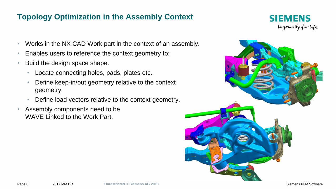
Topology Optimization in the Assembly Context
• Works in the NX CAD Work part in the context of an assembly.
• Enables users to reference the context geometry to:
• Build the design space shape.
• Locate connecting holes, pads, plates etc.
• Define keep-in/out geometry relative to the context
geometry.
• Define load vectors relative to the context geometry.
• Assembly components need to be
WAVE Linked to the Work Part.
Unrestricted © Siemens AG 20182017.MM.DDPage 9 Siemens PLM Software
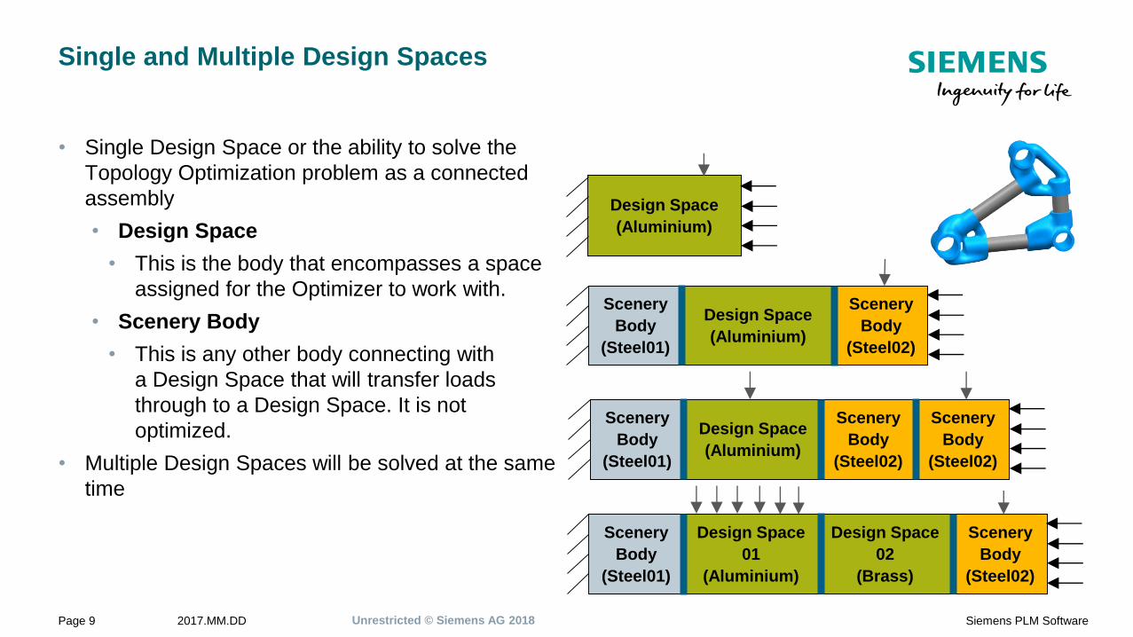
Single and Multiple Design Spaces
• Single Design Space or the ability to solve the
Topology Optimization problem as a connected
assembly
• Design Space
• This is the body that encompasses a space
assigned for the Optimizer to work with.
• Scenery Body
• This is any other body connecting with
a Design Space that will transfer loads
through to a Design Space. It is not
optimized.
• Multiple Design Spaces will be solved at the same
time
Design Space
(Aluminium)
Scenery
Body
(Steel01)
Design Space
(Aluminium)
Scenery
Body
(Steel02)
Scenery
Body
(Steel01)
Design Space
(Aluminium)
Scenery
Body
(Steel02)
Scenery
Body
(Steel02)
Scenery
Body
(Steel01)
Design Space
02
(Brass)
Scenery
Body
(Steel02)
Design Space
01
(Aluminium)
Unrestricted © Siemens AG 20182017.MM.DDPage 10 Siemens PLM Software
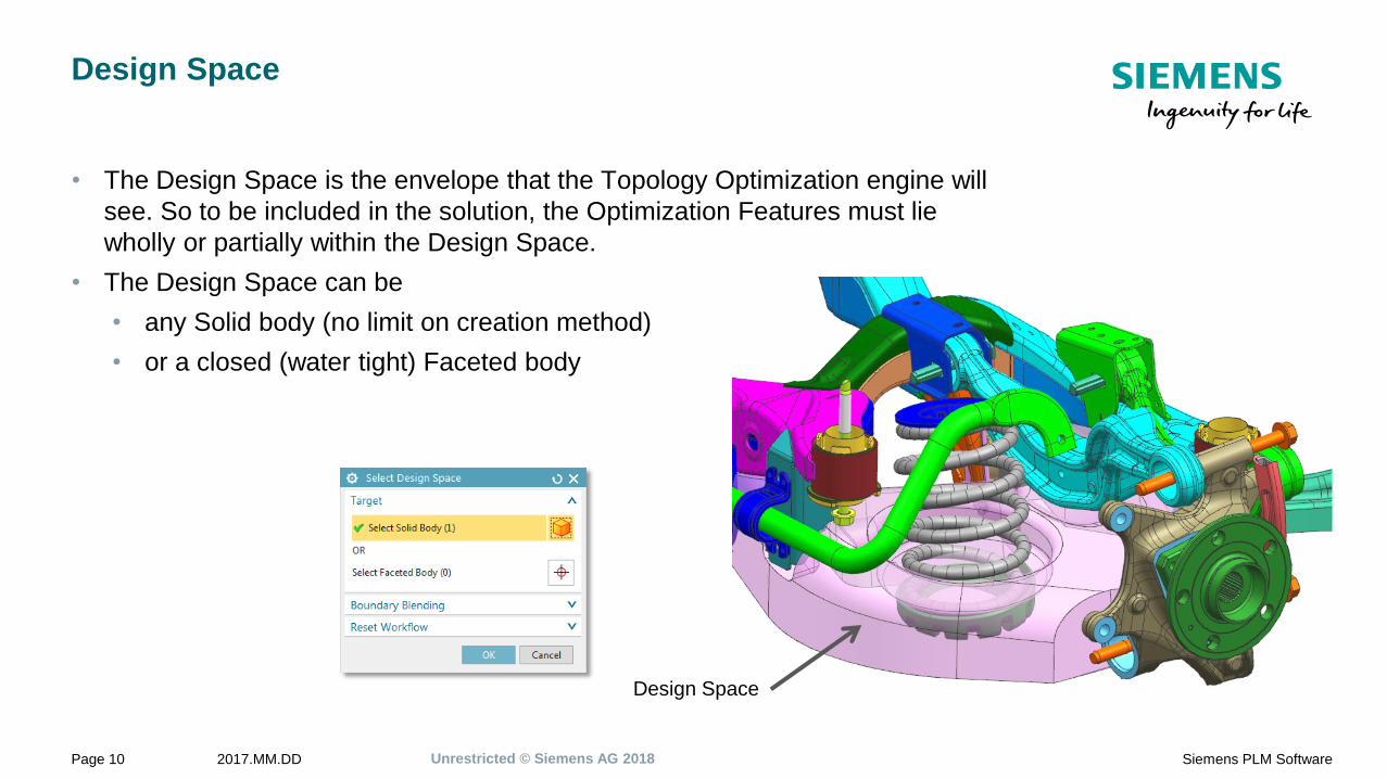
Design Space
• The Design Space is the envelope that the Topology Optimization engine will
see. So to be included in the solution, the Optimization Features must lie
wholly or partially within the Design Space.
• The Design Space can be
• any Solid body (no limit on creation method)
• or a closed (water tight) Faceted body
Design Space

Unrestricted © Siemens AG 20182017.MM.DDPage 11 Siemens PLM Software
Manage Bodies
Bodies that are to be used as a Design
Space or for Scenery.
Bodies must exist in the Work Part.
Design Spaces
• Design Constraints
• Optimization Features
• Loads
Scenery bodies
• Optimization Features
• Loads
Table Reordering
Unrestricted © Siemens AG 20182017.MM.DDPage 13 Siemens PLM Software
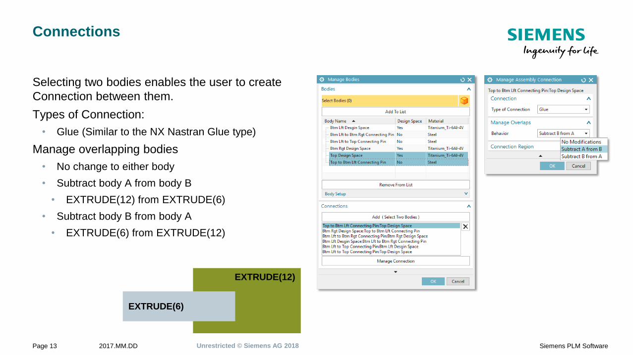
Connections
Selecting two bodies enables the user to create
Connection between them.
Types of Connection:
• Glue (Similar to the NX Nastran Glue type)
Manage overlapping bodies
• No change to either body
• Subtract body A from body B
• EXTRUDE(12) from EXTRUDE(6)
• Subtract body B from body A
• EXTRUDE(6) from EXTRUDE(12)
EXTRUDE(12)
EXTRUDE(6)

Unrestricted © Siemens AG 20182017.MM.DDPage 15 Siemens PLM Software
Optimization Features
• Design Spaces and Scenery Body can have Optimization Features.
• Functional Requirements are described by the use of Optimization Features.
• Some NX modelling features are mapped to the optimization application
features. These include the following types:
• Cylinder, Block and Sphere primitives
• Copy Face
• Simple Hole
• Counter Bored Hole
• Further solid bodies (no limit on creation method) can also be added to the
Optimization Features list.
• The Design Space is the envelope that the Topology Optimization engine will
see. So to be included in the solution, the Optimization Features must lie
wholly or partially within the Design Space.

Unrestricted © Siemens AG 20182017.MM.DDPage 16 Siemens PLM Software
Optimization Features
Optimization Features can describe Functional Requirements. For example:
• M8 Bolt connection that requires a clearance for a socket wrench.
• CounterBored hole feature with a hole diameter of 8mm and 30mm
diameter counter bore diameter. Counter bore length long enough to
allow socket wrench access.
• A cone shaped boss is required.
• Keep-In cylinder with draft, or cone primitive, or extruded circle with
draft, etc.
• Min of 10m clearance to avoid another component in the assembly.
• Wave Linked Body of the component with an 10mm offset for safety.
• A force is only applied to a specific part of a face.
• The face is split to define the limit of the load applied and a Copy Face
feature used to define the optimization feature.
Unrestricted © Siemens AG 20182017.MM.DDPage 17 Siemens PLM Software
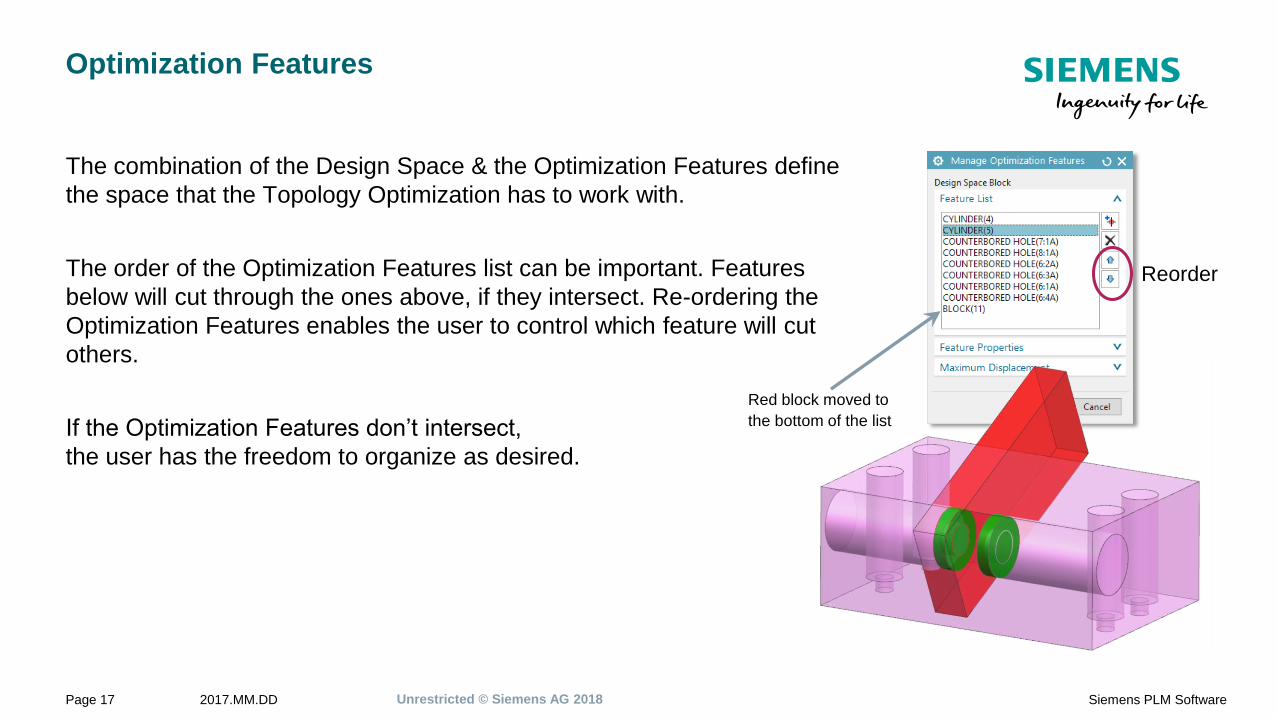
Optimization Features
The combination of the Design Space & the Optimization Features define
the space that the Topology Optimization has to work with.
The order of the Optimization Features list can be important. Features
below will cut through the ones above, if they intersect. Re-ordering the
Optimization Features enables the user to control which feature will cut
others.
If the Optimization Features don’t intersect,
the user has the freedom to organize as desired.
Reorder
Red block moved to
the bottom of the list
Unrestricted © Siemens AG 20182017.MM.DDPage 18 Siemens PLM Software
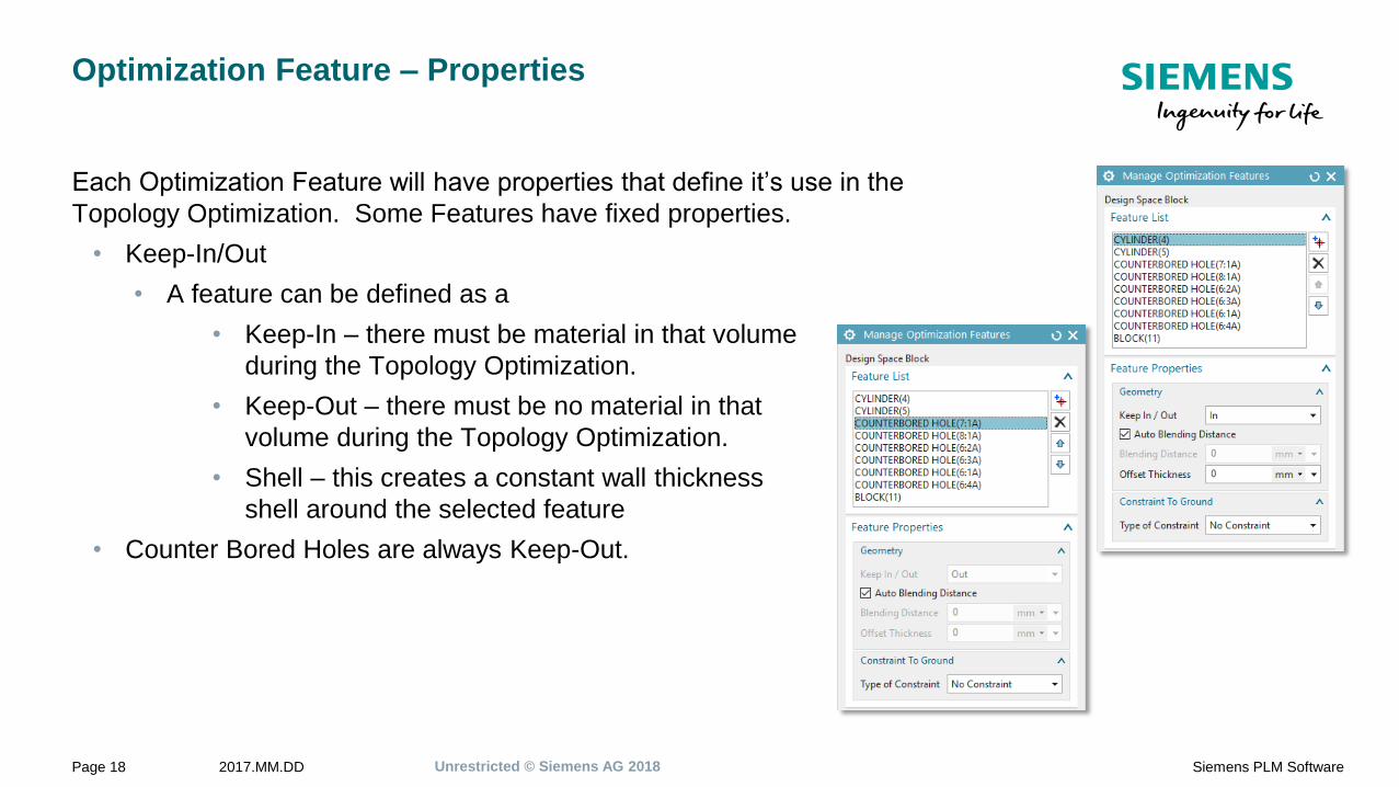
Optimization Feature – Properties
Each Optimization Feature will have properties that define it’s use in the
Topology Optimization. Some Features have fixed properties.
• Keep-In/Out
• A feature can be defined as a
• Keep-In – there must be material in that volume
during the Topology Optimization.
• Keep-Out – there must be no material in that
volume during the Topology Optimization.
• Shell – this creates a constant wall thickness
shell around the selected feature
• Counter Bored Holes are always Keep-Out.
Unrestricted © Siemens AG 20182017.MM.DDPage 19 Siemens PLM Software
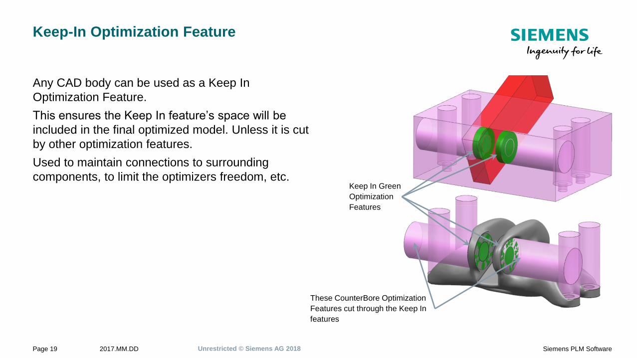
Keep-In Optimization Feature
Any CAD body can be used as a Keep In
Optimization Feature.
This ensures the Keep In feature’s space will be
included in the final optimized model. Unless it is cut
by other optimization features.
Used to maintain connections to surrounding
components, to limit the optimizers freedom, etc.Keep In Green
Optimization
Features
These CounterBore Optimization
Features cut through the Keep In
features

Unrestricted © Siemens AG 20182017.MM.DDPage 20 Siemens PLM Software
Keep-Out Optimization Feature
Any CAD body can be used as a Keep Out
Optimization Feature.
A Keep Out Optimization Feature tells the optimizer
that no material can be placed in this space.
Some Optimization Features are pre-defined as Keep
Out features, these include:
• SimpleHole
• CounterBore Hole
Keep Out
CounterBore
HolesKeep Out
Block

Unrestricted © Siemens AG 20182017.MM.DDPage 21 Siemens PLM Software
Shell Optimization Feature
A Shell Optimization Feature is similar to the NX CAD Shell command creating
a uniformly thick offset of the body.
Offset Thickness value defines the wall thickness of the Shell.

Unrestricted © Siemens AG 20182017.MM.DDPage 22 Siemens PLM Software
Optimization Feature – Properties
• Offset Thickness
• To define a hole it must have material around the
hole. This is the Offset Thickness on a Hole feature.
• Offset of a solid Keep-Out body.
• Offset of Copy Face features (similar to an NX
Thicken feature).
Offset Thickness
around a solid
Keep-Out body
Offset Thickness on a
CopyFace feature
Offset Thickness on
a Hole feature
Unrestricted © Siemens AG 20182017.MM.DDPage 23 Siemens PLM Software
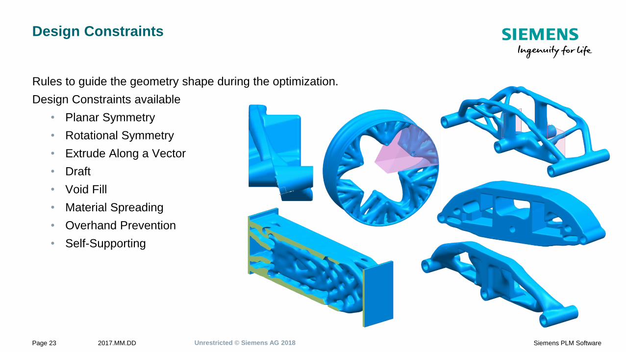
Design Constraints
Rules to guide the geometry shape during the optimization.
Design Constraints available
• Planar Symmetry
• Rotational Symmetry
• Extrude Along a Vector
• Draft
• Void Fill
• Material Spreading
• Overhand Prevention
• Self-Supporting

Unrestricted © Siemens AG 20182017.MM.DDPage 24 Siemens PLM Software
Design Constraints – Planar Symmetry
Planar Symmetry
• Single or dual symmetry planes.
• Only half (or quarter) Design Space required.
• Whole model returned with blending across the symmetry plane(s).
Two Symmetry Planes
Single Symmetry Plane

Unrestricted © Siemens AG 20182017.MM.DDPage 25 Siemens PLM Software
Design Constraints – Planar Symmetry
Global Symmetry option
• With – Model is constructed as a segment and the results are completely symmetric.
• Without – Model is constructed as a whole, and the results are as symmetric as
possible.
With “Needs Global Symmetry”
Without “Needs Global Symmetry”

Unrestricted © Siemens AG 20182017.MM.DDPage 26 Siemens PLM Software
Design Constraints – Rotational Symmetry
Rotational Symmetry
• Only a segment is required for the Design Space.
• Whole model returned with blending between the segments.
Stress Results
Unrestricted © Siemens AG 20182017.MM.DDPage 27 Siemens PLM Software
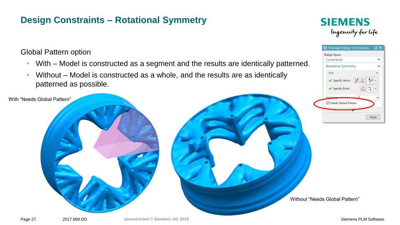
Design Constraints – Rotational Symmetry
Global Pattern option
• With – Model is constructed as a segment and the results are identically patterned.
• Without – Model is constructed as a whole, and the results are as identically
patterned as possible.
With “Needs Global Pattern”
Without “Needs Global Pattern”
Unrestricted © Siemens AG 20182017.MM.DDPage 28 Siemens PLM Software
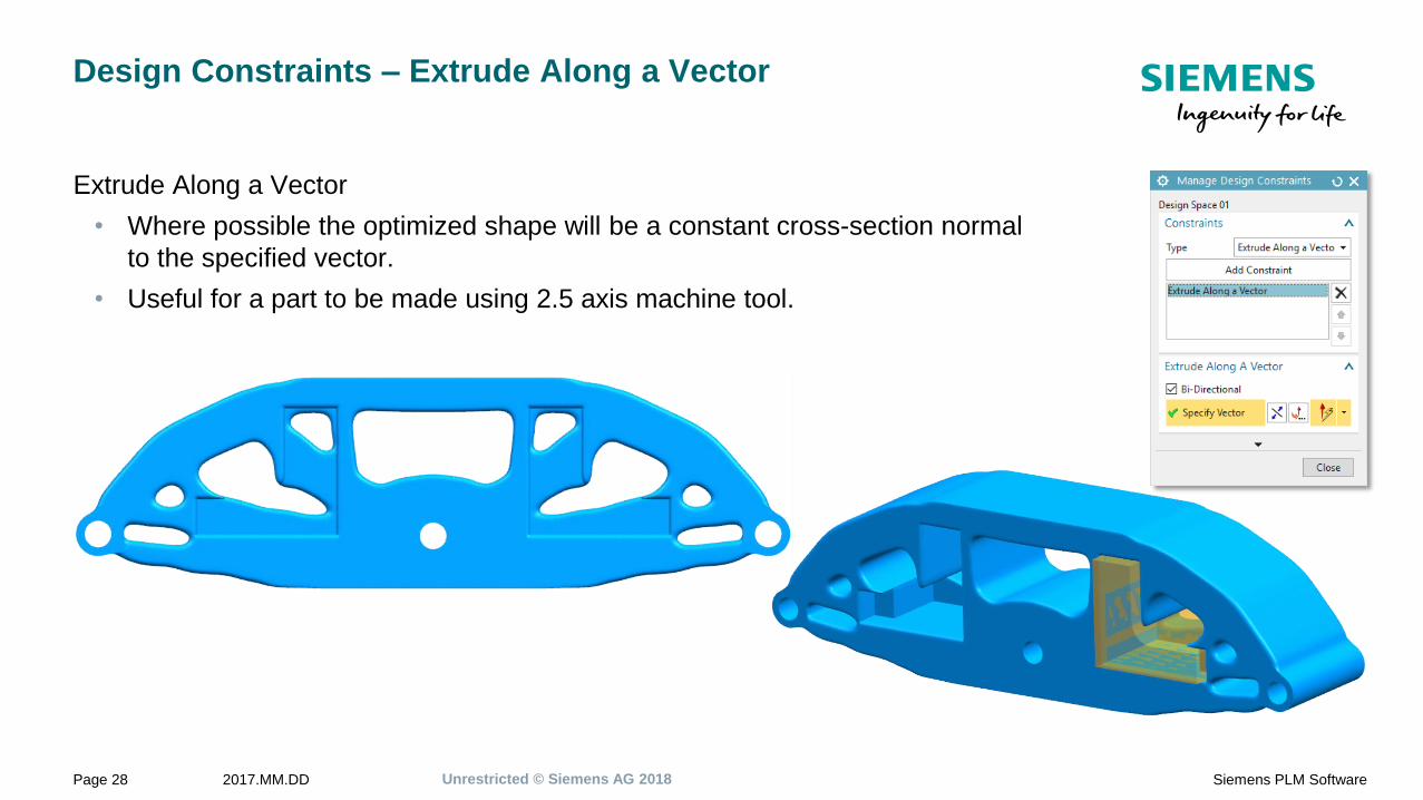
Design Constraints – Extrude Along a Vector
Extrude Along a Vector
• Where possible the optimized shape will be a constant cross-section normal
to the specified vector.
• Useful for a part to be made using 2.5 axis machine tool.
Unrestricted © Siemens AG 20182017.MM.DDPage 29 Siemens PLM Software
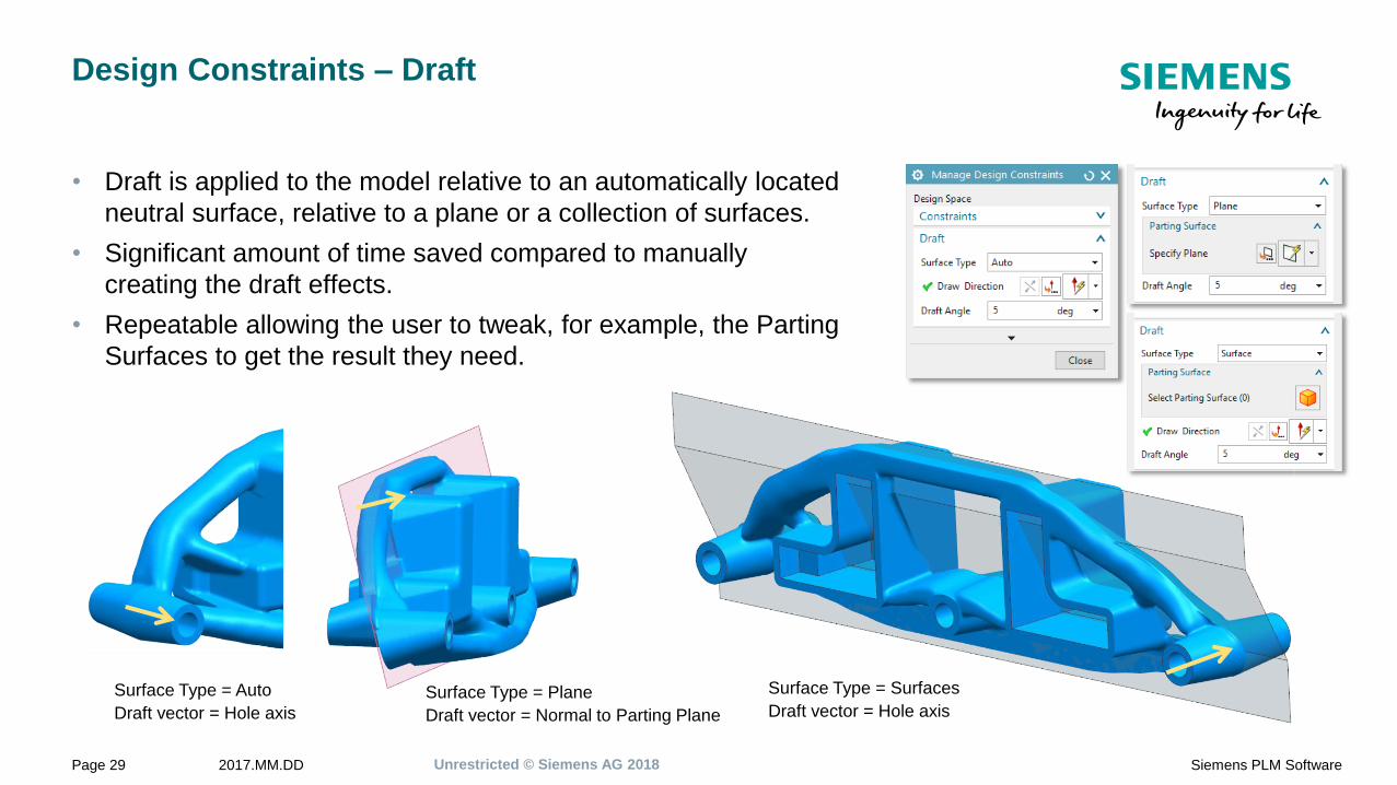
Design Constraints – Draft
• Draft is applied to the model relative to an automatically located
neutral surface, relative to a plane or a collection of surfaces.
• Significant amount of time saved compared to manually
creating the draft effects.
• Repeatable allowing the user to tweak, for example, the Parting
Surfaces to get the result they need.
Surface Type = Auto
Draft vector = Hole axis
Surface Type = Plane
Draft vector = Normal to Parting Plane
Surface Type = Surfaces
Draft vector = Hole axis

Unrestricted © Siemens AG 20182017.MM.DDPage 30 Siemens PLM Software
Design Constraints – Draft example with Mass=35kg
Surface Type = Parting Surfaces
Draft vector = Z
Unrestricted © Siemens AG 20182017.MM.DDPage 31 Siemens PLM Software
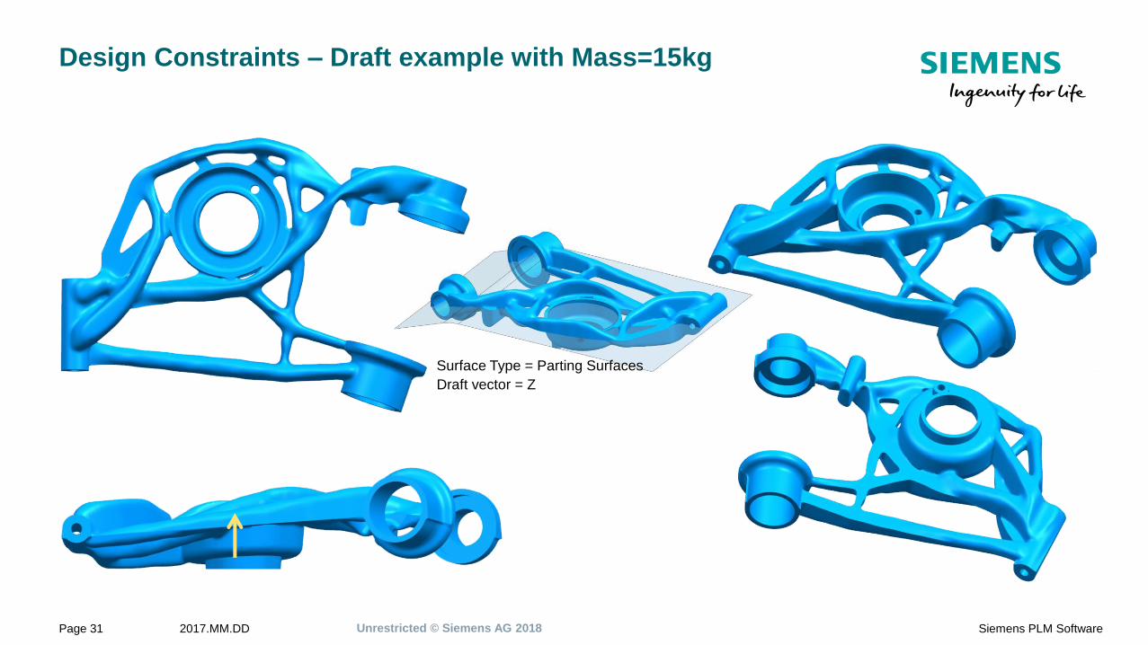
Design Constraints – Draft example with Mass=15kg
Surface Type = Parting Surfaces
Draft vector = Z

Unrestricted © Siemens AG 20182017.MM.DDPage 32 Siemens PLM Software
Design Constraints – Void Fill
Void Fill
• Parts with interior voids will have the voids filled with wasted expensive
metal powder.
• This Design Constraint prevents internal Voids will being created or other
surfaces not directly accessible from outside the part.
Voids

Unrestricted © Siemens AG 20182017.MM.DDPage 33 Siemens PLM Software
Design Constraints – Material Spreading
Material Spreading
• This controls how the material is “pushed apart”.
• Have the model tend towards a hollowed out model, a thing walled model or
a strut like model.
Material
Spreading = 30%
Hollowed out
Material
Spreading = 60%
Thin Walls
Material
Spreading = 100%
Struts

Unrestricted © Siemens AG 20182017.MM.DDPage 34 Siemens PLM Software
Design Constraints – Overhang Prevention
Overhang Prevention
• Prevents geometry overhanging other geometry that would require support
geometry along the specified vector.
• This is important for parts built using a powder bed additive manufacturing
method. Overhanging geometry often requires supports to hold it up during the
manufacturing process. Reducing or removing the need for supports reduces
time and cost to make the part.
No Constraint
Overhang Prevention Constraint

Unrestricted © Siemens AG 20182017.MM.DDPage 35 Siemens PLM Software
Design Constraints – Self-Supporting
Self-Supporting
• The angle to the base plate plane, beyond which that the geometry cannot
support its self as each layer is created during the AM process. This
Constraint ensures the resultant model is not smaller than the angle.
Build
Direction
Part
Base Plate
Self-Supporting
Angle
No Constraint
Self-Supporting &
Overhang Prevention
Constraint
Build
Direction

Unrestricted © Siemens AG 20182017.MM.DDPage 36 Siemens PLM Software
Design Constraints – Multiple Design Constraints
• Applying multiple Design Constraints can produce interesting and
impressive results. And the order they are applied and also change the
result
• In the example shown, the Design Space will have the Planar
Symmetry applied, followed by Extrude Along a Vector. This implies
that Extrude Along a Vector takes precedence over Planar Symmetry
in the case that both cannot be satisfied.
• By selecting a Design Constraint it can be moved Up of Down thus
changing the order the Design Constraints are applied and the
resultant geometry.

Unrestricted © Siemens AG 20182017.MM.DDPage 37 Siemens PLM Software
Design Constraints – Per Design Space
Each Design Space can have
it’s own set of Design Constraints.
Draft
Material Spreading
Fill Void

Unrestricted © Siemens AG 20182017.MM.DDPage 38 Siemens PLM Software
Displacement Constraint
Displacement Constraint can be added to a Optimization
Feature in a Design Space or Scenery Body.
• Magnitude in any direction.
• Magnitude in a specific direction.
Can be used to constrain deformation of the of the model.
Max Displacement in
-Z

Unrestricted © Siemens AG 20182017.MM.DDPage 39 Siemens PLM Software
Load Cases
• Different combination of loads can be applied using Load Cases. For
example, front loads, side loads, top loads, etc. The solution will take all
these different load cases into account.
4x Load case examples
Unrestricted © Siemens AG 20182017.MM.DDPage 40 Siemens PLM Software
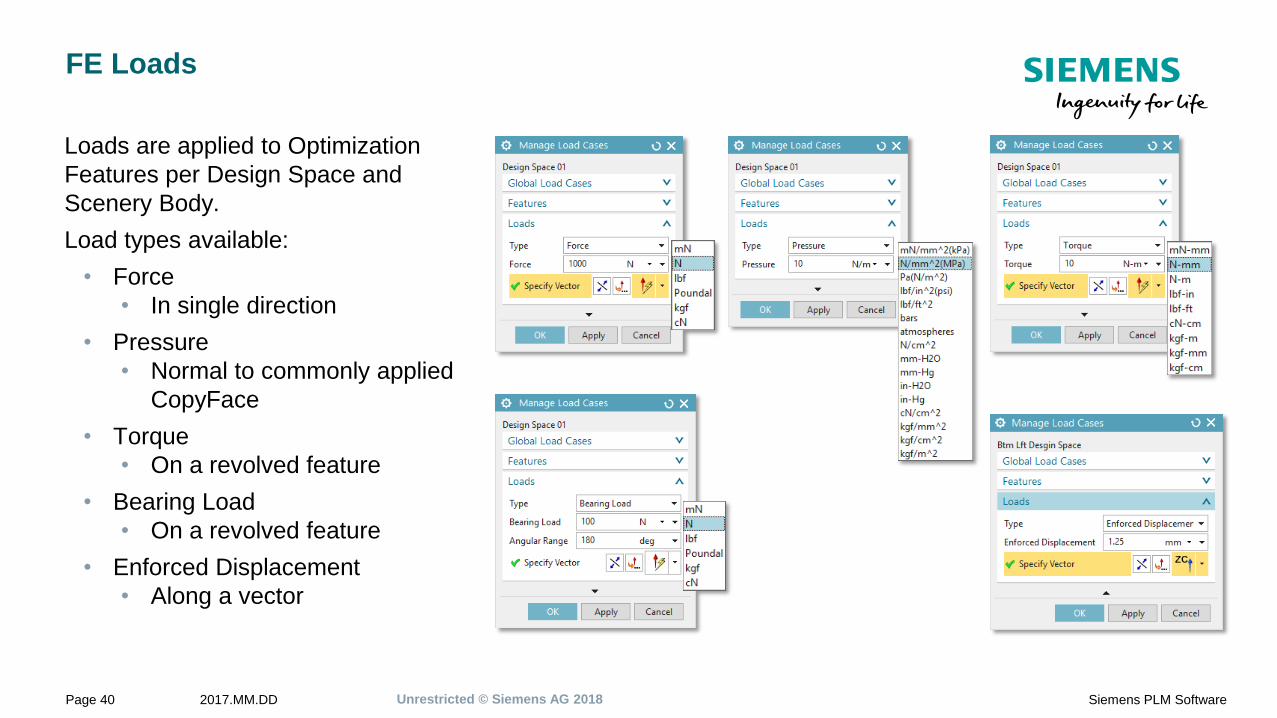
FE Loads
Loads are applied to Optimization
Features per Design Space and
Scenery Body.
Load types available:
• Force
• In single direction
• Pressure
• Normal to commonly applied
CopyFace
• Torque
• On a revolved feature
• Bearing Load
• On a revolved feature
• Enforced Displacement
• Along a vector

Unrestricted © Siemens AG 20182017.MM.DDPage 41 Siemens PLM Software
FE Constraints
Constrain to Ground are applied to
Optimization Features per Design
Space and Design Space.
Constraints available:
• Fixed
• In all directions
• Pinned
• Allowed to rotate about a vector
• Linear Slider
• Allowed to slide in one vector
• Planar Slider
• Allowed to slide in any direction
within a plane

Unrestricted © Siemens AG 20182017.MM.DDPage 42 Siemens PLM Software
Global Loads
Global loads are applied to the whole model.
Global Loads available:
• Acceleration
• Most commonly used to add a Gravity load for geometry that as a
significant mass that can affect the results.
• Temperature
• Used when the part will operate in an area where the temperature is
higher than the normal 20degC
• Note this requires that ALL the materials assigned to the Design
Spaces must have temperature varying properties.

Unrestricted © Siemens AG 20182017.MM.DDPage 43 Siemens PLM Software
Materials
• All Design Space and Scenery bodies must have a Material assigned
before Optimization.
• Any mix of Isotropic & Orthotropic material types are supported.
• Isotropic
• Material properties are the same in all directions. Most commonly
used and properties available.
• Orthotropic
• Material properties vary in X, Y, Z axis.
• Can be used to simulate parts where the properties in the Build
Direction are different to the in-layer plane.
• Orthotropic axis align with the global axis.

Demo & Hands On Exercise

Unrestricted © Siemens AG 20182017.MM.DDPage 45 Siemens PLM Software
Optimizations Types
Combination options of optimization Objective and Constraint:
• Compliance/stiffness based optimization
• Minimize strain energy subject to a mass target
• Stress based optimization
• Minimize mass subject to a safety factor
• Normal modes optimization
• Maximize natural frequency subject to mass target

Unrestricted © Siemens AG 20182017.MM.DDPage 46 Siemens PLM Software
Optimizations Types –
Minimize Strain Energy Subject to a Mass Target
Equivalent to maximize the parts stiffness whilst reducing the
mass to a target value.
• Each Design Space has it’s own Mass Target.
Top Design Space
Mass Target = 0.15kg
Btm Rgt Design Space
Mass Target = 0.12kg
Btm Lft Design Space
Mass Target = 0.10kg

Unrestricted © Siemens AG 20182017.MM.DDPage 47 Siemens PLM Software
Optimizations Types –
Minimize Mass Subject to a Safety Factor
Stress based optimization to minimize the design space
volume subject to Safety Factor applied to the Yield
Stress of the material at 20degC
• Each Design Space has it’s own Safety Factor.
Top Design Space
Safety Factor = 1.1
Btm Rgt Design Space
Safety Factor = 1.0
Btm Lft Design Space
Safety Factor = 1.2
Unrestricted © Siemens AG 20182017.MM.DDPage 48 Siemens PLM Software
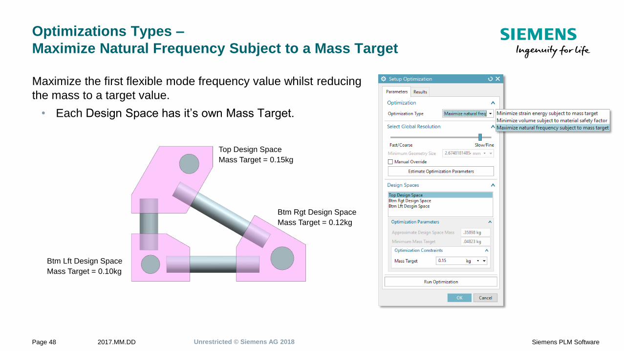
Optimizations Types –
Maximize Natural Frequency Subject to a Mass Target
Maximize the first flexible mode frequency value whilst reducing
the mass to a target value.
• Each Design Space has it’s own Mass Target.
Top Design Space
Mass Target = 0.15kg
Btm Rgt Design Space
Mass Target = 0.12kg
Btm Lft Design Space
Mass Target = 0.10kg
Unrestricted © Siemens AG 20182017.MM.DDPage 49 Siemens PLM Software
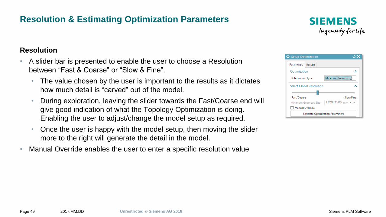
Resolution & Estimating Optimization Parameters
Resolution
• A slider bar is presented to enable the user to choose a Resolution
between “Fast & Coarse” or “Slow & Fine”.
• The value chosen by the user is important to the results as it dictates
how much detail is “carved” out of the model.
• During exploration, leaving the slider towards the Fast/Coarse end will
give good indication of what the Topology Optimization is doing.
Enabling the user to adjust/change the model setup as required.
• Once the user is happy with the model setup, then moving the slider
more to the right will generate the detail in the model.
• Manual Override enables the user to enter a specific resolution value

Unrestricted © Siemens AG 20182017.MM.DDPage 50 Siemens PLM Software
Resolution & Estimating Optimization Parameters
Estimate Optimization Parameters
• Based on the Resolution selected this option calculates the following
for each Design Space to guide the user:
• Approximate Design Space Mass
• Minimum Mass Target
Unrestricted © Siemens AG 20182017.MM.DDPage 51 Siemens PLM Software
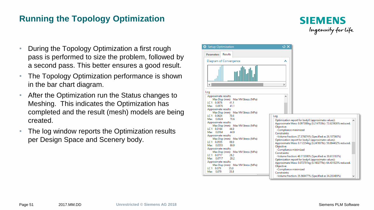
Running the Topology Optimization
• During the Topology Optimization a first rough
pass is performed to size the problem, followed by
a second pass. This better ensures a good result.
• The Topology Optimization performance is shown
in the bar chart diagram.
• After the Optimization run the Status changes to
Meshing. This indicates the Optimization has
completed and the result (mesh) models are being
created.
• The log window reports the Optimization results
per Design Space and Scenery body.

Unrestricted © Siemens AG 20182017.MM.DDPage 52 Siemens PLM Software
Geometry Results
For each Design Space and Scenery body there will be 3 faceted models.
User can use the normal NX display options to control what they want to view.
Optimization results are stored as Attributes on the body
Geometry Displacement Von Mises Stress
Unrestricted © Siemens AG 20182017.MM.DDPage 53 Siemens PLM Software
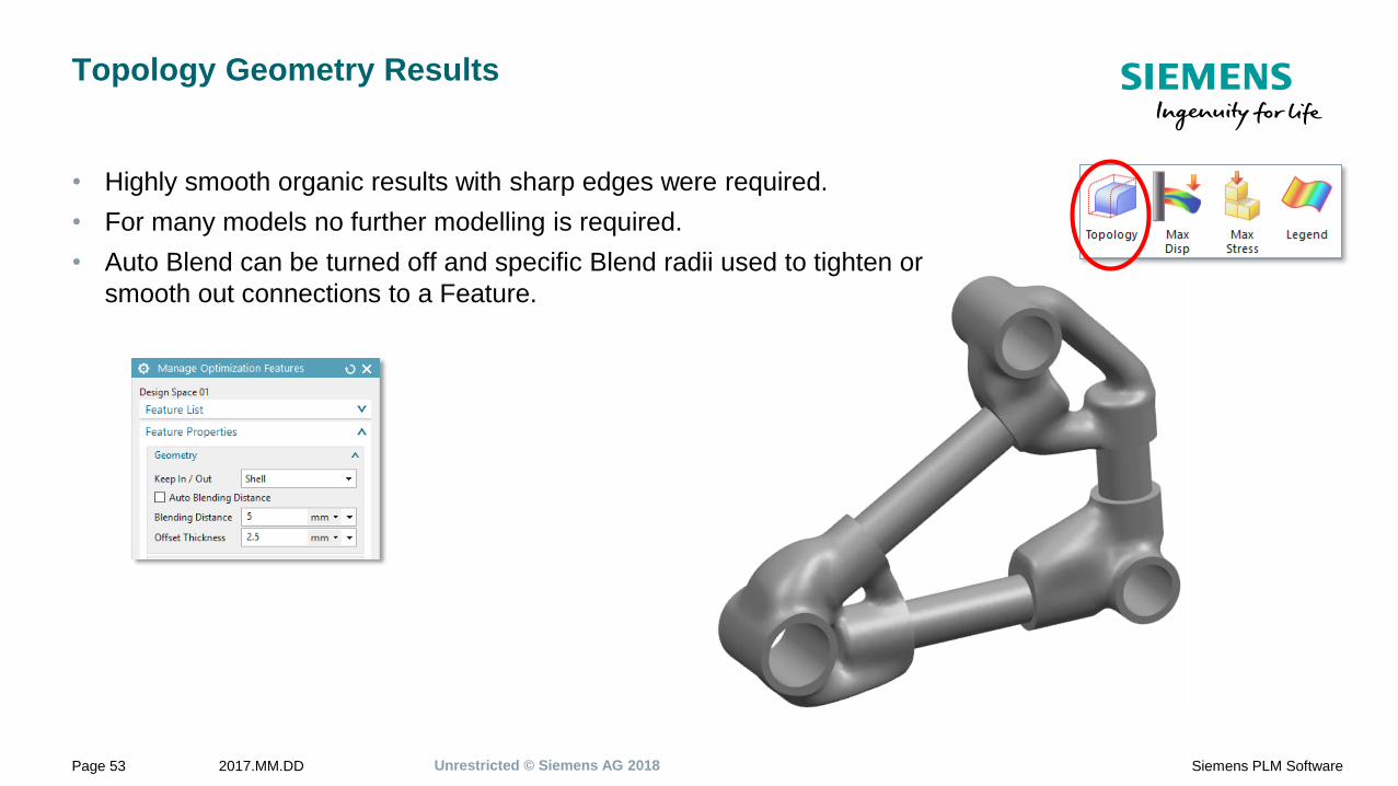
Topology Geometry Results
• Highly smooth organic results with sharp edges were required.
• For many models no further modelling is required.
• Auto Blend can be turned off and specific Blend radii used to tighten or
smooth out connections to a Feature.

Unrestricted © Siemens AG 20182017.MM.DDPage 54 Siemens PLM Software
Displacement Results
The Displacement (magnitude) results are available for each Design Space
and Scenery body.
The results shown are the max values envelope across all the load cases.
The results are quantitatively good and can confidently be used to guide
design decisions.
Unrestricted © Siemens AG 20182017.MM.DDPage 55 Siemens PLM Software
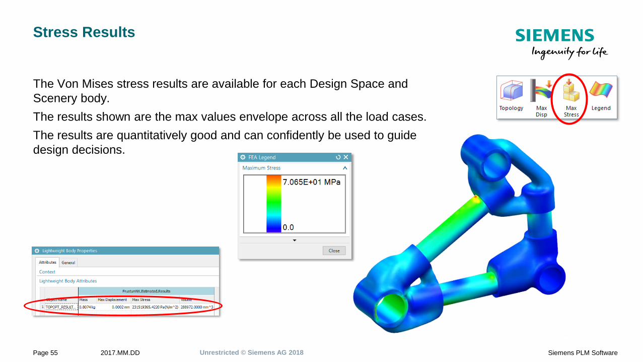
Stress Results
The Von Mises stress results are available for each Design Space and
Scenery body.
The results shown are the max values envelope across all the load cases.
The results are quantitatively good and can confidently be used to guide
design decisions.

Unrestricted © Siemens AG 20182017.MM.DDPage 56 Siemens PLM Software
Natural Frequency Results
This analysis type shows just the optimized
geometry, and the Mass, Volume and Frequencies
obtained.
The results are quantitatively good and can
confidently be used to guide design decisions.

Unrestricted © Siemens AG 20182017.MM.DDPage 57 Siemens PLM Software
Roadmap
1. Exploring design options based on known functional requirements.
• NX Topology Optimization for Designers.
• Move current NX Open implementation into
NX Core
• More functionality
• Connection types
• Design constraints
• User selected optimization objective
and constraints
• Enable remote solves
• Include Lattice creation
• Multiple results management
• Streamline FE setup transfer to Simcenter for validation of result runs

Unrestricted © Siemens AG 20182017.MM.DDPage 58 Siemens PLM Software
Uses for the Topology Optimization Results
Topology Optimization is not the finish, for many parts it’s
just the start. Many opportunities exist to use the
Topology Optimization results.
1. Direct to AM machine for printing.
2. Direct to cast, mold or multi-axis machining.
3. Use for further Design or Simulation using Convergent
models.
4. Guidance for re-modelling using traditional CAD tools.
Holes cut into Convergent Facet model
Unrestricted © Siemens AG 20182017.MM.DDPage 59 Siemens PLM Software
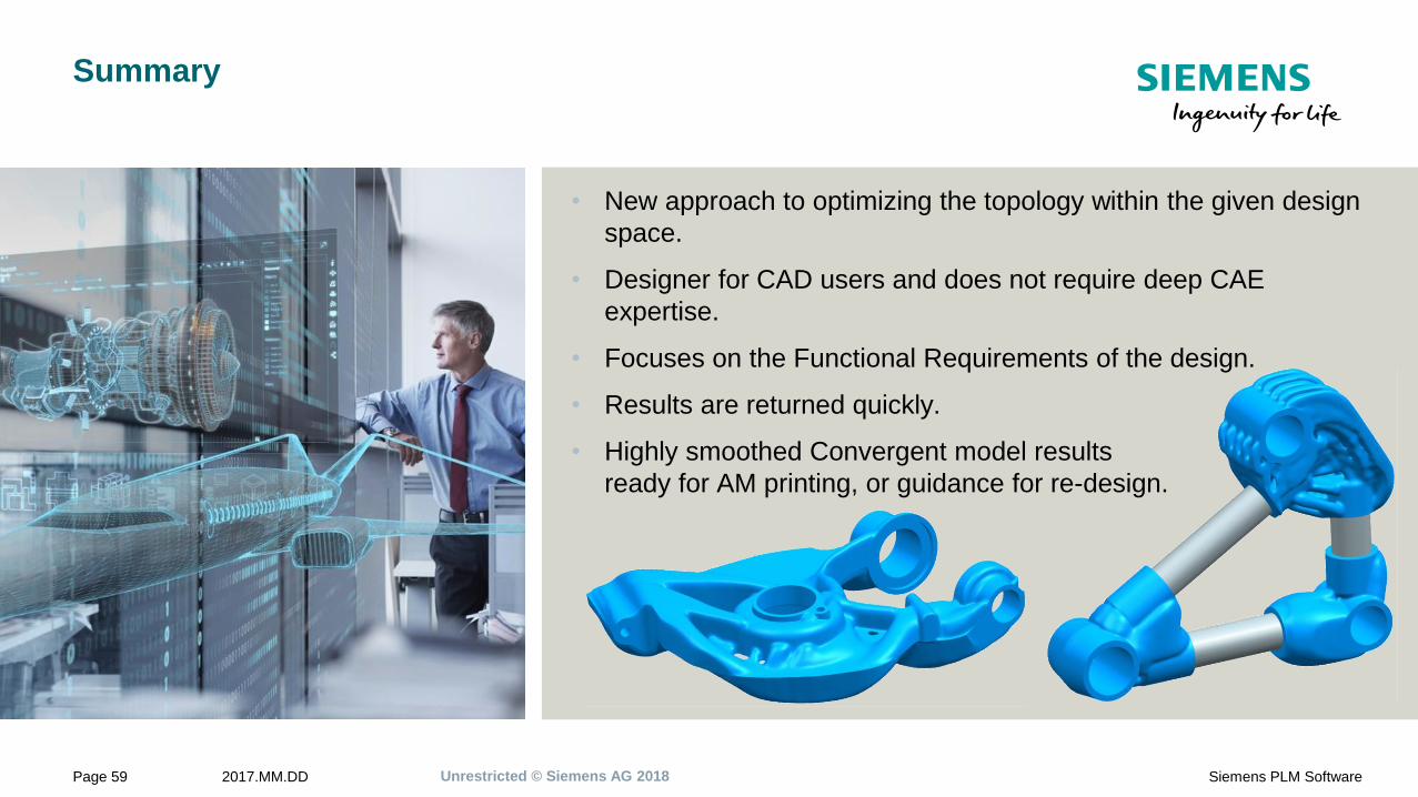
Summary
• New approach to optimizing the topology within the given design
space.
• Designer for CAD users and does not require deep CAE
expertise.
• Focuses on the Functional Requirements of the design.
• Results are returned quickly.
• Highly smoothed Convergent model results
ready for AM printing, or guidance for re-design.

Guy WillsProduct Manager
Simcenter 3D Engineering Desktop
E-mail:
Realize innovation.