of the new offset type parabolic concentrator with …
TRANSCRIPT

FACTA UNIVERSITATIS Series: Mechanical Engineering Vol. 13, No 2, 2015, pp. 169 - 180
OPTICAL MODEL AND NUMERICAL SIMULATION
OF THE NEW OFFSET TYPE PARABOLIC CONCENTRATOR
WITH TWO TYPES OF SOLAR RECEIVERS
UDC 535.2; 536.2; 536.6; 536.7
Saša Pavlović1, Darko Vasiljević
2, Velimir Stefanović
1,
Zoran Stamenković1, Sadoon Ayed
3
1Faculty of Mechanical Engineering, University of Niš, Serbia
2Institute of Physics, Photonics Center, University of Belgrade, Serbia
3University of Technology, Department of Mechanical Engineering, Baghdad, Iraq
Abstract. The paper presents a physical and mathematical model of the new offset type
parabolic concentrator and a numerical procedure for predicting its optical performances.
Also presented is the process of design and optical ray tracing analysis of a low cost solar
concentrator for medium temperature applications. This study develops and applies a new
mathematical model for estimating the intercept factor of the solar concentrator based on its
geometrical and optical behavior. The solar concentrating system consists of three offset
parabolic dish reflectors and a solar thermal absorber at the focus. Two types of absorbers
are discussed. One is a flat plate circular absorber and the other a spiral smooth pipe
absorber. The simulation results could serve as a useful reference for design and
optimization of offset parabolic concentrators.
Key Words: Optical Modeling, Parabolic Offset Reflector, Solar Energy, Ray Tracing
Methodology, Geometric Factors, Characteristics of Concentration.
1. INTRODUCTION
Solar energy is one of the alternative sources that can meet energy demands. This
form of energy can be harnessed at a comparatively low cost. The device which is used to
transform solar into heat energy is referred to as a solar thermal collector or STC.
Depending on the temperatures gained by them, STCs can be divided into low, middle
and high temperature systems. Mid-temperature systems are applicable for refrigeration
systems and industrial processes. Among several types of solar concentrators, the multi-
dish concentrator consisting of several discrete small dishes arouses wide interest. They
Received June 28, 2015 / Accepted July 29, 2015Corresponding author: Saša Pavlović
Faculty of Mechanical Engineering, University of Nis, Aleksandra Medvedeva 14, 18000 Niš, Serbia
E-mail:[email protected]
Original scientific paper
170 S. PAVLOVIĆ, D. VASILJEVIĆ, V. STEFANOVIĆ, Z. STAMENKOVIĆ, S. AYED
are convenient for manufacturing, installation and mending discrete dishes. To avoid
design complexity of a specific shaped surface solar concentrator, a common offset
parabolic antenna is used to make the solar reflector. These types of antennas are widely
used both in developed and underdeveloped countries and they are cheap and easy to obtain.
A configuration with several offset parabolic antennas offers many advantages over most
common centered-focus solar parabolic concentrators (focal point concentrators), like lower
wind resistance and higher stability of the structure because of a lower center of gravity.
Munir [1] presented an experimental study of transforming solar energy into thermal
energy by using a parabolic solar concentrator with a system of continual tracking of the
sun. The experiment was carried out on a prototype of concentrator of 1 m in diameter
and a copper receiver, 10 cm in diameter and 20 cm length. The receiver was located at the
focal plane of the parabola. This model of parabolic solar concentrator led to the levels of
temperatures ranging between 2000C and 350
0C.
Bellel [2] studied the difference in performance of two types of solar cylindrical
receivers. Bellel dealt particularly with problems of heat transfer in the absorber. In fact,
the concentration of solar energy, which the absorber converts into thermal energy, allows
one to meet various needs: hot water for different uses, production of electricity through the
generation of steam, sterilization of objects (medical devices). Bhirud and Tandale [3] and
Delaney [4] developed concentrators that are capable of delivering temperatures in the
range of 3000C and are technically suitable for medium temperature applications. With a
higher concentration ratio, there is an increase in temperature at which heat is delivered. It
is observed from the comparison that the two axes tracking paraboloidal dish, which always
faces the sun, is the most promising design for the concentrating systems justifying the use
of the Scheffler concentrator for industrial process heat applications. These concentrators
also provide an automatic tracking system. Scheffler [5] has shown that about half of the
power of sunlight which is collected by the reflector becomes finally available in the
cooking vessel. The use of solar energy for the generation of steam is now an economically
attractive possibility since the payback period of such a system lies between 1.5 and 2 years.
Ruelas et al. [6] developed and applied a new mathematical model for estimating the intercept
factor of a Scheffler-type solar concentrator (STSC) based on the geometric and optical
behavior of the concentrator in Cartesian coordinates. Reinalter et al. [7] investigated thermal
and geometric features of the 10 kW receiver CNRS-PROMES system (parabolic reflector
with diameter 3.8m, focal length 4.5m). The validation process of the thermal model was
performed by comparing the experimental results reported for the 10 kW cavity receiver
CNRS-PROMES system to the results obtained from the simulation of incoming solar
radiation in laboratory conditions by using a solar simulator. Munir et al. [8] showed the
design principle and calculation of a Scheffler fixed focus concentrator with the surface area
of 8 m2 for medium temperature applications. The authors proved mathematically that it is
possible to construct a concentrator that can provide a fixed focus for each day in a year.
Bugarin [9] presented the process of design and construction of a low-cost solar concentrator
for cooking. This type of solar cooker produces vertically reflected rays that reach the food pot
at the bottom like in conventional stoves. Rapp and Schwartz [10] constructed and
successfully tested a 2m2 parabolic dish solar concentrator (Scheffler Concentrator) to focus
sunlight onto a stationary target. They described some ideas about the intricate design of
the Scheffler reflectors and how they are developed. The parabolic Scheffler reflectors
can provide for a high temperature heat for all types of cooking, steam generation and many
Optical Model and Numerical Simulation of New Offset Type Parabolic Concentrator... 171
other applications. Macosko et al. [11] described a solar concentrator system designed to
supply both thermal and electrical energy to a hydrogen reduction reactor modeled after
the NASA Roxygen first generation system. A concept is defined that utilizes an offset
parabolic concentrator to collect and focus solar energy directly into the Roxygen reactor.
The offset parabolic concentrator was rotated to track the sun. A two axis solar tracking
system and a concentrator positioning system were utilized to keep the concentrator
perfectly aligned with the sun and the focal point centered at the reactor (receiver) aperture.
Asmelash et al. [12] also designed and manufactured an offset type of solar concentrating
system for cooking purposes. The concentrating offset collector had major and minor
diameters of 90 by 80 cm respectively. The system was tested for its thermal performance
following standard testing procedures of the American Society of Agricultural Engineers
(ASAE) and it was found useful with an encouraging results. Maximum temperature of
9400C was achieved in the cooking vessel after 25 minutes. Patil et al. [13] investigated
convection heat loss that inevitably occurs in receivers with high concentrating solar
concentrators. They presented an experimental investigation of natural convection heat loss
from the hemispherical cavity receiver with diameter 540 mm. The aim of the project was
to develop the setup that may be used to identify the total heat loss and convective heat loss
from the receiver. Cabanillas and Kopp [14] developed a solar parabolic dish concentrator
with a diameter of 2.44 mm and focal length of 0.92 m. They studied a solar spiral heat
exchanger made from carbon steel in order to measure the energy efficiency and net energy
gain of the concentration system. Saravanan et al. [15] designed solar biomass hybrid dryer
for the purpose of drying 40 kg of cashew nut per batch. They have investigated the thermal
performance of a solar biomass dryer. Their system consists of a solar flat plate collector, a
biomass heater, a drying unit, a blower and a chimney. The solar air heating collector
system consists of an absorber, a double glass cover, a back plate and insulation. The offset parabolic reflectors are more efficient since objects placed at the focus do not
create shadows over the reflecting surface. This paper also describes a prototype of an offset parabolic dish with 2400 mm in diameter. The system consists of three identical offset satellite dishes that are positioned in such a way that they concentrate sun radiation in the integral focal area with the desired area and geometry. This study develops and applies a new mathematical model for estimating the intercept factor of the solar concentrator based on its geometrical and optical behavior. This paper, however, does not devote much attention to experimental measurement and testing of thermal performance of the concentrating solar collectors. As a next step in the research, the experimental verification of simulated results is planned.
2. DESCRIPTION OF THE LOW-COST PARABOLIC OFFSET CONCENTRATING COLLECTOR FOR
THERMAL APPLICATION
Fig. 1 shows a parabolic offset solar concentrator system installed in the Laboratory for Thermal Engineering at the Faculty of Mechanical Engineering, University of Niš. The system consists of three identical offset satellite dishes that are positioned in such a way that they concentrate sun radiation in the integral focal area. The inner surface of the offset parabolic dishes that faces the sun is covered with aluminum foil. The reflectivity of the foil ranges from 58 to 60%. The reflective foil should be cut in such a way that there are no wrinkles when they are glued to the surface of the dish; hence 10 cm wide rectangular

172 S. PAVLOVIĆ, D. VASILJEVIĆ, V. STEFANOVIĆ, Z. STAMENKOVIĆ, S. AYED
pieces are the optimum cut size for the offset parabolic dish. The concentration of solar radiation in a spiral absorber – receiver (focus surface area) is shown in Fig. 2.
Fig. 1 Experimental model of a parabolic
offset solar concentrator system
Fig. 2 Concentration of solar radiation at
the spiral absorber pipe
Fig. 3 Infrared image of the coil receiver taken at 15:05 pm on September, 30, 2014
Fig. 3 shows an infrared image of the coil receiver. The maximum measured surface
temperature was 335 C. The day was clear and sunny. The measurement was performed with
the thermal imaging camera FLIR E30. It was expected that the temperature at the coil
receiver would be about 400 C in July or August.
2.1. Physical model of the offset type parabolic dish concentrator
with a thermal spiral tube absorber
The offset solar parabolic concentrator is the result of the interception of the open circular
area with a small side section of the parabola. It directs solar radiation to a fixed focus point
where a solar absorber - receiver is installed and secured by a fixed support structure.
Optical Model and Numerical Simulation of New Offset Type Parabolic Concentrator... 173
It was made from low carbon manganese steel. The support structure of the offset solar
parabolic dish concentrator was made by welding a large number of metal profiles with a
square cross-section (0.03 0.03m). Parabolic offset reflectors were placed on the support
structure by using adequate trusses which enabled the reflectors to be dismantled from the
support structure at any given moment. Adjustment of the elevation angle of each of three
offset reflectors is possible in the range from 0 to 30 relative to the horizontal plane of the
support structure.
The mechanical structure should allow the positioning of the three parabolic offset
reflectors into the optimal position in which solar rays strike the solar concentrator at angle
of 90. The authors performed several numerical simulations of dynamic loads for various
wind speeds and angle of attack. The system was designed in the following way. The
reflectors track the sun up to the wind speed of vw = 20m/s. At greater speeds, the system
stops tracking the sun and gets itself into the most stable position which is the horizontal
one. The system was designed with the applied CAD technologies and calculated to
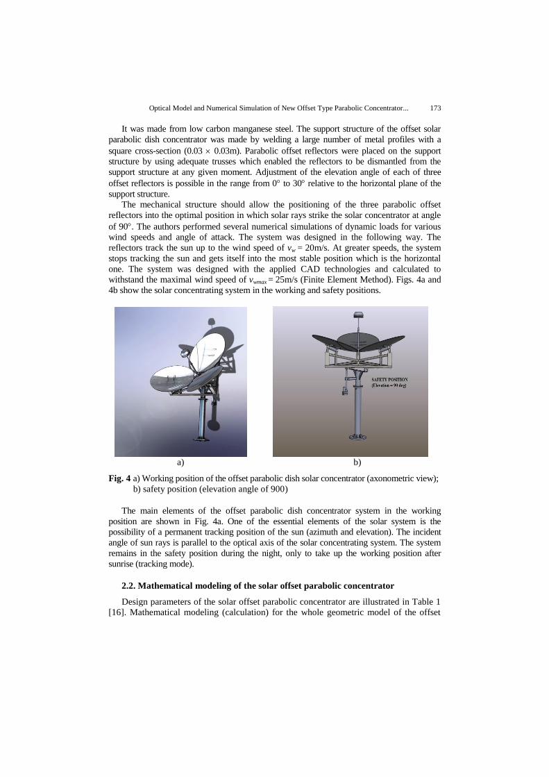
withstand the maximal wind speed of vwmax = 25m/s (Finite Element Method). Figs. 4a and
4b show the solar concentrating system in the working and safety positions.
a) b)
Fig. 4 a) Working position of the offset parabolic dish solar concentrator (axonometric view);
b) safety position (elevation angle of 900)
The main elements of the offset parabolic dish concentrator system in the working
position are shown in Fig. 4a. One of the essential elements of the solar system is the
possibility of a permanent tracking position of the sun (azimuth and elevation). The incident
angle of sun rays is parallel to the optical axis of the solar concentrating system. The system
remains in the safety position during the night, only to take up the working position after
sunrise (tracking mode).
2.2. Mathematical modeling of the solar offset parabolic concentrator
Design parameters of the solar offset parabolic concentrator are illustrated in Table 1
[16]. Mathematical modeling (calculation) for the whole geometric model of the offset

174 S. PAVLOVIĆ, D. VASILJEVIĆ, V. STEFANOVIĆ, Z. STAMENKOVIĆ, S. AYED
parabolic concentrator was done in Wolfram Mathematica v.8.0. The numerical solution
of the mathematical model was used to obtain geometric parameters such as the radius of
the smaller and larger semi axis of the ellipse, the focal length, and the tangent slope for
the three offset reflectors. Parameters obtained from mathematical analysis were used as
input parameters for 3D modeling in the CAD program CATIA V5R19 - Dassault
Systems, USA. The first step was to design a rotational paraboloid with diameter D =
5000 mm and focal length f = 1600 mm. The next step was to design a circular cylinder
with diameter D = 1100 mm, which was positioned parallel to the optical axis of the
rotational paraboloid at the distance of 100 mm from the optical axis. The three cylinders
were positioned parallel to the optical axis and the angle between the axes of the cylinders
was 120°. Unlike a conventional paraboloid concentrator, the offset parabolic concentrator
system fixed focus concentrator is a lateral part of a paraboloid as shown in Fig. 5a. Fig. 6
shows the structure and geometric model of the new type of solar offset parabolic
concentrator. The choice of the optimal position of the solar thermal absorber – receiver
was carried out on the basis of Monte Carlo ray tracing analysis model of the offset type
parabolic concentrator dish and receiver. The optimal focal distance is 1155 mm, while the
theoretical focal distance is 1600 mm - focal hot spot.
PARABOLOID
Available
aperture
area
Lateral section of
a paraboloid
(Offset parabolic
concentrator)
FOCUS
Beamsolarradiation
DIRECTRIX
VERTEX
Y
X
1100 mm
2500 mm
a) b)
Fig. 5 a) Section of the offset parabolic solar dish concentrator from baseline paraboloid;
b) Process of determining a offset parabolic solar dish concentrator
The mathematical representation of the parabolic concentrator is paraboloid which can be
represented as a surface obtained by rotating the parabola around the axis. Mathematical
equations for the parabolic dish solar concentrator in Cartesian coordinate systems are
defined as:
fzyx 422 (1)

Optical Model and Numerical Simulation of New Offset Type Parabolic Concentrator... 175
Table 1 Geometric parameters of the offset parabolic dish concentrator, Pavlovic et al. [16]
Design parameter Numerical value Unit
Major diameter of reflector Dref 1.20 [m]
Minor diameter of reflector Dref 1.10 [m]
Cross-section of opening offset parabolic concentrator Aproj 5.31 [m2]
Sheltered area of concentrator Ashadow 0 [m2]
Effective area of offset concentrator Aap,ref 2.85 [m2]
Receiver diameter 0.20 [m]
Diameter of baseline paraboloid 5 [m]
Depth of baseline paraboloid 0.98 [m]
Depth of offset parabolic concentrator 0.33 [m]
Focal length 1.6 [m]
ψ1 - rim angle 43.15 [0]
Absorber area 0.0314 [m2]
Geometric concentration ratio CRg = Aap/Arec 96.01 [-]
Optical (flux) concentration ratio CR0 = Irec/ Iap= Irec /DNI 87,07 [-]
Surface reflectance ρ 0.60 [-]
Direct solar radiation Id 800 W/m2
a) b)
Fig. 6 a) Structure of the new type of solar offset parabolic concentrator;
b) Geometrical model of the new type of solar offset parabolic concentrator
Usually the paraboloids that are used in solar collectors have rim angles from 10 to 90
degrees. The relationship between the relative aperture and the rim angle is given by:
)2/tan(4
1/
rim
Df
(2)
Intercept factor φ represents the fraction of the radiation intercepted by the cavity receiver
and is calculated by Eq. (3) with a change over the term of the fraction of the captured
flux, using Γ1.975
instead of Γ.
The shadow produced by the receiver was considered as a dead area on the projected
area of dish reflective surface Adish. Power consumption for the tracking and controlling
systems were neglected.

176 S. PAVLOVIĆ, D. VASILJEVIĆ, V. STEFANOVIĆ, Z. STAMENKOVIĆ, S. AYED
1.975
0
8 sin( )
dish
If
IA
(3)
The incident energy received by solar spiral absorber of offset parabolic dish concentrator
can be computed from the following equation:
( )s b eQ I C (4)
The optical efficiency of that solar concentrator can be computed from:
0 ( )c e (5)
3. PHYSICAL MODELS OF TWO TYPES OF SOLAR SPIRAL THERMAL RECEIVERS
In terms of their configuration, receivers can be flat receivers or cavity receivers. The
first ones focal absorber surfaces, whilst the latter ones have the absorber surface
surrounded by an insulated cover, with a sufficient opening to capture the radiation from
the concentrator. The shape of the receiver depends on its dimension and the concentrator
focal length/rim angle. Photo thermal conversion in a dish cavity receiver is a key process
to efficiently utilize solar energy, mainly because the cavity receiver converts the
collected solar radiation into thermal energy by coupling the complicated heat transfer.
This paper analyzes two types of solar thermal receivers presented in Fig. 7. The first
type is the solar thermal receiver with a flat plate. The receiver is a metal disc painted
black. The second type is the Archimedean spiral smooth pipe directly exposed to
reflected radiation from the offset dish concentrator.
The receptor portion of the heat exchanger has three primary components, all made of
stainless steel. The spiral pipe absorber creates a spiral path for fluid to flow through.
a) b)
Fig. 7 Two types of solar thermal receivers: a) flat plate painted black; b) spiral pipe
The flow rates in spiral absorber pipe are changeable data. The next step is to create an experimental installation in the Mechanical Engineering Laboratory for testing and thermal hydraulic performance of said heat exchangers in stationary conditions. The
Optical Model and Numerical Simulation of New Offset Type Parabolic Concentrator... 177
installations will be able simulations of real solar modules (offset parabolic concentrator). They will serve as the basis for investigating the work of the spiral absorber at different geometric and spatial configurations, fluid flow, heat input levels, as well as the fluids with significantly different thermo-physical properties (water and a solution of propylene glycol). In order to assess the efficiency of the heat exchanger the measurement of thermal and hydraulic losses will be carried out.
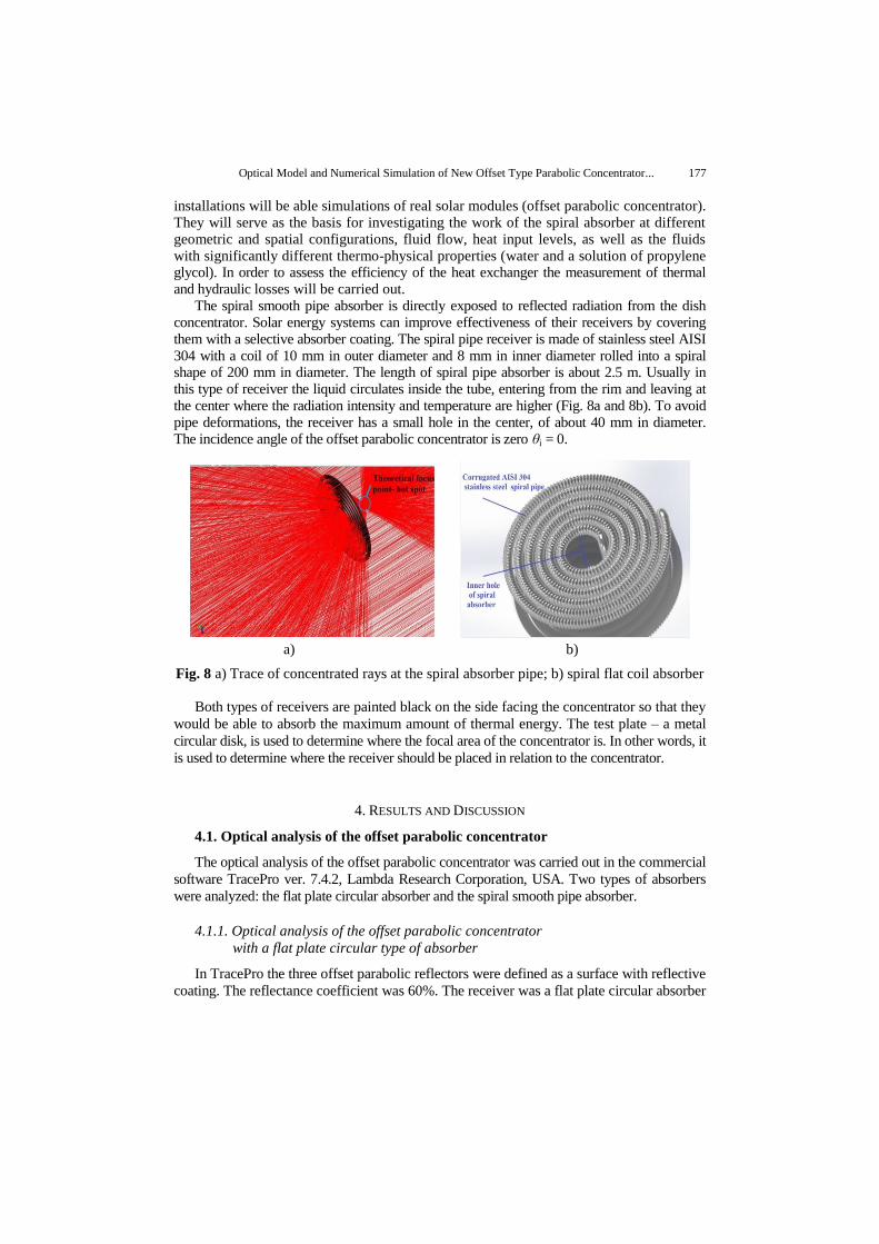
The spiral smooth pipe absorber is directly exposed to reflected radiation from the dish concentrator. Solar energy systems can improve effectiveness of their receivers by covering them with a selective absorber coating. The spiral pipe receiver is made of stainless steel AISI 304 with a coil of 10 mm in outer diameter and 8 mm in inner diameter rolled into a spiral shape of 200 mm in diameter. The length of spiral pipe absorber is about 2.5 m. Usually in this type of receiver the liquid circulates inside the tube, entering from the rim and leaving at the center where the radiation intensity and temperature are higher (Fig. 8a and 8b). To avoid pipe deformations, the receiver has a small hole in the center, of about 40 mm in diameter. The incidence angle of the offset parabolic concentrator is zero θi = 0.
a) b)
Fig. 8 a) Trace of concentrated rays at the spiral absorber pipe; b) spiral flat coil absorber
Both types of receivers are painted black on the side facing the concentrator so that they
would be able to absorb the maximum amount of thermal energy. The test plate – a metal
circular disk, is used to determine where the focal area of the concentrator is. In other words, it
is used to determine where the receiver should be placed in relation to the concentrator.
4. RESULTS AND DISCUSSION
4.1. Optical analysis of the offset parabolic concentrator
The optical analysis of the offset parabolic concentrator was carried out in the commercial
software TracePro ver. 7.4.2, Lambda Research Corporation, USA. Two types of absorbers
were analyzed: the flat plate circular absorber and the spiral smooth pipe absorber.
4.1.1. Optical analysis of the offset parabolic concentrator
with a flat plate circular type of absorber
In TracePro the three offset parabolic reflectors were defined as a surface with reflective
coating. The reflectance coefficient was 60%. The receiver was a flat plate circular absorber

178 S. PAVLOVIĆ, D. VASILJEVIĆ, V. STEFANOVIĆ, Z. STAMENKOVIĆ, S. AYED
with the diameter of 200 mm and 5 mm in thickness. The absorbing surface was defined as
the perfect absorber (α =1). The position of the receiver was found by calculating the
optimal flux for the given receiver. The optimal position was found at 1155 mm from the
vertex of the parabolic dish, after several calculations in TracePro. At a distance of
1155 mm the best value of total flux was obtained - solar power and irradiance flux density
distribution. After defining the geometry of the offset parabolic solar concentrator, the
radiation source was defined. The radiation source was circular with the same diameter as
that of the parabolic dish (2400 mm). The radiation source was placed 1500 mm from the
vertex of the offset solar parabolic concentrator and had a circular grid pattern for the
Monte Carlo ray tracing. The spatial profile of generated rays was uniform and the angular
profile was solar radiation. The input parameter for the optical analysis was the solar
irradiance which was set to 800 W/m2. Experimental values for solar irradiation for the
City of Niš in Serbia are between 750 W/m2 and 900 W/m
2. The optical system for the offset
parabolic solar concentrator with traced rays is given in Fig. 9. Since the offset parabolic
concentrator continually tracked the sun, the incidence angle of solar rays was always
θ = 00 . For this type of solar concentrator cosine losses do not exist.
X
Y
ZZ
Fig. 9 Ray tracing model of the offset
parabolic solar concentrator with
the flat plate circular absorber
Fig. 10 Solar flux distribution
on the absorber surface
The optical analysis was done by generating 119401 rays and calculating them by the
Monte Carlo ray trace. From all the emitted rays only 76058 rays reached the absorber
surface, which was 64% of the emitted rays. The calculated irradiance for the absorbed
rays on the receiver was from 3.88∙10-9
W/m2 to 3.25∙10
5 W/m
2. The total calculated flux
on the flat plate receiver was 2188 W. Fig. 10 shows the total irradiance map for the
absorbed flux on the receiver.
4.1.2. Optical analysis of the offset parabolic concentrator
with a spiral smooth pipe absorber
The second optical analysis was performed on the more complicated model of the
solar absorber. The solar absorber was the spiral pipe absorber described in the previous
section. The position of the receiver was found by calculating the optimal flux for the
Optical Model and Numerical Simulation of New Offset Type Parabolic Concentrator... 179
given receiver. The optimal position of the receiver was 1155 mm from the vertex of the
parabolic dish.
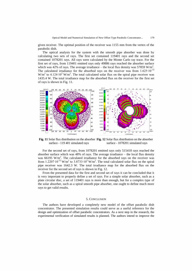
The optical analysis for the system with the smooth pipe absorber was done by
calculating two sets of rays. The first set contained 119401 rays and the second set
contained 1078201 rays. All rays were calculated by the Monte Carlo ray trace. For the
first set of rays, from 119401 emitted rays only 49886 rays reached the absorber surface
which was 42% of rays. The average irradiance – the local flux density was 57859 W/m2.
The calculated irradiance for the absorbed rays on the receiver was from 1.625∙10-15
W/m2 to 4.124∙10
5 W/m
2. The total calculated solar flux on the spiral pipe receiver was
1435.4 W. The total irradiance map for the absorbed flux on the receiver for the first set
of rays is shown in Fig. 11.
Fig. 11 Solar flux distribution on the absorber
surface - 119 401 simulated rays
Fig. 12 Solar flux distribution on the absorber
surface - 1078201 simulated rays
For the second set of rays, from 1078201 emitted rays only 515418 rays reached the
absorber surface which was 48% of rays. The average irradiance – the local flux density
was 66195 W/m2. The calculated irradiance for the absorbed rays on the receiver was
from 1.2207∙10-15
W/m2 to 3.8733∙10
5 W/m
2. The total calculated solar flux on the spiral
pipe receiver was 1642.3 W. The total irradiance map for the absorbed flux on the
receiver for the second set of rays is shown in Fig. 12.
From the presented data for the first and second set of rays it can be concluded that it
is very important to properly define a set of rays. For a simple solar absorber, such as a
plate circular disc, a set of 119401 rays is more than enough, but for a complex type of
the solar absorber, such as a spiral smooth pipe absorber, one ought to define much more
rays to get valid results.
5. CONCLUSION
The authors have developed a completely new model of the offset parabolic dish
concentrator. The presented simulation results could serve as a useful reference for the
design and optimization of offset parabolic concentrators. As a next step in the research, the
experimental verification of simulated results is planned. The authors intend to improve the

180 S. PAVLOVIĆ, D. VASILJEVIĆ, V. STEFANOVIĆ, Z. STAMENKOVIĆ, S. AYED
design of the absorber by developing a solar receiver with a cavity. This type of receiver has
significantly smaller convective and radiation losses and greater conversion efficiency of
solar radiation to heat.
Acknowledgements: The paper is a part of the research done within the projects: III 42006-
Research and development of energy and environmentally highly effective polygeneration systems
based on renewable energy resources and III 45016 - Fabrication and characterization of nano-
photonic functional structures in biomedicine and informatics. Both projects are financed by the
Ministry of Education, Science and Technological Development of the Republic of Serbia. The
authors would like to acknowledge the help provided by the Lambda Research Corporation by
allowing the use of TracePro software for the PhD research of Saša Pavlović.
REFERENCES
1. Munir A., 2010, Design, development and modeling of a solar distillation system for the processing of
medicinal and aromatic plants, PhD Thesis, Universität Kassel/Witzenhausen, Germany 173 p. 2. Bellel N., 2011, Study of two types of cylindrical absorber of a spherical concentrator, Energy Procedia,
6, pp. 217–227.
3. Bhirud N., Tandale S., 2006, Field evaluation of a fixed-focus concentrators for industrial oven, In: Proceedings of National Conference on Advances in Energy Research, December, IIT - Bombay, India,
pp. 364–370.
4. Delaney D., 2003, Scheffler’s community solar cooker, http://www.solar-bruecke.org. (last access: 04.04.2015.) 5. Scheffler W., 2006, Introduction to the revolutionary design of Scheffler, http://www.solare-bruecke.org.,
Proceedings of SCIs International Solar Cooker Conference, Granada, Spain
6. Ruelas Ј., Pando G., Baldomero L and Tzab J., 2014, Ray Tracing Study to Determine the Characteristics of the Solar Image in the Receiver for a Scheffler-Type Solar, Energy Procedia, 57, ISES Solar World Congress, pp.
2858-2866.
7. Reinalter W., Ulmer S., Heller P., Rauch T., Gineste J., Ferriere A., Nepveu F., 2008, Detailed performance analysis of the 10 kW dish/Stirling system, Journal of Solar Energy Engineering.
8. Munir A., Hensel O., Sheffler W., 2010, Design principle and calculations of a Scheffler fixed focus,
Solar Energy, 84(8), pp. 1490–1502. 9. Bugarin D., 2011, Design and construction of a low cost offset parabolic solar concentrator for solar
cooking in rural areas, Proceedings of ISES Solar World Congress, Kassel, Germany, Depertment of
Electronics, IES Escolas Proval, Galicia, Spain. 10. Rapp J., Schwartz P., 2010, Construction and Improvement of a Scheffler Reflector and Thermal Storage
Device, Cal Poly Physics Insitute, California Polytechnic State University, San Luis Obispo, California,
USA, http://www.physics.calpoly.edu. 11. Macosko R., Colozza A., Castle C., 2010, Solar Concentrator Concept for Providing Direct Solar
Energy for Oxygen Production at the Lunar South Pole, Proceedings of 48th AIAA Aerospace Sciences
Meeting Including the New Horizons Forum and Aerospace Exposition, Orlando, Florida, USA 12. Asmelash H., Kebedom A., Bayray M., Mustofa A., 2014, Performance Investigation of Offset Parabolic
Solar Cooker for Rural Appplications, International Journal of Engineering Research & Technology,
3(12), pp. 2278-0181.
13. Patil M., Jahagirdar R., Deore E., 2012, Experimental investigation of heat loss from hemispherical solar
concentrator receiver, Frontiers in Heat and Mass Transfer, 3, DOI (10.5098/hmt.v3.3.3008).
14. Cabanillas E., Kopp J., 2007, Measuring energy efficiency from a 4 kW dish concentrator system using older parabolic antenna technology, Proceedings of ISES, Solar World Congress, Orlando, Florida. (Vol. I – Vol. V),
pp. 726-730, http://link.springer.com.
15. Saravanan D., Wilson V., Kumarasamy S., 2014, Design and thermal performance of the solar biomass hybrid dryer for cashew drying, Facta Univesitatis, Series: Mechanical Engineering, 12(3), pp. 277-288.
16. Pavlovic S., Stefanovic V., Mancic M., Spasic Z., 2015, Development of mathematical model of offset type solar
parabolic concentrating collector, Proceedings of 12th International Conference on Accomplishments in Electrical and Mechanical Engineering and Information Technology, Faculty of Mechanical Engineering, Banja
Luka, Bosnia and Herzegovina.