oip transformer outdoor bushings type cot(c) 125…cot (c ... · bushing proven in operation...
TRANSCRIPT

OIP Transformer Outdoor BushingsType COT(C) 125…COT (C) 180024kV to 550kVup to 3150AIEC 60137-2008

Page 2 / 24 40497230_00 Substitute for E 322.81&E 322.91
Features
available with porcelain or composite insulator on air side
inclination in service up to 30° from vertical. For COT(C) 125 and COT(C) 170 even horizontal operation is possible
horizontal transport for all types possible
tan α and PD-values more than twice as good as requested by IEC 60137
current rating can easily be increased by exchanging the cable bolt with a removable split conductor on existing bushing
experience in manufacturing of bushings for more than 100 years
capacitive fine graded oil-paper insulation with long experience
computer optimized electrical field distribution
proven high electrical withstand against transient or impulse stresses
excellent long term stability due to extremely low partial discharge and power loss factor
oil immersed part covered by epoxy resin tube providing high impact resistance
electrode embedded in the lower epoxy resin part - avoids external shielding - reduces distance to ground - lower transformer costs
porcelain cemented into flange provides higher mechanical strength than level II of IEC
If you need any transformer bushing proven in operation conditions around the world,
Trench has it !
To preserve our environment the free oil
volume in COT-bushings is minimized
Certified ISO 9001
Transformer Bushings Type COT(C) 125 to COT(C) 1800
40497230_04
Page 3 / 24 40497230_00 Substitute for E 322.81&E 322.91
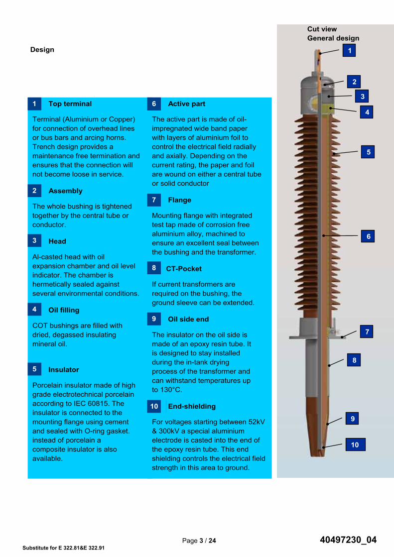
Design
Cut view General design
10
Top terminal
Terminal (Aluminium or Copper) for connection of overhead lines or bus bars and arcing horns. Trench design provides a maintenance free termination and ensures that the connection will not become loose in service.
Assembly
The whole bushing is tightened together by the central tube or conductor.
Head
Al-casted head with oil expansion chamber and oil level indicator. The chamber is hermetically sealed against several environmental conditions.
Oil filling
COT bushings are filled with dried, degassed insulating mineral oil.
Insulator
Porcelain insulator made of high grade electrotechnical porcelain according to IEC 60815. The insulator is connected to the mounting flange using cement and sealed with O-ring gasket. instead of porcelain a composite insulator is also available.
Active part
The active part is made of oil- impregnated wide band paper with layers of aluminium foil to control the electrical field radially and axially. Depending on the current rating, the paper and foil are wound on either a central tube or solid conductor
Flange
Mounting flange with integrated test tap made of corrosion free aluminium alloy, machined to ensure an excellent seal between the bushing and the transformer.
CT-Pocket
If current transformers are required on the bushing, the ground sleeve can be extended.
Oil side end
The insulator on the oil side is made of an epoxy resin tube. It is designed to stay installed during the in-tank drying process of the transformer and can withstand temperatures up to 130°C.
End-shielding
For voltages starting between 52kV & 300kV a special aluminium electrode is casted into the end of the epoxy resin tube. This end shielding controls the electrical field strength in this area to ground.
6
7
1
2
3
4
5
8
9
10
1
2
3
4
5
6
7
8
9
10
Page 2 / 24 40497230_00 Substitute for E 322.81&E 322.91
Features
available with porcelain or composite insulator on air side
inclination in service up to 30° from vertical. For COT(C) 125 and COT(C) 170 even horizontal operation is possible
horizontal transport for all types possible
tan α and PD-values more than twice as good as requested by IEC 60137
current rating can easily be increased by exchanging the cable bolt with a removable split conductor on existing bushing
experience in manufacturing of bushings for more than 100 years
capacitive fine graded oil-paper insulation with long experience
computer optimized electrical field distribution
proven high electrical withstand against transient or impulse stresses
excellent long term stability due to extremely low partial discharge and power loss factor
oil immersed part covered by epoxy resin tube providing high impact resistance
electrode embedded in the lower epoxy resin part - avoids external shielding - reduces distance to ground - lower transformer costs
porcelain cemented into flange provides higher mechanical strength than level II of IEC
If you need any transformer bushing proven in operation conditions around the world,
Trench has it !
To preserve our environment the free oil
volume in COT-bushings is minimized
Certified ISO 9001
Transformer Bushings Type COT(C) 125 to COT(C) 1800
Page 3 / 24 40497230_00 Substitute for E 322.81&E 322.91
Design
Cut view General design
10
Top terminal
Terminal (Aluminium or Copper) for connection of overhead lines or bus bars and arcing horns. Trench design provides a maintenance free termination and ensures that the connection will not become loose in service.
Assembly
The whole bushing is tightened together by the central tube or conductor.
Head
Al-casted head with oil expansion chamber and oil level indicator. The chamber is hermetically sealed against several environmental conditions.
Oil filling
COT bushings are filled with dried, degassed insulating mineral oil.
Insulator
Porcelain insulator made of high grade electrotechnical porcelain according to IEC 60815. The insulator is connected to the mounting flange using cement and sealed with O-ring gasket. instead of porcelain a composite insulator is also available.
Active part
The active part is made of oil- impregnated wide band paper with layers of aluminium foil to control the electrical field radially and axially. Depending on the current rating, the paper and foil are wound on either a central tube or solid conductor
Flange
Mounting flange with integrated test tap made of corrosion free aluminium alloy, machined to ensure an excellent seal between the bushing and the transformer.
CT-Pocket
If current transformers are required on the bushing, the ground sleeve can be extended.
Oil side end
The insulator on the oil side is made of an epoxy resin tube. It is designed to stay installed during the in-tank drying process of the transformer and can withstand temperatures up to 130°C.
End-shielding
For voltages starting between 52kV & 300kV a special aluminium electrode is casted into the end of the epoxy resin tube. This end shielding controls the electrical field strength in this area to ground.
6
7
1
2
3
4
5
8
9
10
1
2
3
4
5
6
7
8
9
10
40497230_04

Page 4 / 24 40497230_00 Substitute for E 322.81&E 322.91
One of several TRENCH winding machines
Test tap for C and tan measurement
40497230_04

Page 4 / 24 40497230_00 Substitute for E 322.81&E 322.91
One of several TRENCH winding machines
Test tap for C and tan measurement
Page 5 / 24 40497230_00 Substitute for E 322.81&E 322.91
Epoxy insulator with embedded end shield
High voltage test laboratory
Insulation See page 16
Cable
Cut view
Page 5 / 24 40497230_00 Substitute for E 322.81&E 322.91
Epoxy insulator with embedded end shield
High voltage test laboratory
Insulation See page 16
Cable
Cut view
40497230_04

Page 6 / 24 40497230_00 Substitute for E 322.81&E 322.91
Type COT 125……450
01 02 03 04 05 06 07 08 09 10 11 12 13 14 15 N
°
Type
Hig
hest
vol
tage
(Um
)
Max
imum
pha
se to
ear
th v
olta
ge
Bus
hing
Dry
Pow
er fr
eque
ncy
volta
ge
with
stan
d (A
C)
Tran
sfor
mer
Pow
er fr
eque
ncy
volta
ge
with
stan
d (A
C)
Ligh
tnin
g Im
puls
e w
ithst
and
volta
ge
(BIL
)
Switc
hing
Impu
lse
wet
(SIL
): 25
0/25
00µs
Rat
ed c
urre
nt (I
r)
Con
nect
ion
to T
rans
form
er
Cab
le c
ross
sec
tion
Con
duct
or
CT
Spac
e L4
see
fig.
3 pa
ge 1
2
AD
Arc
ing
dist
ance
(min
.)
Stan
dard
cre
epag
e di
stan
ce
Mas
s A
ppro
x.
Can
tilev
er te
st lo
ad (m
in)
kV kV kV kV kV kV A mm² mm mm mm mm kg N
01 COT 125 24 14 55 50 125 / 800 cable 400
Stan
dard
: 0, 3
00, 5
00
235 600 22 2000 02 1000 cable 1) 400 22 2000 03 1250 rem.Co-cond.2) 35 28 2000 04 1600 fixed Co-cond. - 29 2000 05 2500 fixed Co-cond. - 32 2000 06 3150 fixed Co-cond. - 36 3150 07 COT 170 36 21 77 70 170 / 800 cable 400 340 *1116 31 2000 08 1000 cable 1) 400 *1116 31 2000 09 1250 rem.Co-cond.2) 35 *1116 38 2000 10 1600 fixed Co-cond. - *1116 44 2000 11 2500 fixed Co-cond. - *1116 49 2000 12 3150 fixed Co-cond. - *1116 53 3150 13 COT 250 52 30 105 95 250 / 800 cable 400 465 1300 26 2000 14 1000 cable 1) 400 26 2000 15 1250 rem.Co-cond.2) 35 35 2000 16 1600 fixed Co-cond. - 36 2000 17 2500 fixed Co-cond. - 54 3150 18 3150 fixed Co-cond. - 75 4000 19 COT 325 72,5 42 155 140 325 / 800 cable 400 600 1820 31 2000 20 1000 cable 1) 400 31 2000 21 1250 rem.Co-cond.2) 35 40 2000 22 1600 fixed Co-cond. - 44 2000 23 2500 fixed Co-cond. - 62 3150 24 3150 fixed Co-cond. - 88 4000 25 COT 450 100 58 205 185 450 / 800 cable 400 820 2540 40 2000 26 1000 cable 1) 400 40 2000 27 1250 rem.Co-cond.2) 35 52 2000 28 1600 fixed Co-cond. - 56 2000 29 2500 fixed Co-cond. - 80 3150 30 3150 fixed Co-cond. - 106 4000
Comments related to columns 1…33: 04: Bushings test voltage at 50Hz 60 sec.
09: 1) Class F insulation 2) Removable solid rod copper conductor Connection system see pages 17 to 23 11: Extension for current transformer (other extensions on request) 13: * 31mm/kV in standard
25
mm
/ kV
2
5mm
/kV
25m
m/k
V
40497230_04
Page 7 / 24 40497230_00 Substitute for E 322.81&E 322.91
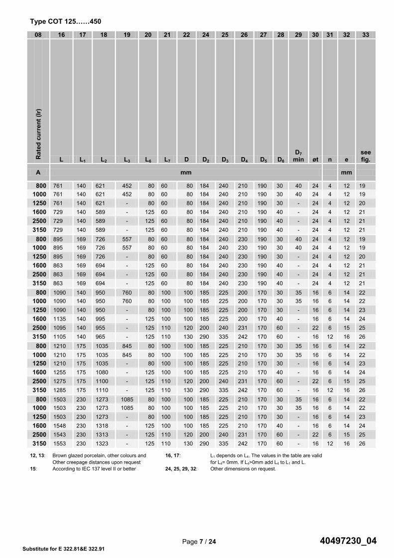
Type COT 125……450
08 16 17 18 19 20 21 22 24 25 26 27 28 29 30 31 32 33 R
ated
cur
rent
(Ir)
L L1 L2 L3 L6 L7 D D2 D3 D4 D5 D6 D7
min øt n e see fig.
A mm mm
800 761 140 621 452 80 60 80 184 240 210 190 30 40 24 4 12 19 1000 761 140 621 452 80 60 80 184 240 210 190 30 40 24 4 12 19 1250 761 140 621 - 80 60 80 184 240 210 190 30 - 24 4 12 20 1600 729 140 589 - 125 60 80 184 240 210 190 40 - 24 4 12 21 2500 729 140 589 - 125 60 80 184 240 210 190 40 - 24 4 12 21 3150 729 140 589 - 125 60 80 184 240 210 190 40 - 24 4 12 21
800 895 169 726 557 80 60 80 184 240 230 190 30 40 24 4 12 19 1000 895 169 726 557 80 60 80 184 240 230 190 30 40 24 4 12 19 1250 895 169 726 - 80 60 80 184 240 230 190 30 - 24 4 12 20 1600 863 169 694 - 125 60 80 184 240 230 190 40 - 24 4 12 21 2500 863 169 694 - 125 60 80 184 240 230 190 40 - 24 4 12 21 3150 863 169 694 - 125 60 80 184 240 230 190 40 - 24 4 12 21
800 1090 140 950 760 80 100 100 185 225 200 170 30 35 16 6 14 22 1000 1090 140 950 760 80 100 100 185 225 200 170 30 35 16 6 14 22 1250 1090 140 950 - 80 100 100 185 225 200 170 30 - 16 6 14 23 1600 1135 140 995 - 125 100 100 185 225 200 170 40 - 16 6 14 24 2500 1095 140 955 - 125 110 120 200 240 231 170 60 - 22 6 15 25 3150 1105 140 965 - 125 110 130 290 335 242 170 60 - 16 12 16 26
800 1210 175 1035 845 80 100 100 185 225 210 170 30 35 16 6 14 22 1000 1210 175 1035 845 80 100 100 185 225 210 170 30 35 16 6 14 22 1250 1210 175 1035 - 80 100 100 185 225 210 170 30 - 16 6 14 23 1600 1255 175 1080 - 125 100 100 185 225 210 170 40 - 16 6 14 24 2500 1275 175 1100 - 125 110 120 200 240 231 170 60 - 22 6 15 25 3150 1285 175 1110 - 125 110 130 290 335 242 170 60 - 16 12 16 26
800 1503 230 1273 1085 80 100 100 185 225 210 170 30 35 16 6 14 22 1000 1503 230 1273 1085 80 100 100 185 225 210 170 30 35 16 6 14 22 1250 1503 230 1273 - 80 100 100 185 225 210 170 30 - 16 6 14 23 1600 1548 230 1318 - 125 100 100 185 225 210 170 40 - 16 6 14 24 2500 1543 230 1313 - 125 110 120 200 240 231 170 60 - 22 6 15 25 3150 1553 230 1323 - 125 110 130 290 335 242 170 60 - 16 12 16 26
12, 13: Brown glazed porcelain, other colours and 16, 17: L1 depends on L4. The values in the table are valid Other creepage distances upon request for L4= 0mm. If L4>0mm add L4 to L1 and L. 15: According to IEC 137 level II or better 24, 25, 29, 32: Other dimensions on request.
Page 6 / 24 40497230_00 Substitute for E 322.81&E 322.91
Type COT 125……450
01 02 03 04 05 06 07 08 09 10 11 12 13 14 15
N°
Type
Hig
hest
vol
tage
(Um
)
Max
imum
pha
se to
ear
th v
olta
ge
Bus
hing
Dry
Pow
er fr
eque
ncy
volta
ge
with
stan
d (A
C)
Tran
sfor
mer
Pow
er fr
eque
ncy
volta
ge
with
stan
d (A
C)
Ligh
tnin
g Im
puls
e w
ithst
and
volta
ge
(BIL
)
Switc
hing
Impu
lse
wet
(SIL
): 25
0/25
00µs
Rat
ed c
urre
nt (I
r)
Con
nect
ion
to T
rans
form
er
Cab
le c
ross
sec
tion
Con
duct
or
CT
Spac
e L4
see
fig.
3 pa
ge 1
2
AD
Arc
ing
dist
ance
(min
.)
Stan
dard
cre
epag
e di
stan
ce
Mas
s A
ppro
x.
Can
tilev
er te
st lo
ad (m
in)
kV kV kV kV kV kV A mm² mm mm mm mm kg N
01 COT 125 24 14 55 50 125 / 800 cable 400
Stan
dard
: 0, 3
00, 5
00
235 600 22 2000 02 1000 cable 1) 400 22 2000 03 1250 rem.Co-cond.2) 35 28 2000 04 1600 fixed Co-cond. - 29 2000 05 2500 fixed Co-cond. - 32 2000 06 3150 fixed Co-cond. - 36 3150 07 COT 170 36 21 77 70 170 / 800 cable 400 340 *1116 31 2000 08 1000 cable 1) 400 *1116 31 2000 09 1250 rem.Co-cond.2) 35 *1116 38 2000 10 1600 fixed Co-cond. - *1116 44 2000 11 2500 fixed Co-cond. - *1116 49 2000 12 3150 fixed Co-cond. - *1116 53 3150 13 COT 250 52 30 105 95 250 / 800 cable 400 465 1300 26 2000 14 1000 cable 1) 400 26 2000 15 1250 rem.Co-cond.2) 35 35 2000 16 1600 fixed Co-cond. - 36 2000 17 2500 fixed Co-cond. - 54 3150 18 3150 fixed Co-cond. - 75 4000 19 COT 325 72,5 42 155 140 325 / 800 cable 400 600 1820 31 2000 20 1000 cable 1) 400 31 2000 21 1250 rem.Co-cond.2) 35 40 2000 22 1600 fixed Co-cond. - 44 2000 23 2500 fixed Co-cond. - 62 3150 24 3150 fixed Co-cond. - 88 4000 25 COT 450 100 58 205 185 450 / 800 cable 400 820 2540 40 2000 26 1000 cable 1) 400 40 2000 27 1250 rem.Co-cond.2) 35 52 2000 28 1600 fixed Co-cond. - 56 2000 29 2500 fixed Co-cond. - 80 3150 30 3150 fixed Co-cond. - 106 4000
Comments related to columns 1…33: 04: Bushings test voltage at 50Hz 60 sec.
09: 1) Class F insulation 2) Removable solid rod copper conductor Connection system see pages 17 to 23 11: Extension for current transformer (other extensions on request) 13: * 31mm/kV in standard
25
mm
/ kV
2
5mm
/kV
25m
m/k
V
Page 7 / 24 40497230_00 Substitute for E 322.81&E 322.91
Type COT 125……450
08 16 17 18 19 20 21 22 24 25 26 27 28 29 30 31 32 33 R
ated
cur
rent
(Ir)
L L1 L2 L3 L6 L7 D D2 D3 D4 D5 D6 D7
min øt n e see fig.
A mm mm
800 761 140 621 452 80 60 80 184 240 210 190 30 40 24 4 12 19 1000 761 140 621 452 80 60 80 184 240 210 190 30 40 24 4 12 19 1250 761 140 621 - 80 60 80 184 240 210 190 30 - 24 4 12 20 1600 729 140 589 - 125 60 80 184 240 210 190 40 - 24 4 12 21 2500 729 140 589 - 125 60 80 184 240 210 190 40 - 24 4 12 21 3150 729 140 589 - 125 60 80 184 240 210 190 40 - 24 4 12 21
800 895 169 726 557 80 60 80 184 240 230 190 30 40 24 4 12 19 1000 895 169 726 557 80 60 80 184 240 230 190 30 40 24 4 12 19 1250 895 169 726 - 80 60 80 184 240 230 190 30 - 24 4 12 20 1600 863 169 694 - 125 60 80 184 240 230 190 40 - 24 4 12 21 2500 863 169 694 - 125 60 80 184 240 230 190 40 - 24 4 12 21 3150 863 169 694 - 125 60 80 184 240 230 190 40 - 24 4 12 21
800 1090 140 950 760 80 100 100 185 225 200 170 30 35 16 6 14 22 1000 1090 140 950 760 80 100 100 185 225 200 170 30 35 16 6 14 22 1250 1090 140 950 - 80 100 100 185 225 200 170 30 - 16 6 14 23 1600 1135 140 995 - 125 100 100 185 225 200 170 40 - 16 6 14 24 2500 1095 140 955 - 125 110 120 200 240 231 170 60 - 22 6 15 25 3150 1105 140 965 - 125 110 130 290 335 242 170 60 - 16 12 16 26
800 1210 175 1035 845 80 100 100 185 225 210 170 30 35 16 6 14 22 1000 1210 175 1035 845 80 100 100 185 225 210 170 30 35 16 6 14 22 1250 1210 175 1035 - 80 100 100 185 225 210 170 30 - 16 6 14 23 1600 1255 175 1080 - 125 100 100 185 225 210 170 40 - 16 6 14 24 2500 1275 175 1100 - 125 110 120 200 240 231 170 60 - 22 6 15 25 3150 1285 175 1110 - 125 110 130 290 335 242 170 60 - 16 12 16 26
800 1503 230 1273 1085 80 100 100 185 225 210 170 30 35 16 6 14 22 1000 1503 230 1273 1085 80 100 100 185 225 210 170 30 35 16 6 14 22 1250 1503 230 1273 - 80 100 100 185 225 210 170 30 - 16 6 14 23 1600 1548 230 1318 - 125 100 100 185 225 210 170 40 - 16 6 14 24 2500 1543 230 1313 - 125 110 120 200 240 231 170 60 - 22 6 15 25 3150 1553 230 1323 - 125 110 130 290 335 242 170 60 - 16 12 16 26
12, 13: Brown glazed porcelain, other colours and 16, 17: L1 depends on L4. The values in the table are valid Other creepage distances upon request for L4= 0mm. If L4>0mm add L4 to L1 and L. 15: According to IEC 137 level II or better 24, 25, 29, 32: Other dimensions on request.
40497230_04

Page 8 / 24 40497230_00 Substitute for E 322.81&E 322.91
Type COT 550……1050
01 02 03 04 05 06 07 08 09 10 11 12 13 14 15 N
°
Type
Hig
hest
vol
tage
(Um
)
Max
imum
pha
se to
ear
th v
olta
ge
Bus
hing
Dry
Pow
er fr
eque
ncy
volta
ge
with
stan
d (A
C)
Tran
sfor
mer
Pow
er fr
eque
ncy
volta
ge
with
stan
d (A
C)
Ligh
tnin
g Im
puls
e w
ithst
and
volta
ge
(BIL
)
Switc
hing
Impu
lse
wet
(SIL
): 25
0/25
00µs
Rat
ed c
urre
nt (I
r)
Con
nect
ion
to T
rans
form
er
Cab
le c
ross
sec
tion
Con
duct
or
CT
Spac
e L4
see
fig.
3 pa
ge 1
2
AD
Arc
ing
dist
ance
(min
.)
Stan
dard
cre
epag
e di
stan
ce
Mas
s A
ppro
x.
Can
tilev
er te
st lo
ad (m
in.)
kV kV kV kV kV kV A mm² mm mm mm mm kg N
01 COT 550 123 71 255 230 550 / 800 cable 400
Stan
dard
: 0, 3
00, 5
00
1050 3100 62 3150 02 1000 cable 1) 400 62 3150 03 1250 rem.Co-cond.2) 35 74 3150 04 1600 fixed Co-cond. - 79 3150 05 2500 fixed Co-cond. - 165 4000 06 3150 fixed Co-cond. - 173 4000 07 COT 650 145 84 305 275 650 / 800 cable 400 1250 3625 81 3150 08 1000 cable 1) 400 81 3150 09 1250 rem.Co-cond.2) 35 98 3150 10 1600 fixed Co-cond. - 101 3150 11 2500 fixed Co-cond. - 190 4000 12 3150 fixed Co-cond. - 198 4000 13 COT 750 170 98 355 325 750 / 800 cable 400 1460 4250 92 4000 14 1000 cable 1) 500 92 4000 15 1250 rem.Co-cond.2) 35 111 4000 16 1600 fixed Co-cond. - 117 4000 17 2500 fixed Co-cond. - *5270 315 5000 18 3150 fixed Co-cond. - 223 5000 19 COT 1050 245 142 505 460 1050 750 800 cable 400 2150 6125 236 4000 20 750 1000 cable 1) 500 236 4000 21 750 1250 rem.Co-cond.2) 38 266 4000 22 750 1600 fixed Co-cond. - 285 4000 23 750 2500 fixed Co-cond. - 328 5000 24 750 3150 fixed Co-cond. - 332 5000 25 COT 1050 300 173 560 510 1050 850 1000 Cable 630 2400 7500 350 5000 26 850 1600 fixed Co-cond. - 440 5000 27 850 2500 fixed Co-cond. - 445 5000
Comments related to columns 1…33: 04: Bushings test voltage at 50Hz 60 sec. 09: 1) Class F insulation 2) Removable solid rod copper conductor
11: Extension for current transformer (other extensions on request) Connection system see pages 17 to 23
13: * 31mm/kV in standard
25m
m /
kV
40497230_04

Page 9 / 24 40497230_00 Substitute for E 322.81&E 322.91
Type COT 550……1050
08 16 17 18 19 20 21 22 23 24 25 26 27 28 29 30 31 32 33 R
ated
cur
rent
(Ir)
L L1 L2 L3 L6 L7 D D1 D2 D3 D4 D5 D6 D7
min øt n e see fig.
A mm mm
800 1805 310 1495 1306 80 110 120 - 250 290 231 170 30 35 16 8 15 27 1000 1805 310 1495 1306 80 110 120 - 250 290 231 170 30 35 16 8 15 27 1250 1805 310 1495 - 80 110 120 - 250 290 231 170 30 - 16 8 15 28 1600 1850 310 1540 - 125 110 120 - 250 290 231 170 40 - 16 8 15 29 2500 2089 310 1779 - 125 195 175 - 290 290 295 300 60 - 20 12 20 30 3150 2052 310 1742 - 125 195 175 - 400 450 295 300 60 - 22 12 22 31
800 2055 360 1695 1506 80 110 130 - 290 335 242 170 30 35 16 12 16 27 1000 2055 360 1695 1506 80 110 130 - 290 335 242 170 30 35 16 12 16 27 1250 2055 360 1695 - 80 110 130 - 290 335 242 170 30 - 16 12 16 28 1600 2100 360 1740 - 125 110 130 - 290 335 242 170 40 - 16 12 16 29 2500 2339 360 1979 - 125 195 175 - 290 335 295 300 60 - 20 12 20 30 3150 2302 360 1942 - 125 195 175 - 400 450 295 300 60 - 22 12 22 31
800 2325 420 1905 1716 80 110 130 - 290 335 242 170 30 35 16 12 16 27 1000 2325 420 1905 1716 80 110 130 - 290 335 242 170 30 35 16 12 16 27 1250 2325 420 1905 - 80 110 130 - 290 335 242 170 30 - 16 12 16 28 1600 2370 420 1950 - 125 110 130 - 290 335 242 170 40 - 16 12 16 29 2500 2609 420 2189 - 125 195 175 - 290 335 335 300 60 - 20 12 20 30 3150 2572 420 2152 - 125 195 175 - 400 450 295 300 60 - 22 12 22 31
800 3518 684 2834 2500 80 195 175 - 400 450 295 300 30 40 22 12 22 32 1000 3518 684 2834 2500 80 195 175 - 400 450 295 300 30 40 22 12 22 32 1250 3518 684 2834 - 80 195 175 - 400 450 295 300 30 - 22 12 22 33 1600 3563 684 2879 - 125 195 175 - 400 450 295 300 40 - 22 12 22 34 2500 3563 684 2879 - 125 195 200 - 400 450 340 300 60 - 22 12 22 35 3150 3407 684 2842 - 125 195 200 - 400 450 340 300 60 - 22 12 22 36
1000 3813 684 3129 2750 80 195 200 - 400 450 350 300 40 55 22 12 22 37 1600 3813 684 3129 - 125 195 200 - 400 450 350 300 40 - 22 12 22 38 2500 3742 650 3092 - 125 195 200 - 400 450 350 300 50 - 22 12 22 39
12, 13: Brown glazed porcelain, other colours and 16, 17: L1 depends on L4. The values in the table are valid Other creepage distances upon request for L4= 0mm. If L4>0mm add L4 to L1 and L. 15: According to IEC 137 level II or better 24, 25, 29, 32: Other dimensions on request.
Page 8 / 24 40497230_00 Substitute for E 322.81&E 322.91
Type COT 550……1050
01 02 03 04 05 06 07 08 09 10 11 12 13 14 15
N°
Type
Hig
hest
vol
tage
(Um
)
Max
imum
pha
se to
ear
th v
olta
ge
Bus
hing
Dry
Pow
er fr
eque
ncy
volta
ge
with
stan
d (A
C)
Tran
sfor
mer
Pow
er fr
eque
ncy
volta
ge
with
stan
d (A
C)
Ligh
tnin
g Im
puls
e w
ithst
and
volta
ge
(BIL
)
Switc
hing
Impu
lse
wet
(SIL
): 25
0/25
00µs
Rat
ed c
urre
nt (I
r)
Con
nect
ion
to T
rans
form
er
Cab
le c
ross
sec
tion
Con
duct
or
CT
Spac
e L4
see
fig.
3 pa
ge 1
2
AD
Arc
ing
dist
ance
(min
.)
Stan
dard
cre
epag
e di
stan
ce
Mas
s A
ppro
x.
Can
tilev
er te
st lo
ad (m
in.)
kV kV kV kV kV kV A mm² mm mm mm mm kg N
01 COT 550 123 71 255 230 550 / 800 cable 400
Stan
dard
: 0, 3
00, 5
00
1050 3100 62 3150 02 1000 cable 1) 400 62 3150 03 1250 rem.Co-cond.2) 35 74 3150 04 1600 fixed Co-cond. - 79 3150 05 2500 fixed Co-cond. - 165 4000 06 3150 fixed Co-cond. - 173 4000 07 COT 650 145 84 305 275 650 / 800 cable 400 1250 3625 81 3150 08 1000 cable 1) 400 81 3150 09 1250 rem.Co-cond.2) 35 98 3150 10 1600 fixed Co-cond. - 101 3150 11 2500 fixed Co-cond. - 190 4000 12 3150 fixed Co-cond. - 198 4000 13 COT 750 170 98 355 325 750 / 800 cable 400 1460 4250 92 4000 14 1000 cable 1) 500 92 4000 15 1250 rem.Co-cond.2) 35 111 4000 16 1600 fixed Co-cond. - 117 4000 17 2500 fixed Co-cond. - *5270 315 5000 18 3150 fixed Co-cond. - 223 5000 19 COT 1050 245 142 505 460 1050 750 800 cable 400 2150 6125 236 4000 20 750 1000 cable 1) 500 236 4000 21 750 1250 rem.Co-cond.2) 38 266 4000 22 750 1600 fixed Co-cond. - 285 4000 23 750 2500 fixed Co-cond. - 328 5000 24 750 3150 fixed Co-cond. - 332 5000 25 COT 1050 300 173 560 510 1050 850 1000 Cable 630 2400 7500 350 5000 26 850 1600 fixed Co-cond. - 440 5000 27 850 2500 fixed Co-cond. - 445 5000
Comments related to columns 1…33: 04: Bushings test voltage at 50Hz 60 sec. 09: 1) Class F insulation 2) Removable solid rod copper conductor
11: Extension for current transformer (other extensions on request) Connection system see pages 17 to 23
13: * 31mm/kV in standard
25m
m /
kV
Page 9 / 24 40497230_00 Substitute for E 322.81&E 322.91
Type COT 550……1050
08 16 17 18 19 20 21 22 23 24 25 26 27 28 29 30 31 32 33 R
ated
cur
rent
(Ir)
L L1 L2 L3 L6 L7 D D1 D2 D3 D4 D5 D6 D7
min øt n e see fig.
A mm mm
800 1805 310 1495 1306 80 110 120 - 250 290 231 170 30 35 16 8 15 27 1000 1805 310 1495 1306 80 110 120 - 250 290 231 170 30 35 16 8 15 27 1250 1805 310 1495 - 80 110 120 - 250 290 231 170 30 - 16 8 15 28 1600 1850 310 1540 - 125 110 120 - 250 290 231 170 40 - 16 8 15 29 2500 2089 310 1779 - 125 195 175 - 290 290 295 300 60 - 20 12 20 30 3150 2052 310 1742 - 125 195 175 - 400 450 295 300 60 - 22 12 22 31
800 2055 360 1695 1506 80 110 130 - 290 335 242 170 30 35 16 12 16 27 1000 2055 360 1695 1506 80 110 130 - 290 335 242 170 30 35 16 12 16 27 1250 2055 360 1695 - 80 110 130 - 290 335 242 170 30 - 16 12 16 28 1600 2100 360 1740 - 125 110 130 - 290 335 242 170 40 - 16 12 16 29 2500 2339 360 1979 - 125 195 175 - 290 335 295 300 60 - 20 12 20 30 3150 2302 360 1942 - 125 195 175 - 400 450 295 300 60 - 22 12 22 31
800 2325 420 1905 1716 80 110 130 - 290 335 242 170 30 35 16 12 16 27 1000 2325 420 1905 1716 80 110 130 - 290 335 242 170 30 35 16 12 16 27 1250 2325 420 1905 - 80 110 130 - 290 335 242 170 30 - 16 12 16 28 1600 2370 420 1950 - 125 110 130 - 290 335 242 170 40 - 16 12 16 29 2500 2609 420 2189 - 125 195 175 - 290 335 335 300 60 - 20 12 20 30 3150 2572 420 2152 - 125 195 175 - 400 450 295 300 60 - 22 12 22 31
800 3518 684 2834 2500 80 195 175 - 400 450 295 300 30 40 22 12 22 32 1000 3518 684 2834 2500 80 195 175 - 400 450 295 300 30 40 22 12 22 32 1250 3518 684 2834 - 80 195 175 - 400 450 295 300 30 - 22 12 22 33 1600 3563 684 2879 - 125 195 175 - 400 450 295 300 40 - 22 12 22 34 2500 3563 684 2879 - 125 195 200 - 400 450 340 300 60 - 22 12 22 35 3150 3407 684 2842 - 125 195 200 - 400 450 340 300 60 - 22 12 22 36
1000 3813 684 3129 2750 80 195 200 - 400 450 350 300 40 55 22 12 22 37 1600 3813 684 3129 - 125 195 200 - 400 450 350 300 40 - 22 12 22 38 2500 3742 650 3092 - 125 195 200 - 400 450 350 300 50 - 22 12 22 39
12, 13: Brown glazed porcelain, other colours and 16, 17: L1 depends on L4. The values in the table are valid Other creepage distances upon request for L4= 0mm. If L4>0mm add L4 to L1 and L. 15: According to IEC 137 level II or better 24, 25, 29, 32: Other dimensions on request.
40497230_04

Page 10 / 24 40497230_00 Substitute for E 322.81&E 322.91
Type COT 1175……1800
01 02 03 04 05 06 07 08 09 10 11 12 13 14 15 N
°
Type
Hig
hest
vol
tage
(Um
)
Max
imum
pha
se to
ear
th v
olta
ge
Bus
hing
Dry
Pow
er fr
eque
ncy
volta
ge
with
stan
d (A
C)
Tran
sfor
mer
Pow
er fr
eque
ncy
volta
ge
with
stan
d (A
C)
Ligh
tnin
g Im
puls
e w
ithst
and
volta
ge
(BIL
)
Switc
hing
Impu
lse
wet
(SIL
): 25
0/25
00µs
Rat
ed c
urre
nt (I
r)
Con
nect
ion
to T
rans
form
er
Cab
le c
ross
sec
tion
Con
duct
or
CT
Spac
e L4
see
fig.
3 pa
ge 1
2
AD
Arc
ing
dist
ance
(min
.)
Stan
dard
cre
epag
e di
stan
ce
Mas
s A
ppro
x.
Can
tilev
er te
st lo
ad (m
in)
kV kV kV kV kV kV A mm² mm mm mm mm kg N
01 COT 1175 362 209 560 510 1175 950 1000 cable 630
Stan
dard
: 0, 3
00, 5
00
2800 9115 480 5000
02 1600 Fixed cond. - 2800 5000
03 2500 Fixed cond. - 2800 540 5000
04 COT 1300 362 209 625 570 1300 950 1000 cable 630 2800 9115 500 5000
05 1600 Fixed cond. - 2800 530 5000
06 2500 Fixed cond. - 2800 560 5000
07 COT 1425 420 243 695 630 1425 1050 1000 cable 630 3300 *13750 865 5000
08 1600 Fixed cond. - 3300 *13750 930 5000
09 2500 Fixed cond. - 3300 *13750 990 5000
10 COT 1550 550 318 750 680 1550 1175 1000 cable 630 3800 14350 940 5000
11 1600 Fixed cond. - 3800 1000 5000
12 2500 Fixed cond. - 3800 1030 5000
13 COT 1675 550 318 750 680 1675 1175 1000 cable 630 3800 14350 980 5000
14 1600 Fixed cond. - 3800 1060 5000
15 2500 Fixed cond. - 3800 1100 5000
16 COT 1800 550 318 870 790 1800 1000 cable 630 4200 14350 1050 5000
17 1600 Fixed cond. - 4200 1150 5000
18 2500 Fixed cond. - 4200 1200 5000
Comments related to columns 1…33: 04: Bushings test voltage at 50Hz 60 sec. 11: Extension for current transformer (other extensions on request)
Connection system see pages 17 to 23 13: * 31mm/kV in standard for Type COT 1425
25
mm
/ k
V
25m
m/k
V
1300
40497230_04

Page 11 / 24 40497230_00 Substitute for E 322.81&E 322.91
Type COT 1175……1800
08 16 17 18 19 20 21 22 23 24 25 26 27 28 29 30 31 32 33 R
ated
cur
rent
(Ir)
L L1 L2 L3 L6 L7 D D1 D2 D3 D4 D5 D6 D7 øt n e see fig.
A mm mm
1000 4270 720 3550 3240 125 250 235 - 400 450 390 330 40 55 22 12 22 40
1600 4230 720 3510 - 125 250 235 - 400 450 390 330 40 - 22 12 22 41
2500 4230 720 3510 - 125 250 235 - 400 450 390 330 40 - 22 12 22 41
1000 4270 720 3550 3240 125 250 235 - 400 450 390 330 40 55 22 12 22 40
1600 4230 720 3510 - 125 250 235 - 400 450 390 330 40 - 22 12 22 41
2500 4230 720 3510 - 125 250 235 - 400 450 390 330 40 - 22 12 22 41
1000 5055 820 4235 3995 125 280 291 380 530 590 477 400 40 68 23 12 25 42
1600 4965 820 4145 - 125 280 291 380 530 590 477 400 40 - 23 12 25 43
2500 4965 820 4145 - 125 280 291 380 530 590 477 400 50 - 23 12 25 43
1000 5790 1055 4735 4495 125 280 291 380 530 590 455 500 40 68 23 12 25 42
1600 5700 1055 4645 - 125 280 291 380 530 590 455 500 40 - 23 12 25 43
2500 5700 1055 4645 - 125 280 291 380 530 590 455 500 50 - 23 12 25 43
1000 5935 1200 4735 4495 125 280 291 380 530 590 455 500 40 68 23 12 25 42
1600 5845 1200 4645 - 125 280 291 380 530 590 455 500 40 - 23 12 25 43
2500 5845 1200 4645 - 125 280 291 380 530 590 455 500 50 - 23 12 25 43
1000 6345 1200 5145 4895 125 280 291 380 530 590 455 500 40 68 23 12 25 42
1600 6245 1200 5045 - 125 280 291 380 530 590 455 500 40 - 23 12 25 43
2500 6255 1200 5055 - 125 280 291 380 530 590 455 500 50 - 23 12 25 43
12, 13: Brown glazed porcelain, other colours and 16, 17: L1 depends on L4. The values in the table are valid Other creepage distances upon request for L4= 0mm. If L4>0mm add L4 to L1 and L. 15: According to IEC 137 level II or better 24, 25, 29, 32: Other dimensions on request.
Page 10 / 24 40497230_00 Substitute for E 322.81&E 322.91
Type COT 1175……1800
01 02 03 04 05 06 07 08 09 10 11 12 13 14 15
N°
Type
Hig
hest
vol
tage
(Um
)
Max
imum
pha
se to
ear
th v
olta
ge
Bus
hing
Dry
Pow
er fr
eque
ncy
volta
ge
with
stan
d (A
C)
Tran
sfor
mer
Pow
er fr
eque
ncy
volta
ge
with
stan
d (A
C)
Ligh
tnin
g Im
puls
e w
ithst
and
volta
ge
(BIL
)
Switc
hing
Impu
lse
wet
(SIL
): 25
0/25
00µs
Rat
ed c
urre
nt (I
r)
Con
nect
ion
to T
rans
form
er
Cab
le c
ross
sec
tion
Con
duct
or
CT
Spac
e L4
see
fig.
3 pa
ge 1
2
AD
Arc
ing
dist
ance
(min
.)
Stan
dard
cre
epag
e di
stan
ce
Mas
s A
ppro
x.
Can
tilev
er te
st lo
ad (m
in)
kV kV kV kV kV kV A mm² mm mm mm mm kg N
01 COT 1175 362 209 560 510 1175 950 1000 cable 630
Stan
dard
: 0, 3
00, 5
00
2800 9115 480 5000
02 1600 Fixed cond. - 2800 5000
03 2500 Fixed cond. - 2800 540 5000
04 COT 1300 362 209 625 570 1300 950 1000 cable 630 2800 9115 500 5000
05 1600 Fixed cond. - 2800 530 5000
06 2500 Fixed cond. - 2800 560 5000
07 COT 1425 420 243 695 630 1425 1050 1000 cable 630 3300 *13750 865 5000
08 1600 Fixed cond. - 3300 *13750 930 5000
09 2500 Fixed cond. - 3300 *13750 990 5000
10 COT 1550 550 318 750 680 1550 1175 1000 cable 630 3800 14350 940 5000
11 1600 Fixed cond. - 3800 1000 5000
12 2500 Fixed cond. - 3800 1030 5000
13 COT 1675 550 318 750 680 1675 1175 1000 cable 630 3800 14350 980 5000
14 1600 Fixed cond. - 3800 1060 5000
15 2500 Fixed cond. - 3800 1100 5000
16 COT 1800 550 318 870 790 1800 1000 cable 630 4200 14350 1050 5000
17 1600 Fixed cond. - 4200 1150 5000
18 2500 Fixed cond. - 4200 1200 5000
Comments related to columns 1…33: 04: Bushings test voltage at 50Hz 60 sec. 11: Extension for current transformer (other extensions on request)
Connection system see pages 17 to 23 13: * 31mm/kV in standard for Type COT 1425
25
mm
/ k
V
25m
m/k
V
Page 11 / 24 40497230_00 Substitute for E 322.81&E 322.91
Type COT 1175……1800
08 16 17 18 19 20 21 22 23 24 25 26 27 28 29 30 31 32 33 R
ated
cur
rent
(Ir)
L L1 L2 L3 L6 L7 D D1 D2 D3 D4 D5 D6 D7 øt n e see fig.
A mm mm
1000 4270 720 3550 3240 125 250 235 - 400 450 390 330 40 55 22 12 22 40
1600 4230 720 3510 - 125 250 235 - 400 450 390 330 40 - 22 12 22 41
2500 4230 720 3510 - 125 250 235 - 400 450 390 330 40 - 22 12 22 41
1000 4270 720 3550 3240 125 250 235 - 400 450 390 330 40 55 22 12 22 40
1600 4230 720 3510 - 125 250 235 - 400 450 390 330 40 - 22 12 22 41
2500 4230 720 3510 - 125 250 235 - 400 450 390 330 40 - 22 12 22 41
1000 5055 820 4235 3995 125 280 291 380 530 590 477 400 40 68 23 12 25 42
1600 4965 820 4145 - 125 280 291 380 530 590 477 400 40 - 23 12 25 43
2500 4965 820 4145 - 125 280 291 380 530 590 477 400 50 - 23 12 25 43
1000 5790 1055 4735 4495 125 280 291 380 530 590 455 500 40 68 23 12 25 42
1600 5700 1055 4645 - 125 280 291 380 530 590 455 500 40 - 23 12 25 43
2500 5700 1055 4645 - 125 280 291 380 530 590 455 500 50 - 23 12 25 43
1000 5935 1200 4735 4495 125 280 291 380 530 590 455 500 40 68 23 12 25 42
1600 5845 1200 4645 - 125 280 291 380 530 590 455 500 40 - 23 12 25 43
2500 5845 1200 4645 - 125 280 291 380 530 590 455 500 50 - 23 12 25 43
1000 6345 1200 5145 4895 125 280 291 380 530 590 455 500 40 68 23 12 25 42
1600 6245 1200 5045 - 125 280 291 380 530 590 455 500 40 - 23 12 25 43
2500 6255 1200 5055 - 125 280 291 380 530 590 455 500 50 - 23 12 25 43
12, 13: Brown glazed porcelain, other colours and 16, 17: L1 depends on L4. The values in the table are valid Other creepage distances upon request for L4= 0mm. If L4>0mm add L4 to L1 and L. 15: According to IEC 137 level II or better 24, 25, 29, 32: Other dimensions on request.
40497230_04

Page 12 / 24 40497230_00 Substitute for E 322.81&E 322.91
Dimensional Drawing
L1
D7
Fig. 1
COT 550…1050 (Um =245kV), 3150 A
COT 1050 (Um=300kV), 2500A
COT 1175 … 1800
Fig. 3 Fig. 5
Fig. 2
Fig. 4
D1 Only for COT ≥ 420 kV
D5
D4
D6 View A
L2
L6
L3
AD
L
L1
L7 e
≥ 30
L4
D
Page 12 / 24 40497230_00 Substitute for E 322.81&E 322.91
Dimensional Drawing
L1
D7
Fig. 1
COT 550…1050 (Um =245kV), 3150 A
COT 1050 (Um=300kV), 2500A
COT 1175 … 1800
Fig. 3 Fig. 5
Fig. 2
Fig. 4
D1 Only for COT ≥ 420 kV
D5
D4
D6 View A
L2
L6
L3
AD
L
L1
L7 e
≥ 30
L4
D
40497230_04

Page 13 / 24 40497230_00 Substitute for E 322.81&E 322.91
Porcelain and composite insulator
All COT(C) can be equipped with silicone rubber insulators upon request without affecting dimensions except D4
Porcelain Insulator (Type COT) Composite Insulator (Type COTC)
Brown color (RAL 8016)
Gray color (ANSI gray N70)
Alternate sheds (ANSI gray N70)
Helicoil sheds (ANSI gray N70)
D4 D4 D4 D4
Page 12 / 24 40497230_00 Substitute for E 322.81&E 322.91
Dimensional Drawing
L1
D7
Fig. 1
COT 550…1050 (Um =245kV), 3150 A
COT 1050 (Um=300kV), 2500A
COT 1175 … 1800
Fig. 3 Fig. 5
Fig. 2
Fig. 4
D1 Only for COT ≥ 420 kV
D5
D4
D6 View A
L2
L6
L3
AD
L
L1
L7 e
≥ 30
L4
D
Page 13 / 24 40497230_00 Substitute for E 322.81&E 322.91
Porcelain and composite insulator
All COT(C) can be equipped with silicone rubber insulators upon request without affecting dimensions except D4
Porcelain Insulator (Type COT) Composite Insulator (Type COTC)
Brown color (RAL 8016)
Gray color (ANSI gray N70)
Alternate sheds (ANSI gray N70)
Helicoil sheds (ANSI gray N70)
D4 D4 D4 D4
40497230_04

Page 14 / 24 40497230_00 Substitute for E 322.81&E 322.91
Standard
Oil level indicator COT 125, COT 170
Oil level indicator COT 250 … COT 1050
Ø20
Ø60
Test tap (2kV)
Multiple spring contact
O-ring gasket
22
Air escape screw
Flat gasket
6
Fig. 6 Fig. 7
Fig. 8 Fig. 9
Page 14 / 24 40497230_00 Substitute for E 322.81&E 322.91
Standard
Oil level indicator COT 125, COT 170
Oil level indicator COT 250 … COT 1050
Ø20
Ø60
Test tap (2kV)
Multiple spring contact
O-ring gasket
22
Air escape screw
Flat gasket
6
Fig. 6 Fig. 7
Fig. 8 Fig. 9
40497230_04

Page 15 / 24 40497230_00 Substitute for E 322.81&E 322.91
Options
Type S min max
mm
COT 125 - -
COT 170 - -
COT 250 220 270
COT 325 300 390
COT 450 430 520
COT 550 420 650
COT 650 500 750
COT 750 500 850
COT 1050 750 1200
S
Magnetic oil level indicator (Ø95) COT 250 … COT 1800
Arcing horns
Oil sampling device Voltage tap according to ANSI/IEEE (20kV)
Valve Multiple spring contact
Fig. 10 Fig. 11
Fig. 12 Fig. 13
Page 14 / 24 40497230_00 Substitute for E 322.81&E 322.91
Standard
Oil level indicator COT 125, COT 170
Oil level indicator COT 250 … COT 1050
Ø20
Ø60
Test tap (2kV)
Multiple spring contact
O-ring gasket
22
Air escape screw
Flat gasket
6
Fig. 6 Fig. 7
Fig. 8 Fig. 9
Page 15 / 24 40497230_00 Substitute for E 322.81&E 322.91
Options
Type S min max
mm
COT 125 - -
COT 170 - -
COT 250 220 270
COT 325 300 390
COT 450 430 520
COT 550 420 650
COT 650 500 750
COT 750 500 850
COT 1050 750 1200
S
Magnetic oil level indicator (Ø95) COT 250 … COT 1800
Arcing horns
Oil sampling device Voltage tap according to ANSI/IEEE (20kV)
Valve Multiple spring contact
Fig. 10 Fig. 11
Fig. 12 Fig. 13
40497230_04

Page 16 / 24 40497230_00 Substitute for E 322.81&E 322.91
Recommendations for lead out arrangement
Cable insulation and distance to grounded parts
Type Min.
insulation thickness
Min. distance to grounded parts
S R R1
mm
COT 125 5 65 -
COT 170 5 75 -
COT 250 10 85 -
COT 325 10 120 -
COT 450 12 135 -
COT 550 12 145 250
COT 650 15 180 275
COT 750 15 225 300
COT 1050 20 300 375 COT 1175
to COT 1800
- - See spec 40497124
These bushings are equipped on the lower end with a cone shaped epoxy resin tube and an embedded electrode. Therefore, additional barriers or electrodes may be omitted and distance to ground is reduced
Oil conditions: Mineral oil with less than 10ppm water content and dielectric strength higher than 60kV (acc. to IEC 60156)
Embedded shield External shield
Draw lead insulation COT 550…750 COT 1050
Ø35,7 Ø40
Ø80 (Um=245kV) Ø94 (Um=300kV)
S
15°
S
R
R1
S
28 50
30°
Fig. 14 Fig. 15
Fig. 16 Fig. 17
40497230_04

Page 17 / 24 40497230_00 Substitute for E 322.81&E 322.91
Removable split conductor
Oil side end
COT 125 … COT 1175 1250 A
COT 125, COT 170
30
Ø29
3 fixing screws
Removable split conductor
Cable bolt
30
Ø80
Ø40
Ø80
Ø40
Conductor Ø35
Ø29
30
8
Ø40
Ø80
125
Position of standard split conductor.
Others positions on request
Fig. 18
… 1000A
… 1250A
1600 … 3150A
Fixed copper-conductor
Removable copper conductor
Cable
Fig. 21 Fig. 19 Fig. 20
Page 16 / 24 40497230_00 Substitute for E 322.81&E 322.91
Recommendations for lead out arrangement
Cable insulation and distance to grounded parts
Type Min.
insulation thickness
Min. distance to grounded parts
S R R1
mm
COT 125 5 65 -
COT 170 5 75 -
COT 250 10 85 -
COT 325 10 120 -
COT 450 12 135 -
COT 550 12 145 250
COT 650 15 180 275
COT 750 15 225 300
COT 1050 20 300 375 COT 1175
to COT 1800
- - See spec 40497124
These bushings are equipped on the lower end with a cone shaped epoxy resin tube and an embedded electrode. Therefore, additional barriers or electrodes may be omitted and distance to ground is reduced
Oil conditions: Mineral oil with less than 10ppm water content and dielectric strength higher than 60kV (acc. to IEC 60156)
Embedded shield External shield
Draw lead insulation COT 550…750 COT 1050
Ø35,7 Ø40
Ø80 (Um=245kV) Ø94 (Um=300kV)
S
15°
S
R
R1
S
28 50
30°
Fig. 14 Fig. 15
Fig. 16 Fig. 17
Page 17 / 24 40497230_00 Substitute for E 322.81&E 322.91
Removable split conductor
Oil side end
COT 125 … COT 1175 1250 A
COT 125, COT 170
30
Ø29
3 fixing screws
Removable split conductor
Cable bolt
30
Ø80
Ø40
Ø80
Ø40
Conductor Ø35
Ø29
30
8
Ø40
Ø80
125
Position of standard split conductor.
Others positions on request
Fig. 18
… 1000A
… 1250A
1600 … 3150A
Fixed copper-conductor
Removable copper conductor
Cable
Fig. 21 Fig. 19 Fig. 20
40497230_04
Page 18 / 24 40497230_00 Substitute for E 322.81&E 322.91
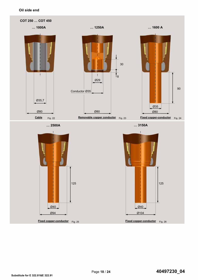
Oil side end
COT 250 … COT 450
… 1000A
… 1250A
… 1600 A
90
Fixed copper-conductor
Removable copper conductor
Cable
Ø35,7
Ø80
… 2500A
… 3150A
Fixed copper-conductor
Fixed copper-conductor
30
Ø35
Ø80
Ø40
Ø94
125
Ø40
Ø104
125
Conductor Ø35
Ø80
Ø29 8
Fig. 22 Fig. 23 Fig. 24
Fig. 25 Fig. 26
Page 18 / 24 40497230_00 Substitute for E 322.81&E 322.91
Oil side end
COT 250 … COT 450
… 1000A
… 1250A
… 1600 A
90
Fixed copper-conductor
Removable copper conductor
Cable
Ø35,7
Ø80
… 2500A
… 3150A
Fixed copper-conductor
Fixed copper-conductor
30
Ø35
Ø80
Ø40
Ø94
125
Ø40
Ø104
125
Conductor Ø35
Ø80
Ø29 8
Fig. 22 Fig. 23 Fig. 24
Fig. 25 Fig. 26
40497230_04

Page 19 / 24 40497230_00 Substitute for E 322.81&E 322.91
Oil side end
Ø160
Ø240
125 150 195
Ø40 Ø86
Ø114
125
22,5
15°
Ø40
30
41
Conductor Ø35
Ø68
Ø29
28
Ø35,7
Ø68
15°
COT 550 … COT 750
… 1000A
… 1250A
… 1600 A
Fixed copper-conductor
Removable copper conductor
Cable
… 2500A
… 3150A
Fixed copper-conductor with removable screwed shield
Fixed copper-conductor
Ø35
Ø68
90
Fig. 27 Fig. 28 Fig. 29
Fig. 30 Fig. 31
Page 18 / 24 40497230_00 Substitute for E 322.81&E 322.91
Oil side end
COT 250 … COT 450
… 1000A
… 1250A
… 1600 A
90
Fixed copper-conductor
Removable copper conductor
Cable
Ø35,7
Ø80
… 2500A
… 3150A
Fixed copper-conductor
Fixed copper-conductor
30
Ø35
Ø80
Ø40
Ø94
125
Ø40
Ø104
125
Conductor Ø35
Ø80
Ø29 8
Fig. 22 Fig. 23 Fig. 24
Fig. 25 Fig. 26
Page 19 / 24 40497230_00 Substitute for E 322.81&E 322.91
Oil side end
Ø160
Ø240
125 150 195
Ø40 Ø86
Ø114
125
22,5
15°
Ø40
30
41
Conductor Ø35
Ø68
Ø29
28
Ø35,7
Ø68
15°
COT 550 … COT 750
… 1000A
… 1250A
… 1600 A
Fixed copper-conductor
Removable copper conductor
Cable
… 2500A
… 3150A
Fixed copper-conductor with removable screwed shield
Fixed copper-conductor
Ø35
Ø68
90
Fig. 27 Fig. 28 Fig. 29
Fig. 30 Fig. 31
40497230_04

Page 20 / 24 40497230_00 Substitute for E 322.81&E 322.91
Oil side end
Ø180
Ø260
125 170
230
Ø40
Conductor Ø38
Ø119
Ø29
30
78
Ø35
90
Ø119
Ø40
Ø134
Ø95
125
COT 1050, Um = 245 kV
… 1000A
… 1250A
… 1600 A
Fixed copper-conductor
Removable copper conductor
Cable
… 2500A
… 3150A
Fixed copper-conductor with removable screwed shield
Fixed copper-conductor
Ø40
Ø119
25°
14
Ø80
50
30°
Fig. 32 Fig. 33 Fig. 34
Fig. 35 Fig. 36
40497230_04

Page 21 / 24 40497230_00 Substitute for E 322.81&E 322.91
Oil side end
Fixed copper-conductor with removable screwed shield
Ø180
Ø260
125 170
230
Ø40
Fixed copper-conductor
Ø35
Ø134
Ø95
90
COT 1050, Um = 300 kV
… 1000A
Cable
… 2500A
… 1600A
Ø55
25°
14
30°
50
Ø134
Ø95
Fig. 37 Fig. 38
Fig. 39
Page 20 / 24 40497230_00 Substitute for E 322.81&E 322.91
Oil side end
Ø180
Ø260
125 170
230
Ø40
Conductor Ø38
Ø119
Ø29
30
78
Ø35
90
Ø119
Ø40
Ø134
Ø95
125
COT 1050, Um = 245 kV
… 1000A
… 1250A
… 1600 A
Fixed copper-conductor
Removable copper conductor
Cable
… 2500A
… 3150A
Fixed copper-conductor with removable screwed shield
Fixed copper-conductor
Ø40
Ø119
25°
14
Ø80
50
30°
Fig. 32 Fig. 33 Fig. 34
Fig. 35 Fig. 36
Page 21 / 24 40497230_00 Substitute for E 322.81&E 322.91
Oil side end
Fixed copper-conductor with removable screwed shield
Ø180
Ø260
125 170
230
Ø40
Fixed copper-conductor
Ø35
Ø134
Ø95
90
COT 1050, Um = 300 kV
… 1000A
Cable
… 2500A
… 1600A
Ø55
25°
14
30°
50
Ø134
Ø95
Fig. 37 Fig. 38
Fig. 39
40497230_04

Page 22 / 24 40497230_00 Substitute for E 322.81&E 322.91
Oil side end
Ø110
Ø190
80
120
Ø55
Ø125
Oil side connector according to customer request
Ø160
Oil side connector according to customer request
Ø210
Ø330
210 280 Ø68
Ø160
Fixed conductor
COT 1175 … 1300
… 1000A
Cable with fixed shield
… 1600A
Fixed conductor
COT 1425 … 1800
… 1000A
Cable with fixed shield
… 1600A
Fig. 40 Fig. 41
Fig. 42 Fig. 43
40497230_04

Page 23 / 24 40497230_00 Substitute for E 322.81&E 322.91
Oil side end : External shields
FIXED SHIELD
SHIELD WITH BAYONET SYSTEM
SCREWED SHIELD
Ø D
3 x M6 depth 15mm equidistant on a drilling diameter D
Connection according to customer drawing
A
Detail A
Fig. 44
Fig. 45 Fig. 46
Page 22 / 24 40497230_00 Substitute for E 322.81&E 322.91
Oil side end
Ø110
Ø190
80
120
Ø55
Ø125
Oil side connector according to customer request
Ø160
Oil side connector according to customer request
Ø210
Ø330
210 280 Ø68
Ø160
Fixed conductor
COT 1175 … 1300
… 1000A
Cable with fixed shield
… 1600A
Fixed conductor
COT 1425 … 1800
… 1000A
Cable with fixed shield
… 1600A
Fig. 40 Fig. 41
Fig. 42 Fig. 43
Page 23 / 24 40497230_00 Substitute for E 322.81&E 322.91
Oil side end : External shields
FIXED SHIELD
SHIELD WITH BAYONET SYSTEM
SCREWED SHIELD
Ø D
3 x M6 depth 15mm equidistant on a drilling diameter D
Connection according to customer drawing
A
Detail A
Fig. 44
Fig. 45 Fig. 46
40497230_04

Trench® France SAS16, rue du Général CassagnouB.P.80070 F-68302 Saint-Louis Cedex France Phone : +33 3 89 70 23 23Fax : +33 3 89 70 23 59
substitute for E 322.81&E 322.91
40497230_04
Product Range
Bushings for
• Power Transformers up to 550 kV, 3150A
• High Current Application up to 52 kV, 31,5KA
• Transformer to SF6 connection up to 550kV
• Gas-insulated Switchgear (GIS) up to 800 kV, 6000A
• Generators up to 36 kV, 50000 A
• Railways
• Buildings , Wall up to 245 kV, 5000 A
• Bushings according Standard IEC 60137
• Bushings according to customer’s special specification
Quality
At Trench quality is a way of life. Trench quality assurancecomplies with the most stringent standards of ISO 9001 and ISO 14001.
Certified by AFAQ since 1994
imprimerie de saint-louis
All rights reserved.Brands and trademarks used in this documentare the property of Trench®Subject to change without prior notice.The information in this document contains general descriptions of the technical options which are not necessarily available in every single case. The required features must therefore be defined in each individual case when concluding the contract.
Trench® Limited Bushing Sales Office1865 Clements RoadPickering, ONL1W 3R8CanadaPhone : +1-647-925-9799
+1-647-925-9793Fax : +1-416-751-6952