on the development of a next-generation sensor/actuator
TRANSCRIPT

Paper ID #33181
On the Development of a Next-Generation Sensor/Actuator Module forAutomation Labs
Mr. Bradley Lane Kicklighter, University of Southern Indiana
Brad holds a BS in Electrical Engineering from Rose-Hulman Institute of Technology (1989) and an MSin Electrical and Computer Engineering from Purdue University (2001).
His past work experience includes eleven years at Delphi (formerly Delco Electronics) as an AdvancedProject Engineer, eleven years at Whirlpool Corporation as a Lead Engineer/Solution Architect, and threeyears at Ivy Tech Community College as an Instructor/Program Chair of Pre-Engineering. Since 2015,he has been employed at the University of Southern Indiana as an Assistant Professor of ManufacturingEngineering Technology.
He holds three patents, has served as an IEEE section officer since 2004, and has been a Licensed Profes-sional Engineer in the State of Indiana since 2005.
c©American Society for Engineering Education, 2021
On the Development of a Next Generation Sensor/Actuator Module for Automation Labs
Abstract
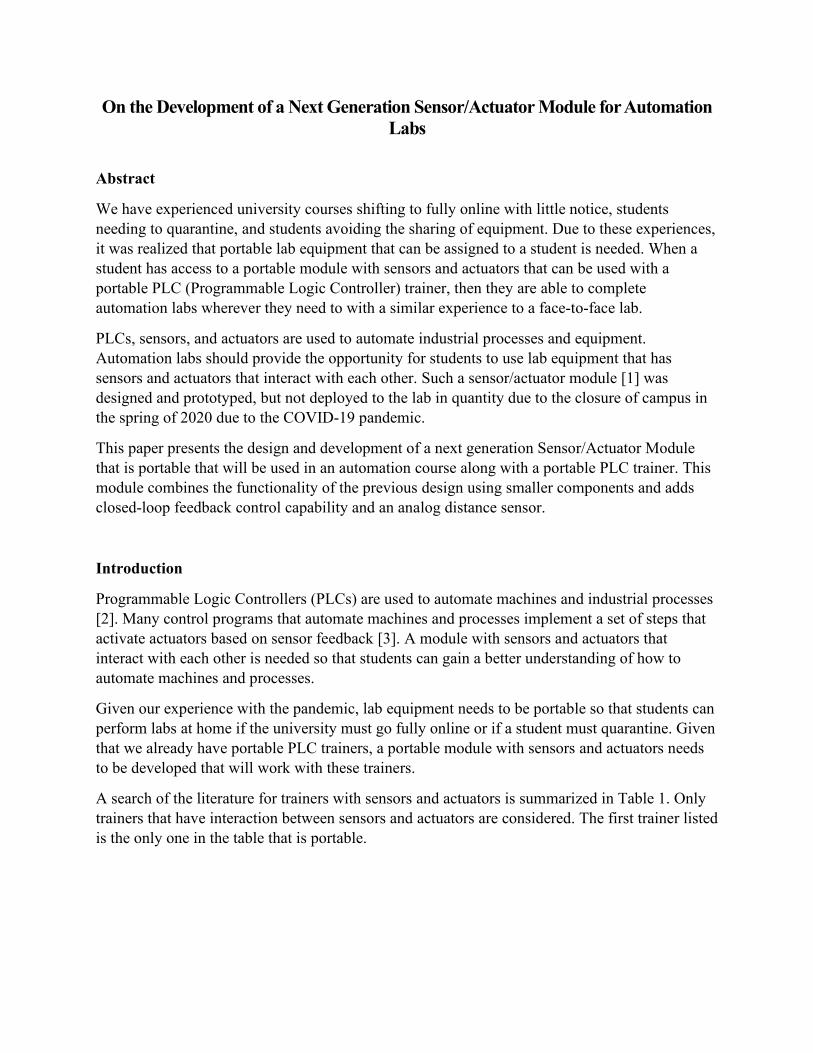
We have experienced university courses shifting to fully online with little notice, students needing to quarantine, and students avoiding the sharing of equipment. Due to these experiences, it was realized that portable lab equipment that can be assigned to a student is needed. When a student has access to a portable module with sensors and actuators that can be used with a portable PLC (Programmable Logic Controller) trainer, then they are able to complete automation labs wherever they need to with a similar experience to a face-to-face lab.
PLCs, sensors, and actuators are used to automate industrial processes and equipment. Automation labs should provide the opportunity for students to use lab equipment that has sensors and actuators that interact with each other. Such a sensor/actuator module [1] was designed and prototyped, but not deployed to the lab in quantity due to the closure of campus in the spring of 2020 due to the COVID-19 pandemic.
This paper presents the design and development of a next generation Sensor/Actuator Module that is portable that will be used in an automation course along with a portable PLC trainer. This module combines the functionality of the previous design using smaller components and adds closed-loop feedback control capability and an analog distance sensor.
Introduction
Programmable Logic Controllers (PLCs) are used to automate machines and industrial processes [2]. Many control programs that automate machines and processes implement a set of steps that activate actuators based on sensor feedback [3]. A module with sensors and actuators that interact with each other is needed so that students can gain a better understanding of how to automate machines and processes.
Given our experience with the pandemic, lab equipment needs to be portable so that students can perform labs at home if the university must go fully online or if a student must quarantine. Given that we already have portable PLC trainers, a portable module with sensors and actuators needs to be developed that will work with these trainers.
A search of the literature for trainers with sensors and actuators is summarized in Table 1. Only trainers that have interaction between sensors and actuators are considered. The first trainer listed is the only one in the table that is portable.

Table 1: Trainers with Sensors and Actuators
Control Type Sensors Actuators Interaction Motion [4] Encoder,
Inductive proximity sensor
Stepper motor A stepper motor connected to an encoder with a belt that has metal attached to it sensed by an inductive proximity sensor.
Motion [5] Photoelectric sensor, Inductive proximity sensor
AC motors, Solenoid valve, Pneumatic cylinder
AC motors drive a conveyor belt with a pallet on it that is sensed by photoelectric and inductive proximity sensors. The pallet is removed from the conveyor by a pneumatic cylinder driven by a solenoid valve.
Motion [6] Photoelectric sensor
AC motor, Solenoid valve, Pneumatic actuator, Automatic labeler
An AC motor drives a conveyor belt that moves a part until it is sensed by a photoelectric sensor. An automatic labeler is triggered when a part is sensed.
Temperature [7] Thermocouple Solid state relay, Heating element, Blower
A heating element, driven by a solid-state relay, is in an air stream provided by a blower. The temperature of the heating element is controlled based on feedback from a thermocouple.
Temperature [8] Thermocouple Solid state relay, Heating element
A heating element is driven by a solid-state relay. The temperature of the heating element is controlled based on feedback from a thermocouple.
Flow [9] Flow meter Blower, Stepper Motor
A blower provides air flow that is varied by a vane driven by a stepper motor. The air flow is controlled based on feedback from a flow meter.
Two examples of commercially available trainers that include sensors and actuators are the LearnLab PLC Training System [10] and the Amatrol Portable PLC Training System [11]. The LearnLab trainer is $2,595 USD and has an AutomationDirect Click PLC, limit switches, relays, a motor starter, and a contactor. However, the unit is not portable and does not have interaction between the sensors and actuators. The Amatrol trainer is $7,620 USD (based on 2015 pricing) has a Siemens S7-1200 PLC, color touchscreen human machine interface, temperature sensor, encoder, heater, motor, stepper motor, and motor speed control. The unit is portable and has interaction between sensors and actuators to allow temperature and motion control.
The needs have been translated into a set of requirements from which a portable module with sensors and actuators has been developed (see Figure 1).

Figure 1: Sensor/Actuator Module
The design of this version of the Sensor/Actuator Module began in June 2020 and was completed in February 2021. The evolution of the design and the choices made will be explored.
Course
ENGR 382 SCADA (Supervisory Control and Data Acquisition) Systems Design is an upper-division course taught to students in the Engineering Department as an elective or required course, depending upon the program. The following are the course learning outcomes:
1. Understand common Industrial Automation concepts, methods, and control algorithms.
2. Understand sensors and actuators used in Industrial Automation tasks. 3. Design Piping & Instrumentation Diagrams (P&IDs) for simple process systems. 4. Measure process variables in response to process parameters and analyze the resulting
process behavior. 5. Understand Programmable Logic Controller (PLC) components, signal interface
methods, and applications. 6. Design and write PLC control programs. Recognize other control program language
formats defined in the IEC 61131-3 standard. 7. Design and program suitable Human Machine Interface systems. 8. Understand common industrial networking topologies, protocols, and hardware.
Most of the laboratory activities for ENGR 382 involve programming a programmable logic controller (PLC) that is part of a PLC Trainer. See the Appendix for high-level descriptions of the laboratory activities related to the Sensor/Actuator Module.
PLC Trainer
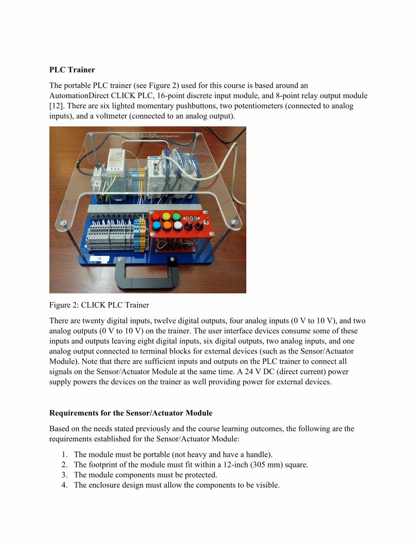
The portable PLC trainer (see Figure 2) used for this course is based around an AutomationDirect CLICK PLC, 16-point discrete input module, and 8-point relay output module [12]. There are six lighted momentary pushbuttons, two potentiometers (connected to analog inputs), and a voltmeter (connected to an analog output).
Figure 2: CLICK PLC Trainer
There are twenty digital inputs, twelve digital outputs, four analog inputs (0 V to 10 V), and two analog outputs (0 V to 10 V) on the trainer. The user interface devices consume some of these inputs and outputs leaving eight digital inputs, six digital outputs, two analog inputs, and one analog output connected to terminal blocks for external devices (such as the Sensor/Actuator Module). Note that there are sufficient inputs and outputs on the PLC trainer to connect all signals on the Sensor/Actuator Module at the same time. A 24 V DC (direct current) power supply powers the devices on the trainer as well providing power for external devices.
Requirements for the Sensor/Actuator Module
Based on the needs stated previously and the course learning outcomes, the following are the requirements established for the Sensor/Actuator Module:
1. The module must be portable (not heavy and have a handle). 2. The footprint of the module must fit within a 12-inch (305 mm) square. 3. The module components must be protected. 4. The enclosure design must allow the components to be visible.
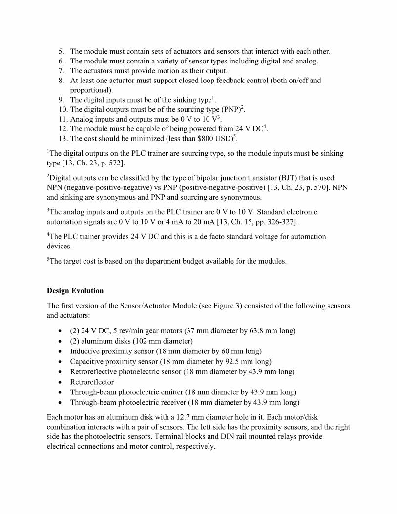
5. The module must contain sets of actuators and sensors that interact with each other. 6. The module must contain a variety of sensor types including digital and analog. 7. The actuators must provide motion as their output. 8. At least one actuator must support closed loop feedback control (both on/off and
proportional). 9. The digital inputs must be of the sinking type1. 10. The digital outputs must be of the sourcing type (PNP)2. 11. Analog inputs and outputs must be 0 V to 10 V3. 12. The module must be capable of being powered from 24 V DC4. 13. The cost should be minimized (less than $800 USD)5.
1The digital outputs on the PLC trainer are sourcing type, so the module inputs must be sinking type [13, Ch. 23, p. 572]. 2Digital outputs can be classified by the type of bipolar junction transistor (BJT) that is used: NPN (negative-positive-negative) vs PNP (positive-negative-positive) [13, Ch. 23, p. 570]. NPN and sinking are synonymous and PNP and sourcing are synonymous. 3The analog inputs and outputs on the PLC trainer are 0 V to 10 V. Standard electronic automation signals are 0 V to 10 V or 4 mA to 20 mA [13, Ch. 15, pp. 326-327]. 4The PLC trainer provides 24 V DC and this is a de facto standard voltage for automation devices. 5The target cost is based on the department budget available for the modules.
Design Evolution
The first version of the Sensor/Actuator Module (see Figure 3) consisted of the following sensors and actuators:
• (2) 24 V DC, 5 rev/min gear motors (37 mm diameter by 63.8 mm long) • (2) aluminum disks (102 mm diameter) • Inductive proximity sensor (18 mm diameter by 60 mm long) • Capacitive proximity sensor (18 mm diameter by 92.5 mm long) • Retroreflective photoelectric sensor (18 mm diameter by 43.9 mm long) • Retroreflector • Through-beam photoelectric emitter (18 mm diameter by 43.9 mm long) • Through-beam photoelectric receiver (18 mm diameter by 43.9 mm long)
Each motor has an aluminum disk with a 12.7 mm diameter hole in it. Each motor/disk combination interacts with a pair of sensors. The left side has the proximity sensors, and the right side has the photoelectric sensors. Terminal blocks and DIN rail mounted relays provide electrical connections and motor control, respectively.

Figure 3: First Generation Sensor/Actuator Module Prototype
For the next generation Sensor/Actuator Module, smaller components are selected, and the terminal blocks and DIN rail mounted relays are replaced with a printed circuit assembly. The same photoelectric sensors are used.
• (2) 6 V DC, 13 rev/min gear motors (12 mm by 10 mm by 27.5 mm long) • (2) aluminum disks (76.2 mm diameter) • Inductive proximity sensor (12 mm diameter by 45 mm long) • Capacitive proximity sensor (12 mm diameter by 61.2 mm long)
Figure 4 is a comparison of size between the current and previous gear motors.
Figure 4: Gear Motor Size Comparison (Pololu)
Initially, two other modules were conceived to be companion modules to the new Sensor/Actuator Module: a proportional control module and an ultrasonic distance sensor module. It became apparent that all three modules could be combined into a single module. This saves space and certain components can be shared such as the enclosure and printed circuit assembly.

Figure 5 is the context diagram showing the interconnections between the PLC trainer and the Sensor/Actuator Module.
CLICK PLC Trainer
LNG
24V0V
L MTR CWL MTR CCW
M MTR MODEM MTR DIM MTR ANR MTR CW
R MTR CCW
Sensor/Actuator Module
IND PROXCAP PROX
ENC AENC B
RETRO REFLTHRU BEAMUS SENSOR
120 V AC
Figure 5: Context Diagram
See the Appendix for more information about the module signals.
Figure 6 shows the block diagram of the Sensor/Actuator Module.

M
LeftMotor
M
Aluminum Disk with Hole
RightMotor
M
MiddleMotor
Inductive Proximity
Sensor
Capacitive Proximity
Sensor
Photoelectric Through-
Beam Emitter
24V
0V
R MTR CW
R MTR CCW
IND PROX
CAP PROX
RETRO REFL
THRU BEAM
M MTR MODE
M MTR DI
M MTR AN
Relay Motor Drive
Photoelectric Through-
Beam Receiver
Photoelectric Retroreflective
Sensor
Analog Ultrasonic Distance Sensor
US SENSOR
Aluminum Disk with Hole
L MTR CW
L MTR CCW
Relay Motor Drive
Motor Speed Drive
Hall Effect Quadrature
Encoder
ENC A
ENC B
To motor drives and sensors
Retroreflector
Figure 6: Sensor/Actuator Module Block Diagram

The left and right motors are 6 V DC motors, 13 rev/min, with bi-directional drive connected to aluminum disks that interact with proximity sensors (inductive and capacitive) and photoelectric sensors (retroreflective and through-beam).
The middle motor is a 6 V DC motor, 2500 rev/min, with digital and proportional (analog) control capability plus quadrature encoder feedback to allow motor speed control. An Arduino compatible microcontroller provides the motor speed drive, and the quadrature encoder signals are level shifted to 24 V DC.
Lastly, there is an analog ultrasonic distance sensor with 0 V to 10 V analog output to teach sensor calibration.
Component Selection
Table 2 summarizes the sensors and actuators selected for the Sensor/Actuator Module. Pictures are from the respective manufacturer.
Table 2: Selected Sensors and Actuators
Manufacturer Part Number Description Picture
Pololu 1596 [14] Micro metal gear motor
AutomationDirect PNM6-CP-4H [15] Inductive proximity sensor
AutomationDirect CM1-AP-2H [16] Capacitive proximity sensor
AutomationDirect FBP-DP-0E [17] Retroreflective sensor

AutomationDirect FBE-00-0E [18] Through-beam emitter
AutomationDirect FBR-LP-0E [19] Through-beam receiver
Pololu 2200 [20] Micro metal gear motor
Pololu 4761 [21] Magnetic encoder
AutomationDirect UK6A-D1-0A [22] Ultrasonic distance sensor
Printed Circuit Assembly
The printed circuit assembly (PCA) was custom designed and fabricated (see Figure 7).
Figure 7: Printed Circuit Assembly

The PCA serves the following purposes in the Sensor/Actuator Module:
• The wiring harness between the Sensor/Actuator Module and the PLC trainer connects to the PCA.
• All sensors and actuators connect to the PCA. • Contains the relays for controlling left and right motors. • Provides on/off and proportional control of the middle motor. • Provides 5 V DC power for all three motors.
Since the student connects the wiring harness to the PLC trainer, which includes 24 V DC power, there is reverse voltage protection for all devices on the PCA using a field effect transistor (FET). In addition, the microcontroller has a switching step-down regulator that produces 5 V.
A Pololu A-Star 32U4 Mini microcontroller [23] handles the on/off and proportional control of the middle motor. Incoming signals from the PLC trainer are optically isolated and level shifted to 5 V for the microcontroller. Outgoing signals are level shifted from 5 V to 24 V. The 0 V to 10 V analog signal from the PLC trainer for proportional control is divided down to 0 V to 5 V for the microcontroller’s analog-to-digital input.
All motor signals have transient voltage suppression and noise filtering.
See the Appendix for the schematic diagram of the printed circuit assembly.
Construction
Acrylic plates (3 mm thick) are cut out on a laser engraver and along with aluminum standoffs, form the enclosure and structure of the module. An acrylic handle (5 mm thick) is attached to the top plate. The PCA and ultrasonic distance sensor are attached to the bottom plate. The motors, proximity sensors, through-beam emitter, and retroreflector are attached to the lower plate. The through-beam receiver and retroreflective sensor are attached to the upper plate. 3D printed couplers attach the aluminum disks to the left and right motors. The aluminum disks are cut out on a water jet. Figure 8 shows the front side of module.

Figure 8: Module Front Side View
The PCA consists of through hole and surface mount components. The surface mount components are reflow soldered with a reflow oven and the through hole components are hand soldered.
The upper and top plates are clear to allow visibility of motors and disks. All components are visible from the sides so the status LEDs on the sensors are visible.
The module is 11.5 inches (292 mm) wide by 5 inches (127 mm) deep by 11.5 inches (292 mm) tall (including the handle) and weighs two pounds (907 g).
Figures 9 and 10 show the left and right sides of the module.

Figure 9: Module Left Side View Figure 10: Module Right Side View
Conclusions
The cost of the module is less than $600, which is less than the $800 target cost. All requirements are met by this design which combined three different modules into one. A set of laboratory activities is described in the Appendix.
Between the PLC trainer, Sensor/Actuator Module, and laboratory activities, students should gain a good understanding of various ladder logic programming and control topics such as:
• Sequential programming • Looping • Counters • Timers • Analog sensors • Encoders • Closed-loop control (on/off, proportional, PID) • PID tuning

References
[1] B. Kicklighter, “Design and Development of a Sensor/Actuator Module to Enhance Programmable Logic Controller (PLC) Laboratory Activities,” in 2020 ASEE Virtual Annual Conference Content Access Proceedings, Virtual Online, 2020, p. 34389, DOI: 10.18260/1-2--34389 [Online]. Available: http://peer.asee.org/34389. [Accessed: 01-Mar-2021].
[2] J. Rehg and G. Sartori, Programmable Logic Controllers, Second Edition. Upper Saddle River, NJ: Pearson Prentice Hall, 2009.
[3] J. Stenerson, Fundamentals of Programmable Logic Controllers, Sensors, and Communications, Third Edition. Upper Saddle River, NJ: Pearson Prentice Hall, 2004.
[4] W. Xiao et al., “A Briefcase Hardware Design for Data Acquisition Training,” in 2017 ASEE Annual Conference & Exposition Proceedings, Columbus, Ohio, 2017, p. 27437, DOI: 10.18260/1-2--27437 [Online]. Available: http://peer.asee.org/27437. [Accessed: 02-Feb-2021].
[5] M. Ghone, M. Schubert, and J. R. Wagner, “Development of a mechatronics laboratory - eliminating barriers to manufacturing instrumentation and control,” IEEE Trans. Ind. Electron., vol. 50, no. 2, pp. 394–397, Apr. 2003, DOI: 10.1109/TIE.2003.809410.
[6] A. Eslami, A. Oxendine, and C. Daniels, “A Plc Project In A Control Course Laboratory,” in 2008 Annual Conference & Exposition Proceedings, Pittsburgh, Pennsylvania, 2008, p. 13.79.1-13.79.11, DOI: 10.18260/1-2--3397 [Online]. Available: http://peer.asee.org/3397. [Accessed: 29-May-2021].
[7] J. Rehg, “Low Cost Process Control Trainers,” in 1998 Annual Conference Proceedings, Seattle, Washington, 1998, p. 3.394.1-3.394.9, DOI: 10.18260/1-2--7266 [Online]. Available: http://peer.asee.org/7266. [Accessed: 29-May-2021].
[8] J. C. Anderson, “A thermal process control laboratory,” in 34th Annual Frontiers in Education, 2004. FIE 2004., Savannah, GA, USA, 2004, pp. 1133–1136, DOI: 10.1109/FIE.2004.1408726 [Online]. Available: http://ieeexplore.ieee.org/document/1408726/. [Accessed: 29-May-2021].
[9] J. A. Rehg, “Design of a low cost trainer for flow control,” in FIE ’98. 28th Annual Frontiers in Education Conference. Moving from “Teacher-Centered” to “Learner-Centered” Education. Conference Proceedings (Cat. No.98CH36214), Tempe, AZ, USA, 1998, vol. 3, pp. 1063–1067, DOI: 10.1109/FIE.1998.738561 [Online]. Available: http://ieeexplore.ieee.org/document/738561/. [Accessed: 29-May-2021].
[10] “PLC Training System,” LearnLab. [Online]. Available: https://www.learnlab.biz/products/programmable-logic-controls-plc-training-system. [Accessed: 24 Jul. 2020].
[11] “Portable PLC Training | Siemens S7-1200 | Hands-On, Interactive Learning,” Amatrol. [Online]. Available: https://amatrol.com/coursepage/990-ps712/. [Accessed: 24 Jul. 2020].

[12] “CLICK Series Programmable Controllers,” AutomationDirect. [Online]. Available: https://www.automationdirect.com/adc/overview/catalog/programmable_controllers/click_series_plcs. [Accessed: 28-Feb-2021].
[13] T. Bartelt, Industrial Automated Systems: Instrumentation and Motion Control. Clifton Park, NY: Delmar/Cengage Learning, 2011.
[14] “1000:1 Micro Metal Gearmotor LP 6V,” Pololu. [Online]. Available: https://www.pololu.com/product/1596. [Accessed: 17 Jul. 2020].
[15] “PNM6-CP-4H,” AutomationDirect. [Online]. Available: https://www.automationdirect.com/adc/shopping/catalog/sensors_-z-_encoders/inductive_proximity_sensors/12mm_round_harsh_duty/basic_ip69k_(12mm)/pnm6-cp-4h. [Accessed: 17 Jul. 2020].
[16] “CM1-AP-2H,” AutomationDirect. [Online]. Available: https://www.automationdirect.com/adc/shopping/catalog/sensors_-z-_encoders/capacitive_proximity_sensors/12mm_round_industrial_automation/cm1-ap-2h. [Accessed: 17 Jul. 2020].
[17] “FBP-DP-0E,” AutomationDirect. [Online]. Available: https://www.automationdirect.com/adc/shopping/catalog/sensors_-z-_encoders/ photoelectric_sensors/18mm_round_-_nonmetal/polarized_retroreflective_(ss_-z-_fa _-z-_fb_series)/fbp-dp-0e. [Accessed: 02 Feb. 2020].
[18] “FBE-00-0E,” AutomationDirect. [Online]. Available: https://www.automationdirect.com/adc/shopping/catalog/sensors_-z-_encoders/ photoelectric_sensors/18mm_round_-_nonmetal/through_beam_(ss_-z-_fa_-z-_fb_series)/ fbe-00-0e. [Accessed: 02 Feb. 2020].
[19] “FBR-LP-0E,” AutomationDirect. [Online]. Available: https://www.automationdirect.com/adc/shopping/catalog/sensors_-z-_encoders/ photoelectric_sensors/18mm_round_-_nonmetal/through_beam_(ss_-z-_fa_-z-_fb_series)/ fbr-lp-0e. [Accessed: 02 Feb. 2020].
[20] “5:1 Micro Metal Gearmotor LP 6V with Extended Motor Shaft,” Pololu. [Online]. Available: https://www.pololu.com/product/2200. [Accessed: 06 Sep. 2020].
[21] “Magnetic Encoder Pair Kit with Side-Entry Connector for Micro Metal Gearmotors, 12 CPR, 2.7-18V,” Pololu. [Online]. Available: https://www.pololu.com/product/4761. [Accessed: 06 Sep. 2020].
[22] “UK6A-D1-0A,” AutomationDirect. [Online]. Available: https://www.automationdirect.com/adc/shopping/catalog/sensors_-z-_encoders/ultrasonic_proximity_sensors/diffuse_300mm_sensing_range/analog_output/uk6a-d1-0a. [Accessed: 17 Jul. 2020].

[23] “A-Star 32U4 Mini SV,” Pololu. [Online]. Available: https://www.pololu.com/product/3145. [Accessed: 05 Aug. 2020].

Appendix
Printed Circuit Assembly
Figure 11 shows the schematic diagram of the printed circuit assembly.
Figure 11: Printed Circuit Assembly Schematic Diagram

Module Interface
Table 3 shows the wire harness signals for the Sensor/Actuator Module. All digital inputs and outputs are 24 V DC.
Table 3: Module Wire Harness Signals
Signal Module Input/Output Description 24V Power Input 24 V DC 0V Power Input Ground IND PROX Digital Output Inductive Proximity Sensor CAP PROX Digital Output Capacitive Proximity Sensor THRU BEAM Digital Output Through-Beam Emitter RETRO REFL Digital Output Retroreflective Sensor L MTR CW Digital Input Drive Left Motor clockwise L MTR CCW Digital Input Drive Left Motor counterclockwise R MTR CW Digital Input Drive Right Motor clockwise R MTR CCW Digital Input Drive Right Motor counterclockwise M MTR MODE Digital Input Set control mode for Middle Motor M MTR DI Digital Input On/off control for Middle Motor M MTR AN Analog Input (0 V to 10 V) Proportional control for Middle Motor M MTR ENC A Digital Output Middle Motor Encoder Channel A M MTR ENC B Digital Output Middle Motor Encoder Channel B US SENSOR Analog Output (0 V to 10 V) Ultrasonic Sensor

Descriptions of Labs
The objectives and summaries of the activities of the labs related to the Sensor/Actuator Module are provided below. The labs described are:
• Sensor/Actuator Introduction • Sequential Programming and Looping • Counters • Timers • Analog Ultrasonic Distance Sensor • Closed-Loop Control • Proportional-Integral-Derivative (PID) Tuning
Sensor/Actuator Introduction
Objectives:
1. Demonstrate the ability to find specifications on data sheets. 2. Demonstrate the ability to drive the motors with jog controls. 3. Determine the behavior of each sensor. 4. Create a schematic diagram of a simple automation system.
Activities:
1. Summarize relevant specifications for each sensor and actuator in the module. 2. Write a ladder logic program that has jog controls using the push buttons to manually
drive each motor clockwise and counterclockwise. The program must provide monitoring of the sensor outputs.
3. Use the program to observe the behavior of the sensors with respect to the aluminum disk. They are to summarize the behavior.
4. Create a schematic diagram of the system (PLC, buttons, sensors, and actuators).
Sequential Programming and Looping
Objectives:
1. Demonstrate the ability to create a sequential program to automate a set of steps. 2. Demonstrate the ability to make a sequential program loop. 3. Produce a well-documented program.
Activities:
1. Write a sequential programming ladder logic program to implement the following steps: When the Start button is pressed, drive the left motor clockwise. When the hole in the left disk reaches the capacitive proximity sensor, drive the left motor counterclockwise.
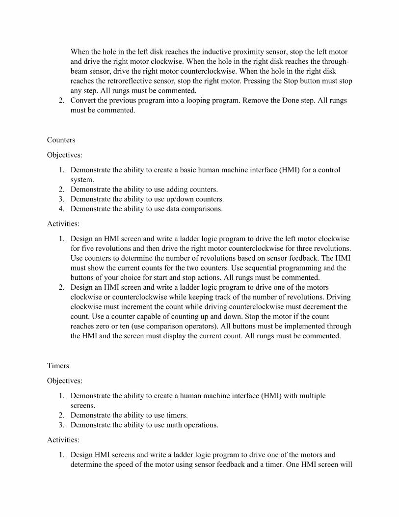
When the hole in the left disk reaches the inductive proximity sensor, stop the left motor and drive the right motor clockwise. When the hole in the right disk reaches the through-beam sensor, drive the right motor counterclockwise. When the hole in the right disk reaches the retroreflective sensor, stop the right motor. Pressing the Stop button must stop any step. All rungs must be commented.
2. Convert the previous program into a looping program. Remove the Done step. All rungs must be commented.
Counters
Objectives:
1. Demonstrate the ability to create a basic human machine interface (HMI) for a control system.
2. Demonstrate the ability to use adding counters. 3. Demonstrate the ability to use up/down counters. 4. Demonstrate the ability to use data comparisons.
Activities:
1. Design an HMI screen and write a ladder logic program to drive the left motor clockwise for five revolutions and then drive the right motor counterclockwise for three revolutions. Use counters to determine the number of revolutions based on sensor feedback. The HMI must show the current counts for the two counters. Use sequential programming and the buttons of your choice for start and stop actions. All rungs must be commented.
2. Design an HMI screen and write a ladder logic program to drive one of the motors clockwise or counterclockwise while keeping track of the number of revolutions. Driving clockwise must increment the count while driving counterclockwise must decrement the count. Use a counter capable of counting up and down. Stop the motor if the count reaches zero or ten (use comparison operators). All buttons must be implemented through the HMI and the screen must display the current count. All rungs must be commented.
Timers
Objectives:
1. Demonstrate the ability to create a human machine interface (HMI) with multiple screens.
2. Demonstrate the ability to use timers. 3. Demonstrate the ability to use math operations.
Activities:
1. Design HMI screens and write a ladder logic program to drive one of the motors and determine the speed of the motor using sensor feedback and a timer. One HMI screen will

allow the user to set the number of revolutions to run the motor for a test. The other HMI screen will start or abort the test and display the current time and current revolution counts along with the speed.
Analog Ultrasonic Distance Sensor
Objectives:
1. Demonstrate the ability to read an analog sensor. 2. Demonstrate the ability to calibrate an analog sensor. 3. Demonstrate the ability to convert raw analog input into a value with appropriate unit of
measure.
Activities:
1. Configure the analog input. 2. Design HMI screens and write ladder logic program to calibrate an analog ultrasonic
distance sensor and convert raw reading to millimeters and inches.
Closed-Loop Control
Objectives:
1. Demonstrate the ability to control a system using the On/Off mode of control. 2. Demonstrate the ability to control a system using the Proportional mode of control.
Activities:
1. Configure high speed inputs to read motor speed from encoder inputs. 2. Write ladder logic program to control motor using on/off control. 3. Write ladder logic program to control motor using proportional control.
Proportional-Integral-Derivative (PID) Tuning
Objectives:
1. Demonstrate the ability to tune a PID control system. 2. Demonstrate the ability to control a system using PID control.
Activities:
1. Using the Ziegler-Nichols Reaction Curve method, determine the parameters for PID control of motor speed.
2. Write a ladder logic program to control motor speed using PID control.