on the seakeeping operability of naval ships - …nausivios.snd.edu.gr/docs/c8_2010.pdf · the...
TRANSCRIPT

PaperID: NCH-2010-C8, Nausivios Chora 2010, Copyright © 2006-2010: Hellenic Naval Academy
1
On the Seakeeping Operability of Naval Ships
Gregory J. Grigoropoulos
aNational Technical University of Athens, School of Naval Architecture and Marine Engineering 9 Heroon Polytechniou str., 15773 Zografou, Greece
Abstract. The operability of a vessel in the sea environment, i.e. the capability to accomplish its mission is a major performance indicator of the vessel. It is well known that adverse sea conditions induce significant dynamic motions, velocities, accelerations and loads, which deteriorate the performance of both the crew and the various subsystems onboard, including the hull form itself. For example, the operation of medium and large naval ships e.g. destroyers, frigates and corvettes depends highly on the capability of the helicopters onboard to take-off and, more important to land. Otherwise, they are vulnerable to the attack of submarines. In severe wind and sea conditions and in order to ensure a convenient air wake field operation of helicopters, the captains use to manoeuvre their vessel so that they sail in quartering to following sea conditions. Furthermore, the specifications of the helicopters operating on board ships provide maximum acceptable values (criteria) which should not be violated in order the take-off and landing procedures are safe. Thus, the operation of the aircraft and especially the helicopters depends on the motions of the vessels in a seaway. In this paper, the current practice in the design and operation of naval ships to ensure its operational availability in specified sea conditions will be analyzed and the pertinent existing criteria will be reviewed. Additional information contained in NATO STANAG 4154 will be discussed and a framework of procedures to satisfy all involved subsystems will be proposed. Available methods to improve the performance of existing vessels or new designs will be presented and discussed.
Keywords: operability, seakeeping, naval ships, criteria. PACS: 02.30.Nw, 02.50.Fz, 02.60.Pn, 02.70.Hm, 04.30.Nk
INTRODUCTION
Following the pioneering works of Ursell (1949a, 1949b) [1], [2] on the two-dimensional motions of a cylinder in waves, Korvin-Kroukovsky (1955) [3] developed the first practical method to predict analytically the seakeeping performance of a ship in waves. The method denoted as strip theory is based on the two-dimensional hydrodynamic characteristics of the ship’s sections and it is widely used for the evaluation of the seakeeping qualities of ships. The latter are either mapped to circular sections to implement Ursell’s solutions, using Lewis (Lewis, 1929) [4] or Extended-Lewis (Athanassoulis and Loukakis, 1982) [5] conformal mapping techniques or are fitted with sources along the wetted contour (Frank, 1967) [6]. Later on, more exact and rigorous versions of the strip theory, as well as alternative two-dimensional techniques have been proposed. Their presentation, however, is outside the scope of this paper.

PaperID: NCH-2010-C8, Nausivios Chora 2010, Copyright © 2006-2010: Hellenic Naval Academy
2
In the 80s three-dimensional theories for zero speed were developed (Guevel and Bougis, 1982) [7] were developed. The forward speed in that case is treated in the same way as in the strip theory. At the same time fully three-dimensional methods were proposed, using either the translating and pulsating Kelvin source (see e.g. Liapis, 1986 [8]), which satisfies the free surface condition, or the simple Rankine source (Sclavounos, 1996 [9]). The latter methods provide more promising results.
By means of the above theories the seakeeping responses in regular waves are estimated. The more interesting dynamic behavior in realistic seaways is derived on the basis of the regular wave results using the methodology described in the pioneering paper of St. Denis and Pierson (1953) [10].
The assessment of the seakeeping performance leads to the following very interesting applications for both commercial and naval ships: • The evaluation of the ability of the ship to accomplish his service in a specific sea
environment. • The overall potential of the vessel to operate in the sea conditions that it is expected to
encounter throughout its life cycle. • The evaluation of alternative routes, especially for ocean going merchant vessels to conclude
to the optimum one, along which the deterioration of the performance of the vessel is kept to a minimum.
• The optimization of the hull form to exhibit best seakeeping behavior without deterioration of the other performance characteristics. Excluding the third of these applications which refers mainly to merchant ships, the remaining
ones will be discussed in detail in the sequel.
SEAKEEPING OPERABILITY PERFORMANCE ASSESSMENT
On the basis of the theoretical background, shortly described in the introduction, the seakeeping responses of a ship in specific sea conditions are assessed. Since the sea environment is of statistical nature ship responses, randomly occurring events and human response are expressed via statistical quantities, too. Approximate statistical relations exist between the responses and their probability, in the short term. Equivalence can be assumed between statistical and spectral definitions. To specify whether a vessel can operate in a given sea environment, the designer has to compare each dynamic response with one or more seakeeping criteria. These criteria are limiting values derived on the basis of experience, good practice and systematic trials to establish the threshold between operability and non-operability (failure to operate) of the vessel as a whole or any of the systems onboard.
Usually the root mean square (RMS) values are used to evaluate the severity of the dynamic responses, while the randomly occurring events are described via their frequency of appearance per hour. Recently, additional criteria referring to the well being of the personnel as well as their capability to accomplish their assigned tasks are suggested. The motion sickness incidence (MSI) and the motion induced interruption (MII) indices are to most common of them. The former declares the percentage of personnel that suffers of motion sickness, nausea etc. while the latter focuses on the ability of a crew member to move from one location to another one aboard without many interruptions. These indices are calculated by correlating the performance of the humans with the dynamic responses of the ship [11, 12].
Regarding the establishment of seakeeping criteria, significant work, both for merchant and naval ships, as well as small craft has been reported by the NORDIC Project [13]. The criteria that are associated with the hull of naval ships, as well as the subsystems onboard and the personnel comfort are presented in STANAG 4154, 3rd Edition (2000) [14], issued by NATO.
PaperID: NCH-2010-C8, Nausivios Chora 2010, Copyright © 2006-2010: Hellenic Naval Academy
3
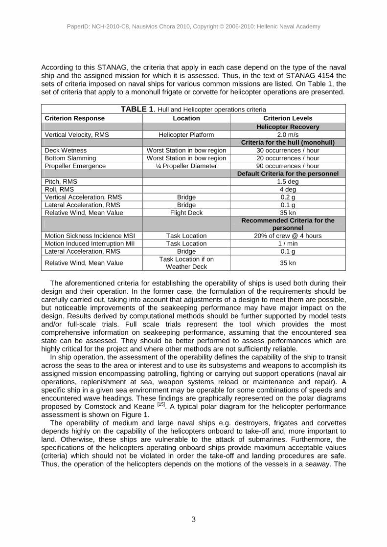
According to this STANAG, the criteria that apply in each case depend on the type of the naval ship and the assigned mission for which it is assessed. Thus, in the text of STANAG 4154 the sets of criteria imposed on naval ships for various common missions are listed. On Table 1, the set of criteria that apply to a monohull frigate or corvette for helicopter operations are presented.
TABLE 1. Hull and Helicopter operations criteria Criterion Response Location Criterion Levels Helicopter Recovery Vertical Velocity, RMS Helicopter Platform 2.0 m/s Criteria for the hull (monohull) Deck Wetness Worst Station in bow region 30 occurrences / hour Bottom Slamming Worst Station in bow region 20 occurrences / hour Propeller Emergence ¼ Propeller Diameter 90 occurrences / hour Default Criteria for the personnel Pitch, RMS 1.5 deg Roll, RMS 4 deg Vertical Acceleration, RMS Bridge 0.2 g Lateral Acceleration, RMS Bridge 0.1 g Relative Wind, Mean Value Flight Deck 35 kn
Recommended Criteria for the
personnel Motion Sickness Incidence MSI Task Location 20% of crew @ 4 hours Motion Induced Interruption MII Task Location 1 / min Lateral Acceleration, RMS Bridge 0.1 g
Relative Wind, Mean Value Task Location if on
Weather Deck 35 kn
The aforementioned criteria for establishing the operability of ships is used both during their
design and their operation. In the former case, the formulation of the requirements should be carefully carried out, taking into account that adjustments of a design to meet them are possible, but noticeable improvements of the seakeeping performance may have major impact on the design. Results derived by computational methods should be further supported by model tests and/or full-scale trials. Full scale trials represent the tool which provides the most comprehensive information on seakeeping performance, assuming that the encountered sea state can be assessed. They should be better performed to assess performances which are highly critical for the project and where other methods are not sufficiently reliable.
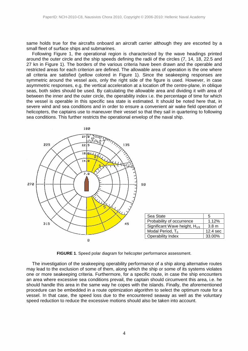
In ship operation, the assessment of the operability defines the capability of the ship to transit across the seas to the area or interest and to use its subsystems and weapons to accomplish its assigned mission encompassing patrolling, fighting or carrying out support operations (naval air operations, replenishment at sea, weapon systems reload or maintenance and repair). A specific ship in a given sea environment may be operable for some combinations of speeds and encountered wave headings. These findings are graphically represented on the polar diagrams proposed by Comstock and Keane [15]. A typical polar diagram for the helicopter performance assessment is shown on Figure 1.
The operability of medium and large naval ships e.g. destroyers, frigates and corvettes depends highly on the capability of the helicopters onboard to take-off and, more important to land. Otherwise, these ships are vulnerable to the attack of submarines. Furthermore, the specifications of the helicopters operating onboard ships provide maximum acceptable values (criteria) which should not be violated in order the take-off and landing procedures are safe. Thus, the operation of the helicopters depends on the motions of the vessels in a seaway. The
PaperID: NCH-2010-C8, Nausivios Chora 2010, Copyright © 2006-2010: Hellenic Naval Academy
4
same holds true for the aircrafts onboard an aircraft carrier although they are escorted by a small fleet of surface ships and submarines.
Following Figure 1, the operational region is characterized by the wave headings printed around the outer circle and the ship speeds defining the radii of the circles (7, 14, 18, 22.5 and 27 kn in Figure 1). The borders of the various criteria have been drawn and the operable and restricted areas for each criterion are defined. The allowable area of operation is the one where all criteria are satisfied (yellow colored in Figure 1). Since the seakeeping responses are symmetric around the vessel axis, only the right side of the figure is used. However, in case asymmetric responses, e.g. the vertical acceleration at a location off the centre-plane, in oblique seas, both sides should be used. By calculating the allowable area and dividing it with area of between the inner and the outer circle, the operability index i.e. the percentage of time for which the vessel is operable in this specific sea state is estimated. It should be noted here that, in severe wind and sea conditions and in order to ensure a convenient air wake field operation of helicopters, the captains use to maneuver their vessel so that they sail in quartering to following sea conditions. This further restricts the operational envelop of the naval ship.
FIGURE 1. Speed polar diagram for helicopter performance assessment. The investigation of the seakeeping operability performance of a ship along alternative routes
may lead to the exclusion of some of them, along which the ship or some of its systems violates one or more seakeeping criteria. Furthermore, for a specific route, in case the ship encounters an area where excessive sea conditions prevail, the captain should circumvent this area, i.e. he should handle this area in the same way he copes with the islands. Finally, the aforementioned procedure can be embedded in a route optimization algorithm to select the optimum route for a vessel. In that case, the speed loss due to the encountered seaway as well as the voluntary speed reduction to reduce the excessive motions should also be taken into account.
Sea State 5 Probability of occurrence 1.12% Significant Wave height, H1/3 3.8 m Modal Period, T0 12.4 sec Operability Index 33.00%

PaperID: NCH-2010-C8, Nausivios Chora 2010, Copyright © 2006-2010: Hellenic Naval Academy
5
OPERATIONAL EFFECTIVENESS FOR SEAKEEPING
Operational effectiveness refers to the ability of the ship to accomplish its mission in whatever conditions it may encounter [11]. In order to estimate the operational effectiveness of a naval ship for seakeeping, the whole procedure described in the previous section, is repeated for a set of sea states expected to meet during its mission. Furthermore, it is combined with the probability of encountering each sea condition on the way to accomplish its assigned mission. To this end, the designer makes use of the available statistical data for each sea area, providing the frequency of occurrence of each combination of significant wave height H1/3, modal period T0 and wave direction θ in the area. This data are available in annual, seasonal or monthly basis. By combining the aforementioned statistical characteristics of the sea area, with the expected speeds and route of the vessel, when it crosses the area and with the operability properties of the vessel for each sea condition the respective statistical information regarding the annual, seasonal or monthly operational effectiveness of the vessel is assessed. The method can be extended to life-cycle calculations for the ship. In Figure 2, a typical conditional frequency distribution of sea area, farea, for a naval ship operating in North Atlantic during given seasons is shown. In this Figure, sea areas are defined according to Hogben et al (1986) [16].
Winter
Autumn
Summer
Spring
Sea Area 1 2 3 4 8 9 10 11 15 16 17 23 24 25 fseason
FIGURE 2. Typical conditional frequency distribution of sea area, farea, for a naval ship in North Atlantic, during given seasons.
FIGURE 3. Typical conditional frequency distributions of speed, fU, along given courses of a naval ship.

PaperID: NCH-2010-C8, Nausivios Chora 2010, Copyright © 2006-2010: Hellenic Naval Academy
6
In Figure 3 the conditional frequency distributions of speed, fU, along given courses of a naval ship are depicted. All courses are equally likely, and a wide range of speeds is demanded. Nevertheless, the economical cruising speed is frequently used. Very high or very low speeds are rare.
FIGURE 4. Calculation of the operational effectiveness (Andrew et al, 1984).
On the basis of the aforementioned information a simplified version of the method proposed by Andrew et al (1984) [17] is used to estimate the operational effectiveness. The calculation is illustrated in graphical form in Figure 4. The operating environment is specified in terms of the scatter diagram of seasons and sea areas as already shown in Figure 2. For each combination of sea area and season we can use a wave atlas [18] to obtain the conditional frequency distribution of the wave directions fx and the joint frequency distribution of the modal periods T0 and significant wave heights H1/3, fTH. Subsequently, we for each sea state we can calculate the dynamic ship responses for all possible combinations of ship course and speed. The required heading is derived from the wave directions and the ship courses. In case one or more seakeeping criteria are exceeded, the ship can not accomplish its mission.
The proportion of time spent in a given season, sea area, wave direction, modal period, significant wave height, speed and course is defined by following relation:
P = fseason farea fx fTH fcourse fU (1)
where,
fseason the frequency distribution of season, farea the conditional frequency distribution of the sea areas where the ship operates during a
given season, fx the conditional frequency distribution of the primary wave directions relative to North, for
the given season and sea area,

PaperID: NCH-2010-C8, Nausivios Chora 2010, Copyright © 2006-2010: Hellenic Naval Academy
7
fTH the joint frequency distribution of modal periods and significant wave heights for the given season, sea area and wave direction,
fcourse the frequency distribution of the ship course relative to North, and fU the conditional frequency distribution of the ship speed for a given ship course.
The ship is capable of accomplishing its mission if all the responses don’t violate any of the
seakeeping criteria imposed for the mission being considered. The proportion of time for which this is the case, is obtained from the weighted sum of all the possible values of P. This may be written as:
Ε = Σseason Σarea Σx ΣTH Σcourse ΣU (P Γ1 Γ2 Γ3 - - - ΓΝ) (2)
where the symbol Σ declares summation over the subscript, i.e. Σseason, declares summation over all four seasons. ΓΝ is a cumulative function defined by: Γn = 1 for rn < rncrit Γn = 0 for rn > rncrit (3)
where rn is the nth response and rncrit is its limiting value.
OPTIMIZATION FOR SEAKEEPING
Thirty years ago, Bales (1980) [18] used analytical seakeeping results to derive a regression formula correlating the performance of Destroyer-type hull forms in head seas and at various speeds to certain empirically selected hull form parameters. Then, he used this formula to find the optimum combination of these form parameters which minimize the seakeeping responses. Grigoropoulos and Loukakis (1988) [19] presented a more general method for developing hull forms with superior seakeeping qualities. The method, described by Grigoropoulos (1989) [20], was used for the analytical development of an optimized hull form for a reefer ship, the efficiency of the method was experimentally verified by model tests of both the parent and the optimum hull.
The method demonstrated that there is also room for considerable seakeeping improvements even when the displacement and the principal characteristics of a new design have been determined without any seakeeping considerations. The methodology can either be incorporated directly in the preliminary design spiral or it can be used to modify a parent hull form. In the assessment of the seakeeping operability the main aim is to ensure that a specific dynamic response of the hull form does not violate a specific seakeeping criterion at a given speed and in specified sea conditions. On the contrary, the objective of the proposed optimization methodology is to ascertain that a ship, designed with a very complex objective function and many practical constraints in mind, will have as good seakeeping qualities as possible.
The hull form is described in adequate detail for seakeeping calculations, but in a simple manner to allow for the automatic generation of the many variants required by the optimization scheme. Thus, the hull form is considered to be known if the following characteristics are specified: the main dimensions: length between perpendiculars LBP, breadth B and draught T, the sectional area curve S(x), the waterline curve B(x), the longitudinal profile curve Z(x) and the curve of the longitudinal distribution of the centroid of the ship sections KB(x) [5]. From these curves, all necessary ship design parameters can be derived i.e. the displacement ∆, the form parameters CB, CP, CM, CVP, CWP, the location of centers LCB, LCF, KB etc.
PaperID: NCH-2010-C8, Nausivios Chora 2010, Copyright © 2006-2010: Hellenic Naval Academy
8
The optimization process is based on the automatic generation of variants of a parent hull form with varying one or more of the design parameters, using an extension of Lackenby method [21], to accommodate waterlines and sectional area curves of any shape. To obtain an optimum solution a figure of merit should be specified. The method is based on the assertion: “Ship responses at sea are minima when the corresponding peak value of their Response Amplitude Operator (RAO) is minimized” and that, “therefore, seakeeping optimization can be achieved on the basis of regular wave results only”. This statement has been numerically verified for ships with displacement and dimensions close to those of the parent hull form. Then, the optimization problem reduces to the following:
“Find the variant with the optimum seakeeping performance of a parent hull form, described by a set of four curves S(x), B(x), Z(x) and KB(x) and identified by a set of design variables (LBP, B, T, CB, CWP, LCB, LCF, KB) under given constraints.”
Seakeeping performance is expressed as the weighted sum of the peak values of a prescribed set of ship responses in regular waves, for various ship speeds and headings. Optimum performance corresponds to the minimum value of this sum, which is the objective function of the problem. Hydrostatic, stability and common design practice equality and inequality constraints are imposed to the problem which is characterized by the experimentally verified unimodality of the bell-shaped objective function. The direct optimization method proposed by Hooke and Jeeves (1961) [22] in conjunction with the External Penalty Function Method [23], to convert the constrained optimization problem to an unconstrained one, are used to solve the problem.
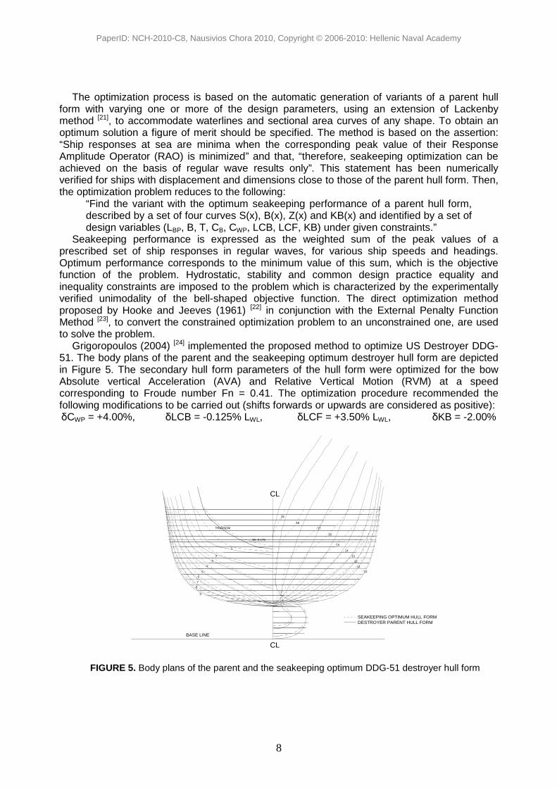
Grigoropoulos (2004) [24] implemented the proposed method to optimize US Destroyer DDG- 51. The body plans of the parent and the seakeeping optimum destroyer hull form are depicted in Figure 5. The secondary hull form parameters of the hull form were optimized for the bow Absolute vertical Acceleration (AVA) and Relative Vertical Motion (RVM) at a speed corresponding to Froude number Fn = 0.41. The optimization procedure recommended the following modifications to be carried out (shifts forwards or upwards are considered as positive): δCWP = +4.00%, δLCB = -0.125% LWL, δLCF = +3.50% LWL, δKB = -2.00%
BASE LINE
9
8
TRANSOM
2
4
5
6
7
3
WL-9.175
1
18
CL
12
13
14
15
16
17
DESTROYER PARENT HULL FORMSEAKEEPING OPTIMUM HULL FORM
10
11
CL
19
FIGURE 5. Body plans of the parent and the seakeeping optimum DDG-51 destroyer hull form
PaperID: NCH-2010-C8, Nausivios Chora 2010, Copyright © 2006-2010: Hellenic Naval Academy
9
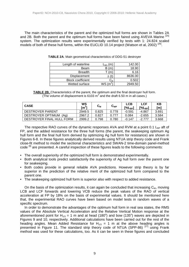
The main characteristics of the parent and the optimized hull forms are shown in Tables 2A and 2B. Both the parent and the optimum hull forms have been faired using AVEVA Marine [25] system. The optimization results were experimentally verified by tests with 1: 24.824 scaled models of both of these hull forms, within the EUCLID 10.14 project (Watson et al, 2002) [26].
TABLE 2A. Main geometrical characteristics of DDG-51 destroyer
Length of waterline LWL (m) 142.00 Beam B (m) 18.90
Breadth T (m) 6.16 Displacement ∆ (t) 8636.00
Block coefficient CB 0.502 Wetted surface WS (m2) 2949.50
TABLE 2B. Characteristics of the parent, the optimum and the final destroyer hull form.
(The volume of displacement is 6103 m3 and the draft 6.50 m in all cases.)
CASE WS [m2] CM CWP LCB
[%LBP] LCF
[%LBP] KB [m]
DESTROYER PARENT 2949.5 0.825 0.778 -0.591 -4.867 3.691 DESTROYER OPTIMUM (Ag) 2967.2 0.827 0.777 0.084 -2.655 3.584 DESTROYER FINAL HULL FORM 2999.2 0.798 0.780 -0.147 -2.777 3.668
The respective RAO curves of the dynamic responses AVA and RVM at a point 0.1 LBP aft of
FP, and the added resistance for the three hull forms (the parent, the seakeeping optimum Ag hull form and the final hull form derived by optimizing Ag hull form for resistance) are shown in Figures 6-8. In these figures analytically derived results using NTUA strip theory code and Frank close-fit method to model the sectional characteristics and SWAN-2 time-domain panel-method code [9] are presented. A careful inspection of these figures leads to the following comments:
• The overall superiority of the optimized hull form is demonstrated experimentally. • Both analytical tools predict satisfactorily the superiority of Ag hull form over the parent one
for seakeeping. • Both codes provide in general reliable AVA predictions. However strip theory is by far
superior in the prediction of the relative merit of the optimized hull form compared to the parent one.
• The seakeeping optimized hull form is superior also with respect to added resistance. On the basis of the optimization results, it can again be concluded that increasing CW, moving
LCB and LCF forwards and lowering VCB reduce the peak values of the RAO of vertical acceleration at FP by 18% on the basis of experimental values. It should be mentioned here that, the experimental RAO curves have been based on model tests in random waves of a specific spectrum.
In order to demonstrate the advantages of the optimum hull form in real sea states, the RMS values of the Absolute Vertical Acceleration and the Relative Vertical Motion response at the aforementioned point for H1/3 = 1 m and at head (180o) and bow (135o) waves are depicted in Figures 9 and 10, respectively. Additional calculations have been carried out for the rest of the heading angles. Mean Added Resistance for H1/3 = 1 m at the above heading angles is presented in Figure 11. The standard strip theory code of NTUA (SPP-86) [27] using Frank method was used for these calculations, too. As it can be seen in these figures and concluded

PaperID: NCH-2010-C8, Nausivios Chora 2010, Copyright © 2006-2010: Hellenic Naval Academy
10
from the additional calculations, the superiority of the optimized hull form is apparent at the longer modal periods, corresponding to severe seas, and all headings, whereas the optimization was carried out for head seas.
Predictions
0
10
20
30
40
50
60
70
0.5 1.5 2.5 3.5
λ/L
Abs
. Ver
t. A
ccel
erat
ion
ampl
itude
*L /
(ga)
PARENT-Frank
PARENT-SW AN2
Ag-Frank
Ag-SW AN2
Model Tests
0
10
20
30
40
50
60
70
0,5 1,5 2,5 3,5
λ/L
Abs
. Ver
t. A
ccel
erat
ion
ampl
itude
*L /
(ga)
PARENT-EXP
Ag-EXP
FIGURE 6. Analytical and experimental results for the RAO curve of bow AVA of the parent and the
seakeeping optimum destroyer-type hull forms (Fr. No. = 0.41).
Predictions
0
0.5
1
1.5
2
2.5
3
3.5
4
4.5
5
0 0.5 1 1.5 2 2.5 3 3.5 4 4.5 5
λ/L
Rel
. Ver
t. M
otio
n am
plitu
de /
a
PARENT-Frank
PARENT-SWAN2
Ag-Frank
Ag-SWAN2
FIGURE 7. Analytical results for the RAO curve of bow RVM of the parent and the seakeeping
optimum destroyer-type hull forms (Fr. No. = 0.41).

PaperID: NCH-2010-C8, Nausivios Chora 2010, Copyright © 2006-2010: Hellenic Naval Academy
11
Predictions
0
2
4
6
8
10
12
14
16
18
0 0.5 1 1.5 2 2.5 3 3.5 4 4.5 5
λ/L
Mea
n A
dded
Res
ista
nce
/ (ρ
gB2 a2 /L
)
PARENT-Frank
Ag-Frank
FIGURE 8. Analytical results for the RAO curve of added resistance in head waves of the parent and
the seakeeping optimum destroyer-type hull forms (Fr. No. = 0.41).
CFD Caclulations
0
0.1
0.2
0.3
0.4
0.5
0.6
4 5 6 7 8 9 10 11 12 13
Tp [sec]
RM
S A
bs. V
ert.
Acc
eler
atio
n in
the
bow
reg
ion
[m/s
ec2/m
]
PARENT-180
PARENT-135
OPTIMUM-180
OPTIMUM-135
FIGURE 9. RMS Absolute Vertical Acceleration / H1/3 of the in the bow region (0.1 LBP aft of FP), for the parent and the seakeeping optimum destroyer-type hull forms (Fn = 0.41).

PaperID: NCH-2010-C8, Nausivios Chora 2010, Copyright © 2006-2010: Hellenic Naval Academy
12
Predictions
0
0.1
0.2
0.3
0.4
0.5
0.6
0.7
4 5 6 7 8 9 10 11 12 13
Tp [sec]
RM
S R
el. V
ert.
Mot
ion
at 1
0% a
ft of
FP
[m/m
]
PARENT-180
PARENT-135
OPTIMUM-180
OPTIMUM-135
FIGURE 10. RMS Relative Vertical Motion / H1/3 of the in the bow region (0.1 LBP aft of FP) for the parent and the seakeeping optimum destroyer-type hull forms (Fn = 0.41).
Predictions
0
500
1000
1500
2000
2500
4 5 6 7 8 9 10 11 12 13
Tp [sec]
Mea
n A
dded
Res
ista
nce
[Kp/
m2 ]
PARENT-180
PARENT-135
OPTIMUM-180
OPTIMUM-135
FIGURE 11. Mean Added Resistance / H1/3 for the parent and the seakeeping optimum destroyer-type
hull forms (Fn = 0.41).
PaperID: NCH-2010-C8, Nausivios Chora 2010, Copyright © 2006-2010: Hellenic Naval Academy
13
Advanced Multi-Objective Optimization for Seakeeping
The aforementioned described procedure is very fast and powerful. However, it has two drawbacks: 1. Although the method is very robust in providing the trends in the design parameters for
improving seakeeping performance, the final outcome of the optimization procedure is not a fair and realistic hull form. Fairing by a CAD software is needed which partly reduces the advantages of the optimum combination of design parameters.
2. In case more than one discipline is to be optimized, a weighted sum of the measures of merits for each discipline is used as objective function. The weighting factors actually impose the relative significance of each of the disciplines and the final outcome may not be quite optimum for each one of the disciplines. In order to remedy these drawbacks and to exploit new tools available during the last decade
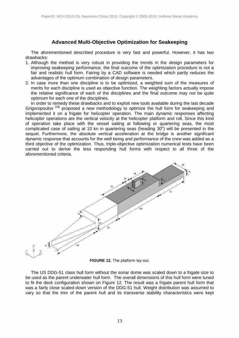
Grigoropoulos [28] proposed a new methodology to optimize the hull form for seakeeping and implemented it on a frigate for helicopter operation. The main dynamic responses affecting helicopter operations are the vertical velocity at the helicopter platform and roll. Since this kind of operation take place with the vessel sailing at following or quartering seas, the most complicated case of sailing at 10 kn in quartering seas (heading 30o) will be presented in the sequel. Furthermore, the absolute vertical acceleration at the bridge is another significant dynamic response that accounts for the well being and performance of the crew was added as a third objective of the optimization. Thus, triple-objective optimization numerical tests have been carried out to derive the less responding hull forms with respect to all three of the aforementioned criteria.
FIGURE 12. The platform lay-out.
The US DDG-51 class hull form without the sonar dome was scaled down to a frigate size to
be used as the parent underwater hull form. The overall dimensions of this hull form were tuned to fit the deck configuration shown on Figure 12. The result was a frigate parent hull form that was a fairly close scaled-down version of the DDG-51 hull. Weight distribution was assumed to vary so that the trim of the parent hull and its transverse stability characteristics were kept

PaperID: NCH-2010-C8, Nausivios Chora 2010, Copyright © 2006-2010: Hellenic Naval Academy
14
constant along the runs. Main dimensions (LBP and B) were kept fixed during the optimization, while small variations of draft T were only allowed to counterbalance the deviation of the displacement due to the variation of the hull form and limit it within 1% of its initial value. The main particulars of this hull form are presented on Table 3.
TABLE 3. Main particulars of the parent hull form
Main Characteristic Symbol Value Length Overall LOA [m] 145 Length Between Perpendiculars LBP [m] 140 Breadth maximum B [m] 19.19 Draught design T [m] 6.16 Volume of Displacement ∆ [m3] 8274.6 Waterplane area AWP [m2] 1456.5 Wetted Surface WS [m2] 2798.3 Long. Centre of Flotation LCF [m] 67.3 Long. Centre of Buoyancy LCB [m] 69.0 Block Coefficient CB [-] 0.500 Prismatic Coefficient CP [-] 0.614
The methodology implements Friendship-Modeller, as described by Abt et al (2001) [29], to
represent hull form parametrically. The modelling procedure encompasses three steps: o Parametric design of the basic longitudinal curves o Parametric modelling of the design stations (vertical / lateral curves) on the basis of the
longitudinal ones. o Development of surfaces (patches) to interpolate the design stations.
FORE AFT
PART PART
Actual Hull
Parametric Representation
FIGURE 13. Parametric representation of the frigate hull form
The model of the parent hull form over the actual one has been plotted in Figure 13. Among
the more than 50 geometrical parameters involved in the modelling of the hull, the following eleven have been selected to vary either all or some of them, with specified limits for the optimization:
PaperID: NCH-2010-C8, Nausivios Chora 2010, Copyright © 2006-2010: Hellenic Naval Academy
15
1. SACcpForBody 2. SACcaForFrame 3. GSACareaCoeff 4. GSACxcbAft 5. TRANSECdraft 6. TRANSECtanAtCpc
7. TRANSECbeamAtDec 8. DWLtanAtBow 9. DWLareaCoeff 10. FOSforEnd 11. FOStanAtBow
These parameters encompass the shape of the flat of side and the flat of bottom, the freeboard, the deadrise angle, the centers of areas, the entrance and run lengths, and the parallel middle body. Their names are self-explanatory.
For the optimization an Evolutionary Strategy (ES) is used, as implemented by EASY v.2.0 system. The method is described in its User Manual, as well as by Karakasis et al (2003) [30]. The following parameters of the ES were used: o Offspring population size: 25 o Parent population size: 6 o Parent of one offspring: 3 o Maximum generations/evaluations: 20/500 o Elite archive size: 4 o Maximum idle generations/evaluations: 4/15
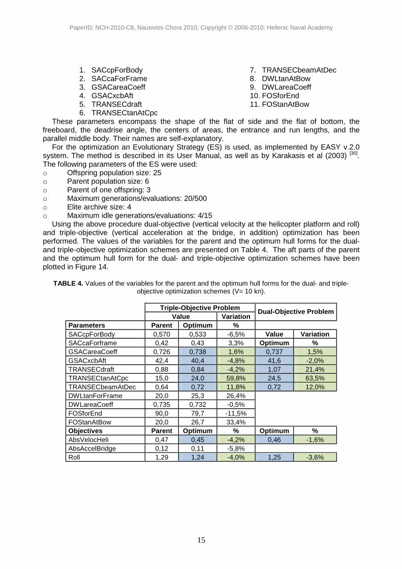
Using the above procedure dual-objective (vertical velocity at the helicopter platform and roll) and triple-objective (vertical acceleration at the bridge, in addition) optimization has been performed. The values of the variables for the parent and the optimum hull forms for the dual- and triple-objective optimization schemes are presented on Table 4. The aft parts of the parent and the optimum hull form for the dual- and triple-objective optimization schemes have been plotted in Figure 14.
TABLE 4. Values of the variables for the parent and the optimum hull forms for the dual- and triple-objective optimization schemes (V= 10 kn).
Triple-Objective Problem Value Variation
Dual-Objective Problem
Parameters Parent Optimum % SACcpForBody 0,570 0,533 -6,5% Value Variation SACcaForframe 0,42 0,43 3,3% Optimum % GSACareaCoeff 0,726 0,738 1,6% 0,737 1,5% GSACxcbAft 42,4 40,4 -4,8% 41,6 -2,0% TRANSECdraft 0,88 0,84 -4,2% 1,07 21,4% TRANSECtanAtCpc 15,0 24,0 59,8% 24,5 63,5% TRANSECbeamAtDec 0,64 0,72 11,8% 0,72 12,0% DWLtanForFrame 20,0 25,3 26,4% DWLareaCoeff 0,735 0,732 -0,5% FOSforEnd 90,0 79,7 -11,5% FOStanAtBow 20,0 26,7 33,4% Objectives Parent Optimum % Optimum % AbsVelocHeli 0,47 0,45 -4,2% 0,46 -1,6% AbsAccelBridge 0,12 0,11 -5,8% Roll 1,29 1,24 -4,0% 1,25 -3,6%

PaperID: NCH-2010-C8, Nausivios Chora 2010, Copyright © 2006-2010: Hellenic Naval Academy
16
FIGURE 14. Aft part of the parent and optimum hull form for the dual- and triple-objective optimization schemes.
Following the results of Table 4, improvements of the order of 4-5% in all three responses are achieved when all 11 design parameters are varied. For comparison purposes, the respective results for the dual-objective optimization (excluding AVA at the bridge), where only five of the design variables are modified, are presented. In this case the optimum values for the two objectives are less than in the former case.
CONCLUSIONS AND RECOMMENDATIONS
In this paper, the theoretical background and the tools available to the designer and the operator to carry out seakeeping calculations are presented.
The designer, equipped with these tools is able to assess the dynamic response of any ship in a specific seaway. In order to evaluate the operability of a ship in a seaway, a set of seakeeping criteria should be specified which depend on the mission of the ship. The ship is considered as operable in any sea state where all set criteria are satisfied. The emphasis of the respective discussion was on medium and large naval ships, which operate at least one helicopter for anti-submarine warfare.
Furthermore, the hull form of any naval ship can be significantly improved with respect to seakeeping, if it undergoes an optimization procedure. Two alternative methodologies were presented in this respect, the more traditional one where the combination of some hull form parameters is sought which minimizes the seakeeping performance of the corresponding vessel. However, since this procedure does not result in a fair hull form, an a posteriori fairing is carried out which partly reduces the benefits of the optimization. Anyway the whole procedure is robust and results in quite improved hull forms.
Recently, some modern tools became available to the designer (parametric modelling, genetic algorithms), that allow for a more general multi-objective methodology. A complicated test case implementing this methodology is described to demonstrate the potential of the method.
The main intention of the author is to demonstrate that currently plenty of powerful tools are available both to the designer and the operator that allow the incorporation of seakeeping
Parent Dual-Objective Optimiz. Tripple-Objective Optim.

PaperID: NCH-2010-C8, Nausivios Chora 2010, Copyright © 2006-2010: Hellenic Naval Academy
17
behavior in the design process and that these tools may result in a final product with significantly improved seakeeping characteristics even when the main dimensions and parameters are fixed. The evolution of computer power permits the execution of these complicated optimization procedures within reasonable computing time.
ACKNOWLEDGMENTS
The author would like to acknowledge HULLOPT (Optimal Techniques for Hull Geometry), EUCLID 10.14 Project sponsored by CEPA 10, for supporting this research and for permitting the publication of the results regarding DDG-51 and Ag hull. Greece, Italy, Turkey and United Kingdom participated in this project with industrial partners NTUA, INSEAN and FINCANTIERI, ITU and QINETIQ, respectively.
He also would like to thank Lieutenant Commander (HN) Emmanuel Chatzipanagiotou for carrying out the optimization computations within his thesis for the postgraduate program on Marine Science and Technology supervised by the author.
REFERENCES
1. F. Ursell, “On the Heaving Motion of a Circular Cylinder on the Surface of a Fluid”, Quart. Journal of Mech. And Appl. Maths, Vol. 2, p. 213, (1949a).
2. F. Ursell, “On the Rolling Motion of a Cylinders in the Surface of a Fluid”, Quart. Journal of Mech. and Applied Maths, Vol. 2, p. 335, (1949b).
3. B.V. Korvin-Kroukovsky and W.D. Jacobs, “Pitching and Heaving Motions of a Ship in Regular Waves”, Trans. SNAME, Vol. 65, p. 590, 1957.
4. F.M. Lewis, “The Inertia of Water Surrounding a Vibrating Ship”, Trans. SNAME, Vol. 37, p. 1, 1929. 5. G.A. Athanassoulis and T.A. Loukakis, “An Extended Lewis Form Family of Ship Sections and Its
Applications to Seakeeping Calculations”, Intl. Shipbuilding Progress, Vol.32, No.366, p.33, 1982. 6. W. Frank, “Oscillation of Cylinders in or Below the Free Surface of Deep Fluids”, NSRDC, Rep. No.
2375, Washington D.C. (1967). 7. P. Guevel and J. Bougis, “Ship Motions with Forward Speed in Infinite Depth”, Intl. Shipbuilding
Progress, Vol. 29, No. 332, p.103, Apr. 1982. 8. S.J. Liapis, “Time Domain Analysis of Ship Motions”, Technical Report 302, Department of Naval
Architecture and Marine Engineering, The University of Michigan, Ann Arbour, 1986. 9. P.D. Sclavounos, “Computation of Wave Ship Interactions”, Advances in marine hydrodynamics,
edited by Qhkusu M., Computational Mechanics Publications, 1996. 10.M. St. Denis and W.J. Pierson, “On the Motions of Ships in Confused Seas”, Trans. SNAME, Vol. 61,
p. 280, 1953. 11.A.R.J.M. Lloyd, “Seakeeping: Ship Behaviour in Rough Weather”, Ellis Horwood Ltd Publ., John Wiley
& Sons, New York, 1989. 12.International Organization of Standardization ISO, “Mechanical Vibration and Shock: Evaluation of
Human Exposure to Whole-Body Vibration. Part 1: General Requirements”, ISO 2631-1, 1997. 13.NORDIC Project Board (1987), “Assessment of Ship Performance in a Seaway”, NORD-FORSK,
NORDIC Cooperative Project: Seakeeping performance of ships, Copenhagen Denmark. 14.STANAG 4154 NAV (EDITION 3), Common Procedures for Seakeeping in the Ship Design Process,
13 December 2000, MAS/1 5 14-NAVI4154 15.E.N. Comstock and R.G. Keane, “Seakeeping by Design”, Naval Engineering Journal, April 1980. 16.N. Hogben, N.M.C. Dacunha and G.F. Olliver, “Global Wave Statistics”, Publ. for British Maritime
Technology Ltd by Unwin Brothers Ltd, Feltham, Middlesex TW140LQ, ISBN 0946653380, 1986. 17.R.N. Andrew, P.R. Loader and V.E. Penn, “The Assessment of Ship Seakeeping Performance in Likely
to Be Encountered Wind and Wave Conditions, RINA Intl. Symposium On Wave and Wind Climate Worldwide, London, 1984.

PaperID: NCH-2010-C8, Nausivios Chora 2010, Copyright © 2006-2010: Hellenic Naval Academy
18
18.N.K. Bales, “Optimizing the Seakeeping Performance of Destroyer-Type Hulls”, 13th ONR Symposium on Naval Hydrodynamics, Tokyo, Japan, 1980.
19.G.J. Grigoropoulos and T.A. Loukakis, “A New Method for Developing Hull Forms with Superior Seakeeping Qualities”, CADMO‘88, Southampton, U.K, September 1988.
20.G.J. Grigoropoulos, “Hull Form Optimization with Respect to Seakeeping”, PhD Thesis, NTUA, Dept. of Naval Arch. and Marine Eng., Athens, Greece, May 1989.
21.H. Lackenby, “On the Systematic Geometrical Variation of Ship Forms”, Trans. INA, Vol. 92, p. 289, 1950.
22.R. Hooke R. and T.A. Jeeves, “Direct Search Solution of Numerical and Statistical Problems”, Journal of Assoc. for Computing Machinery, Vol.8, No.4, p. 212, 1961.
23.G.E. Wangdahl, “The External Penalty Function Optimization Technique and Its Application to Ship Design”, The Univ. of Michigan, Ann Arbor, Rep. No.129, 1972.
24.G.J. Grigoropoulos, “Hull Form Optimization for Hydrodynamic Performance”, Marine Technology, Vol. 41, No. 4, October 2004.
25.AVEVA Marine, “User’s Manual”, AVEVA Solutions Ltd, High Cross, Madingley Road, Cambridge, CB3 0HB, United Kingdom, September 2007.
26.S.J.P. Watson, C. Richardsen and M.C. Johnson, “Technical Report for EWP2 of HULLOPT”, EUCLID Project RPT 10.14/003 (Optimal Techniques for Hull Geometry), Vers. 0, QINETIQ, UK, February 2002.
27.”SPP-86: User Manual”, Lab. for Ship and Marine Hydrodynamics, National Technical Univ. of Athens, Athens, Greece, 1986.
28.G.J. Grigoropoulos, “Ship Motion Simulation”, in Modelling and Simulation of the Ship Environment for Safer Aircraft Launch and Recovery, NATO Technical Report RTO-TR-AVT-148, 2010, to appear.
29.C. Abt, S.D. Bade, L. Birk and S. Harries, “Parametric Hull Form Design – A Step Towards One Week Ship Design”, 8th Intl. Symp. on Practical Design of Ships and Other Floating Structures, PRADS 2001, Shanghai, 2001.
30.M.K. Karakasis, A.P. Giotis and K.C. Giannakoglou, “Inexact Information Aided, Low-cost, Distributed Genetic Algorithms for Aerodynamic Shape Optimization”, Intl. Journal for Numerical Methods in Fluids, 43, pp. 1149-1166, 2003.