open-jet wind tunnel at mach numbers - … · · 2011-05-14open-jet wind tunnel at mach numbers...
TRANSCRIPT
__ _ _- 6 - -_
AN EXPERIMENTAL INVESTIGATION OFFIXED-GEOMETRY DIFFUSERS IN AN
OPEN-JET WIND TUNNEL AT MACH NUMBERSBETWEEN 14 AND 18 AND REYNOLDS NUMBERS
BETWEEN 8,900 AND 25,000
James J. White, III
ARO, Inc.
March 1967 -1 ID C
MA~R 20 967
Distribution of this document is unlimited.
PROPULSION WIND TUNNEL FACILITY
ARNOLD ENGINEERING DEVELOPMENT CENTER
AIR FORCE SYSTEMS COMMAND
ARNOLD AIR FORCE STATION, TENNESSEE
JUSINrCAT .. ....
ByDf~RIurIN VAILAVILITY CODES
DIST I AVAIL, Ind/or SpECIAL
When U1. S. Government drawings specifications, or other data are used for any purpose other than adefinitely related Government procurement operation, the Gwvernnient thereby incurs -no responsibilitynor any obligation whatsoever, and the fact that the Government may have formulated, furnished, or inany way supplied the said drawings, specifications. or other data, inrot to be regarded by implicationor otherwise, or in any manner licensing the holder or any othfer person or corporation, or conveyingany rights or permission to manufacture, use, or sell tiny patented invention that may in any way berelated thereto.
IQualified users may obtain copies of this report from the Defense Documentation Center.J
References to named commercial products in this report are not to be considered in any sense as anendorsement of the product by the United States Air Force or tbhc Government.
AEDC-TR-67-3
AN EXPERIMENTAL INVESTIGATION OF
FIXED-GEOMETRY DIFFUSERS IN AN
OPEN-JET WIND TUNNEL AT MACH NUMBERS
BETWEEN 14 AND 18 AND REYNOLDS NUMBERS
BETWEEN 8,900 AND 25,000
James J. White, III
ARO, Inc.
Distribution of this document is unlimited.
AP? AZEA,. ArS 7T.-
ri-ai AE DC-TR-67-3
FOREWORD
The work reported herein was performed at the request of Head-quarters, Arnold Engineering Development Center (AEDC), Air ForceSystems Command (AFSC), under Program Element 62410034,Project 7778, Task 777805.
The results presented were obtained by ARO, Inc. (a subsidiary ofSverdrup & Parcel and Associates, Inc.), contract operator of AEDC,AFSC, Arnold Air Force Station, Tennessee, under Contract AF40(600)-1200. The investigation was conducted during the period of August 1963through June 1966, in the Propulsion Wind Tunnel Facility under AROProject No. PL2290, and the manuscript was submitted for publicationon December 20, 1966.
The author wishes to express his appreciation to Mr. J. C. Marshall,ARO, Inc., for his suggestions and assistance during this investigation.
This technical report has been reviewed and is approved.
William I. Kannawin Edward R. FeichtMajor, USAF Colonel, USAFTechnology Division Director of Plans and TechnologyDirectorate of Plans and Technology
Ii
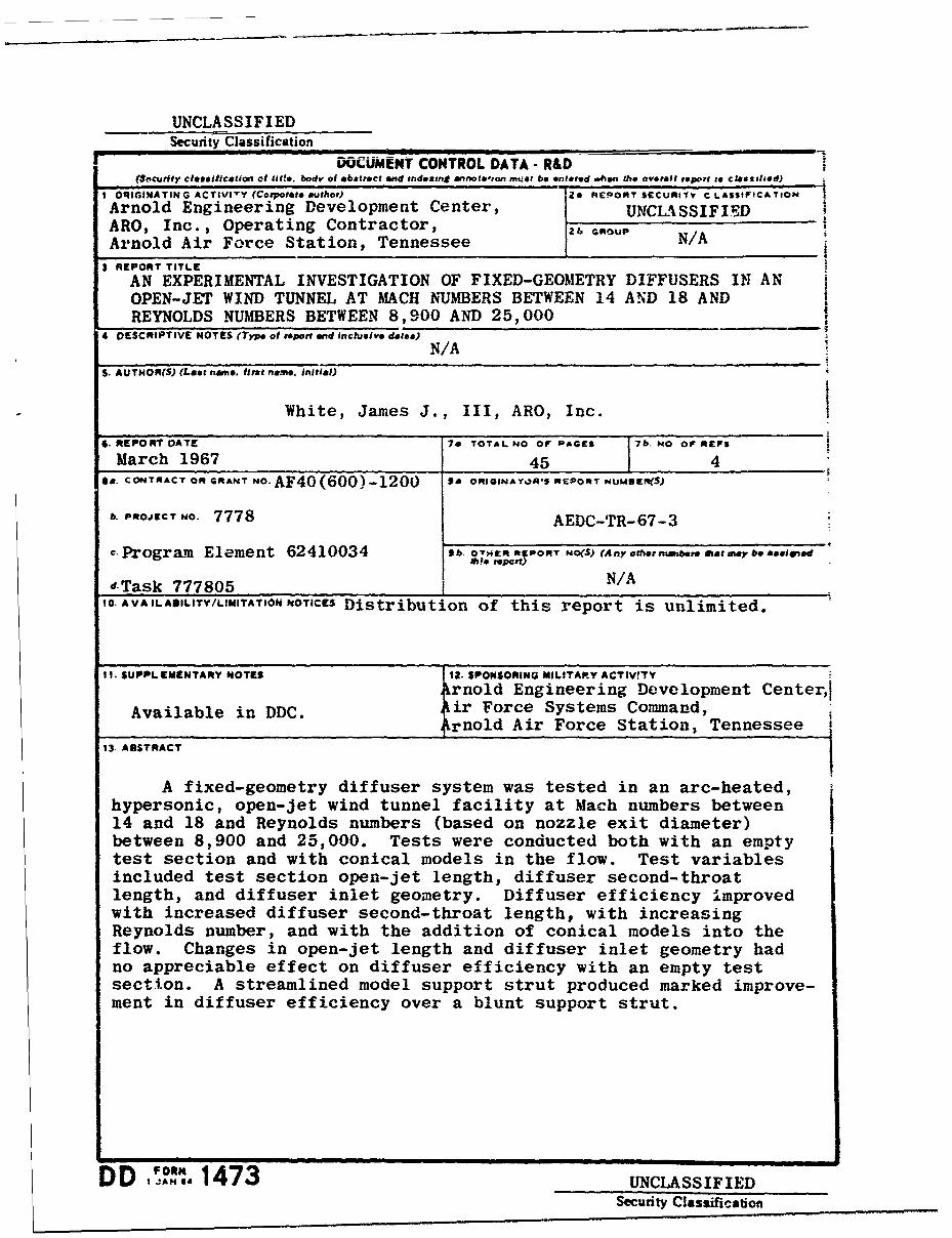
ABSTRACT
A fixed-geometry diffuser system was tested in an arc-heated,hypersonic, open-jet wind tunnel. facility at Mach numbers between 14and 18 and Reynolds numbers (based on nozzle exit diameter) between8,900 and 25,000. Tests were conducted both with an empty test sec-tion and with conical models in the flow. Test variables included testsection open-jet length, diffuser second-throat length, and diffuser inletgeometry. Diffuser efficiency improved with increased diffuser second-throat length, with increasing Reynolds number, and with the additionof conical models into the flow. Changes in open-jet length and diffuserinlet geometry had no appreciable effect on diffuser efficiency with anempty test section. A streamlined model support strut produced markedimprovement in diffuser efficiency over a blunt support strut. I
iii
AEDC-TR-67-3
CONTENTS
Page
ABSTRACT . .. .. .. .. .. .. .. .. .. .. . ii
NOMENCLATURE . . . . . . . . . . . . . . . . .. viI. INTRODUCTION . . . . . . . . . . . . . . . . . . 1
II. APPARATUS2.1 General Description . . . . . . . . 12 2 Blockage Models. . . . . . . . . . . . . . . 32. 3 Impact Pressure Probes . .. .. .. .. ..... 32o.4 Instrumentation .. .. .. .. .. .. .. . .. 3
III. EXPERIMENTAL PROCEDURE
3.1 Tunnel Operation. . . . . . . . . . . . . . .. 43.2 Data Reduction. . . . . . . . . . . . . . . . . 5
IV. RESULTS AND DISCUSSION4. 1 Empty Test Section .... . . . . . . . . . . 7
V. CONCLUSIONS ....... ................... . 10
REFERENCES . . . . . . . . . . ......... .. . 11
TABLE
1. Experimental Data on Diffuser Inlet Performance . .. . . 9
APPENDIXES
I. ILLUSTRATIONS
Figure
1. The 18-in. Hypersonic Wind Tunnel. . . . . . . . . 15
2. Sketch of the 18-in. Hypersonic Wind Tunnel. . . . . 16
3. Arrangement of Components in the Test Chamber. . . 17
4. Diffuser Inlet Geometries .............. 18
5. Diffuser Inlets .................. 19
6. Diffuser Exterior. . . . . . . . . . . . . . . 20
7. Diffuser Dimensions ................ 21
8. Blockage Models . . . . . . . . . . . . . . . . . 22
9. Streamlined Model Support . . . . . . . . . . . 23
V
Figure Page
10. Blunt Model Support .... ................ . 24
11. Test Section Impact Pressure Probe . . . . . . . . 25
12. Instrumentation Locations for Test Chamberand Diffuser . . . . . . . . . . . . . . . . . . . 26
13. Variation of Test Chamber Pressure with Diffuser
Exit Pressure - Empty Test Section . . . . . . . . 27
14. Test Section Flow Conditions. . . . . . . . . . . . 28
15. Effect of Open-Jet Length on Diffuser Efficiencywith Empty Test Section ... ...... .... . 29
16. Effect of Diffuser Length on Diffuser Efficiencywith Empty Test Section, Lj/DNE = 1. 5. .*. . . . . 30
17. Variation of Impact to Static Pressure Ratio atEnd of Diffuser Second Throat for Changes inSecond-Throat Length with Empty Test Section,Lj/DNE = 1. 5 . .. .. .. .. .. .. .. . .. 31
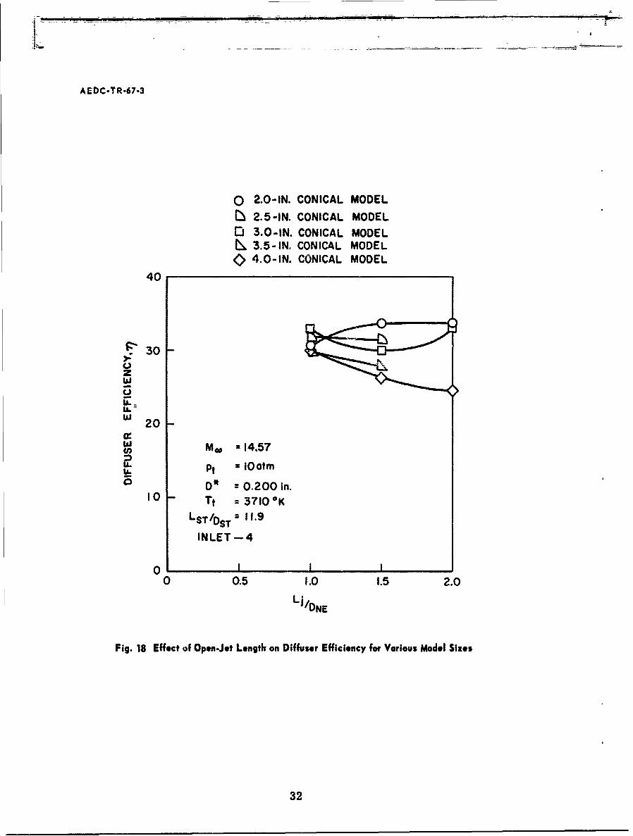
18. Effect of Open-Jet Length on Diffuser Efficiencyfor Various Model Sizes ............... 32
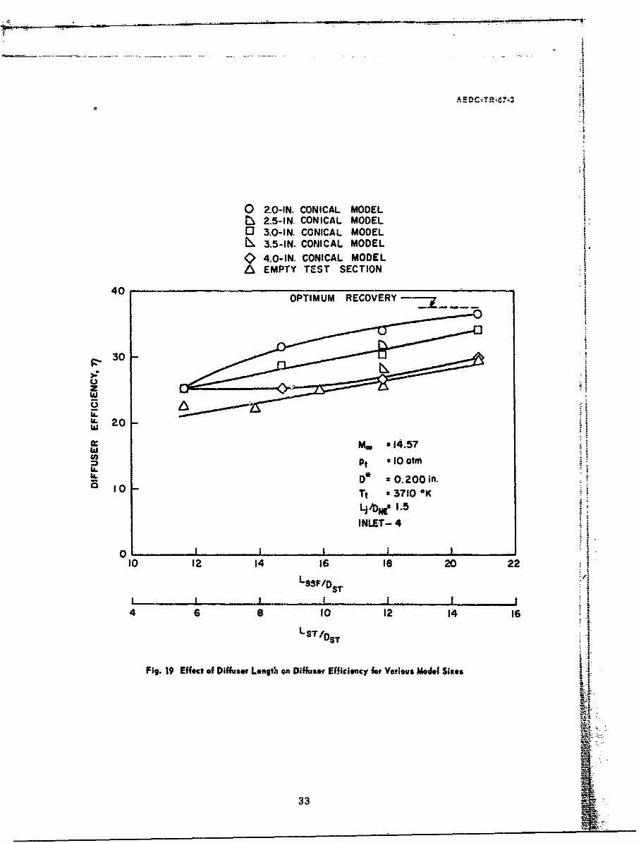
19. Effect of Diffuser Length on Diffuser Efficiencyfor Various Model Sizes ............... 33
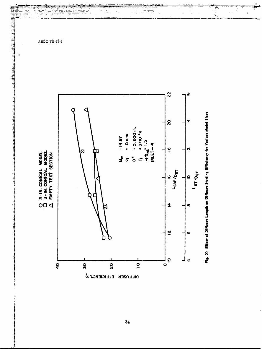
20. Effect of Diffuser Length on Diffuser StartingEfficiency for Various Model Sizes. . . . . . . . . 34
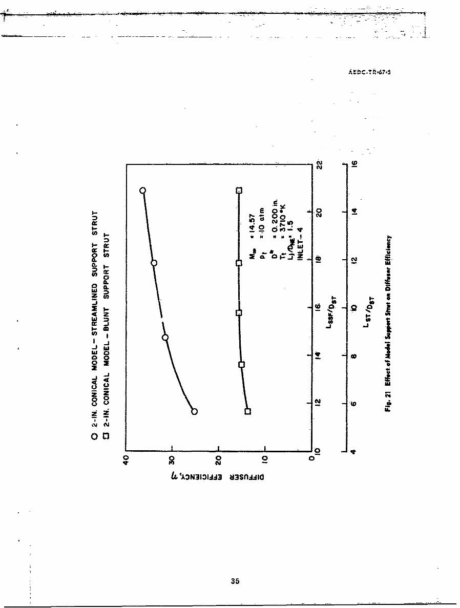
21. Effect of Model Support Strut on Diffuser Efficiency . 35
.1. DERIVATION OF THE EXPRESSION FOR THEOPTIMUM DIFFUSER RECOVERY PRESSURE. . . . . . 36
NOMENCLATURE
A Area
ANE Nozzle exit area
AST Diffuser second-throat area
D* Nozzle throat diameter
DNE Nozzle exit diameter
DST Diffuser second-throat diameter
vi
... .-- . . ...- V-f
AEDC-TR-67-3
Lj Open-jet length measured from nozzle exit planeto diffuser inlet plane
LSSF Supersonic flow length measured from throat station ofthe nozzle to the end of the diffuser second-throatsection
LST Diffuser second-throat length
M40 Free-stream Mach number on the flow centerline
rm Mass flow
Pc Test chamber pressure
Pd Diffuser exit wall static pressure
PST Static pressure at end of diffuser second throat
Pt Stilling chamber pressurePt" Test section impact pressure
d Diffuser downstream impact pressure on the flowcenterline
Pt, ST Impact pressure at end of diffuser second throat onthe flow centerline
Pt, to Test section impact pressure on the flow centerline
ReD Test section Reynolds number, P* U0 DNE
Tt Stilling chamber temperature
U Velocity
U40 Free-stream velocity on the flow centerline
a Momentum flux ratio at nozzle exit
Mass flux ratio at nozzle exit
Diffuser efficiency, Pd x 100
pa Viscosity of the free-stream flow on the flow centerline
p Density
pa Free-stream density on the flow centerline
vii
AEDC-TR-67-3
SECTION IINTRODUCTION
One of the main problems in designing a low density, hypervelocitywind tunnel is the selection of a pumping system to handle the mass flowsrequired at the very low pressures. Any available energy which can berecovered in the form of pressure will lessen the cost of a pumping sys-tem or, in an intermittent-type tunnel, increase the run time. The dif-fuser recovery pressure in a fixed-geometry diffuser system decreaseswith decreasing Reynolds number (Refs. 1 and 2). The present studywas conducted as a part of the continuing wind tunnel research effort atAEDC to establish diffuser design information on low density testingfacilities.
Tests were conducted in an arc-heated, open-jet wind tunnel facilitywith a fixed-geometry diffuser system. The tests were performed bothwith and without blockage models at Mach numbers between approximately14 and 18 and at Reynolds numbers (based on nozzle-exit diameter) between8, 900 and 25, 000. The test variables included diffuser second-throat length,open-jet length, diffuser inlet geometry, nozzle throat diameter (area ratio),and stilling chamber stagnation conditions.
SECTION 11APPARATUS
2.1 GENERAL DESCRIPTION
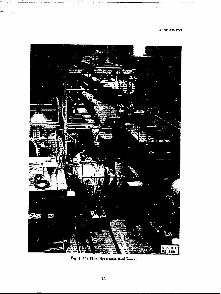
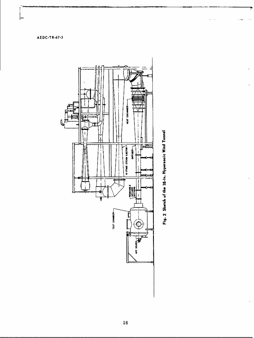
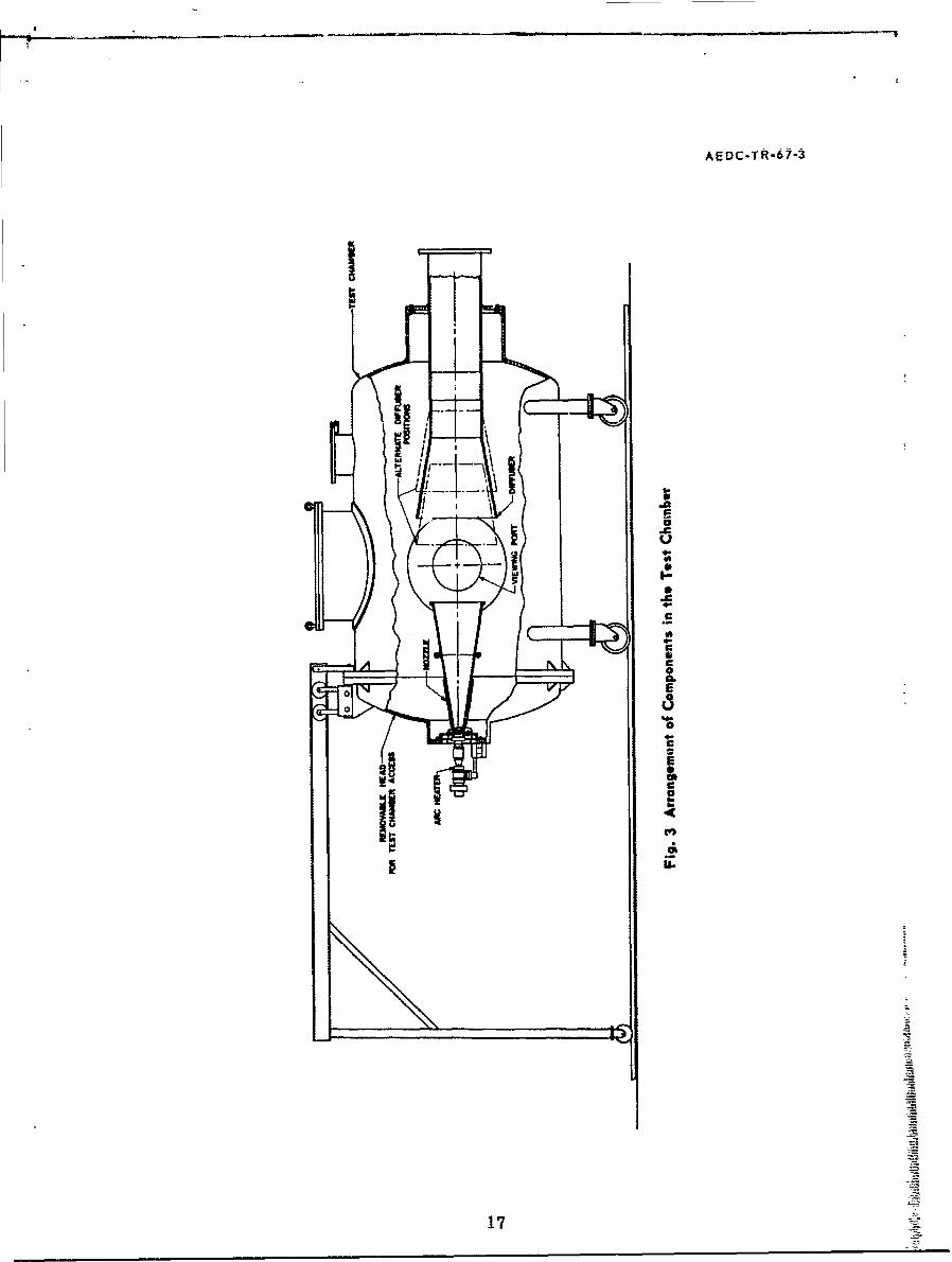
The experimental data were obtained in an 18-in. hypervelocity, lowdensity, open-jet wind tunnel. The tunnel is powered by a 250-kw d-celectric arc heater which is operated with air as a test fluid. The heatedair exhausts into a stilling chamber and is thence expanded through a noz-zle into an open-jet test section. The test gas is collected and deceleratedin a diffuser and exhausted by means of a six-stage steam ejector. Aphotograph of the facility is shown in Fig. 1 (Appendix I), and a schematicof the major components is exhibited in Fig. 2. A cutaway view of thetest chamber showing the nozzle and initial portion of the diffuser is givenin Fig. 3.
The arc heater consists of two water-cooled, electrically isolated,coaxial electrodes separated by a cylindrical vortex tube. The rearelectrode acts as the anode, and the front electrode serves as the cathodeand is the exit for the hot test gas. An auxiliary magnetic field coil serves
1
AEDC.TR-67-3
to rotate the arc in the anode to lessen electrode erosion and permitmore uniform heating of the gas. Air inlet ports in the cylindricalvortex tube can be adjusted to vary the airflow pattern within the arcchamber.
The stilling chamber is the connecting link between the arc heaterand nozzle. The chamber is 1. 50 in. in diameter by 3. 25 in. long andserves to improve the uniformity of the low in the test section. Thestilling chamber is water cooled.
The expansion section consists of a 10-deg half-angle conical nozzlewhich is water cooled over approximately half its length. Replaceablethroat sections permit varying the throat diameter. The nozzle exitdiameter is 18 in., and the minimum diameters of the two throat sectionsused in this test were 0. 137 and 0. 200 in.
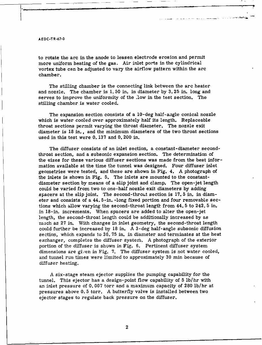
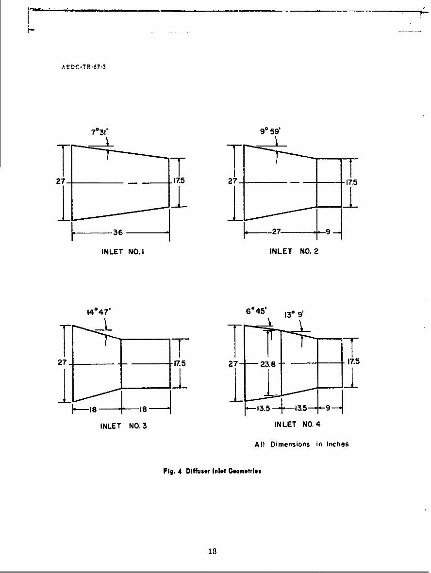
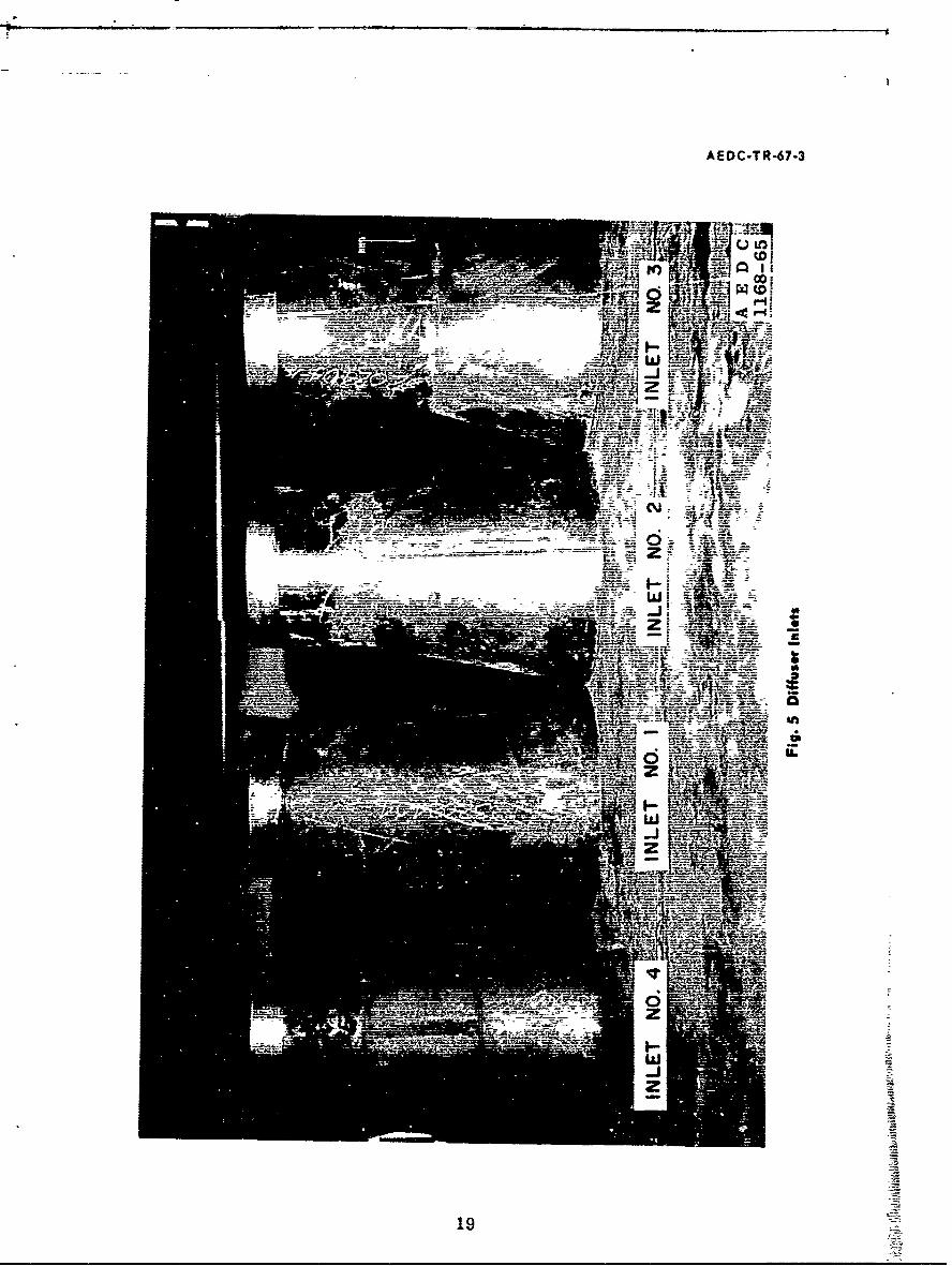
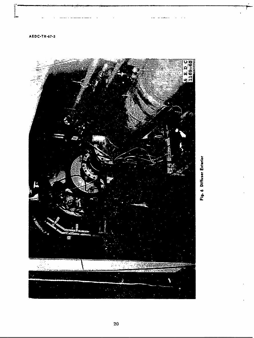
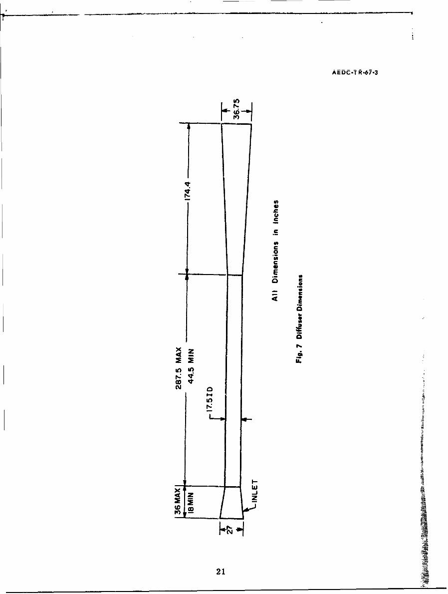
The diffuser consists of an inlet section, a constant-diameter second-throat section, and a subsonic expansion section. The determination ofthe sizes for these various diffuser sections was made from the best infor-mation available at the time the tunnel was designed. Four diffuser inletgeometries were tested, and these are shown in Fig. 4. A photograph ofthe inlets is shown in Fig. 5. The inlets are mounted to the constant-diameter section by means of a slip joint and clamp. The open-jet lengthcould be varied from two to one-half nozzle exit diameters by addingspacers at the slip joint. The second-throat section is 17. 5 in. in diam-eter and consists of a 44. 5-in. -long fixed portion and four removable sec-tions which allow varying the second-throat length from 44. 5 to 242. 5 in.in 18-in, increments. When spacers are added to alter the open-jetlength, the second-throat length could be additionally increased by asmuch as 27 in. With changes in inlet geometry, the second-throat lengthcould further be increased by 18 in. A 3-deg half-angle subsonic diffusionsection, which expands to 36. 75 in. in diameter and terminates at the heatexchanger, completes the diffuser system. A photograph of the exteriorportion of the diffuser is shown in Fig. 6. Pertinent diffuser systemdimensions are given in Fig. 7. The diffuser system is not water cooled,and tunnel run times were limited to approximately 30 min because ofdiffuser heating.
A six-stage steam ejector supplies the pumping capability for thetunnel. This ejector has a design-point flow capability of 5 lb/hr withan inlet pressure of 0. 007 torr and a maximum capacity of 280 lb/hr atpressures above 0. 5 torr. A butterfly valve is installed between twoejector stages to regulate back pressure on the diffuser.
2
AEDC-TR-67-3
2.2 BLOCKAGE MODELS
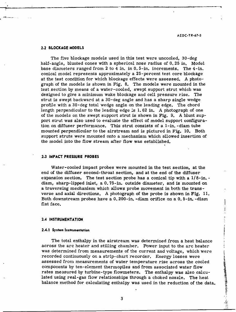
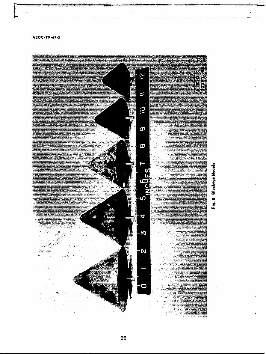
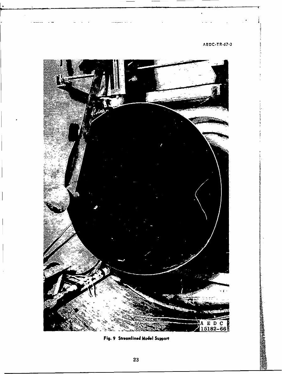
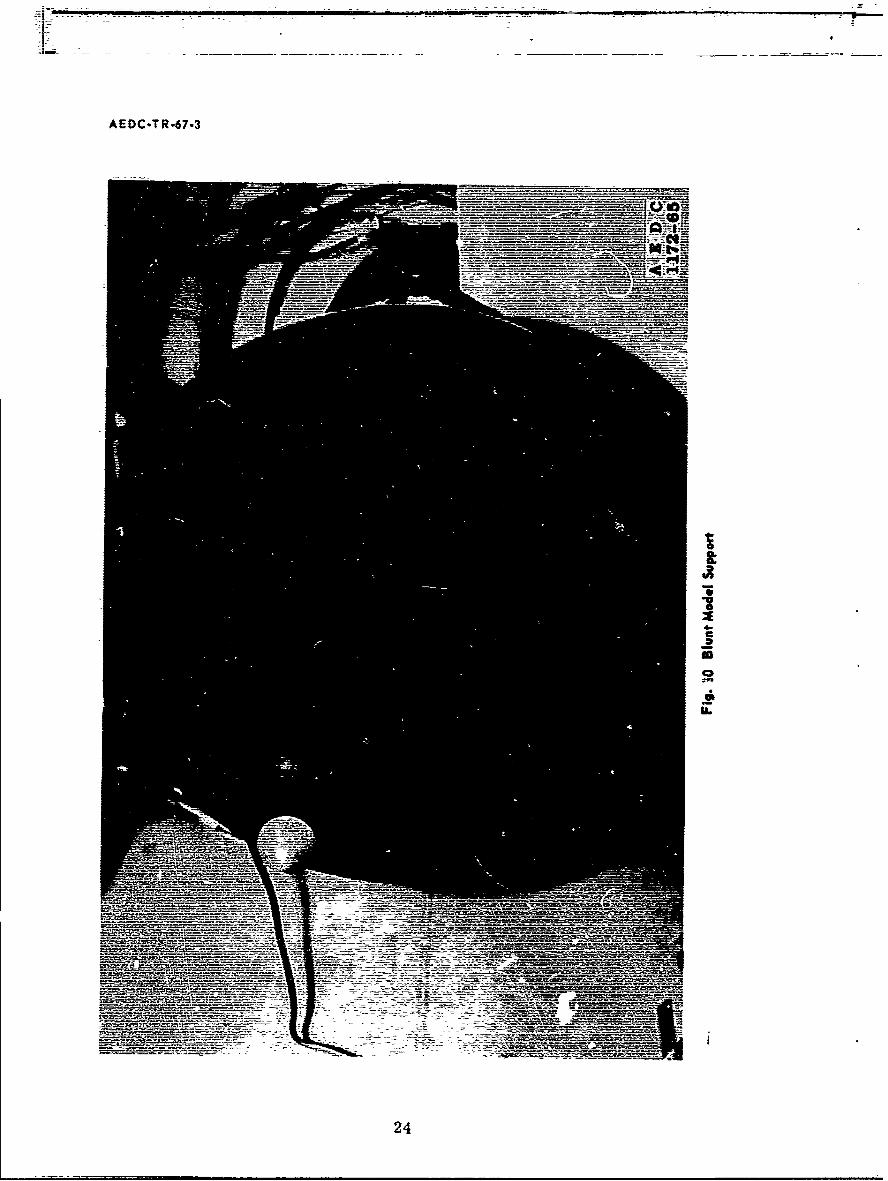
The five blockage models used in this test were uncooled, 30-deghalf-angle, blunted cones with a spherical nose radius of 0. 25 in. Modelbase diameters ranged from 2 to 4 in. in 0. 5-in. increments. The 4-in.conical model represents approximately a 25-percent test core blockageat the test condition for which blockage effects were assessed. A photo-graph of the models is shown in Fig. 8. The models were mounted in thetest section by means of a water-cooled, swept support strut which wasdesigned to give a minimum wake blockage and cell pressure rise. Thestrut is swept backward at a 30-deg angle and has a sharp single wedgeprofile with a 30-deg total wedge angle on the leading edge. The chordlength perpendicular to the leading edge is 1. 62 in. A photograph of oneof the models on the swept support strut is shown in Fig. 9. A blunt sup-port strut was also used to evaluate the effect of model support configura-tion on diffuser performance. This strut consists of a 1-in. -diam tubemounted perpendicular to the airstream and is pictured in Fig. 10. Bothsupport struts were mounted onto a mechanism which allowed insertion ofthe model into the flow stream after flow was established.
2.3 IMPACT PRESSURE PROBES
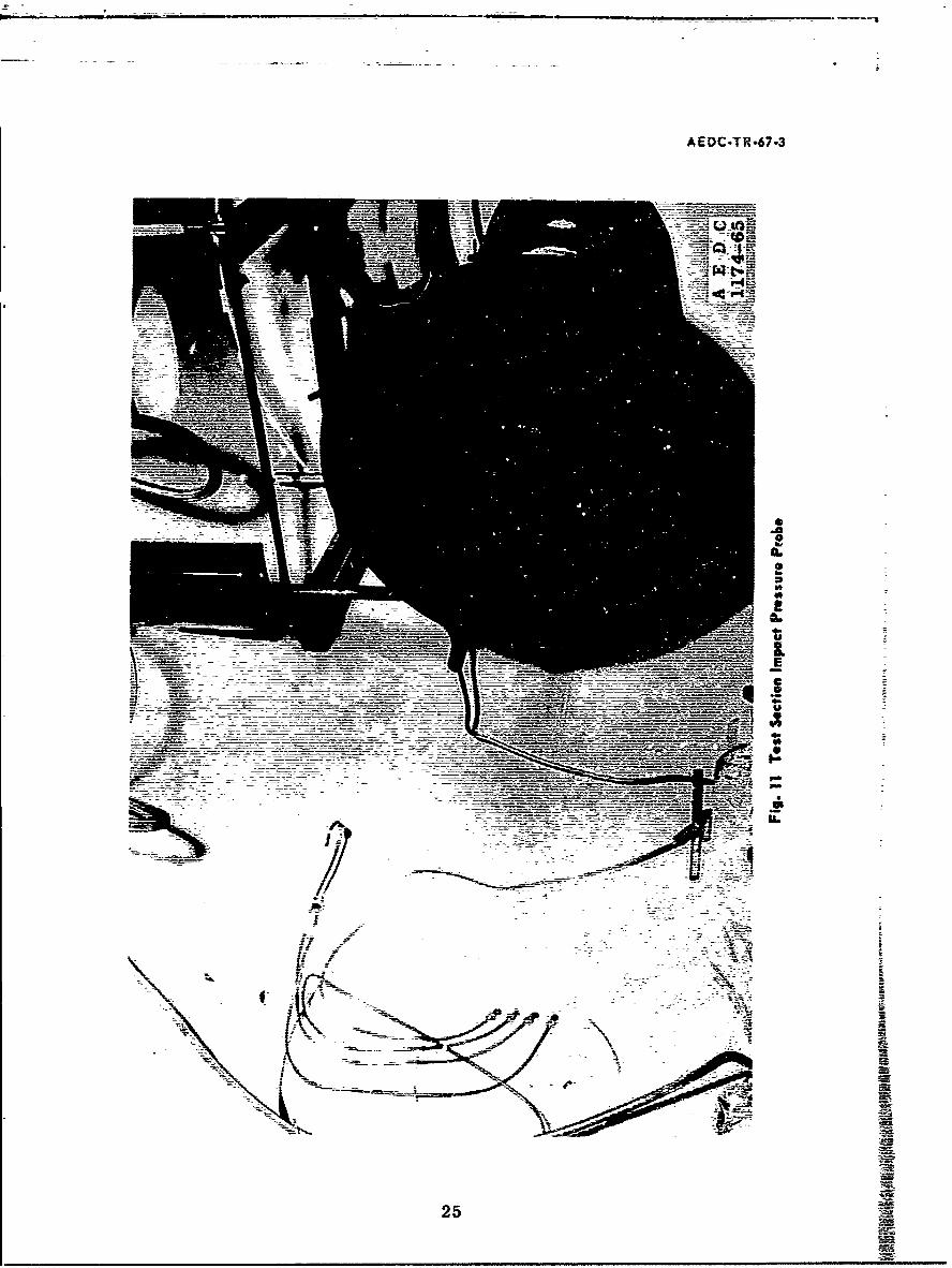
Water-cooled impact probes were mounted in the test section, at theend of the diffuser second-throat section, and at the end of the diffuserexpansion section. The test section probe has a conical tip with a 1/8-in. -diam, sharp-lipped inlet, a 0. 75-in. outside diameter, and is mounted ona traversing mechanism which allows probe movement in both the trans-verse and axial directions. A photograph of the probe is shown in Fig. 11.Both downstream probes have a 0. 200-in. -diam orifice on a 0. 5-in. -diamfiat face.
2.4 INSTRUMENTATION
2.4.1 System Instrumentation
The total enthalpy in the airstream was determined from a heat balanceacross the arc heater and stilling chamber. Power input to the arc heaterwas determined from measurements of the current and voltage, which wererecorded continuously on a strip-chart recorder. Energy losses wereassessed from measurements of water temperature rise across the cooledcomponents by ten-element thermopiles and from associated water flowrates measured by turbine-type flowmeters. The enthalpy was also calcu-lated using real-gas flow relationships through a choked nozzle. The heatbalance method for calculating enthalpy was used in the reduction of the data.
3
AEDC-TR-67-3
However, the differences in the two calculations were included in theevaluation of data precision as quoted in Section 2.4.2.
A sharp-edged orifice was used in the high pressure air supply lineto determine the mass flow rate. The pressure upstream of the orificeand the differential pressure across the orifice were measured withdiaphragm-type, strain-gage pressure transducers. An associated airtemperature measurement was made with an unshielded thermocouple.The stagnation pressure in the stilling chamber was also measured witha diaphragm-type, strain-gage pressure transducer.
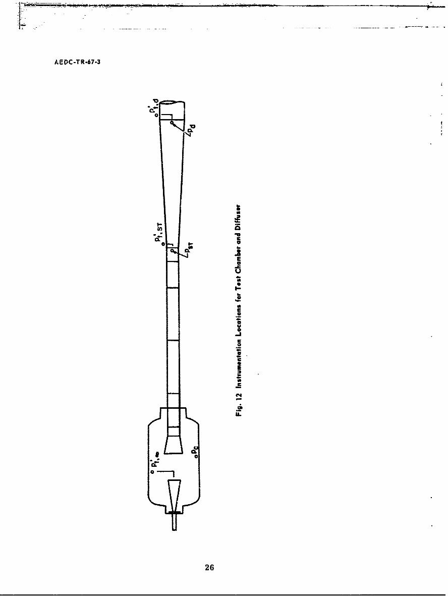
Impact and static pressures were measured in the test chamber andalong the diffuser. These pressures were measured with diaphragm-type,variable-capacitance pressure transducers designed to give good accuracyand installed to give rapid response at low absolute pressures. Locationsof pressure measurements in the test chamber and diffuser are shown inFig. 12.
2.4.2 Precision of Measurements
Calibrations were made periodically during this investigation on allinstrumentation components and their associated recorders. The repeat-ability of all instrumentation components from one calibration to the nextwas excellent; however, any small deviations were taken into account inreducing the data.
The precision of measurement of the data presented in this report isgiven below:
77 Pt Pc Pd Tt±1 ±0. 35 atm ±5 x 10 - 4 torr ±2. 0 x 10 - 2 torr ±3000 K
These estimates were calculated by a statistical analysis method describedin Ref. 3. All factors known to influence the measurements, and whichcould be assessed, are included in the calculations. The precisions quotedcorrespond to a confidence level of 95 percent.
SECTION IIIEXPERIMENTAL PROCEDURE
3.1 TUNNEL OPERATION
The following procedure was used to obtain diffuser recovery data.The instrumentation and arc heater were checked out before tunnel
4
AEDC-TR-67-3
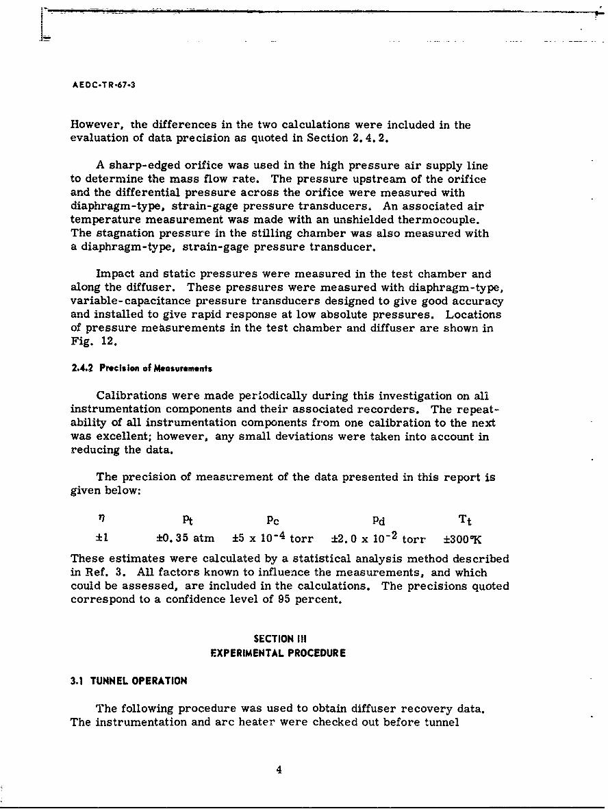
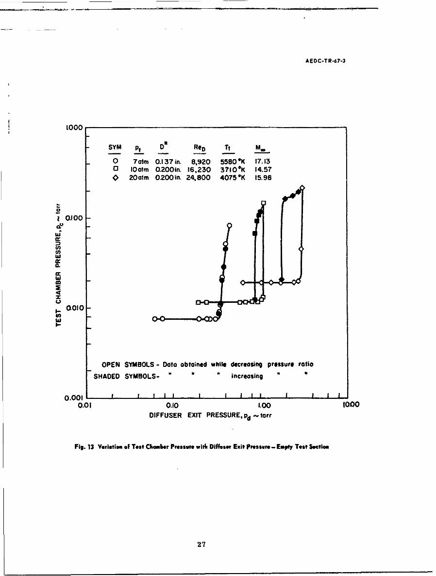
pumpdown. The entire tunnel was evacuated to a pressure from 0.01 to0.02 torr. Reference zeroes were then taken on the pressure instru-mentation in the test chamber and diffuser. High pressure demineralizedwater flow was initiated to the cooled components, and the airflow ratewas adjusted for startup. The tunnel pressure ratio, Pt/Pd, was set toa value known to be in excess of the diffuser starting pressure ratio. Thearc heater was started, and the airflow rate was then adjusted to obtainthe desired stilling chamber pressure. If the run was made without amodel, a centerline impact pressure measurement was taken 0. 25 in.downstream of the nozzle exit plane, and then the impact probe was re-moved from the flow. If a model was to be tested, it was introducedinto the flow on the tunnel centerline with the nose 0. 25 in. downstreamof the nozzle exit plane. (When testing with models, a centerline impactpressure was approximated by choosing an impact pressure from a tunnel-empty run for which the stagnation conditions closely approximated thosefor the individual model test run.) The tunnel pressure ratio was thendecreased in small increments by closing the diffuser butterfly valveuntil the test chamber pressure began to change with changes in diffuserexit pressure. The process was continued until the test chamber pres-sure was approximately an order of magnitude higher than the originalvalue. The tunnel pressure ratio was then increased in small incrementsuntil the diffuser flow was again started. A second impact pressure read-ing was then taken. At the end of a run, reference zeroes were taken onall recording instrumentation.
A sample of the data taken by the preceding method is given in Fig. 13.The three sets of data presented correspond to different nozzle area ratiosand stilling chamber pressures and were taken at a tunnel-empty condition.
3.2 DATA REDUCTION
3.2.1 Test Section Flow Properties
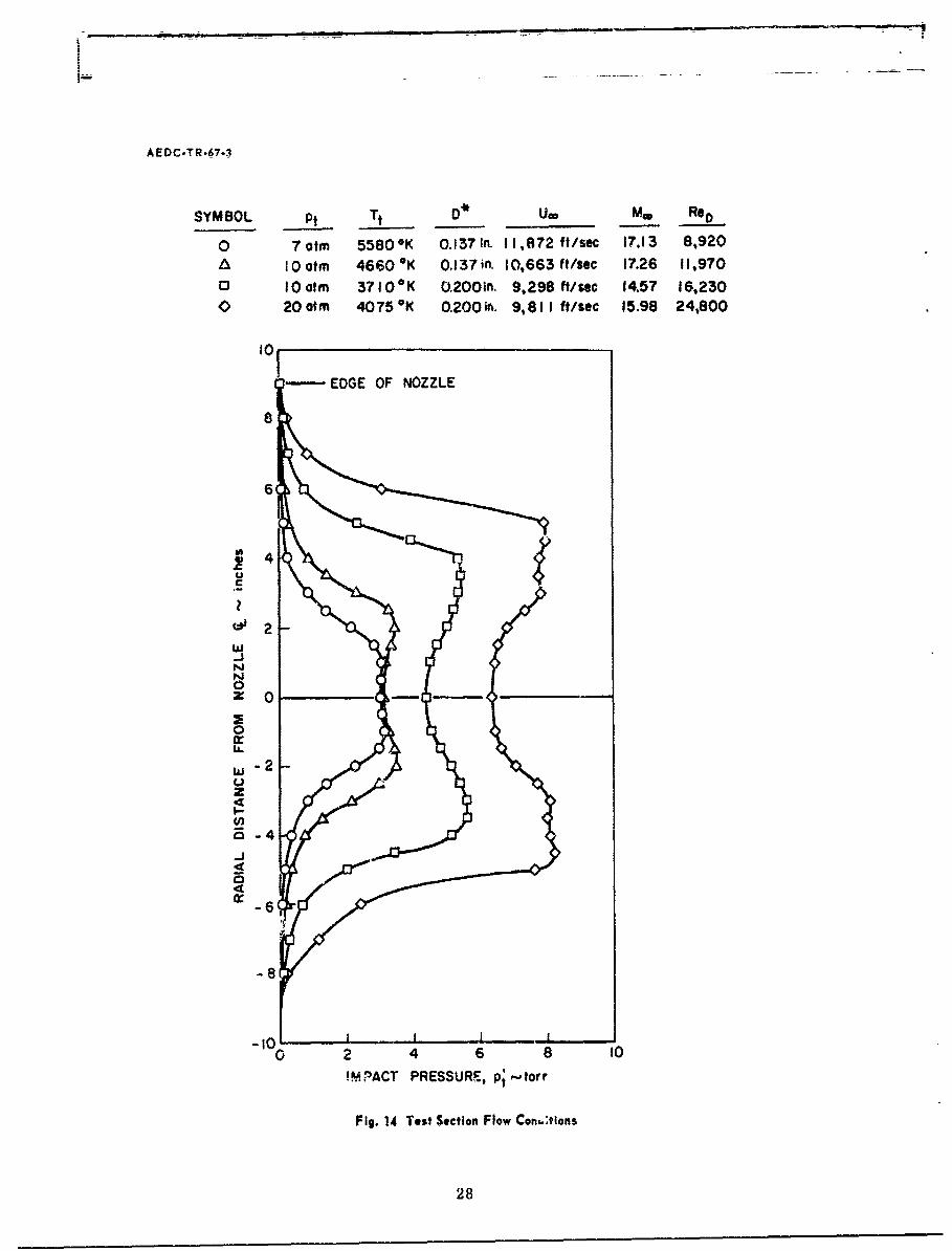
The test section flow properties listed in Fig. 14 were calculated byassuming equilibrium flow from the stilling chamber to the nozzle throatand completely frozen (both vibrationally and chemically) flow from thethroat to the test section. The justification for using this particular flowmodel was based on comparisons of test section flow properties determinedby this flow model and by nonequilibrium flow calculations utilizing a high-speed digital computer (Ref. 4). Both chemical species concentrationsand bulk thermodynamic properties were compared, and the differenceswere found to be small. With the flow model specified, free-stream flowproperties were calculated as a function of Mach number through the
I
AEDC-TR-67-3
supersonic expansion portion of the nozzle. This calculation was con-tinued for increasing Mach number until the calculated value of impactpressure (Pt' 0 - pu 2 ) was equal to the measured value of impactpressure on the centerline of the test section.
The variation of flow properties across the test section flow streamis represented by the impact pressure profiles given in Fig. 14. Theseprofiles were taken at the nozzle-exit station.
3.2.2 Diffuser Efficiency
The diffuser efficiency used in presenting these results is
Diffuser Exit Static PressureNormal Shock Recovery Pressure on the Centerline 100
Since the boundary layer occupies a large portion of the flow field(boundary-layer thicknesses can be inferred from the impact pressureprofiles in Fig. 14), the impact pressure on the nozzle centerline doesnot represent the average momentum in the flow field, and thus efficien-cies of 100 percent would not be generally anticipated. However, sincethis form of expression for diffuser efficiency is widely used in present-ing high Mach number facility performance results, it has been usedherein to permit direct comparison with other data by the reader.
The normal shock recovery pressure on the nozzle centerline wasmeasured with a sharp-lipped probe located 0.25 in. downstream of thenozzle exit. An impact pressure and a static pressure were measuredat the diffuser exit. When the diffuser second throat was long, thediffuser exit static and impact pressures were nearly equal. With a shortsecond-throat length, the centerline impact pressure was much higherthan the static pressure. However, from partial impact pressure surveystaken across the diffuser exit, the static pressure and average impactpressure were still very nearly the same. Hence, the diffuser exit staticpressure was used to represent the recovery of the diffuser. Differencesbetween the static pressure and average impact pressure were includedin the overall level of precision quoted for diffuser efficiency.
An equation for predicting the optimum diffuser recovery pressurein a hypersonic tunnel is
Pd mU00A7T
This equation represents the recovery pressure attainable if all the avail-able momentum in the test section flow is converted into pressure. Thederivation of this equation is given in Appendix I. Since the mass flow
6
AEDC-TR-67-3
rate and free-stream velocity are specified by the stilling chamber pres-sure, the air total enthalpy, and the nozzle throat diameter, the only wayindicated to improve the diffuser recovery is to reduce the second-throatarea. This assumes that the diffuser is sufficiently long to allow themomentum conversion process to be completed (see assumption (2),Appendix II). The required lengths must be determined experimentally.Other experimenters (e. g., Ref. 2) have shown this dependence of diffuserrecovery on second-throat area. For the present tests, a diffuser areaapproximately equal to the nozzle-exit area was selected as a compromisebetween the desire for high recovery and the need to operate with relativelylarge and blunt models. The results presented in Section 4.2 would seemto substantiate this choice as a reasonable one.
SECTION IVRESULTS AND DISCUSSION
Diffuser efficiencies are presented for tunnel operation with an emptytest section and also with conical models present in the flow. Unlessotherwise stated, the diffuser pressure used for defining the efficiencyis obtained during the diffuser flow breakdown process (decreasing pres-sure ratio). Referring to Fig. 13, the diffuser pressure at flow break-down is defined as the pressure which exists at the diffuser exit stationwhen the test chamber pressure has risen 10 percent above its originalvalue. The diffuser pressure used for defining the starting efficiency,which is given in several figures, is obtained while increasing the pres-sure ratio (see Fig. 13). The diffuser pressure when the flow has re-started is defined as the pressure which exists when the test chamberpressure is within 10 percent of its minimum value. Test variables in-clude stagnation conditions, nozzle throat diameter, diffuser inlet geom-etry, test section open-jet length, and diffuser second-throat length. Theeffects of a streamlined and a blunt model support strut on diffuser effi-ciency are also compared.
4.1 EMPTY TEST SECTION
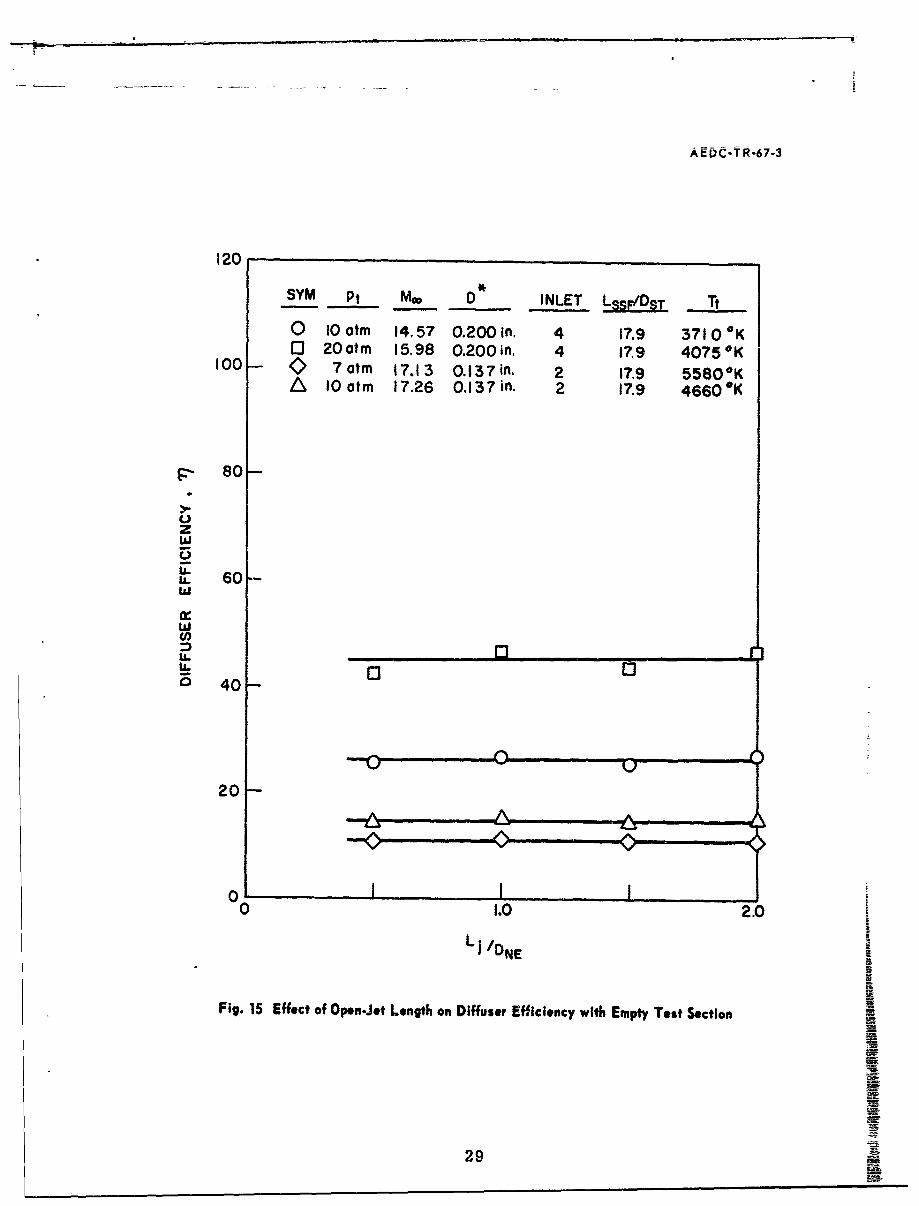
The effect of varying the test section open-jet length is given inFig. 15 for four different flow conditions and two diffuser inlets. Thesedata indicate that changes in open-jet length have no appreciable effect ondiffuser recovery for the range of conditions covered. I should be notedthat changes in open-jet length were produced by changing spacers to thesecond-throat duct and thus altered the length of the second throat (in-creasing LJ/DNE resulted in a corresponding decrease in LST) but did notchange the-overall supersonic flow length (LSSF).
7
AEDC-TR-67-3
Figure 16 demonstrates the effect of diffuser second-throat lengthon diffuser efficiency. It can be seen that diffuser efficiency increaseswith increased second-throat length and also increases with higherReynolds number. Also shown in Fig. 16 is the calculated value of theoptimum diffuser recovery obtained from the equations given in Section3.2.2. By linear extrapolation of the diffuser efficiency curves to theoptimum recovery, it can be observed that the diffuser second-throatlength required to achieve optimum recovery would need to be greaterfor lower Reynolds numbers, provided near-optimum recovery can beobtained at all conditions.
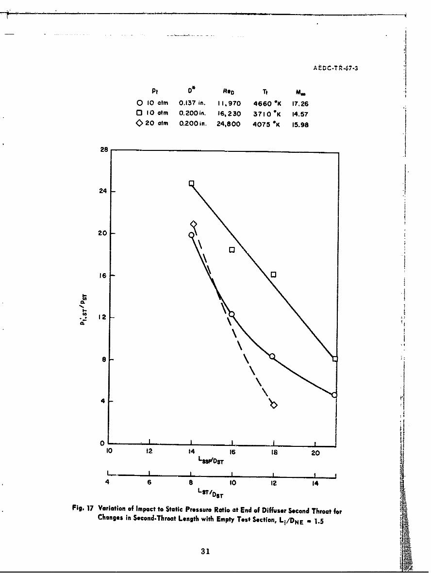
Impact and static pressures were obtained at the end of the diffusersecond throat. Referring to Fig. 17, it can be seen that the ratio ofimpact to static pressure, Pt* ST/PST , decreases with increasing second-throat length. Ideally, sonic'flow would exist at the end of the secondthroat, and the pressure ratio would be approximately two. It appearsthat this condition could be achieved with an increased second-throatlength, which has also been shown in the previous paragraph to be anecessary condition for achieving the optimum recovery.
The effect of diffuser inlet geometry on diffuser recovery was evalu-ated by testing the four diffuser inlets shown in Fig. 4. As can be seenin the following table, the diffuser efficiency was essentially the samefor all of the inlets.
Even though all four inlets in this investigation produced test pres-sures below the nozzle exit static pressure, inlet No. 3 (which had thesteepest inlet angle) produced slightly higher test chamber pressures atall conditions except the lower pressure with the smaller nozzle throat.This suggests that inlet angles less than 15 deg should be used to main-tain high diffuser pumping effectiveness, and thus low test chamberpressures.
The starting characteristic of the diffuser after flow breakdown isshown in Fig. 13. At the low Reynolds numbers, the starting and break-down pressure ratios are identical. However, it can be seen that as theReynolds number increases, a hysteresis effect occurs, and the startingpressure ratio is greater than the breakdown pressure ratio.
4.2 MODEL BLOCKAGE
The effects of model blockage on diffuser performance were deter-mined for one set of stagnation conditions. The effects of alteringdiffuser inlet geometry were not assessed.
8
AEDC-TR-67-3
TABLE I
EXPERIMENTAL DATA ON DIFFUSER INLET PERFORMANCE
NO. P otm D*, in. P.. tort 77 Lj/DNE
I 10 0.200 0.0126 21.7 1.5
2 0.0125 26.1
3 0.0142 26.3
4 . 0.0115 26.1
I 20 0.200 0.0193 48.1 1.5
2 0.0175 46.6
3 0.0250 46.14 i t0.0190 44.4 1
I 7 0.137 0.0070 11.7 1.5
2 0.0066 11.5
3 00073 10.7
4 0.0075 11.91 toI 0.137 0.0075 14.0 1.5
2 0.0075 14.6
3 0.0090 14.6
4 0.0063 15.0
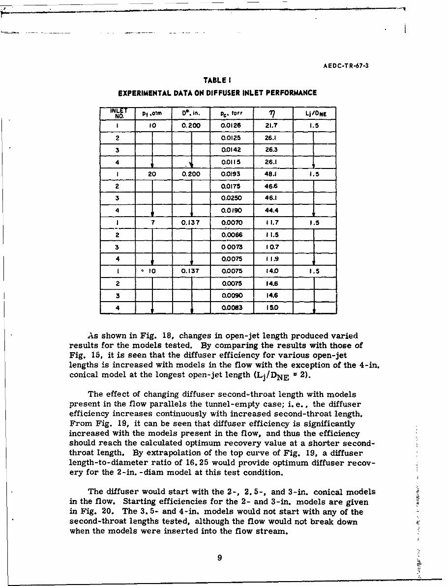
As shown in Fig. 18, changes in open-jet length produced variedresults for the models tested. By comparing the results with those ofFig. 15, it is seen that the diffuser efficiency for various open-jetlengths is increased with models in the flow with the exception of the 4-in.conical model at the longest open-jet length (Lj/DNE = 2).
The effect of changing diffuser second-throat length with modelspresent in the flow parallels the tunnel-empty case; i.e., the diffuserefficiency increases continuously with increased second-throat length.From Fig. 19, it can be seen that diffuser efficiency is significantlyincreased with the models present in the flow, and thus the efficiencyshould reach the calculated optimum recovery value at a shorter second-throat length. By extrapolation of the top curve of Fig. 19, a diffuserlength-to-diameter ratio of 16.25 would provide optimum diffuser recov-ery for the 2-in. -diam model at this test condition.
The diffuser would start with the 2-, 2. 5-, and 3-in. conical modelsin the flow. Starting efficiencies for the 2- and 3-in. models are givenin Fig. 20. The 3.5- and 4-in. models would not start with any of thesecond-throat lengths tested, although the flow would not break downwhen the models were inserted into the flow stream.
9
AEDC-TR-67-3
Figure 21 demonstrates the effect of the type of support strut usedto hold the model. The diffuser efficiency with the streamlined supportstrut (Fig. 9) is more than double that for the blunt strut (Fig. 10) exceptfor the shortest second-throat length. The increased efficiency with thestreamlined strut is probably caused by a decreased wake blockage anda more efficient oblique shock system generated in the diffuser.
SECTION VCONCLUSIONS
As a result of this experimental investigation, the following con-clusions can be reached:
1. Changes in open-jet length for Li/DNE from 0. 5 to 2 didnot alter the diffuser efficiency &ar tests without models.
2. Diffuser efficiency improved with increased second-throatlength both with and without models in the flow.
3. For the one set of stagnation conditions at which model datawere obtained, higher diffuser recoveries were obtainedwhen models were in the flow than for the tunnel-emptycase.
4. Changing d:iLuser inlet geometry had an insignificanteffect on diffuser recovery for tests with the tunnel empty.
5. Diffuser efficiency increased with increasing Reynoldsnumbers.
6. For optimum diffuser recovery, the indicated diffusersecond-throat length increases with decreasing Reynoldsnumbers.
7. Using a streamlined model support strut resulted in diffuserefficiencies more than double those obtained using a bluntmodel support strut.
10
AEDC-TR-67-3
REFERENCES
1. Boylan, David E. "An Experimental Study of Diffusers in anOpen-Jet, Low-Density, Hypersonic Wind Tunnel.AEDC-TDR-64-47 (AD434380), April 1964.
2. Clark, Lewis E. "Description and Initial Calibration of theLangley 12-Inch Hypersonic Ceramic-Heated Tunnel."NASA TN D-2703, March 1965.
3. Dean, Robert C., Jr. Aerodynamic Measurements. GasTurbine Laboratory, Massachusetts Institute of Technology,Eagle Enterprises, Boston, 1953.
4. Marshall, John C., ARO, Inc. Private Communication. 1966.
11
APPENDIXES
I. ILLUSTRATIONSlI. DERIVATION OF THE EXPRESSION FOR THE
OPTIMUM DIFFUSER RECOVERY PRESSURE
13
AEDC-TR-67-3
Fig. 1 Th. 18.in. Hyporsonic Wind Tunnel
15
AEDC-TR-67-3
I C
C
166
A ED C -T k-67-3
Uu
IS0
171
7031 90 596
71TI I27- 17.5 27 --- 17.5
INLET NO.1I INLET NO. 294
1447' 60456 3*9
278 1 .5 13.5.
INLET N.3INLET NO. 4
All Dimensions in Inches
Fig. 4 Diffuser Inlet Geometries
18
AEDC-TR-67-3
Q LO
.~ '* I4
___ 4 7iv
ML
0 40
19
AEDC-TR-67-3
20
AEUC*TR-67-3
C
c
0
0E
1c
E
'5 Z
CDC
21%
t
AE DC-T R-67-3
~. @~,- ______
__ -~ ____
A
__ __ __ 0 ____ __
_ _ ___itt~r~r=~oa
0
____ ____ go _____
__-r
____ a
__ ____ ___ I_____ ___ I
_____ egO S____ ___ ___ a
_____ __ ___ p~- *M__________ U
_________ ___ a 0__ __ _ ~ I
__ __ S______ ___ ______ ___ -=~ 6.
a - -t~=
4.
22
AA
-- **- f
Fig. 9 Streamlined Model Support R
23
AEDC-TR-67-3
______ 7I1 o=
_____ - :i C
________4
AEOC-TR-67-3
u 0 tR
Ma
E
25-
rc
-j
0C
0c
le
00
I26
AEDC-TR-67-3
fLOOO
SYM Pt DRe 0 t
o 7at'n 0.137in. 89,920 5580 K 17.13o3 lOotm 0.2001n. 16,230 3710 K 14.57
0 2Oalm 0200in. 24,800 4075-K 15.98
U
0
Z
4 L1
OPEN SYMBOLS - Data obtained white decreasing pressure ratio
SHADED SYMBOLS- increasing
0.01 0.10 LOO 1000DIFFUSER EXIT PRESSURE, Pd ~torr
Fig. 13 Variation of Test Chambeir Pressure with Diffuser Exit Pressvre - Empt Test Socti..
27
AEOC.TR.67.1
SYMBOL pf T D use Ma ROD
0 7 atm 55800K 0.137 in. 11,872 ft/sec 17.13 8,920A 10 atm 4660 OK 0.137 in, 10,663 ft/sec 17.26 11,970
0 loatm 37 10 K 0.200in. 9,298 ft/sec 14.57 16,2300 20 atm 4075OK 0.200 in, 9,811 ft/sec 15.98 24,800
10
-EDGE OF NOZZLE
8
6
4
C
w
0
0U.
U
z4
i-69
-10
0 2 4 6 8 10'M'Acr PRESSURE, pi tor r
Fig. 14 Test Section Flow Con,.:tions
28
AEDC-TR-67-3
120
SYM Pt mooD INLET LSSF/D.....
o 10 Otm 14.57 0.200 in, 4 17.9 3710ONo 200tmn 15.98 0.200 in. 4 17.9 4075OK100 0 7 atm 17.13 0.137 in. 2 17.9 5580OK
A 10otm 17.2r. 0.137il. 2 17.9 46600K
F= 80-
zU
U. 60--
Ii.
2040 0
20-
0.
Lj 'ONE
Fig. 15 Effect of Open-Jet Length on Diffuser Efficiency with Empty Test Section
29

AEDC-TR-67-3
o0 0 REAKDOWN 0.137 itn.O3 RESTART D .3 n
R*Dz 11,970Tt z 4660"K
J0 Ma -17.2620 OPTIMUM RECOVERY
40
OPTIMUM RECOVERYI]-z
u.20
LU Re 0 Ibt
U. Tt z 37100K0. ;Mm =14.57 1
60
OPTI MUM RECOVERYI - - - --
40
20 - D* =0. 200 in.20ROD =24,800
Tt 40750KM = 15.98
0 - -I I10 12 14 16 18 20
I I I IS
4 6 8t1 12 14
LST /DST
Fig. 16 Effect of Diffuser Length on Diffuser Efficiency with F-pty Test Section,LI/DNE 1.5
30
S. %F rf -9 1
pt R e() Tt Mo 10 atm 0.137 in. 11,970 4660 *K 17.26o3 10 atm 0. 200 in, 16,230 3710 K 14.57
''20 atm 0.200 in. 24,800 4075 *K 15.98
28
24
20
0
16
S 12
8
4
0 -
10 12 14 16 Is 20LSWDST
4 6 8t1 12 14
Fig. 17 Variation of Impact to Static Pressure Ratio at End of Diffuser Second Throet for 4Changes In Second-Throat Length with Empty Test Section, LI/DNE -1.5 1M
31 M
AEDC-TR-67-3
o 2.0-IN. CONICAL MODEL
[ 2.5-IN. CONICAL MODELO 3.0-IN. CONICAL MODELt 3.5-IN. CONICAL MODEL< 4.0-IN. CONICAL MODEL
40
30
z
5L_U.=
w
M0 a 14.57)Pt a lo tm
U.
D t = 0.200 in.10 Tt = 3710 *K
LST/DST= 11.9
INLET-4
o I . I I0 0.5 1.0 1.5 2.0
Lj /DNE
Fig. 18 Effect of Open-Jet Length on Diffuser Efficiency for Various Model Sizes
32
ASD T47
o 2.0-IN. CONICAL MODELt~2.5-IN. CONICAL MODELO3.0-IN. CONICAL MODELt~3.5-IN. CONICAL MODEL
S4.0-IN. CONICAL MODELL~EMPTY TEST SECTION
40 OPTIMUM RECOVERY
30
20LU
Ii. 20145w
pt 10 otmD* 0. 200in.
10Tt 3710 *K
INLET- 4
10 12 14 16 is 20 22
4 6 8 10 12 14 16
LST 1 S
Fig. 19 Effect of Diffuser Length on Diffuser Efficienicy for Various Model Sizes
33
000
NN
# 0
00
.f .U 0
pI -- I
00(AO(f
zA - %
0 0
zz)N11A4 aan.i
34-
A am.
o--
I- -
0 '
CU'
0 0 042 I-fu
I-i3114 utn
35I
AEflf-TD-A7-3
APPENDIX IfDERIVATION OF THE EXPRESSION FOR THE OPTIMUM
DIFFUSER RECOVERY PRESSURE
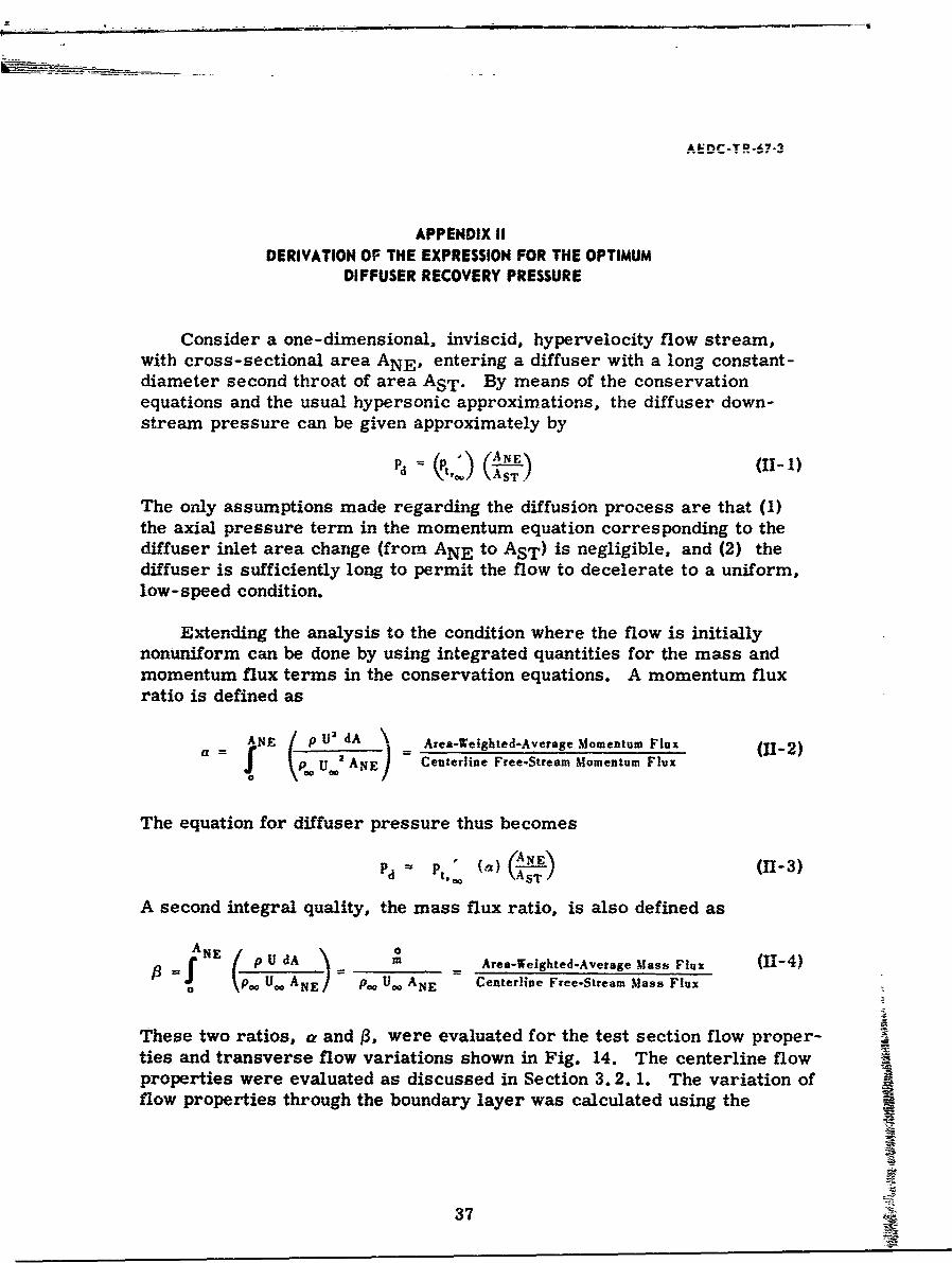
Consider a one-dimensional, inviscid, hypervelocity flow stream,with cross-sectional area ANE, entering a diffuser with a long constant-diameter second throat of area AST. By means of the conservationequations and the usual hypersonic approximations, the diffuser down-stream pressure can be given approximately by
Pd=() (A
The only assumptions made regarding the diffusion process are that (1)the axial pressure term in the momentum equation corresponding to thediffuser inlet area change (from ANE to AST) is negligible, and (2) thediffuser is sufficiently long to permit the flow to decelerate to a uniform,low-speed condition.
Extending the analysis to the condition where the flow is initiallynonuniform can be done by using integrated quantities for the mass andmomentum flux terms in the conservation equations. A momentum fluxratio is defined as
aN / U 2 dA Area-Weighted-Average Momentum Fluxa= \ Pe' UANE - Centerline Free-Stream Momentum Flux
The equation for diffuser pressure thus becomes
P - ( a ) "ANE- (H-3)
A second integral quality, the mass flux ratio, is also defined as
A NE a/ ( U dA m Area-Weighted-Average Mass Flux (H-4)
o pUo ANE, U ANE Centerline Free-Stream Mass Flux
These two ratios, a and 1, were evaluated for the test section flow proper-ties and transverse flow variations shown in Fig. 14. The centerline flowproperties were evaluated as discussed in Section 3.2. 1. The variation offlow properties through the boundary layer was calculated using the
37
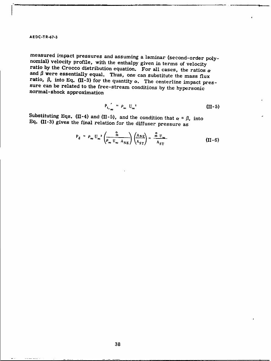
AEDC-TR-67-3
measured impact pressures and assuming a laminar (second-order poly-nomial) velocity profile, with the enthalpy given in terms of velocityratio by the Crocco distribution equation. For all cases, the ratios aand 3 were essentially equal. Thus, one can substitute the mass fluxratio, /3, into Eq. (11-3) for the quantity a. The centerline impact pres-sure can be related to the free-stream conditions by the hypersonicnormal- shock approximation
p t. - P/ U 3' (II-5)00 0
Substituting Eqs. (11-4) and (11-5), and the condition that a 13, intoEq. (11-3) gives the final relation for the diffuser pressure as
Pdp. U.02 ( ~'AE ANE\= - U. (11-6)U.. ANE (A ST) AST
38
UNCLASS5IFI EDSecurity Classification______
r DOCUMENT CONTROL DATA - R&D(SecuvdtY Cl41#8fication of Ltilt. bodv of abstract end trideuang Ont'00181,on must be entered *Agn the avotatt repoe s cSlssifad)
IORIG~INATING ACTIVIvY (Corporate author) 20a AROT SECuRI TV C LASSIFICA TION
Arnold Engineering Development Center, UNCLISSIFIEDARO, Inc., Operating Contractor, N/AOUArnold Air Force Station, TennesseeN/
3 REPORT TITLE
AN EXPERIMENTAL INVESTIGATION OF FIXED-GEOMETRY DIFFUSERS IN ANOPEN-JET WIND TUNNEL AT MACH NUMBERS BETWEEN 14 AND 18 ANDREYNOLDS NUMBERS BETWEEN 8,900 AND 25,000
4 DESCRIPTIVE NOTES (Type of report and inclusive does)
N/AS. AUTHOR(S) (Lost narn. frst name. Initial)
White, James J., III, ARO, Inc.
6. REPORT DATE 0TTLN FPGIS 7.N rmr
March 1967 4So. CONTRACT OR GRANT NO. AF4O (600) -1200 9. ORICINArOR'S REPORT NUWIIER(S)
NO. 7778AEDC-TR-67-3
cProgram Element 62410034 ob. OHfIR a PORT NO($) (Any ether tufbere shot may be assiond
d.Task 777805 jN/A
10. A VAIL AILITY/LIMITATION NOTICE$ Distribution of this report is unlimited.
11. SUPPLEMENTARY NOTES 12. SPONSORING MILITARY ACTIVITY
Avilbl DC r orce Systnemsn Command, tCeneAvilbl n DC ode Enginein DCvlometandr~
irnold Air Force Station, Tennessee13. ABSTRACT
A fixed-geometry diffuser system was tested in an arc-heated,hypersonic, open-jet wind tunnel facility at Mach numbers betweenbetwen 18,0 and 25,000.s Tumess wbaee onductze bot withanmempty14twan 18,0 and eynolds numes (base condnozzed exth ditate)ttest section and with conical models in the flow. Test variablesincluded test section open-jet length, diffuser second-throatlength, and diffuser inlet geometry. Diffuser efficiency improvedwith increased diffuser second-throat length, with increasingReynolds number, and with the addition of conical models into theflow. Changes in open-jet length and diffuser inlet geometry hadno appreciable effect on diffuser efficiency with an empty testsection. A streamlined model support strut produced marked improve-ment in diffuser efficiency over a blunt support strut.
D D !AON 4-1473 UNCLASSIFIEDSecurity Classification
.NCLA SS IF IED
Security Classification14 L . . .INK A LINK 13 LINK C
KEY WORDS ROLtE WT ROLE WT ROLE WT
diffuser systemsfixed geometry diffuserswind tunnel testingconical modelstunnel-empty testinghypersonic flow
INSTRUCTIONS
1. ORIGINATING ACTIVI"'.Y: Enter the name and address imposed by security classification, using standard statementsof the contractor, subcontractor, grantee, Department of De- such as:fense activity ot other organization (coqporr'e author) Issuing (1) "Qualified ' . ,esters may obtain copies of thisthe report. report from D-1 &"2a. REPORT SECURTY CLASSIFICATION: Enter the over- (2) "Foreign announcement and dissemination of thisall security classification oC the report. Indicate whether"Restricted Data" is included. Marking is to be in accord- report by DDC is not authorized."ance with appropriate security regulations. (3) "U. S. Government agencies may obtain copies of
this report directly from DDC. Other qualified DDC2b. GROUP: Automatic downgrading is specified in DoD Di-uershlrqettrog
rective 5200. 10 and Armed Forces Industrial Manual. Enter users shall request throughthe group number. Also, when applicable, show that optionalmarkings have been used for Group 3 and Group 4 as author- (4) "U. S. military agencies may obtain copies of thisized. report directly from DDC. Oth' qualified users
3. RE.ORT TITLE: Enter the complete report title in ail shall request throughcapital letters. Titles in all cases should be unclassified.If a meaningful title cannot be selected without claqsifica-tion, show title classification in all capitals in parenthesis (5) "All distribution of this report is controlled. Qual-immediately following the title. ified DDC users shall request through4. DESCRIPTIVE NOTES: If appropriate, enter the type of 'itreport, e.g., interim, progress, summary, annual, or final. If the report has been furnished to the Office of TechnicalGive the inclusive dates when a spe.ific reporting period is Services, Department of Commerce, for sale to the public, indi-covered, cate this fact and enter the price, if known.5. AUTHOR(S): Enter the name(s) of author(s) as shown on IL SUPPLEMENTARY NOTES: Use for additional explana-or in the report. Entei last name, first name, middle initial, tory notes.If military, show rank and branch of service. The name ofthe peincip il .- 'thor _, an absolute minimum requirement. 12. SPONSORING MILITARY ACTIVITY: Enter the name of
the departmental project offi:e or laboratory sponsoring (pay6. REPOR'i DAT- • Enter the date of the report as day, ing for) the research and development. Include address.month, y-ear; %,r month, year. If more than one date appearson the repo'rt, usc date of publication. 13 ABSTRACT. Enter An abstract giving a brief and factual
summary of the document indicative of the report, even though7a. TOTAL NUMBER OF PAGES: The total page count t nay also appear elsewhere in the body of the technical re-should follow normal pagination pr',cedures, i.e., enter the port. If additional space is required. a continuation sheet shallnumber of pages contining information, be attached.
7b. NUMBER OF REFERENCES Enter the total number of It is highly desirable that the abstract of classified reportsreferences cited In the report. be unclassified. Each paragraph of the abstract shall end with
e. CON" " ACT OR GRANT NUMBER: If appropriate, enter an Indication of the militLry security classification of the in-the applicaL.c number of the contratt or grant under which formation in the par.graph, represented as (TS), (S), (C), or (U).the repcrt was written. There is no limitation on the length of the abstract. How-Sb, 8c, & 8d. PROJECT NUMBER: Enter the approoriate ever, the suggested length is from 150 to 225 words.military department identification, sucn as project .,mber,subproject number, syste numbers, ask number, etc.14. KEY WORDS: Key words are technically meaningful termsor short phrases that characterize a report and may be used as9a. ORIGINATOR'S REPORT NUMBER(S): ELter the offi- index entries for cataloging the report. Key words must becial report number by which the document will be identified relected so that no security classification is required. Identi-and contrc..ed by the originating activity. This number must tihrs, such as equipment model designation, trade name, militarybe uniqu- t) this report. project code name, geographic location, may be used as key96. OTHER REPORT NUMbER(S, If the report has been wordp bit will be foliowed by an indication of technical con-assigned any other report numbers (either by the orilsnator text. The assignment of links, rules, and %eights is optional.or by the sponsor), also enter this numbers),10. AVAILABILITY/LIMITATION NOTICES: Enter any lim-itations on further dis--mination if the report, other than those
I______UNCLenSSXFIED