operating instructions vlt lift drive ld 302...1 introduction 1.1 purpose of the manual this manual...
TRANSCRIPT

MAKING MODERN LIVING POSSIBLE
Operating InstructionsVLT® Lift Drive LD 302
www.danfoss.com/drives


Contents
1 Introduction 4
1.1 Purpose of the Manual 4
1.2 Additional Resources 4
1.3 Document and Software Version 4
1.4 Intended Use 4
1.5 Certifications 4
1.6 Disposal Instruction 4
2 Safety 5
2.1 Qualified Personnel 5
2.2 Safety Precautions 5
3 Mechanical Installation 6
3.1 Equipment Pre-installation Check List 6
3.2 Unpacking 6
3.3 Installation Environment 6
3.3.1 Installation Site Check List 6
3.4 Mounting 6
3.4.1 Cooling 6
3.4.2 Lifting 7
3.4.3 Mounting 7
4 Electrical Installation 8
4.1 Safety instructions 8
4.1.1 Requirements 8
4.1.2 Cable Entries 8
4.2 EMC Compliant Installation 11
4.2.1 General Aspects of EMC Emissions 11
4.2.2 EMC Immunity 12
4.3 Harmonics 14
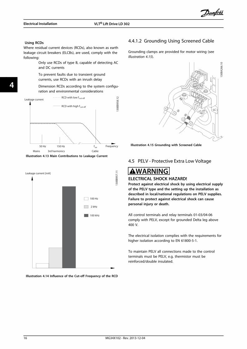
4.4 Grounding 15
4.4.1 Grounding Requirements 15
4.4.1.1 Ground Leakage Current 15
4.4.1.2 Grounding Using Screened Cable 16
4.5 PELV - Protective Extra Low Voltage 16
4.6 Wiring Schematic 18
4.6.1 Operation with Motor Contactors 18
4.6.2 Operation without Motor Contactors 19
4.7 Motor Connection 20
4.8 AC Mains Connection 20
Contents VLT® Lift Drive LD 302
MG34X102 - Rev. 2013-12-04 1
4.9 Control Wiring 20
4.9.1.1 Removing the Cover 20
4.9.1.2 Control Terminal Types 21
4.9.1.3 Relay Connection 22
4.9.1.4 Wiring to Control Terminals 23
4.9.1.5 Lift Controller MCO 361 Control Terminals 23
4.9.1.6 Using Screened Control Cables 24
4.9.1.7 Terminal 37, Safe Torque Off 25
4.9.1.8 Lift Control without Motor Contactors 26
4.10 Installation Check List 27
5 Commissioning 28
5.1 Safety Instructions 28
5.1.1 Safety Inspection 28
5.2 Applying Power to the Frequency Converter 28
5.2.1 Applying Power Procedure 28
5.3 Local Control Panel 28
5.3.1 LCP Layout 29
5.3.2 Setting LCP Display Values 29
5.3.3 Display Menu Keys 30
5.3.4 Navigation Keys 30
5.3.5 Operation Keys 31
5.3.6 Back-up and Copying Parameter Settings 31
5.3.7 Recommended Initialisation 31
5.3.8 Manual Initialisation 32
6 Programming 33
6.1 Basic Operational Programming 33
6.2 Automatic Motor Adaptation 33
6.3 Programming the Lift Application 33
6.3.1 Start and Stop Sequences 35
7 Functions 37
7.1 Brake Functions 37
7.1.1 Introduction 37
7.1.1.1 Mechanical Holding Brake 37
7.1.1.2 Dynamic Brake 37
7.1.2 Brake Resistor Requirements 37
7.1.2.1 Mechanical Brake Control 38
7.1.3 Brake Resistor Cabling 39
7.2 DCP Communication 39
Contents VLT® Lift Drive LD 302
2 MG34X102 - Rev. 2013-12-04
8 Diagnostics and Troubleshooting 40
8.1 Status Messages 40
8.2 Warnings and Alarms 40
8.3 Basic Troubleshooting 47
9 Application Examples 48
9.1 Main Contactors 48
9.2 Operation with Absolute Encoder (SSI/EnDat) 48
9.3 Check Encoder Rotation 48
9.4 Emergency Operation UPS 49
10 Special Conditions 50
10.1 Special Conditions 50
10.1.1 Extreme Running Conditions 50
10.1.2 Motor Thermal Protection 50
10.1.3 Derating 51
11 Parameter Overview 52
11.1 xx-** Active Parameters 52
11.2 Parameters 0-** Operation and Display 53
11.3 Parameters 1-** Load and Motor 54
11.4 Parameters 4-** Limits/Warnings 55
11.5 Parameters 14-** Special Functions 56
11.6 Parameters 19-** Application Parameters 56
11.7 Parameters 32-** Encoder 66
12 Specifications 67
12.1 Electrical Data 67
12.2 Ambient Conditions 70
12.3 Power Ratings, Weight and Dimensions 70
12.4 Connection Tightening Torques 73
12.5 Lift Controller MCO 361 Specifications 74
12.6 Motor Type and Associated Motor Number 76
12.6.1 Motor Type and Associated Motor Number Stored in Motor Database 76
12.6.2 Motor Type and Associated Motor Number not Stored in Motor Database 78
Index 80
Contents VLT® Lift Drive LD 302
MG34X102 - Rev. 2013-12-04 3

1 Introduction
1.1 Purpose of the Manual
This manual targets
• system designers
• installers
• service technicians
It provides detailed information for the installation andstart-up of the frequency converter. Chapter 3 MechanicalInstallation provides requirements for mechanical andelectrical installation, including
• input
• motor
• control and serial communications wiring
• control terminal functions
chapter 5 Commissioning provides detailed procedures for
• start-up
• basic operational programming
• functional testing
The remaining chapters provide information about
• user interface
• programming
• applications
• start-up troubleshooting
• specifications
1.2 Additional Resources
Supplemental publications and manuals are available fromDanfoss.See www.danfoss.com/BusinessAreas/DrivesSolutions/Documentations/Technical+Documentation.htm for listings.
1.3 Document and Software Version
This manual is regularly reviewed and updated. Allsuggestions for improvement are welcome. Table 1.1 showsthe document version and the corresponding softwareversion.
Edition Remarks Softwareversion
MG34X1 This is the first edition of this manual 6.72
Table 1.1 Document and Software Versions
1.4 Intended Use
The frequency converter is an electronic motor controllerintended for
• regulation of motor speed in response to systemfeedback or to remote commands from externalcontrollers. A power drive system consists of thefrequency converter, the motor and equipmentdriven by the motor.
• system and motor status surveillance.
The frequency converter can also be used for motorprotection.
Depending on configuration, the frequency converter canbe used in standalone applications or form part of a largerappliance or installation.
The frequency converter is allowed for use in residential,industrial and commercial environments in accordancewith local laws and standards.
NOTICEIn a residential environment this product can cause radiointerference, in which case supplementary mitigationmeasures can be required.
Foreseeable misuseDo not use the frequency converter in applications whichare non-compliant with specified operating conditions andenvironments. Ensure compliance with the conditionsspecified in chapter 12 Specifications.
1.5 Certifications
1.6 Disposal Instruction
Do not dispose of equipment containingelectrical components together withdomestic waste.Collect it separately in accordance withlocal and currently valid legislation.
Table 1.2 Disposal Instruction
Introduction VLT® Lift Drive LD 302
4 MG34X102 - Rev. 2013-12-04
11

2 Safety
The following symbols are used in this document:
WARNINGIndicates a potentially hazardous situation which couldresult in death or serious injury.
CAUTIONIndicates a potentially hazardous situation which couldresult in minor or moderate injury. It may also be usedto alert against unsafe practices.
NOTICEIndicates important information, including situations thatmay result in damage to equipment or property.
2.1 Qualified Personnel
Correct and reliable transport, storage, installation,operation and maintenance are required for the trouble-free and safe operation of the frequency converter. Onlyqualified personnel is allowed to install or operate thisequipment.
Qualified personnel is defined as trained staff, who areauthorised to install, commission, and maintain equipment,systems and circuits in accordance with pertinent laws andregulations. Additionally, the personnel must be familiarwith the instructions and safety measures described in thisdocument.
2.2 Safety Precautions
WARNINGHIGH VOLTAGEFrequency converters contain high voltage whenconnected to AC mains input power. Qualified personnelonly should perform installation, start up, andmaintenance. Failure to perform installation, start up,and maintenance by qualified personnel could result indeath or serious injury.
WARNINGUNINTENDED STARTWhen the frequency converter is connected to AC mains,the motor may start at any time. The frequencyconverter, motor, and any driven equipment must be inoperational readiness. Failure to be in operationalreadiness when the frequency converter is connected toAC mains could result in death, serious injury,equipment, or property damage.
WARNINGDISCHARGE TIMEFrequency converters contain DC-link capacitors that canremain charged even when the frequency converter isnot powered. To avoid electrical hazards, disconnect ACmains, any permanent magnet type motors, and anyremote DC-link power supplies, including battery back-ups, UPS, and DC-link connections to other frequencyconverters. Wait for the capacitors to fully dischargebefore performing any service or repair work. Theamount of wait time is listed in the Discharge Time table.Failure to wait the specified time after power has beenremoved before doing service or repair could result indeath or serious injury.
Voltage [V] Minimum waiting time (minutes)
4 15
380-400 0.25-7.5 kW[0.34-10 hp]
11-75 kW[15-100 hp]
High voltage may be present even when the warning LEDs areoff!
Table 2.1 Discharge Time
Safety VLT® Lift Drive LD 302
MG34X102 - Rev. 2013-12-04 5
2 2

3 Mechanical Installation
3.1 Equipment Pre-installation Check List
• Compare the model number of the unit on thenameplate to what was ordered to verify theproper equipment
• Ensure each of the following are rated for samevoltage:
Mains (power)
Frequency converter
Motor
• Ensure that the frequency converter outputcurrent rating is equal to or greater than motorfull load current for peak motor performance
Motor size and frequency converterpower must match for proper overloadprotection
If frequency converter rating is less thanmotor, full motor output cannot beachieved
3.2 Unpacking
3.2.1 Items Supplied
Items supplied may vary according to product configu-ration.
• Make sure the items supplied and theinformation on the nameplate correspond to theorder confirmation.
• Check the packaging and the frequency convertervisually for damage caused by inappropriatehandling during shipment. File any claim fordamage with the carrier. Retain damaged partsfor clarification.
NOTICEDo not remove the nameplate from the frequencyconverter (loss of warranty).
3.2.2 Storage
Ensure that requirements for storage are fulfilled. Refer to chapter 12.2 Ambient Conditions for further details.
3.3 Installation Environment
3.3.1 Installation Site Check List
• The frequency converter relies on the ambient airfor cooling. Observe the limitations on ambienttemperature for optimal operation.
• Before mounting the frequency converter, ensurethat the installation location has sufficientsupport strength
• Keep the frequency converter interior free fromdust and dirt. Ensure that the components stay asclean as possible. In construction areas, provide aprotective covering. Optional IP54 (NEMA 12) orIP66 (NEMA 4) enclosures may be necessary.
• Keep the manual, drawings, and diagramsaccessible for detailed installation and operatinginstructions. It is important that the manual isavailable for equipment operators.
• Locate equipment as near to the motor aspossible. Keep motor cables as short as possible.Check the motor characteristics for actualtolerances. Do not exceed
• 300 m [1,000 ft] for unshielded motorcables
• 150 m [500 ft] for screened cable.
• Consider derating for temperatures between 40°C [104 °F] and 50 °C [122 °F] and elevation1,000 m [3,300 ft] above sea level. See theequipment Design Guide for detailed information.
3.4 Mounting
3.4.1 Cooling
Ensure that top and bottom clearance for air cooling isprovided. See Illustration 3.1 for clearance requirements.
Mechanical Installation VLT® Lift Drive LD 302
6 MG34X102 - Rev. 2013-12-04
33

a
b
130B
A41
9.10
Illustration 3.1 Top and Bottom Cooling Clearance
Enclosure type A1-A5 B1-B4 C1, C3 C2, C4
a/b [mm] 100 200 200 225
Table 3.1 Minimum Airflow Clearance Requirements
3.4.2 Lifting
• To determine a safe lifting method, check theweight of the unit
• Ensure that the lifting device is suitable for thetask
• If necessary, plan for a hoist, crane, or forklift withthe appropriate rating to move the unit
• For lifting, use hoist rings on the unit, whenprovided
3.4.3 Mounting
1. Ensure that the strength of the mounting locationsupports the unit weight. The frequencyconverter allows side-by-side installation.
2. Mount the unit vertically to a solid flat surface orto the optional back plate (see Illustration 3.2 andIllustration 3.3).
3. Use the slotted mounting holes on the unit forwall mount, when provided.
130B
A21
9.11
1
Item Description
1 Back plate
Illustration 3.2 Proper Mounting with Back Plate
Install the back plate properly for required airflow to coolthe unit.
130B
A22
8.11
1
Item Description
1 Back plate
Illustration 3.3 Proper Mounting with Railings
NOTICEBack plate is needed when mounted on railings.
NOTICEImproper mounting can result in overheating andreduced performance.
Mechanical Installation VLT® Lift Drive LD 302
MG34X102 - Rev. 2013-12-04 7
3 3

4 Electrical Installation
4.1 Safety instructions
4.1.1 Requirements
WARNINGEQUIPMENT HAZARD!Rotating shafts and electrical equipment can behazardous. All electrical work must conform to nationaland local electrical codes. Only trained and qualifiedpersonnel should install, start up, and maintain theequipment. Failure to follow these guidelines couldresult in death or serious injury.
NOTICEWIRING ISOLATION!Run input power, motor wiring and control wiring in 3separate metallic conduits or use separated screenedcable for high frequency noise isolation. Failure to isolatepower, motor and control wiring could result in less thanoptimum frequency converter and associated equipmentperformance.
For safety, comply with the following requirements.
• Electronic controls equipment is connected tohazardous mains voltage. Take extreme care toprotect against electrical hazards when applyingpower to the unit.
• Run motor cables from multiple frequencyconverters separately. Induced voltage fromoutput motor cables that are run together cancharge equipment capacitors even with theequipment turned off and locked out.
Overload and equipment protection
• The frequency converter provides overloadprotection for the motor (Class 20 motorprotection). See chapter 10 Special Conditions fordetails.
• All frequency converters must be provided withshort circuit and overcurrent protection. Inputfusing is required to provide this protection, seeIllustration 4.1. If not factory supplied, the installermust provide fuses as part of installation.
L1
L1
L2
L2
L3
L3
2
91 92 931
130B
B460
.11
Item Description
1 Fuses
2 Ground
Illustration 4.1 Frequency Converter Fuses
Wire Type and Ratings
• All wiring must comply with local and nationalregulations regarding cross section and ambienttemperature requirements.
• Danfoss recommends that all power connectionsare made with a minimum 75 °C [167 °F] ratedcopper wire.
• See chapter 12.3 Power Ratings, Weight andDimensions for recommended wire sizes.
4.1.2 Cable Entries
NOTICEOther solutions are possible. Unused cable entries can besealed with rubber grommets (for IP21).
Electrical Installation VLT® Lift Drive LD 302
8 MG34X102 - Rev. 2013-12-04
44

[3]
[4]
[5]
[6]
[2]
[1]
130B
B664
.10
ItemRecommendeduse
Dimensions1) NearestmetricUL [in] [mm]
1 Mains 3/4 28.4 M25
2 Motor 3/4 28.4 M25
3 Brake/loadsharing
3/4 28.4 M25
4 Control cable 3/4 28.4 M25
5 Control cable2) 3/4 28.4 M25
6 Control cable 2) 3/4 28.4 M251) Tolerance ±0.2 mm2) Knockout hole
Illustration 4.2 A5 (IP55)
[4]
[5]
[3]
[6]
[2]
[1]
130B
B666
.10
Item Recommended use Dimensions
1 Mains M25
2 Motor M25
3 Brake/load sharing 28.4 mm1)
4 Control cable M25
5 Control cable M25
6 Control cable M251) Knock-out hole
Illustration 4.3 A5 (IP55) Threaded Gland Holes
[1]
[4]
[5]
[3]
[2]
130B
B659
.10
ItemRecommendeduse
Dimensions1) NearestmetricUL [in] [mm]
1 Mains 1 34.7 M32
2 Motor 1 34.7 M32
3 Brake/loadsharing
1 34.7 M32
4 Control cable 1 34.7 M32
5 Control cable 1/2 22.5 M201) Tolerance ±0.2 mm
Illustration 4.4 B1 (IP21)
[5]
[4]
[3]
[6]
[2]
[1]
130B
B667
.10
Item Recommended useDimensions1)
Nearest metricUL [in] [mm]
1 Mains 1 34.7 M32
2 Motor 1 34.7 M32
3 Brake/load sharing 1 34.7 M32
4 Control cable 3/4 28.4 M25
5 Control cable 1/2 22.5 M20
6 Control cable2) 1/2 22.5 M201) Tolerance ±0.2 mm2) Knockout hole
Illustration 4.5 B1 (IP55)
Electrical Installation VLT® Lift Drive LD 302
MG34X102 - Rev. 2013-12-04 9
4 4

[6]
[5]
[3]
[2]
[4]
[1]
130B
B669
.10
Item Recommended use Dimensions
1 Mains M32
2 Motor M32
3 Brake/load sharing M32
4 Control cable M25
5 Control cable M25
6 Control cable 22.5 mm 1)
1) Knockout
Illustration 4.6 B1 (IP55) Threaded Gland Holes
[4]
[3]
[5]
[2]
[1]
130B
B668
.10
ItemRecommendeduse
Dimensions1) NearestmetricUL [in] [mm]
1 Mains 1 1/4 44.2 M40
2 Motor 1 1/4 44.2 M40
3 Brake/load sharing 1 34.7 M32
4 Control cable 3/4 28.4 M25
5 Control cable2) 1/2 22.5 M201) Tolerance ±0.2 mm2) Knockout hole
Illustration 4.7 B2 (IP55)
[4]
[3]
[2]
[5]
[1]
130B
B670
.10
Item Recommended use Dimensions
1 Mains M40
2 Motor M40
3 Brake/Load Sharing M32
4 Control cable M25
5 Control cable M20
Illustration 4.8 B2 (IP55) Threaded Gland Holes
Electrical Installation VLT® Lift Drive LD 302
10 MG34X102 - Rev. 2013-12-04
44

4.2 EMC Compliant Installation
4.2.1 General Aspects of EMC Emissions
The frequency converter, motor cable and the motor generate airborne interference in the range 30 MHz to 1 GHz. Capacitive currents in the motor cable coupled with a high dU/dt from the motor voltage generate leakage currents.
Use screened motor cable to reduce radiated interference. Connect the motor cable screen to the frequency converterenclosure as well as to the motor enclosure. Use integrated screen clamps to avoid twisted screen ends (pigtails).
To reduce the interference level from the entire system (unit + installation), make motor and brake cables as short aspossible. Avoid placing cables with a sensitive signal level alongside motor and brake cables. Especially control electronicsgenerate radio interference higher than 50 MHz (airborne).
1
2
z
z
z
L1
L2
L3
PE
U
V
W
CS
I2
I1
I3
I4
CS CS CS
CS
I4
CSz PE
3 4 5 6
175Z
A06
2.12
1 Ground wire
2 Screen
3 AC mains supply
4 Frequency converter
5 Screened motor cable
6 Motor
Table 4.1
Illustration 4.9 Situation that Generates Leakage Currents
Ensure that screen currents can be conveyed back to the frequency converter. Also, ensure good electrical contact from themounting plate through the mounting screws to the frequency converter chassis.
NOTICEWhen unscreened cables are used, some emission requirements are not complied with, although the immunityrequirements are observed.
Electrical Installation VLT® Lift Drive LD 302
MG34X102 - Rev. 2013-12-04 11
4 4

4.2.2 EMC Immunity
All Danfoss frequency converters comply with the requirements for the industrial environment as well as home and officeenvironments.
Immunity tests were performed in accordance with the following standards:
• EN 61000-4-2 (IEC 61000-4-2): Electrostatic discharges (ESD): Simulation of electrostatic discharges from humanbeings.
• EN 61000-4-3 (IEC 61000-4-3): Incoming electromagnetic field radiation, amplitude modulated simulation of theeffects of radar and radio communication equipment as well as mobile communications equipment.
• EN 61000-4-4 (IEC 61000-4-4): Burst transients: Simulation of interference brought about by switching a contactor,relay, or similar devices.
• EN 61000-4-5 (IEC 61000-4-5): Surge transients: Simulation of transients brought about for example, by lightningthat strikes near installations.
• EN 61000-4-6 (IEC 61000-4-6): RF common mode: Simulation of the effect from radio-transmission equipmentjoined by connection cables.
Voltage range: 380-400 VBasic standard Burst
IEC 61000-4-4Surge
IEC 61000-4-5ESDIEC
61000-4-2
Radiated electromagneticfield
IEC 61000-4-3
RF commonmode voltageIEC 61000-4-6
Acceptance criterion B B B A ALine
4 kV CM2 kV/2 Ω DM
4 kV/12 Ω CM— — 10 VRMS
Motor 4 kV CM 4 kV/2 Ω 1) — — 10 VRMS
Brake 4 kV CM 4 kV/2 Ω1) — — 10 VRMS
Load sharing 4 kV CM 4 kV/2 Ω 1) — — 10 VRMS
Control wires 2 kV CM 2 kV/2 Ω1) — — 10 VRMS
Standard bus 2 kV CM 2 kV/2 Ω1) — — 10 VRMS
Relay wires 2 kV CM 2 kV/2 Ω 1) — — 10 VRMS
Application and fieldbusoptions
2 kV CM2 kV/2 Ω 1) — — 10 VRMS
LCP cable 2 kV CM 2 kV/2 Ω 1) — — 10 VRMS
External 24 V DC2 V CM
0.5 kV/2 Ω DM1 kV/12 Ω CM
— — 10 VRMS
Enclosure— —
8 kV AD6 kV CD
10 V/m —
Table 4.2 EMC Immunity
1) Injection on cable screenAD: Air dischargeCD: Contact dischargeCM: Common modeDM: Differential mode
EMC Test ResultsThe following test results have been obtained using a system with
• a frequency converter
• a screened cable
• a control box with potentiometer
• a motor
Electrical Installation VLT® Lift Drive LD 302
12 MG34X102 - Rev. 2013-12-04
44

• a screened motor cable
RFI filter type Conducted emission Radiated emissionStandardsandrequirements
EN 55011 Class BHousing,trades andlightindustries
Class AGroup 1Industrialenvironment
Class AGroup 2Industrialenvironment
Class BHousing,trades andlightindustries
Class AGroup 1Industrialenvironment
EN/IEC 61800-3 Category C1Firstenvironment,home andoffice
Category C2Firstenvironment,home andoffice
Category C3Secondenvironment,industrial
Category C1Firstenvironment,home andoffice
Category C2Firstenvironment,home andoffice
H1: RFI Class A1/B, Category 1/2
LD 302 0-75 kW[0-100 hp]380-480 V
IP20 50 m [164 ft] 150 m [492 ft] 150 m [492 ft] No Yes
0-7.5 kW[0-10 hp]380-480 V
IP55 50 m [164 ft] 150 m [492 ft] 150 m [492 ft] No Yes
H2: RFI Class A2, Category 3
LD 302 0-7.5 kW[0-10 hp]380-480 V
IP20 No No 5 m [16 ft] No No
11-75 kW[15-100 hp]380-480 V
IP20 No No 25 m [82 ft] No No
0-7.5 kW[0-10 hp]380-480 V
IP55 No No 5 m [16 ft] No No
H3: RFI Class A1/B, Category 1/2
LD 302 11-55 kW[15-75 hp]380-480 V
IP55 50 m [164 ft] 150 m [492 ft] 150 m [492 ft] No Yes
Table 4.3 EMC Test Results (Emission, Immunity)
H1, H2 or H3 is defined in the type code position 16-17 for EMC filtersH1 - Integrated EMC filter. Fulfils EN 55011 Class A1/B and EN/IEN 61800-3 Category 1/2H2 - No additional EMC filter. Fulfils EN 55011 Class A2 and EN/IEC 61800-2 Category 3H3 - Integrated EMC filter. Fulfils EN 55011 Class A1/B and EN/IEC 61800-3 Category 1/2.
Electrical Installation VLT® Lift Drive LD 302
MG34X102 - Rev. 2013-12-04 13
4 4

4.3 Harmonics
4.3.1 General Aspects of HarmonicsEmission
A frequency converter takes up a non-sinusoidal currentfrom mains, which increases the input current IRMS. A non-sinusoidal current is transformed with a Fourier analysisand split into sine-wave currents with different frequencies,that is, different harmonic currents In with 50 Hz basicfrequency:
I1 I5 I7
Hz 50 250 350
Table 4.4 Harmonic Currents
The harmonics do not affect the power consumptiondirectly, but increase the heat losses in the installation(transformer, cables). So, in plants with a high percentageof rectifier load, maintain harmonic currents at a low levelto avoid overload of the transformer and high temperaturein the cables.
175H
A03
4.10
Illustration 4.10 Harmonic Currents
NOTICESome of the harmonic currents might disturb communi-cation equipment connected to the same transformer orcause resonance with power-factor correction batteries.
To ensure low harmonic currents, the frequency converteris equipped with intermediate circuit coils as standard. Thisnormally reduces the input current IRMS by 40%.
The voltage distortion on the mains supply voltagedepends on the size of the harmonic currents multipliedby the mains impedance for the frequency in question.The total voltage distortion THD is calculated based on theindividual voltage harmonics using this formula:
THD % = U 25 + U 2
7 + ... + U 2N
(UN% of U)
4.3.2 Harmonics Emission Requirements
Equipment connected to the public supply network
Options Definition
1 IEC/EN 61000-3-2 Class A for 3-phase balancedequipment (for professional equipment only up to 1kW total power).
2 IEC/EN 61000-3-12 Equipment 16-75 A and profes-sional equipment as from 1 kW up to 16 A phasecurrent.
Table 4.5 Connected Equipment
4.3.3 Harmonics Test Results (Emission)
Power sizes up to PK75 in T2 and T4 comply with IEC/EN61000-3-2 Class A. Power sizes from P1K1 and up to P18Kin T2 and up to P90K in T4 comply with IEC/EN61000-3-12, Table 4. Power sizes P110 - P450 in T4 alsocomply with IEC/EN 61000-3-12 even though not requiredbecause currents are above 75 A.
Individual harmonic current In/I1 (%)
I5 I7 I11 I13
Actual(typical)
40 20 10 8
Limit forRsce≥120
40 25 15 10
Harmonic current distortion factor (%)
THD PWHD
Actual(typical)
46 45
Limit forRsce≥120
48 46
Table 4.6 Harmonics Test Results (Emission)
If the short-circuit power of the supply Ssc is greater thanor equal to:
SSC = 3 × RSCE × Umains × Iequ = 3 × 120 × 400 × Iequat the interface point between the user’s supply and thepublic system (Rsce).
It is the responsibility of the installer or user of theequipment to ensure that the equipment is connectedonly to a supply with a short-circuit power Ssc greater thanor equal to what is specified above. If necessary, consultthe distribution network operator.Other power sizes can be connected to the public supplynetwork by consultation with the distribution networkoperator.
Compliance with various system level guidelines:The harmonic current data in Table 4.6 are given inaccordance with IEC/EN61000-3-12 with reference to the
Electrical Installation VLT® Lift Drive LD 302
14 MG34X102 - Rev. 2013-12-04
44

Power Drive Systems product standard. The data may beused to calculate the harmonic currents' influence on thepower supply system and to document compliance withrelevant regional guidelines: IEEE 519 -1992; G5/4.
4.4 Grounding
4.4.1 Grounding Requirements
WARNINGGROUNDING HAZARD!Ground the frequency converter in accordance withnational and local electrical codes as well as instructionscontained within these instructions. Ground currents arehigher than 3.5 mA. Failure to ground frequencyconverter properly could result in death or serious injury.
• To ground electrical equipment properly, followall local and national electrical codes
• Proper protective earthing for equipment withground currents higher than 3.5 mA must beestablished, see chapter 4.4.1.1 Ground LeakageCurrent
• A dedicated ground wire is required for inputpower, motor power and control wiring
• Use the clamps provided with the equipment forproper ground connections
• Do not ground one frequency converter toanother in a “daisy chain” fashion
• Keep the ground wire connections as short aspossible
• Use of high-strand wire to reduce electrical noiseis recommended
• Follow motor manufacturer wiring requirements
4.4.1.1 Ground Leakage Current
Follow national and local codes regarding protectiveearthing of equipment with a leakage current > 3.5 mA. Frequency converters generate a leakage current in theground connection. A fault current in the frequencyconverter at the output power terminals might charge thefilter capacitors and cause a transient ground current.The ground leakage current depends on various systemconfigurations including RFI filtering, screened motorcables, and frequency converter power.
130B
B955
.12
a
b
Leakage current
Motor cable length
Illustration 4.11 Cable Length and Power Size Influence onLeakage Current. Pa > Pb.
130B
B956
.12
THVD=0%
THVD=5%
Leakage current
Illustration 4.12 Line Distortion Influences Leakage Current
According to EN/IEC 61800 5 1, ground wire must bereinforced, if the leakage current exceeds 3.5 mA:
• Ground wire (terminal 95) of at least 10 mm2 [8AWG]
• 2 separate ground wires both complying with thedimensioning rules
See EN/IEC61800-5-1 and EN50178 for further information.
Electrical Installation VLT® Lift Drive LD 302
MG34X102 - Rev. 2013-12-04 15
4 4
Using RCDsWhere residual current devices (RCDs), also known as earthleakage circuit breakers (ELCBs), are used, comply with thefollowing:
Only use RCDs of type B, capable of detecting ACand DC currents
To prevent faults due to transient groundcurrents, use RCDs with an inrush delay
Dimension RCDs according to the system configu-ration and environmental considerations
130B
B958
.12
f sw
Cable
150 Hz
3rd harmonics
50 Hz
Mains
RCD with low f cut-
RCD with high fcut-
Leakage current
Frequency
Illustration 4.13 Main Contributions to Leakage Current
130B
B957
.11
Leakage current [mA]
100 Hz
2 kHz
100 kHz
Illustration 4.14 Influence of the Cut-off Frequency of the RCD
4.4.1.2 Grounding Using Screened Cable
Grounding clamps are provided for motor wiring (seeIllustration 4.15).
130B
A26
6.10
+DC BR- B
MA
IN
S
L1 L2 L391 92 93
REL
AY
1
REL
AY
2
99
- LC -
U V W
MOTOR
Illustration 4.15 Grounding with Screened Cable
4.5 PELV - Protective Extra Low Voltage
WARNINGELECTRICAL SHOCK HAZARD!Protect against electrical shock by using electrical supplyof the PELV type and the setting up the installation asdescribed in local/national regulations on PELV supplies.Failure to protect against electrical shock can causepersonal injury or death.
All control terminals and relay terminals 01-03/04-06comply with PELV, except for grounded Delta leg above400 V.
The electrical isolation complies with the requirements forhigher isolation according to EN 61800-5-1.
To maintain PELV all connections made to the controlterminals must be PELV, e.g. thermistor must bereinforced/double insulated.
Electrical Installation VLT® Lift Drive LD 302
16 MG34X102 - Rev. 2013-12-04
44
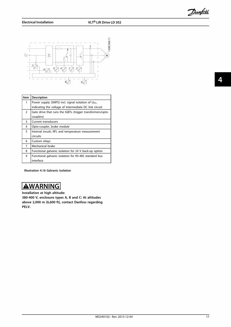
130B
C96
8.11
1
3
25 46
98
M
7
Item Description
1 Power supply (SMPS) incl. signal isolation of UDC,
indicating the voltage of intermediate DC link circuit
2 Gate drive that runs the IGBTs (trigger transformers/opto-couplers)
3 Current transducers
4 Opto-coupler, brake module
5 Internal inrush, RFI, and temperature measurementcircuits
6 Custom relays
7 Mechanical brake
8 Functional galvanic isolation for 24 V back-up option
9 Functional galvanic isolation for RS-485 standard businterface
Illustration 4.16 Galvanic Isolation
WARNINGInstallation at high altitude:380-400 V, enclosure types A, B and C: At altitudesabove 2,000 m [6,600 ft], contact Danfoss regardingPELV.
Electrical Installation VLT® Lift Drive LD 302
MG34X102 - Rev. 2013-12-04 17
4 4

4.6 Wiring Schematic
4.6.1 Operation with Motor Contactors
Illustration 4.17 is valid when 19-86 Enable SC is set to [1] Simple control.
130B
D15
4.10
Parameter19 - 50
Driveenable
K10.1 K10
K10.1
K10
K2
K1
K12
K1 K2K12
SafetyChain
K2
K1
N
Speedselect
MotorThermistorL1
L2L3PE
Directionup down
91 92 93 95
81 82 PE 96 97 98 99
50 53 55 20
20 29
37 12 1332 33 27 1 2 3 4 5 6 7 8
MCO 361
18
BrakeResistor
Motor
Brake Relay(max. 29 mA)
1 2 3 4 5 6 7 8 9 10 11 12
1 2 3 4 5 6 7 8 21X58
K1
K2
U V W PE
M3~
X57 - Input X55 - Encoder
EncoderInterface
X59 - Output
Frequency Converter
BrakeContractor
BrakeMotor
Illustration 4.17 Wiring Schematic with Contactors
Electrical Installation VLT® Lift Drive LD 302
18 MG34X102 - Rev. 2013-12-04
44

4.6.2 Operation without Motor Contactors
Illustration 4.18 is valid when 19-86 Enable SC is set to [1] Simple control.
130B
D15
5.10
Parameter19 - 50
Driveenable
K10.1 K10
K10.1
K10
K2
K1
K12
K1 K2K12
SafetyChain
K2
K1
N
Speedselect
MotorThermistorL1
L2L3PE
Directionup down
91 92 93 95
81 82 PE 96 97 98 99
50 53 55 20
20 29
37 12 1332 33 27 1 2 3 4 5 6 7 8
MCO 361
18
BrakeResistor
Motor
Brake Relay(max. 29 mA)
1 2 3 4 5 6 7 8 9 10 11 12
1 2 3 4 5 6 7 8 21X58
U V W PE
M3~
X57 - Input X55 - Encoder
EncoderInterface
X59 - Output
Frequency Converter
BrakeContractor
BrakeMotor
K2
K1
Illustration 4.18 Wiring Schematic without Contactors
Electrical Installation VLT® Lift Drive LD 302
MG34X102 - Rev. 2013-12-04 19
4 4

4.7 Motor Connection
WARNINGINDUCED VOLTAGE!Run output motor cables from multiple frequencyconverters separately. Induced voltage from outputmotor cables that are run together can chargeequipment capacitors even with the equipment turnedoff and locked out. Failure to run output motor cablesseparately could result in death or serious injury.
• For maximum cable sizes and length, see chapter 12.3 Power Ratings, Weight and Dimensions
• Comply with local and national electrical codesfor cable sizes
• Do not install power factor correction capacitorsbetween the frequency converter and the motor
• Do not wire a starting or pole-changing devicebetween the frequency converter and the motor
1. Connect the 3-phase motor wiring to terminals96 (U), 97 (V), and 98 (W).
2. Ground the cable in accordance with groundinginstructions provided.
3. Torque terminals in accordance with theinformation provided in chapter 12.4 ConnectionTightening Torques.
4. Follow motor manufacturer wiring requirements.
Illustration 4.15 represents mains input, motor, andgrounding for basic frequency converters. Actual configu-rations vary with unit types and optional equipment.
4.8 AC Mains Connection
• Size wiring based on the input current of thefrequency converter. For maximum wire sizes, see chapter 12.3 Power Ratings, Weight andDimensions.
• Comply with local and national electrical codesfor cable sizes.
• Connect 3-phase AC input power wiring toterminals L1, L2, and L3 (see Illustration 4.15).
• Depending on the configuration of theequipment, input power is connected to themains input terminals or the input disconnect.
• Ground the cable in accordance with groundinginstructions provided in chapter 4.4.1 GroundingRequirements
• All frequency converters may be used with anisolated input source as well as with groundreference power lines. When supplied from anisolated mains source (IT mains or floating delta)
or TT/TN-S mains with a grounded leg (groundeddelta), set 14-50 RFI Filter to OFF. When off, theinternal RFI filter capacitors between the chassisand the intermediate circuit are isolated. Thisisolation prevents damage to the intermediatecircuit and reduces ground capacity currents inaccordance with IEC 61800-3.
4.9 Control Wiring
• Isolate control wiring from high-powercomponents in the frequency converter.
• If the frequency converter is connected to athermistor, for PELV isolation, optional thermistorcontrol wiring must be reinforced/doubleinsulated. A 24 V DC supply voltage isrecommended.
4.9.1.1 Removing the Cover
• Remove cover plate with a screw driver. SeeIllustration 4.19.
• Or remove front cover by loosening attachingscrews. See Illustration 4.20.
130B
T248
.10
Illustration 4.19 Control Wiring Access for Enclosure Types A2,A3, B3, B4, C3 and C4
Electrical Installation VLT® Lift Drive LD 302
20 MG34X102 - Rev. 2013-12-04
44

130B
T334
.10
Illustration 4.20 Control Wiring Access for Enclosure Types A4,A5, B1, B2, C1 and C2
Enclosure types A2 and A3Encoder and I/O terminal are located behind the C optionterminal cover, see Illustration 4.21.
The lift controller bus terminals and debug terminals(RS-485) are on the top of the C-option cover. If theseconnections are used, cut out the plastic parts above theconnectors and mount the cable relief.
130B
A24
8.11
Illustration 4.21 Location of Encoder and I/O Terminals
Enclosure types A5, B1 and B2All MCO 361 terminals are located next to the control card.To get access, remove the front cover, see Illustration 4.20.
See Table 4.7 before tightening the covers.
Enclosure type IP20 IP55
A4/A5 - 2/1.5
B1 - 2.2/1.6
B2 - 2.2/1.6
C1 - 2.2/1.6
C2 - 2.2/1.6
- Does not exist
Table 4.7 Tightening Torques for Covers [Nm]/[lb-ft]
4.9.1.2 Control Terminal Types
Illustration 4.22 shows the removable frequency converterconnectors.
23
4
1
130B
B921
.11
Illustration 4.22 Control Terminal Locations
12 13 18 19 27 29 32 33 20 37
39 42 50 53 54 5561 68 69
130B
B931
.101
2 3
Illustration 4.23 Terminal Numbers
• Connector 1, terminals 12-37
• Connector 2, terminals 61, 68, 69
• Connector 3, terminals 39-55
• Connector 4, USB port for use with the MCT 10Set-up Software
• Also provided are 2 Form C relay outputs.Location depends upon the frequency converterconfiguration and size.
Electrical Installation VLT® Lift Drive LD 302
MG34X102 - Rev. 2013-12-04 21
4 4

4.9.1.3 Relay Connection
To set relay output, see parameter group 5-4* Relays.
No. 01-02 make (normally open)
01-03 break (normally closed)
04-05 make (normally open)
04-06 break (normally closed)
Table 4.8 Relay Connections
Location of relays
130B
A02
9.12
Relay2Relay1
35 36
Illustration 4.24 Terminals for Relay Connection (Enclosure Types A1, A2 and A3).
311
130B
A21
5.10
RELAY 1RELAY 2
9
9
6
03 02 01
90 05 04
Illustration 4.25 Terminals for Relay Connection(Enclosure Types A5, B1 and B2).
130B
A39
1.12
RE
LA
Y 1
RE
LA
Y 2
06
05
04
03
02
01
DC+
Illustration 4.26 Terminals for Relay Connection(Enclosure Types C1 and C2).
Electrical Installation VLT® Lift Drive LD 302
22 MG34X102 - Rev. 2013-12-04
44

4.9.1.4 Wiring to Control Terminals
Control terminal connectors can be unplugged from thefrequency converter for ease of installation, as shown inIllustration 4.22.
1. Open the contact by inserting a small screwdriverinto the slot above or below the contact, asshown in Illustration 4.27.
2. Insert the bared control wire into the contact.
3. To fasten the control wire into the contact,remove the screwdriver.
4. Ensure that the contact is not loose. Loosecontrol wiring can cause equipment faults or lessthan optimal operation.
2
1
10 m
m
130B
A31
0.10
12 13 18 19 27 29 32 33
Illustration 4.27 Connecting Control Wiring
See chapter 12.3 Power Ratings, Weight and Dimensions forcontrol terminal wiring sizes.
See chapter 4.7 Motor Connection for typical control wiringconnections.
4.9.1.5 Lift Controller MCO 361 ControlTerminals
MCO control terminals are plug connectors with screwterminals.
X55 = Encoder X56 = Not usedX57 = Digital inputsX58 = 24 V DC supplyX59 = Digital outputsX62 = Not usedX60 = DCP connector
X62
X55
X56
X57
X58
X59
2 X60
130B
B794
.10
1
Item Description Item Description
1 Terminal block 1 X58 24 V DC supply
2 Terminal block 2 X59 Digital outputs
X55 Encoder 2 X62 Not used
X56 Not used X60 DCP connector
X57 Digital inputs
Illustration 4.28 Location of Terminal Blocks on MCO 361
Terminal block 1 is used with bookstyle and terminal block2 with compact enclosure types.
Electrical Installation VLT® Lift Drive LD 302
MG34X102 - Rev. 2013-12-04 23
4 4

Terminal Terminaldescription
Lift controller functionBlock No
X55
TTLSinCos(1 Vpp)
SSI/Endat
1 +24 V supply - - -
2 +8 V supply - - -
3 +5 V supply 5 V 5 V 5 V
4 GND 0 V 0 V 0 V
5 A A A A
6 A not A not A not A not
7 B B B B
8 B not B not B not B not
9 Z/Clock H N Clock
10 Z not/Clock not H not N not Clock not
11 DATA - - DATA
12 DATA not - - DATA not
X56 1-12 Not used No function
X57
1 Digital Input Drv. enable
2 Digital InputDefined by 19-50 Run-inmode
3 Digital InputDefined by 19-50 Run-inmode
4 Digital InputDefined by 19-50 Run-inmode
5 Digital InputDefined by 19-50 Run-inmode
6 Digital InputDefined by 19-50 Run-inmode
7 Digital InputDefined by 19-50 Run-inmode
8 Digital InputDefined by 19-50 Run-inmode
9 Digital Input not used
10 Digital Input not used
X581 +24 V supply not used
2 GND not used
X59
1 Digital OutputDefined by 19-84 Functionoutput 1
2 Digital OutputSpeed level 1, < 0.8 m/s ordepending on 19-71 Set-upcounter
3 Digital OutputSpeed level 2, < 0.3 m/s ordepending on 19-71 Set-upcounter
4 Digital Output Output contactor K12
5 Digital Output CTR - Ready/fault
6 Digital OutputOver temperature. Dependson 19-70 Temp. monitor
7 Digital OutputIn position or Stand-still forsetting 19-50 Run-in modeto 6 or 7.
8 Digital Output Connected to terminal 18
Terminal Terminaldescription
Lift controller functionBlock No
X60
CS* Control Select Can DCP3 DCP4
1 RxD/TxD - P
2 RxD/TxD - N
3 0 V
4 5 V
*CS is high when transmissions are active
X62 1-5 Not used N/A
Table 4.9 Terminal Blocks
4.9.1.6 Using Screened Control Cables
Correct screeningProvide screening clamps at both ends of cable to ensurebest possible cable contact.If the ground potential between the frequency converterand the PLC differs, electric noise may occur. Solve thisproblem by fitting an equalising cable next to the controlcable. Minimum cable cross section: 16 mm2 [6 AWG].
12
PE
FC
PE
PLC
130B
B922
.12
PE PE<10 mm
Item Description
1 Min. 16 mm2 [6 AWG]
2 Equalising cable
Illustration 4.29 Correct Screening
Long control cablesWith long control cables, ground loops may occur. Toeliminate ground loops, connect one end of the screen-to-ground with a 100 nF capacitor (keep leads short).
100nF
FC
PEPE
PLC
<10 mm 130B
B609
.12
Illustration 4.30 Long Control Cables
Electrical Installation VLT® Lift Drive LD 302
24 MG34X102 - Rev. 2013-12-04
44

Avoid EMC noise on serial communicationTo reduce interference between conductors, use twisted-pair cables, see Illustration 4.31. Connect the terminal theground via an internal RC-link. The recommended methodis shown in Illustration 4.31.
PE
FC
PE
FC
130B
B923
.12
PE PE
696861
696861
12
<10 mm
Illustration 4.31 Twisted-pair Cables
4.9.1.7 Terminal 37, Safe Torque Off
PreparationRemove the bridge (jumper) between terminals 37 and 12(24 V DC). Cutting or breaking the jumper is not sufficient.
3712
130B
T314
.10
Illustration 4.32 Bridge Jumper Between Terminal 37 andTerminal 12, 24 V DC.
Electrical Installation VLT® Lift Drive LD 302
MG34X102 - Rev. 2013-12-04 25
4 4

130B
D34
3.10
Mains supply
Rectier
ControlCard
Inverter
M
VLT
COM(T20)
24V (T12)
37
K1 K2
K1
K2
K1 K2
Mechanical brake control
Switching element monitor
Control system
K1
K2
Switching element
Safety circuit with switching elements
Digitalcontrols
Illustration 4.33 Wiring in Lift Applications
System component requirementsAll components used with the Safe Torque Off functionmust comply with the general requirements of EN 81-1.
Switching device requirementsThe monitoring of the switching device is as defined inEN81-1 § 12.7.1: "The supply at terminal 37 must beinterrupted by 2 independent contacts (see block diagram).If one contactor does not open, prevent a new start at thelatest with the next direction change”.
Design of the switching elements:According to EN81 § 13..2.1.2 b) category DC -13, § 13.2.1.3(in forced contacts) and § 13.2.2.§ 14.1.1 error consideration for electrical safety devices
Electrical requirement of the switching elements:
• Air and leakage paths
• Rated shock capability 4 kV
• IEC 60 664-1 over voltage category III
• Degree of contamination 3
• Rated insulation voltage 250 V AC
The wire between terminal 12 and the first contactelement is identical to the wire from contact element 2 toterminal 37. This wire must be protected and the screenmust be connected to terminal 20 (GND). The 2 switchingelements must be installed next to each other. Electricalrequirements of the cable must comply with therequirements of EN 81-1 § 13,5. The cables must beflexible and protected Rated voltage Uo/U 300/500 V.
NOTICEThe function of the 2 independent switching elementscan also be activated with an emergency stop relay inaccordance with EN954-1 category 4 and EN81 appendixH. Perform a function test according to the elevatorcontrol system documentation.
4.9.1.8 Lift Control without MotorContactors
The Safe Torque Off function can be used as replacementfor the 2 independent contractors between frequencyconverter and motor.
Electrical Installation VLT® Lift Drive LD 302
26 MG34X102 - Rev. 2013-12-04
44

4.10 Installation Check List
Before completing installation of the unit, inspect the entire installation as detailed in Table 4.10. Check and mark the itemswhen completed.
Inspect for Description Auxiliary equipment • Look for auxiliary equipment, switches, disconnects, or input fuses/circuit breakers that may reside on the
input power side of the frequency converter or output side to the motor. Ensure that they are ready forfull-speed operation
• Check function and installation of any sensors used for feedback to the frequency converter
• Remove any power factor correction caps on motor(s)
• Adjust any power factor correction caps on the mains side and ensure that they are dampened
Cable routing • Ensure that motor wiring and control wiring are separated or screened or in 3 separate metallic conduitsfor high-frequency interference isolation
Control wiring • Check for broken or damaged wires and loose connections
• Check that control wiring is isolated from power and motor wiring for noise immunity
• Check the voltage source of the signals, if necessary
• The use of screened cable or twisted pair is recommended. Ensure that the shield is terminated correctly
Cooling clearance • Measure that top and bottom clearance is adequate to ensure proper air flow for cooling, see
Ambient conditions • Check that requirements for ambient conditions are met
Fusing and circuitbreakers
• Check for proper fusing or circuit breakers
• Check that all fuses are inserted firmly and are in operational condition and that all circuit breakers are inthe open position
Grounding • Check for sufficient ground connections that are tight and free of oxidation
• Grounding to conduit, or mounting the back panel to a metal surface, is not a suitable grounding
Input and outputpower wiring
• Check for loose connections
• Check that motor and mains are in separate conduit or separated screened cables
Panel interior • Inspect that the unit interior is free of dirt, metal chips, moisture, and corrosion
• Check that the unit is mounted on an unpainted, metal surface
Switches • Ensure that all switch and disconnect settings are in the proper positions
Vibration • Check that the unit is mounted solidly, or that shock mounts are used, as necessary
• Check for an unusual amount of vibration
Table 4.10 Installation Check List
CAUTIONPOTENTIAL HAZARD IN THE EVENT OF INTERNAL FAILURERisk of personal injury when the frequency converter is not properly closed.
• Before applying power, ensure all safety covers are in place and securely fastened.
Electrical Installation VLT® Lift Drive LD 302
MG34X102 - Rev. 2013-12-04 27
4 4

5 Commissioning
5.1 Safety Instructions
5.1.1 Safety Inspection
CAUTIONHIGH VOLTAGE!If input and output connections have been connectedimproperly, there is potential for high voltage on theseterminals. Power cables for multiple motors runimproperly in same conduit cause a risk of leakagecurrent charging capacitors within the frequencyconverter. The risk is also present even when thefrequency converter is disconnected from mains input.For initial start-up, make no assumptions about powercomponents. Follow pre-start procedures. Failure tofollow pre-start procedures could result in personalinjury or damage to equipment.
1. Input power to the unit must be OFF and lockedout. Do not rely on the frequency converterdisconnect switches for input power isolation.
2. Verify that there is no voltage on input terminalsL1 (91), L2 (92), and L3 (93), phase-to-phase, andphase-to-ground,
3. Verify that there is no voltage on outputterminals 96 (U), 97 (V), and 98 (W), phase-to-phase, and phase-to-ground.
4. Confirm continuity of the motor by measuringohm values on U-V (96-97), V-W (97-98), and W-U(98-96).
5. Check for proper grounding of the frequencyconverter as well as the motor.
6. Inspect the frequency converter for looseconnections on terminals.
7. Confirm that the supply voltage matches voltageof frequency converter and motor.
NOTICEBefore applying power to the unit, inspect the entireinstallation, see chapter 4.10.1 Installation Check List
5.2 Applying Power to the FrequencyConverter
5.2.1 Applying Power Procedure
WARNINGHIGH VOLTAGE!Frequency converters contain high voltage whenconnected to the energised DC bus. Only qualifiedpersonnel should install, start up and maintain thefreqeuncy converters. Failure to let qualified personnelinstall, start up and maintain the frequency converterscould result in death or serious injury.
WARNINGUNINTENDED START!When the frequency converter is connected to theenergised DC bus, the motor may start at any time. Thefrequency converter, motor, and any driven equipmentmust be in operational readiness. Failure to be inoperational readiness when the frequency converter isconnected to the energised DC bus could result in death,serious injury, equipment, or property damage.
1. Confirm that input voltage is balanced within 3%.If not, correct input voltage imbalance beforeproceeding. Repeat procedure after voltagecorrection.
2. Ensure optional equipment wiring, if present,matches installation application.
3. Ensure that all operator devices are in the OFFposition. Panel doors closed, or a cover mounted.
4. Apply power to the unit. DO NOT start thefrequency converter now. For units with adisconnect switch, turn to the ON position toapply power to the frequency converter.
NOTICEIf the status line in the LCP reads AUTO REMOTECOAST,it indicates that the unit is ready to operate, butis missing an input signal on terminal 27.
5.3 Local Control Panel
The local control panel (LCP) is the combined display andkeypad on the front of the unit and has several userfunctions.
Commissioning VLT® Lift Drive LD 302
28 MG34X102 - Rev. 2013-12-04
55

• Start, stop, and control speed when in localcontrol
• Display operational data, status, warnings, andcautions
• Programming frequency converter functions
• Manually Reset the frequency converter after afault when auto-reset is inactive
NOTICEAdjust the display contrast by pressing [Status] and []/[].
5.3.1 LCP Layout
The graphical LCP is divided into 4 functional groups (seeIllustration 5.1).
Autoon ResetHand
onO
StatusQuickMenu
MainMenu
AlarmLog
Cancel
InfoStatus 1(1)
1234rpm
Back
OK
43,5Hz
Run OK
43,5Hz
On
Alarm
Warn.
130B
C362
.10
a
b
c
d
1.0 A
Illustration 5.1 LCP
a. Display area.
b. Display menu keys for changing the display toshow status options, programming, or errormessage history.
c. Navigation keys for programming functions,moving the display cursor, and speed control in
local operation. Also included are the statusindicator lights.
d. Operational keys and reset.
5.3.2 Setting LCP Display Values
The display area is activated when the frequency converterreceives power from
• mains voltage
• a DC bus terminal
• a 24 V external supply
The information displayed on the LCP can be customisedfor user application.
• Each display readout has a parameter associatedwith it
• Options are selected in main menu 0-2*
• The frequency converter status at the bottom lineof the display is generated automatically and isnot selectable. See chapter 9 Application Examplesfor definitions and details.
Display Parameter number Default setting
1.1 0-20 Speed [RPM]
1.2 0-21 Motor current
1.3 0-22 Power [kW]
2 0-23 Frequency
3 0-24 Reference [%]
Table 5.1 Parameter Numbers and Default Settings for DisplayLines
1.1
2
3 1.3
1.2
130B
P041
.10
799 RPM
Auto Remote Ramping
1 (1)36.4 kw7.83 A
0.000
53.2 %
Status
Illustration 5.2 Example Showing all Display Lines
Commissioning VLT® Lift Drive LD 302
MG34X102 - Rev. 2013-12-04 29
5 5

1.1
1.2
2
1.3
130B
P062
.10
207RPM
Auto Remote Running
1 (1)
24.4 kW5.25A
6.9Hz
Status
Illustration 5.3 Example Showing a Reduced Number ofDisplay Lines
5.3.3 Display Menu Keys
Menu keys are used for menu access for parameter set-up,toggling through status display modes during normaloperation, and viewing fault log data.
130B
P045
.10
Status QuickMenu
MainMenu
AlarmLog
Illustration 5.4 Menu Keys
Key FunctionStatus Press to show operational information.
• In Auto mode, press and hold to togglebetween status readout displays
• Press repeatedly to scroll through eachstatus display
• Press and hold [Status] plus [] or [] to
adjust the display brightness
• The symbol in the upper right corner of thedisplay shows the motor rotation directionand the active set-up. This is notprogrammable.
Quick Menu Allows access to programming parameters forinitial set-up instructions and many detailedapplication instructions.
• Press to access Q2 Quick Set-up forsequenced instructions to program the basicfrequency converter set-up
• Follow the sequence of parameters aspresented for the function set-up
Main Menu Allows access to all programming parameters.
• Press twice to access top-level index
• Press once to return to the last locationaccessed
• Press and hold to enter a parameternumber for direct access to that parameter
Key FunctionAlarm log Displays a list of current warnings, the last 5
alarms, and the maintenance log.
• For details about the frequency converterbefore it entered the alarm mode, select thealarm number using the navigation keysand press [OK].
Table 5.2 Menu Key Functions
5.3.4 Navigation Keys
Navigation keys are used for programming functions andmoving the display cursor. The navigation keys alsoprovide speed control in local (hand) operation. 3 indicatorlights are also located in this area.
130B
T117
.10
OK
Back
Info
Warn
Alarm
On
Cancel
Illustration 5.5 Navigation Keys
Key Function
Back Reverts to the previous step or list in the menustructure.
Cancel Cancels the last change or command as long asthe display mode has not changed.
Info Press for a definition of the function beingdisplayed.
Navigationkeys
Use the 4 navigation keys to move between itemsin the menu.
OK Use to access parameter groups or to enable anoption.
Table 5.3 Navigation Key Functions
Commissioning VLT® Lift Drive LD 302
30 MG34X102 - Rev. 2013-12-04
55

Indicatorlight
Indicator Function
Green On The On indicator light activateswhen the frequency converterreceives power from mainsvoltage, a DC bus terminal, or a 24V external supply.
Yellow Warn When warning conditions are met,the yellow Warn indicator lightcomes on and text appears in thedisplay area identifying theproblem.
Red Alarm A fault condition causes the redalarm indicator light to flash andan alarm text is displayed.
Table 5.4 Indicator Light Functions
5.3.5 Operation Keys
Operation keys are found at the bottom of the LCP.
130B
P046
.10
Handon O Auto
on Reset
Illustration 5.6 Operation Keys
Key Function
Hand on Starts the frequency converter in local control.
• To control frequency converter speed, use thenavigation keys
• An external stop signal by control input orserial communication overrides the local handon
Off Stops the motor but does not remove power tothe frequency converter.
Auto On Puts the system in remote operational mode.
• Responds to an external start command bycontrol terminals or serial communication
• Speed reference is from an external source
Reset Resets the frequency converter manually after afault has been cleared.
Table 5.5 Operation Key Functions
5.3.6 Back-up and Copying ParameterSettings
Programming data is stored internally in the frequencyconverter.
• Data can be uploaded into the LCP memory as astorage back-up
• Once stored in the LCP, the data can bedownloaded back into the frequency converter
• Data can also be downloaded into otherfrequency converters by connecting the LCP intothose units and downloading the stored settings.(This procedure is a quick way to programmultiple units with the same settings).
• Initialisation of the frequency converter to restorefactory default settings does not change datastored in the LCP memory
WARNINGUNINTENDED START!When the frequency converter is connected to AC mains,the motor may start at any time. The frequencyconverter, motor, and any driven equipment must be inoperational readiness. Failure to be in operationalreadiness when the frequency converter is connected toAC mains could result in death, serious injury, orequipment or property damage.
CAUTIONInitialisation restores the unit to factory default settings.Any programming, motor data, localisation, andmonitoring records are lost. Uploading data to the LCPprovides a back-up before initialisation.
Restoring the frequency converter parameter settings backto default values is done by initialisation of the frequencyconverter. Initialisation can be carried out through14-22 Operation Mode or manually.
• Initialisation using 14-22 Operation Mode does notchange frequency converter data such asoperating hours, serial communication selections,personal menu settings, fault log, alarm log, andother monitoring functions
• Using 14-22 Operation Mode is generallyrecommended
• Manual initialisation erases all motor,programming, localisation, and monitoring dataand restores factory default settings
5.3.7 Recommended Initialisation
1. Press [Main Menu] twice to access parameters.
2. Scroll to 14-22 Operation Mode.
3. Press [OK].
4. Scroll to Initialisation.
Commissioning VLT® Lift Drive LD 302
MG34X102 - Rev. 2013-12-04 31
5 5

5. Press [OK].
6. Remove power to the unit and wait for thedisplay to turn off.
7. Apply power to the unit.
Default parameter settings are restored during start up.This may take slightly longer than normal.
8. Alarm 80 is displayed.
9. Press [Reset] to return to operation mode.
5.3.8 Manual Initialisation
1. Disconnect power to the unit and wait for thedisplay to turn off.
2. Press and hold [Status], [Main Menu] and [OK] atthe same time and apply power to the unit.
Factory default parameter settings are restored duringstart-up.
After powering-up the frequency converter, the LCPdisplays Operation Mode.
The LCP displays the input status terminal X.57 (0 bin=0 VDC, 1 bin=24 V DC) and the actual motor current inAmpere.
130B
D64
4.10
Autoon
ResetHandon
O
Status QuickMenu
MainMenu
AlarmLog
Back
CancelInfoOK
Status 1(1)0.00A
Operating Mode
On
Alarm
Warn.
000000000000bin
Illustration 5.7 LCP Display
X57.1
X57.2
X57.3
X57.4
X57.5
X57.6
X57.7
X57.8
X57.9
X57.10
00 00000000000 bin
130B
D35
2.10
Illustration 5.8 LCP Display, Status Terminal X.57
Commissioning VLT® Lift Drive LD 302
32 MG34X102 - Rev. 2013-12-04
55

6 Programming
6.1 Basic Operational Programming
The frequency converter requires basic operationalprogramming before running the best performance.
1. To enable motor operation, enter motornameplate data.
2. Set up the parameters in parameter group 19-**Application Parameters for the lift application.
6.2 Automatic Motor Adaptation
Automatic Motor Adaptation (AMA) is a procedure thatmeasures the electrical characteristics of the motor tooptimise compatibility between the frequency converterand the motor.
• The frequency converter builds a mathematicalmodel of the motor for regulating output motorcurrent. The procedure also tests the input phasebalance of electrical power. It compares themotor characteristics with the data entered inparameters 1-20 Motor Power [kW] to 1-25 MotorNominal Speed.
• It does not cause the motor to run and it doesnot harm the motor
• Some motors may be unable to run the completeversion of the test. In that case, select Enablereduced AMA
• If an output filter is connected to the motor,select Enable reduced AMA
• If warnings or alarms occur, see chapter 10 SpecialConditions
• Run this procedure on a cold motor for bestresults
To run AMA1. Press [Main Menu] to access parameters.
2. Scroll to parameter group 19-** ApplicationParameters.
3. Press [OK].
4. Scroll to 19-63 Motor Adaptation (AMA).
5. Press [OK].
6. Select [1] Enable complete AMA.
7. Press [OK].
8. Follow on-screen instructions.
9. The AMA runs automatically and indicates whenit is complete.
10. Press [OK] and [Cancel] to save measured values.
6.3 Programming the Lift Application
Press [Main Menu] or [Quick Menu] to set up the liftapplication parameters.
NOTICEPress [OK] and [Cancel] simultaneously to save changedparameter settings.
The following procedures describe which parameters to setand in which order.
Setting motor data for asynchronous motors
1. 19-01 Motor number.
2. 1-10 Motor Construction.
3. 1-20 Motor Power [kW].
4. parameter 1-22 Motor Voltage.
5. parameter 1-23 Motor Frequency.
6. parameter 1-24 Motor Current.
7. parameter 1-25 Motor Nominal Speed.
8. 19-02 Motor cosphi.
Setting motor data for permanent magnet motors
1. 19-01 Motor number.
2. 1-10 Motor Construction.
3. parameter 1-24 Motor Current.
4. parameter 1-25 Motor Nominal Speed.
5. parameter 1-26 Motor Cont. Rated Torque.
6. parameter 1-30 Stator Resistance (Rs).
7. parameter 1-37 d-axis Inductance (Ld).
8. parameter 1-39 Motor Poles.
9. parameter 1-40 Back EMF at 1000 RPM.
Setting the incremental encoder data
1. parameter 32-00 Incremental Signal Type.
2. parameter 32-01 Incremental Resolution.
Motor adaptation for asynchronous motors
1. 19-63 Motor adaptation (asynchron motor).
Setting the lift-construction data
1. 19-10 Traction sheave [mm].
2. 19-11 Ration 100.
3. 19-12 Suspension.
Programming VLT® Lift Drive LD 302
MG34X102 - Rev. 2013-12-04 33
6 6

Setting the control type
1. 19-86 Enable simple control.
2. 19-50 Run-in mode.
Save data and calculate internal settings
1. 19-64 Store parameter.
Pre-start checkThe 2 LEDs at terminal block X55 show the status ofchannels A and B of the incremental encoder.
Check that the LEDs are on. If the LEDs are off, there is abroken wire or a short circuit.
Starting the frequency converter in inspection mode
1. Set the speed signal (vi) and the direction signal(32/33).
2. Set the enable signal (X57.1 and 27).
The motor is now magnetised, the brake is released, andthe frequency converter starts. If the motor does not start,see chapter 8.3.1 Basic Troubleshooting.
The motor runs controlled in both directions and thefrequency converter can control the lift motor.
Start speed controller - asynchronous motor
1. Set 19-13 Brake lift delay to a value between 300and 800 ms.
2. Set 19-14 Brake delay to a value between 30 and500 ms.
3. Set 19-40 KP-gain at start to 100.
4. Set 19-42 I-time at start to 200 ms.
5. Set 19-44 Filtertime at start to 10 ms.
6. Set 19-46 Pos gain start to 0.1.
Start speed controller - permanent magnet motor
1. Set 19-13 Brake lift delay to 0 ms.
2. Set 19-14 Brake delay to a value between 300 and500 ms.
3. Set 19-40 KP-gain at start to a value between 500and 100.
4. Set 19-42 I-time at start to a value between 12and -50 ms.
5. Set 19-44 Filtertime at start to 1 ms.
6. Set 19-46 Pos gain start to a value between 0.2and 0.5.
Operation speed controller - asynchronous motor
1. Set 19-41 KP-gain at operation to 100.
2. Set 19-43 I-time operation to 200 ms.
3. Set 19-45 Filtertime operation to 10 ms.
Operation speed controller - permanent magnet motor
1. Set 19-41 KP-gain at operation to a value between10 and 70.
2. Set 19-43 I-time operation to 200 ms.
3. Set 19-45 Filtertime operation to 10 ms.
Stop behaviour
1. 19-15 Brake close delay.
2. 19-58 Delay after stop.
3. 19-59 Torque down time.
Setting of speeds
1. 19-20 Max. speed [m/s].
2. 19-21 V4 [m/s], Nominal speed.
3. 19-22 V0 [m/s], Levelling speed.
4. 19-23 Vi [m/s], Inspection speed.
5. 19-24 V3 [m/s], Intermediate speed 1.
6. 19-25 V2 [m/s], Intermediate speed 2.
7. 19-26 Vn [m/s], Relevelling speed.
8. 19-28 V1 [m/s], Intermediate speed 3.
Adjusting the motion profile
1. 19-19 Run in distance [mm].
2. 19-21 V4 [mm/s].
3. 19-22 V0 [mm/s].
4. 19-30 Acceleration [mm/s2].
5. 19-31 Deceleration [mm/s2].
6. 19-32 Start at jerk [mm(s3].
7. 19-33 Accel. jerk [mm/s3].
8. 19-34 Decel. jerk [mm/s3].
9. 19-35 Run in jerk [mm/s3].
10. 19-55 L-start acc [mm/s2].
11. 19-56 L-start speed [mm/s].
12. 19-57 L-start time [ms].
Programming VLT® Lift Drive LD 302
34 MG34X102 - Rev. 2013-12-04
66

6.3.1 Start and Stop Sequences
NOTICEStart and stop sequences in lift operating mode.
130B
D35
3.10
ReleaseI1+27+37
Start
Brakerelease
SpeedI2...I8
Directionselected
Motor on
Motor currenton
Release timeexpired
ReleaseI1+27+37
SpeedI2...I8
Set speed
DirectionUP and Down
DirectionDown
Directionchange?
Decelerateto 0 mm/s
Motoroff
Errormessage
Brakeclose
Motor offNo direction
Decelerateto 0 mm/s
Execute travelcommand
Y
N
N NN
N
N
N
N
NY
Y
Y
Y
YYY
Y
Illustration 6.1 Lift Control Start Sequence
Programming VLT® Lift Drive LD 302
MG34X102 - Rev. 2013-12-04 35
6 6

130B
D35
4.10
Falling edgerun-in signal
Target position=pos + run - in pos
Positioningmode
ReleaseI1+27+37
Positionreached
Brakeclose
Closing timeexpired?
Motor notenergized
Signal positionreached
ReleaseI1+27+37
Position reacheddelete
EndLift drive
Motorde-energized
Brakeclose
Y
N
Y
Y
Y
N N
N
Illustration 6.2 Lift Control Stop Sequence
Programming VLT® Lift Drive LD 302
36 MG34X102 - Rev. 2013-12-04
66

7 Functions
7.1 Brake Functions
7.1.1 Introduction
Brake function is applied for braking the load on themotor shaft, either as dynamic brake or static brake.
7.1.1.1 Mechanical Holding Brake
A mechanical holding brake mounted directly on themotor shaft normally performs static braking. In someapplications, the static holding torque works as staticholding of the motor shaft (synchronous permanentmotors). A PLC or a digital output from the frequencyconverter (relay or solid state) controls the holding brake.
NOTICEWhen the holding brake is included in a safety chain: A frequency converter cannot provide a safe control of amechanical brake. A redundancy circuitry for the brakecontrol must be included in the total installation.
7.1.1.2 Dynamic Brake
Establish a dynamic brake by using a brake resistor. Abrake IGBT keeps the overvoltage below a certainthreshold by directing the brake energy from the motor tothe connected brake resistor.
7.1.2 Brake Resistor Requirements
A brake resistor can handle regenerative braking andensure that energy is absorbed in the brake resistor andnot in the frequency converter. For more information, seeBrake Resistor Design Guide.
The amount of kinetic energy transferred to the resistor ineach braking period can be calculated based on the cycletime and braking time (intermittent duty cycle).
Calculate the intermittent duty cycle for the resistor asfollows:
Duty cycle = tb/T
T = cycle time in stb is the braking time in s (of the cycle time)
T
tb tat0tcta
Hz
[s]
50
830
0.5 2.5 1.3
1
2
3
4
51
2.5 2 0.5 30
Im143%123%112%83%
0
130B
D34
2.10
1 Load cycle
2 Motor current
3 Motor operation
4 Generator operation
Illustration 7.1 Intermittent Duty Cycle
380-400 VPK37-P75K
Cycle time (s) 120
Braking duty cycle at 100% torque Continuous
Braking duty cycle at over torque (150/160%) 40%
Table 7.1 Braking at High Overload Torque Level
If a 10% duty cycle is applied, the brake resistors are ableto absorb brake power for 10% of the cycle time. Theremaining 90% of the cycle time is used on dissipatingexcess heat. Danfoss offers brake resistors with duty cycleof 5%, 10% and 40%.
NOTICEMake sure that the resistor is designed to handle therequired braking time.
The max. permissible load on the brake resistor is stated asa peak power at a given intermittent duty cycle and canbe calculated as:
Rbr Ω = Udc
2
Ppeakwhere
Functions VLT® Lift Drive LD 302
MG34X102 - Rev. 2013-12-04 37
7 7

Ppeak = Pmotor x Mbr [%] x ηmotor x ηVLT[W]
As can be seen, the brake resistance depends on theintermediate circuit voltage (Udc).
Size Brakeactive
Warning beforecut out
Cut out (trip)
LD 3023x380-400V*
650 V 840 V/828 V 850 V/855 V
Table 7.2 Intermediate Circuit Voltage
* Power size dependent
NOTICEEnsure that the brake resistor is rated for 850 V.
Danfoss recommends that the brake resistance Rrec thatenables the frequency converter to brake at the highestbraking torque (Mbr(%)) of 160%. The formula can bewritten as:
Rrec Ω = Udc
2 x 100Pmotor x Mbr % xηVLT x ηmotor
ηmotor is typically at 0.90ηVLT is typically at 0.98
For 480 V frequency converters, Rrec at 160% brakingtorque is written as:
480V : Rrec = 375300Pmotor Ω 1
480V : Rrec = 428914Pmotor Ω 2
1) For frequency converters ≤ 7.5 kW [10 hp] shaft output2) For frequency converters 11-75 kW [15-100 hp] shaftoutput
NOTICEDo not apply resistor brake circuit resistances higherthan recommended by Danfoss. If a brake resistor with ahigher ohmic value is selected, the 160% braking torquemay not be achieved as the frequency converter may cutout for safety reasons.
NOTICEIf there is a short circuit in the brake transistor, preventpower dissipation in the brake resistor by using a mainsswitch or contactor to disconnect the mains for thefrequency converter. (The frequency converter cancontrol the contactor).
CAUTIONFIRE HAZARD!Do not touch the brake resistor as it can get hot while/after braking. To avoid fire, place the brake resistor in asecure environment. Failure to follow these guidelinescan cause personal injury and property/equipmentdamage.
7.1.2.1 Mechanical Brake Control
The VLT Lift Drive LD 302 features a mechanical brakecontrol specifically designed for lift applications. Output 29is used for controlling the brake.
The LD 302 automatically implements control of themechanical brake and setting of controller parameters.
WARNINGRisk of mechanical brake malfunction. Do not alter thesettings of mechanical brake function parameters.
Interrupt the power supply by 2 from each otherindependent electrical devices. These devices could be thesame as the devices for switching terminal 37 (Safe TorqueOff). If the switching elements did not open one of the 2contacts at stop of the elevator, prevent renewed startingat the latest with the next direction change.
t0 t1 t2 t3 t4 t5 t6 t7 t8 t9 t10 t11 Time
par
. 19-
13
par
. 19-
14
par
. 19-
19p
ar. 1
9-58
par
. 19-
15
1
2
3
4
5
6
7
130B
D35
1.11
par
. 19-
59
1 Motor speed
2 Motor current
3 Drive enable X57.1
4 Brake close/open
5 Control active X59.4
6 In position X59.7
7 Low speed V0
Illustration 7.2 Brake Release Sequence for Mechanical BrakeControl
Functions VLT® Lift Drive LD 302
38 MG34X102 - Rev. 2013-12-04
77

Time Description
t0 In- Position
t1 Motor control on
t2 Delay and open brake
t3 Speed reference
t4 Max. speed
t5 Deceleration command
t6 Low speed V0
t7 Stop command
t8 Positioning
t9 Brake close
t10 Motor off
t11 In- Position
Parameter Description
19-13 Brake Lift delay
19-14 Brake delay
19-19 Run in distance
19-58 Delay after Stop
19-15 Brake close delay
Table 7.3 Brake Release Sequence for Mechanical Brake Control
7.1.3 Brake Resistor Cabling
NOTICEEMC (twisted cables/screening) To reduce the electrical noise from the wires betweenthe brake resistor and the frequency converter, the wiresmust be twisted.
For enhanced EMC performance, use a metal screen.
7.2 DCP Communication
The Drive Control and Position protocol (DCP) is used forthe serial link between a lift controller and frequencyconverter, based on an RS-485 interface.
The DCP protocol distinguishes between 3 modes:
DCPComChanThis mode provides only the DCP communication channelwithout actuating the travel commands.
DCP3For lift controllers without absolute encoder system:
• Control via the serial DCP link instead of theterminal board.
• Status messages, such as fault and overtemperature, are transmitted via the DCP linkinstead of by relay.
• Monitoring speed (such as relevelling-,deceleration- and overspeed)
DCP4For lift controllers with absolute encoder system
• As DCP3, plus:
• Time-optimised direct levelling depending onremaining distance
• Millimetre accurate adjustment depending ondistance
• Supervising the deceleration at the shaft ends
Physical
• Point-to-Point link
• Frequency converter and lift controller are linked,based on RS-485 interface (semi-duplex mode).
- Baud rate: 38.400 Baud
- Parity: none
- Data bits: 8
- Stop bits: 1
Master/follower
• The lift controller is the master
• The frequency converter is the follower
• The messages are transferred in a 15 ms cycle
The LD 302 supports DCP 3 and DCP 4 protocol. Terminal60 is used as communication interface to the master.
DCP-Manufacturer Codes for VLT Lift Drive LD 302
• Frequency converter manufacturer: DanfossGmbH
• DCP-Identification: DA
Functions VLT® Lift Drive LD 302
MG34X102 - Rev. 2013-12-04 39
7 7

8 Diagnostics and Troubleshooting
8.1 Status Messages
The frequency converter automatically generates statusmessages that appear in the middle of the display.
Lift applicationmessage
Description
Act. inspection mode! Control mode is active
AMA active AMA, Automatic Motor Adaptation isactive
Auto on!! Frequency converter is not in automaticmode
Counter expired!!! Direction change counter expired
Counter low Direction change counter low/callservice
Operating Mode Lift Drive ready
Set parameter Internal parameter calculation andadjustment
MCO track error Monitor tracking error
MCO encoder error Encoder - fault, - short circuit, - wirebreakage
No motor data!! Motor data not assigned
Overspeed Shutdown due to overspeed
Overtemp heatsink Overtemperature on heatsink
Overtemp motor Overtemperature on motor
Please wait Wait until frequency converter is ready
Positioning n compl. Positioning not completed
VLT alarm There is a fault in the frequencyconverter
Table 8.1 Lift Application Messages and Descriptions
130B
D64
5.10
Status 1(1)
0.00A
Operating Mode
000000000000bin
Illustration 8.1 Status Display
8.2 Warnings and Alarms
The frequency converter monitors the condition of
• input power
• output
• motor factors
• other system performance indicators
A warning or alarm either indicates a problem internal tothe frequency converter or external failure conditions suchas
• input voltage
• motor load or temperature
• external signals
• other areas monitored by the frequency converter
WarningsA warning is issued when an alarm condition is impendingor when an abnormal operating condition makes thefrequency converter issue an alarm. A warning clears itself,when the abnormal condition has ended.
AlarmsTripThe frequency converter suspends operation to preventfrequency converter or system damage. The motor coaststo a stop. The frequency converter continues to monitorthe frequency converter status. Remedy the fault conditionand reset the frequency converter.
Resetting the frequency converter after trip/trip lockA trip can be reset in any of 4 ways:
• Press [Reset] on the LCP
• Digital reset input command
• Serial communication reset input command
• Auto reset
Trip-lockInput power is cycled. The motor coasts to a stop. Thefrequency converter continues to monitor the frequencyconverter status.
1. Remove input power to the frequency converter.
2. Correct the cause of the fault.
3. Reset the frequency converter.
A warning is displayed in the LCP along with the warningnumber.
An alarm flashes on display along with the alarm number.
Diagnostics and Troubleshoo... VLT® Lift Drive LD 302
40 MG34X102 - Rev. 2013-12-04
88

130B
P086
.11
Status0.0Hz 0.000kW 0.00A
0.0Hz0
Earth Fault [A14]Auto Remote Trip
1(1)
Illustration 8.2 Display Example of an Alarm
See chapter 5.3.4 Navigation Keys for explanation of theindicator lights.
The following warning/alarm information defines eachwarning/alarm condition, provides the probable cause forthe condition, and details a remedy or troubleshootingprocedure.
WARNING 1, 10 Volts lowThe control card voltage is below 10 V from terminal 50.Remove some of the load from terminal 50, as the 10 Vsupply is overloaded. Max. 15 mA or minimum 590 Ω.
A short circuit in a connected potentiometer or improperwiring of the potentiometer can cause this condition.
TroubleshootingRemove the wiring from terminal 50. If thewarning clears, the problem is with the wiring. Ifthe warning does not clear, replace the controlcard.
WARNING/ALARM 2, Live zero errorThis warning or alarm only appears if programmed in6-01 Live Zero Timeout Function. The signal on one of theanalog inputs is less than 50% of the minimum valueprogrammed for that input. Broken wiring or faulty devicesending the signal can cause this condition.
TroubleshootingCheck connections on all the analog inputterminals. Control card terminals 53 and 54 forsignals, terminal 55 common. MCB 101 terminals11 and 12 for signals, terminal 10 common. MCB109 terminals 1, 3, 5 for signals, terminals 2, 4, 6common).
Check that the frequency converter programmingand switch settings match the analog signal type.
Perform input terminal signal test.
WARNING/ALARM 3, No motorNo motor has been connected to the output of thefrequency converter.
WARNING/ALARM 4, Mains phase lossA phase is missing on the supply side, or the mainsvoltage imbalance is too high. This message also appearsfor a fault in the input rectifier on the frequency converter.Options are programmed at 14-12 Function at MainsImbalance.
TroubleshootingCheck the supply voltage and supply currents tothe frequency converter.
WARNING 5, DC link voltage highThe intermediate circuit voltage (DC) is higher than thehigh-voltage warning limit. The limit is dependent on thefrequency converter voltage rating. The unit is still active.
WARNING 6, DC link voltage lowThe intermediate circuit voltage (DC) is lower than the low-voltage warning limit. The limit is dependent on thefrequency converter voltage rating. The unit is still active.
WARNING/ALARM 7, DC overvoltageIf the intermediate circuit voltage exceeds the limit, thefrequency converter trips after a time.
TroubleshootingConnect a brake resistor
Extend the ramp time
Change the ramp type
Activate the functions in 2-10 Brake Function
Increase 14-26 Trip Delay at Inverter Fault
If the alarm/warning occurs during a power sag,use kinetic back-up (14-10 Mains Failure)
WARNING/ALARM 8, DC under voltageIf the DC-link voltage drops below the undervoltage limit,the frequency converter checks if a 24 V DC backup supplyis connected. If no 24 V DC backup supply is connected,the frequency converter trips after a fixed time delay. Thetime delay varies with unit size.
TroubleshootingCheck that the supply voltage matches thefrequency converter voltage.
Perform input voltage test.
Perform soft charge circuit test.
WARNING/ALARM 9, Inverter overloadThe frequency converter is about to cut out because of anoverload (too high current for too long). The counter forelectronic, thermal inverter protection issues a warning at98% and trips at 100%, while giving an alarm. Thefrequency converter cannot be reset until the counter isbelow 90%. The fault is that the frequency converter has run withmore than 100% overload for too long.
TroubleshootingCompare the output current shown on the LCPwith the frequency converter rated current.
Compare the output current shown on the LCPwith measured motor current.
Display the thermal drive load on the LCP andmonitor the value. When running above thefrequency converter continuous current rating,the counter increases. When running below the
Diagnostics and Troubleshoo... VLT® Lift Drive LD 302
MG34X102 - Rev. 2013-12-04 41
8 8

frequency converter continuous current rating,the counter decreases.
WARNING/ALARM 10, Motor overload temperatureAccording to the electronic thermal protection (ETR), themotor is too hot. Select whether the frequency converterissues a warning or an alarm when the counter reaches100% in 1-90 Motor Thermal Protection. The fault occurswhen the motor runs with more than 100% overload fortoo long.
TroubleshootingCheck for motor overheating.
Check if the motor is mechanically overloaded
Check that the motor current set in 1-24 MotorCurrent is correct.
Ensure that Motor data in parameters 1-20 to1-25 are set correctly.
If an external fan is in use, check in 1-91 MotorExternal Fan that it is selected.
Running AMA in 19-63 Automatic MotorAdaptation tunes the frequency converter to themotor more accurately and reduces thermalloading.
WARNING/ALARM 11, Motor thermistor over tempThe thermistor might be disconnected. Select whether thefrequency converter issues a warning or an alarm in1-90 Motor Thermal Protection.
TroubleshootingCheck for motor overheating.
Check if the motor is mechanically overloaded.
Check that the thermistor is connected correctlybetween either terminal 53 or 54 (analog voltageinput) and terminal 50 (+10 V supply). Also checkthat the terminal switch for 53 or 54 is set forvoltage. Check that 1-93 Thermistor Sourceselects terminal 53 or 54.
When using digital inputs 18 or 19, check thatthe thermistor is connected correctly betweeneither terminal 18 or 19 (digital input PNP only)and terminal 50.
If a KTY sensor is used, check for correctconnection between terminals 54 and 55
If using a thermal switch or thermistor, check thatthe programming of 1-93 Thermistor Resourcematches sensor wiring.
If using a KTY Sensor, check the programming of1-95 KTY Sensor Type, 1-96 KTY Thermistor Resourceand 1-97 KTY Threshold level match sensor wiring.
WARNING/ALARM 12, Torque limitThe torque has exceeded the value in 4-16 Torque LimitMotor Mode or the value in 4-17 Torque Limit GeneratorMode. 14-25 Trip Delay at Torque Limit can change this
warning from a warning-only condition to a warningfollowed by an alarm.
TroubleshootingIf the motor torque limit is exceeded during rampup, extend the ramp up time.
If the generator torque limit is exceeded duringramp down, extend the ramp down time.
If torque limit occurs while running, possiblyincrease the torque limit. Make sure that thesystem can operate safely at a higher torque.
Check the application for excessive current drawon the motor.
WARNING/ALARM 13, Over currentThe inverter peak current limit (approximately 200% of therated current) is exceeded. The warning lasts about 1.5 s,then the frequency converter trips and issues an alarm.Shock loading or quick acceleration with high inertia loadscan cause this fault. If the acceleration during ramp up isquick, the fault can also appear after kinetic back-up. Ifextended mechanical brake control is selected, trip can bereset externally.
TroubleshootingRemove power and check if the motor shaft canbe turned.
Check that the motor size matches the frequencyconverter.
Check parameters 1-20 to 1-25 for correct motordata.
ALARM 14, Earth (ground) faultThere are current from the output phases to ground, eitherin the cable between the frequency converter and themotor or in the motor itself.
TroubleshootingRemove power to the frequency converter andrepair the ground fault.
Check for ground faults in the motor bymeasuring the resistance to the ground of themotor cables and the motor with amegohmmeter.
Perform current sensor test.
ALARM 15, Hardware mismatchA fitted option is not operational with the present controlboard hardware or software.
Record the value of the following parameters and contactDanfoss:
15-40 FC Type
15-41 Power Section
15-42 Voltage
15-43 Software Version
15-45 Actual Typecode String
Diagnostics and Troubleshoo... VLT® Lift Drive LD 302
42 MG34X102 - Rev. 2013-12-04
88

15-49 SW ID Control Card
15-50 SW ID Power Card
15-60 Option Mounted
15-61 Option SW Version (for each option slot)
ALARM 16, Short circuitThere is short-circuiting in the motor or motor wiring.
Remove power to the frequency converter and repair theshort circuit.
WARNING/ALARM 22, Hoist mechanical brakeReport value shows what kind it is.0 = The torque ref. was not reached before time out.1 = Expected brake feedback not received before time out.
WARNING 23, Internal fan faultThe fan warning function is an extra protective functionthat checks if the fan is running/mounted.
TroubleshootingCheck fan resistance.
Check soft charge fuses.
WARNING 24, External fan faultThe fan warning function is an extra protective functionthat checks if the fan is running/mounted.
TroubleshootingCheck fan resistance.
Check soft charge fuses.
WARNING 25, Brake resistor short circuitThe brake resistor is monitored during operation. If a shortcircuit occurs, the brake function is disabled and thewarning appears. The frequency converter is stilloperational, but without the brake function. Removepower to the frequency converter and replace the brakeresistor.
WARNING/ALARM 26, Brake resistor power limitThe power transmitted to the brake resistor is calculated asa mean value over the last 120 s of run time. Thecalculation is based on the intermediate circuit voltage andthe brake resistance value. The warning is active when thedissipated braking is higher than 90% of the brakeresistance power.
WARNINGIf the brake transistor is short-circuited, there is a risk ofsubstantial power being transmitted to the brakeresistor.
WARNING/ALARM 27, Brake chopper faultThe brake transistor is monitored during operation and if ashort circuit occurs, the brake function is disabled and awarning is issued. The frequency converter is stilloperational but, since the brake transistor has short-circuited, substantial power is transmitted to the brakeresistor, even if it is inactive.
Remove power to the frequency converter and remove thebrake resistor.
This alarm/warning could also occur if the brake resistoroverheats.
WARNING/ALARM 28, Brake check failedThe brake resistor is not connected or not working.
ALARM 29, Heat Sink tempThe maximum temperature of the heat sink has beenexceeded. The temperature fault resets when thetemperature falls below a defined heat sink temperature.The trip and reset points are different based on thefrequency converter power size.
TroubleshootingCheck for the following conditions.
Ambient temperature too high.
Motor cables too long.
Incorrect airflow clearance above and below thefrequency converter
Blocked airflow around the frequency converter.
Damaged heat sink fan.
Dirty heat sink.
TroubleshootingCheck fan resistance.
Check soft charge fuses.
IGBT thermal sensor.
ALARM 30, Motor phase U missingMotor phase U between the frequency converter and themotor is missing.
Remove power from the frequency converter and checkmotor phase U.
ALARM 31, Motor phase V missingMotor phase V between the frequency converter and themotor is missing.
Remove power from the frequency converter and checkmotor phase V.
ALARM 32, Motor phase W missingMotor phase W between the frequency converter and themotor is missing.
Remove power from the frequency converter and checkmotor phase W.
ALARM 33, Inrush faultToo many power-ups have occurred within a short timeperiod. Let the unit cool to operating temperature.
WARNING/ALARM 36, Mains failureThis warning/alarm is only active if the supply voltage tothe frequency converter is lost and 14-10 Mains Failure isnot set to [0] No Function. Check the fuses to thefrequency converter and mains supply to the unit.
Diagnostics and Troubleshoo... VLT® Lift Drive LD 302
MG34X102 - Rev. 2013-12-04 43
8 8

ALARM 38, Internal faultWhen an internal fault occurs, a code number defined inTable 8.2 is displayed.
TroubleshootingCycle power
Check that the option is properly installed
Check for loose or missing wiring
It may be necessary to contact Danfoss service or thesupplier. Note the code number for further trouble-shooting directions.
No. Text0 Serial port cannot be initialised. Contact your
Danfoss supplier or Danfoss Service Department.
256–258 Power EEPROM data is defective or too old
512 Control board EEPROM data is defective or tooold.
513 Communication time-out reading EEPROM data
514 Communication time-out reading EEPROM data
515 Application-oriented control cannot recognise theEEPROM data.
516 Cannot write to the EEPROM because a writecommand is on progress.
517 Write command is under time-out
518 Failure in the EEPROM
519 Missing or invalid barcode data in EEPROM
783 Parameter value outside of min/max limits
1024–1279 A CAN telegram that has to be sent could not besent.
1281 Digital signal processor flash time-out
1282 Power micro software version mismatch
1283 Power EEPROM data version mismatch
1284 Cannot read digital signal processor softwareversion
1299 Option SW in slot A is too old
1300 Option SW in slot B is too old
1301 Option SW in slot C0 is too old
1302 Option SW in slot C1 is too old
1315 Option SW in slot A is not supported (not allowed)
1316 Option SW in slot B is not supported (not allowed)
1317 Option SW in slot C0 is not supported (notallowed)
1318 Option SW in slot C1 is not supported (notallowed)
1379 Option A did not respond when calculatingplatform version
1380 Option B did not respond when calculatingplatform version
1381 Option C0 did not respond when calculatingplatform version.
1382 Option C1 did not respond when calculatingplatform version.
1536 An exception in the application-oriented control isregistered. Debug information written in LCP.
No. Text1792 DSP Watch Dog is active. Debugging of power
part data, motor-oriented control data nottransferred correctly.
2049 Power data restarted
2064–2072 H081x: Option in slot x has restarted
2080–2088 H082x: Option in slot x has issued a powerup-wait
2096–2104 H983x: Option in slot x has issued a legalpowerup-wait
2304 Could not read any data from power EEPROM
2305 Missing SW version from power unit
2314 Missing power unit data from power unit
2315 Missing SW version from power unit
2316 Missing lo_statepage from power unit
2324 Power card configuration is determined to beincorrect at power-up
2325 A power card has stopped communicating whilemain power is applied
2326 Power card configuration is determined to beincorrect after the delay for power cards toregister.
2327 Too many power card locations have beenregistered as present.
2330 Power size information between the power cardsdoes not match.
2561 No communication from DSP to ATACD
2562 No communication from ATACD to DSP (staterunning)
2816 Stack overflow control board module
2817 Scheduler slow tasks
2818 Fast tasks
2819 Parameter thread
2820 LCP stack overflow
2821 Serial port overflow
2822 USB port overflow
2836 cfListMempool too small
3072–5122 Parameter value is outside its limits
5123 Option in slot A: Hardware incompatible withcontrol board hardware
5124 Option in slot B: Hardware incompatible withcontrol board hardware.
5125 Option in slot C0: Hardware incompatible withcontrol board hardware.
5126 Option in slot C1: Hardware incompatible withcontrol board hardware.
5376–6231 Out of memory
Table 8.2 Internal Fault, Code Numbers
ALARM 39, Heat Sink sensorNo feedback from the heat sink temperature sensor.
The signal from the IGBT thermal sensor is not available onthe power card. The problem could be on the power card,on the gate drive card, or the ribbon cable between thepower card and gate drive card.
Diagnostics and Troubleshoo... VLT® Lift Drive LD 302
44 MG34X102 - Rev. 2013-12-04
88

WARNING 40, Overload of digital output terminal 27Check the load connected to terminal 27 or remove short-circuit connection. Check 5-00 Digital I/O Mode and5-01 Terminal 27 Mode.
WARNING 41, Overload of digital output terminal 29Check the load connected to terminal 29 or remove short-circuit connection. Check 5-00 Digital I/O Mode and5-02 Terminal 29 Mode.
WARNING 47, 24 V supply lowThe 24 V DC is measured on the control card. The external24 V DC back-up power supply may be overloaded,otherwise contact the Danfoss supplier.
WARNING 48, 1.8 V supply lowThe 1.8 V DC supply used on the control card is outside ofallowable limits. The power supply is measured on thecontrol card. Check for a defective control card. If anoption card is present, check for an overvoltage condition.
WARNING 49, Speed limitWhen the speed is not within the specified range in4-11 Motor Speed Low Limit [RPM] and 4-13 Motor SpeedHigh Limit [RPM], the frequency converter shows a warning.When the speed is below the specified limit in 1-86 TripSpeed Low [RPM] (except when starting or stopping), thefrequency converter trips.
ALARM 50, AMA calibration failedContact Danfoss supplier or Danfoss service department.
ALARM 51, AMA check Unom and Inom
The settings for motor voltage, motor current and motorpower are wrong. Check the settings in parameters 1-20 to1-25.
ALARM 52, AMA low Inom
The motor current is too low. Check the settings.
ALARM 53, AMA motor too bigThe motor is too big for the AMA to operate.
ALARM 54, AMA motor too smallThe motor is too small for the AMA to operate.
ALARM 55, AMA parameter out of rangeThe parameter values of the motor are outside of theacceptable range. AMA cannot run.
ALARM 56, AMA interrupted by userThe user has interrupted the AMA.
ALARM 57, AMA internal faultTry to restart AMA again a number of times, until the AMAis carried out.
NOTICERepeated runs may heat the motor to a level where theresistance Rs and Rr are increased. In most cases,however, this behaviour is not critical.
ALARM 58, AMA Internal faultContact the Danfoss supplier.
WARNING 59, Current limitThe current is higher than the value in 4-18 Current Limit.Ensure that motor data in parameters 1–20 to 1–25 are setcorrectly. Possibly increase the current limit. Be sure thatthe system can operate safely at a higher limit.
ALARM 64, Voltage LimitThe load and speed combination demands a motorvoltage higher than the actual DC-link voltage.
WARNING/ALARM 65, Control card over temperatureThe cut-out temperature of the control card is 80 °C.
Troubleshooting• Check that the ambient operating temperature is
within limits
• Check for clogged filters
• Check fan operation
• Check the control card
WARNING 66, Heat sink temperature lowThe frequency converter is too cold to operate. Thiswarning is based on the temperature sensor in the IGBTmodule.
TroubleshootingThe heat sink temperature measured as 0 °C could indicatethat the temperature sensor is defective, causing the fanspeed to increase to the maximum. If the sensor wirebetween the IGBT and the gate drive card is disconnected,this warning would result. Also, check the IGBT thermalsensor.
ALARM 67, Option module configuration has changedOne or more options have either been added or removedsince the last power-down. Check that the configurationchange is intentional and reset the unit.
ALARM 68, Safe Stop activatedSafe Torque Off has been activated. To resume normaloperation, apply 24 V DC to terminal 37, then send a resetsignal (via bus, digital I/O, or by pressing [Reset].
ALARM 69, Power card temperatureThe temperature sensor on the power card is either toohot or too cold.
TroubleshootingCheck that the filters for the door fans are notblocked.
ALARM 70, Illegal FC configurationThe control card and power card are incompatible. Tocheck compatibility, contact the Danfoss supplier with thetype code of the unit from the nameplate and the partnumbers of the cards.
WARNING 76, Power unit setupThe required number of power units does not match thedetected number of active power units.
Diagnostics and Troubleshoo... VLT® Lift Drive LD 302
MG34X102 - Rev. 2013-12-04 45
8 8

WARNING 77, Reduced power modeThe frequency converter is operating in reduced powermode (less than the allowed number of inverter sections).This warning is generated on power cycle when thefrequency converter is set to run with fewer inverters, andremains on.
ALARM 79, Illegal power section configurationThe scaling card has an incorrect part number or is notinstalled. The MK102 connector on the power card couldnot be installed.
ALARM 80, Drive initialised to default valueParameter settings are initialised to default settings after amanual reset. To clear the alarm, reset the unit.
ALARM 81, CSIV corruptCSIV file has syntax errors.
ALARM 82, CSIV parameter errorCSIV failed to init a parameter.
ALARM 85, Dang fail PBProfibus/Profisafe error.
WARNING/ALARM 104, Mixing fan faultThe fan is not operating. The fan monitor checks that thefan is spinning at power-up or whenever the mixing fan isturned on.
TroubleshootingCycle power to the frequency converter todetermine if the warning/alarm returns.
All lift controller messages are shown in the LCP in short text.See Table 8.3 for more information.
Error no. LCP display Error text102 Too many CAN objects There are no more CAN objects available (CANINI).
103 Illegal axis num. Axis not in system.
105 Error not reset Error not cleared.
106 Home not done Failed to move to HOME position.
107 Home vel. zero Home velocity 0
108 Position error Position error.
109 Index not found Index pulse (encoder) not found.
110 Unknown com. Unknown command.
111 SW end limit Software end limit activated.
112 Unknown param. Illegal parameter number.
113 FC not enabled VLT Error Status
114 Too many loops. Too many nested loops.
115 Par. save failed INLONG command got an illegal string
116 Param. memory Parameters in memory are corrupted.
117 Progr. Memory Programs in memory are corrupted.
118 Reset by CPU Reset by CPU.
119 User abort User abort.
121 No more SDO chn Number of SDO channels exceeded.
125 HW end limit Limit switch activated.
149 Too many inter. Too many interrupt functions.
150 No ext. 24 V External supply is missing.
151 Too many gosub Too many nested GOSUB commands
152 Too many returns Too many RETURN commands.
154 D. out overload Digital output overloaded.
155 LINK failed LINKGPAR failed.
156 Illegal double arg. A floating point function was called with an invalid argument.
160 Internal Intr. error Interrupt happened, but interrupt address is no longer valid.
162 Memory error Error in verifying
170 Too many DIM arrays Too many DIM arrays defined.
171 Array too small Array too small
175 Out of array mem. No more memory space for the new array defined by DIM.
176 Array size wrong Array size does not correspond to the size of the existing array.
179 Waitndx time-out Time-out while waiting for index.
184 Too many ontime Too many ONTIME or ONPERIODS interrupts.
Diagnostics and Troubleshoo... VLT® Lift Drive LD 302
46 MG34X102 - Rev. 2013-12-04
88

Error no. LCP display Error text187 Out of memory Not enough memory for variables
188 CAN guarding error A guarding error happened.
189 CAN send-receive error CAN send or receive error.
190 Memory locked Memory locked
191 Illegal cam array Illegal curve array in SETCURVE.
192 Encoder error Encoder error
193 Stack overflow Stack overflow: Too many local variables or nested function calls.
194 Out of dyn. mem Out of dynamic memory.
195 Too many testindices Too many test indices in data logging command.
196 Code too old Code is too old for the current firmware.
198 Limit sw. violation Wrong direction after limit switch tripped and error reset.
199 Internal MCO fault Internal MCO fault
Table 8.3 Overview of Error Messages
8.3 Basic Troubleshooting
NOTICEPress [OK] and [Cancel] simultaneously to save changed parameter settings.
Symptom Possible Cause Test SolutionMotor is stopped with MCOTrack-error or acceleratesunexpectedly
The encoder direction is differentfrom the motor direction
Change 19-05 Encoder direction.If the problem still occurs, check34-50 Actual Position if encoderpulses are counted correctly. If not,check encoder wiring or replacethe encoder.
Motor runs controlled, butin wrong direction.
Direction of movement dependson the mechanical construction.
Change 19-04 Car direction.
Motor makes noise orvibrations
Reduce the value in 19-41 KP-gainat operation.
Motor needs too muchcurrent.
Wrong motor data may beentered.
Check that motor data is correct. If using an asynchronous motor,perform AMA.
Table 8.4 Troubleshooting
Diagnostics and Troubleshoo... VLT® Lift Drive LD 302
MG34X102 - Rev. 2013-12-04 47
8 8

9 Application Examples
9.1 Main Contactors
Prolong the life time of the main contactors by onlyswitching off the main contactors if the lift motor isdeenergised (no current load). For load-free switching ofthe main contactors, control of the lift should proceed asillustrated in Illustration 9.1 and Illustration 9.2.
Start
Main contactorsswitch on
Release + travelcommand enabled
contractorsenabled
Main N
130B
D36
4.10
Illustration 9.1 Main Contactors Power-on
Position reached
Main contactorsswitch o
Release + travelcommand disabled
130B
D36
5.10
= ”1”
End
Position reached= ”0”
Illustration 9.2 Main Contactors Power-off
9.2 Operation with Absolute Encoder (SSI/EnDat)
For running PM-motors with frequency converters, it isnecessary to know the exact rotor position. Usually, therotor position is determined by using a single-turnabsolute encoder mounted on the rotor shaft. The LD 302does not need an absolute encoder for operating PM-motors. It detects the rotor position by creating a testsignal before the first motor start. However, it is possibleto use a single-turn absolute encoder for rotor positiondetection. Switch to absolute encoder type after normalcommissioning is finished.
1. 19-08 Abs. encoder type.
2. 19-09 Abs. encoder offs.
3. 19-98 Abs. enc. position.
9.3 Check Encoder Rotation
If encoder feedback is used, check the encoder rotation.
The encoder is connected on the MCO 361 terminal blockX55.
The pulse input to the frequency converter determines theencoder direction. Clockwise direction of the shaft endmeans that channel A is 90 electrical degrees beforechannel B. Counter clockwise direction means that channelB is 90 electrical degrees before A.
130B
A11
9.10
B
A
A
B
A
B
B
A
Illustration 9.3 Encoder Direction
Application Examples VLT® Lift Drive LD 302
48 MG34X102 - Rev. 2013-12-04
99

NOTICEIf the feedback is negative, the encoder connection iswrong!
9.3.1 Encoder Connections Examples
1 2 3 12
130B
A16
3.11
754 6 8 9 10 11
24 V 8 V 5 V GND A A B B Z Z D D
Illustration 9.4 5 V Incremental Encoder (RS-422) Supplied byMCO 361
24 V 8 V 5 V GND A A B B Z Z D D
1 2 3 4 5 6 7 8 9 10 11 12
11
130B
A23
2.11
1 External 5 V supply
Illustration 9.5 5 V Incremental Encoder (RS-422) Supplied byan External Power Source
24 V 8 V 5 V GND A A B B Z Z D D
1 2 3 4 5 6 7 8 9 10 11 12
130B
A23
3.11
Illustration 9.6 24 V Absolute Encoder (SSI) Supplied by anExternal Power Source
NOTICECommon mode disturbances. When external powersupply is used, ensure the same potential between GNDon external supply and encoder connections (4) to avoidcommon mode disturbance.
9.4 Emergency Operation UPS
For emergency operation in case of mains power failure, itis possible to use a 230 V UPS. Operation with a UPSrequires a UPS control card connected on the frequencyconverter. For each lift ride, the frequency converterdetermines and stores the direction of the load.If a mains power failure occurs during a lift ride and afterapplying the UPS voltage, the lift controller starts the liftwith reduced speed (Evacuation Speed Veva) in the correctdirection to the next floor level.For more detailed information, contact Danfoss.
Application Examples VLT® Lift Drive LD 302
MG34X102 - Rev. 2013-12-04 49
9 9

10 Special Conditions
10.1 Special Conditions
10.1.1 Extreme Running Conditions
Short circuit (motor phase – phase)The frequency converter is protected against short circuits.A short circuit between 2 output phases causes anovercurrent in the converter. If the short circuit currentexceeds the permitted value, the frequency converter isturned off (Alarm 16 trip lock).See the relevant Design Guide for protection against ashort circuit at the load sharing and brake outputs.
Switching on the outputSwitching on the output between the motor and thefrequency converter may cause an error, but does notdamage the frequency converter.
Motor-generated overvoltageThe voltage in the intermediate circuit is increased whenthe motor acts as a generator. The increase in voltageoccurs in following cases:
• The load drives the motor (at constant outputfrequency from the frequency converter), that isthe load generates energy.
• During ramp-down with high moment of inertia,low friction, and too short ramp-down time forthe energy to be dissipated as a loss in thefrequency converter, the motor, and the instal-lation.
• Incorrect slip compensation setting may causehigher DC-link voltage.
• Back-EMF from PM motor operation. If coasted athigh RPM, the PM motor back-EMF maypotentially exceed the maximum voltagetolerance of the frequency converter and causedamage.
WARNINGThe frequency converter must be equipped with a breakchopper and a connected brake resistor.
Mains drop-outDuring a mains drop-out, the frequency converter keepsrunning until the intermediate circuit voltage drops belowthe minimum stop level. The minimum stop level istypically 15% below the frequency converter's lowest ratedsupply voltage. The mains voltage before the drop-out andthe motor load determines how long it takes for theinverter to coast.
10.1.2 Motor Thermal Protection
The frequency converter supports thermal motorprotection (motor overheating) by using a motorthermistor in motor windings (PTC sensor) or a mechanicalthermal switch (Klixon type). The thermistor input, terminal50 and 53, is used to connect the PTC or Klixon.
555039 42 53 54
+10
V
130B
D35
6.10
PTC/Thermistor
Illustration 10.1 Motor Thermistor
In operating mode, the lift operates as long as thethermistor input is below 3 kΩ. If the thermistor input isabove 3 kΩ, an “Over Temperature”-warning is generated.When this warning is generated, the lift cannot be started,or it is put to a hold after completion of the ride. Furtheroperation is only possible if the motor temperature isbelow the critical motor temperature.
Special Conditions VLT® Lift Drive LD 302
50 MG34X102 - Rev. 2013-12-04
1010
1330
550
250
-20°C
175H
A18
3.10
4000
3000
R(Ω)
nominel nominel -5°C nominel +5°C
[°C]
Illustration 10.2 Thermistor Input
10.1.3 Derating
In some applications, manual and/or automatic derating isnecessary.
Manual DeratingManual derating must be considered for:
• Installation at altitudes above 1,000 m [3,300 ft]
• Continuous operation at low RPM in constanttorque applications
• Ambient temperatures above 45 °C [113 °F]
Automatic DeratingThe frequency converter constantly checks for criticallevels:
• Critical high temperature on the control card orheat sink
• High motor load
• High DC-link voltage
• Low motor speed
As a response to a critical level, the frequency converteradjusts the switching frequency. For critical high internaltemperatures and low motor speed, the frequencyconverter can also force the PWM pattern to SFAVM.
Special Conditions VLT® Lift Drive LD 302
MG34X102 - Rev. 2013-12-04 51
10 10

11 Parameter Overview
11.1 xx-** Active Parameters
Table 11.1 contains active parameters for the VLT Lift DriveLD 302.
NOTICEThe Graphical LCP (LCP 102) displays all availableparameters in the Quick Menu and the Main Menu.Changes to deactivated parameters have no impact.
Press [OK] and [Cancel] simultaneously to save changedparameter settings.
ID Name Default value Unit0-** Operation/Display
0-01 Language [0] English
0-03 Regional settings [0] International
0-20Display line 1.1small [3440] Digital Inputs bin
0-21Display line 1.2small [1614] Motor Current A
0-22Display line 1.3small [1614] Motor Current A
0-23 Display line 2 large [1660] Digital Inputs bin
0-24 Display line 3 large [3450] Actual Position
1-** Load and Motor
1-10 Motor construction [0] Asynchron
1-20 Motor power Size related kW
1-22 Motor voltage Size related V
1-23 Motor frequency 50 Hz
1-24 Motor current Size related A
1-25Motor nominalspeed 1500 RPM
1-26Motor Cont. RatedTorque Size related
1-30 Stator resistance (Rs) Size related Ohm
1-31 Rotor resistance (Rr) Size related Ohm
1-33Stator leakagereactance (X1) Size related Ohm
1-34Rotor leakagereactance (X2) Size related Ohm
1-35 Main reactance (Xh) Size related Ohm
1-36Iron loss resistance(Rfe) Size related Ohm
1-39 Motor poles 4
4-** Limits/Warnings
4-16Torque limit motormode 200 %
4-17Torque limitgenerator mode 200 %
4-18 Current limit 160 %
ID Name Default value Unit14-** Special Functions
14-01 Switching frequency Size related kHz
19-** Lift Application Parameter
19-01 Motor Number 0
19-02 Motor cos Phi Size related
19-03 Encoder Autotuning
0
19-04 Car direction 0
19-05 Encoder direction 0
19-06 Encoder monitor 0
19-07 Encoder resolution 2
19-08 Absolute encodertype
0
19-09 Absolute encoderoffset
0
19-10 Traction sheave 650 mm
19-11 Ratio 100 36.85
19-12 Suspension 1
19-13 Brake Lift delay 300 ms
19-14 Brake delay 300 ms
19-15 Brake close delay 600 ms
19-16 Max. Torque 0.00 %
19-19 Run in Distance 60.0 mm
19-20 Max. Speed 1.000 m/s
19-21 V4 1.000 m/s
19-22 V0 0.100 m/s
19-23 Vi 0.300 m/s
19-24 V3 0.800 m/s
19-25 V2 0.300 m/s
19-26 Vn 0.010 m/s
19-27 Floor level distance 5.0 mm
19-28 V1 0.200 m/s
19-30 Acceleration mm/s² 0.700 mm/s²
19-31 Deceleration mm/s² 1.000 mm/s²
19-32 Start jerk 0.600 mm/s³
19-33 Acceleration jerk 0.600 mm/s³
19-34 Deceleration jerk 1.000 mm/s³
19-35 Run in jerk 0.400 mm/s³
19-38 Comfort 0
19-40 KP – gain at start 100
19-41 KP – gain atoperation
100
19-42 I time at start 200.0 ms
19-43 I time operation 200.0 ms
19-44 Filtertime start 1.0 ms
19-45 Filtertime operation 10.0 ms
19-46 Position gain start 0.0000
19-50 Run – in Mode 0
Parameter Overview VLT® Lift Drive LD 302
52 MG34X102 - Rev. 2013-12-04
1111

ID Name Default value Unit19-55 L- start acceleration 0.020 m/s²
19-56 L- start speed 0.050 m/s
19-57 L- start time 200 ms
19-58 Delay after stop 100 ms
19-59 Torque down time 200 ms
19-60 Test – Run Mode 0
19-62 Open loop 0
19-63 Motor adaption 0
19-64 Store Parameter 0
19-65 Brake monitor not active
19-66 Digital Serial 0
19-67 Function Relay 1 1
19-68 Time delay coast 5 ms
19-69 Sync Position 0
19-70 Temp monitor 0
19-71 Set up counter 0
19-72 DCP4 corr. factor 1.000
19-73 DCP4 slip compen-sation
0 %
19-80 Log No 1
19-81 Error code 0
19-82 Error Time 0 h
19-83 Reset Error log 0
19-84 Function output 1 0
19-86 Enable SC 0
19-90 Software Version Version No.
19-92 Status
19-93 Dir change cnt 1 -1
19-94 Dir change cnt 2 0
19-98 Abs enc position 0
19-99 Distance during dec. 0
32-** Lift Controller Basic Settings
32-00Incremental SignalType [1] RS422 (5 V TTL)
32-01IncrementalResolution 1024
Table 11.1 Lift Application Parameters
11.2 Parameters 0-** Operation and Display
0-01 Language
Option: Function:[0] * English Defines the display language. When setting
the language to [0] English or [1] Deutsch,status display messages and parameterdescriptions are shown in the selectedlanguage. When setting the language to one of theother options, status display messages andparameters in parameter group 19-**Application Parameters are shown in English.
[1] * Deutsch
[2] * Français
0-01 Language
Option: Function:[3] * Dansk
[4] * Española
[5] * Italiano
[6] * Svenska
[7] * Nederlands
[20] * Suomi
0-03 Regional Settings
Option: Function:
NOTICEThis parameter cannot be adjusted whilethe motor is running.
[0] * Interna-tional
Activates 1-20 Motor Power [kW] for setting themotor power in kW and sets the default value ofparameter 1-23 Motor Frequency to 50 Hz.
[1] US Activates 1-20 Motor Power [kW] for setting themotor power in hp and sets the default value of parameter 1-23 Motor Frequency to 60 Hz.
0-20 Display Line 1.1 Small
Option: Function:Select a variable for display in line 1, leftposition.
[3440] * Digital Inputs
0-21 Display Line 1.2 Small
Option: Function:Select a variable for display in line 1,middle position.
[1614] * Motor Current
0-22 Display Line 1.3 Small
Option: Function:Select a variable for display in line 1,right position.
[1614] * Motor Current
0-23 Display Line 2 Large
Option: Function:Select a variable for display in line 2.
[1660] * Digital Inputs
0-24 Display Line 3 Large
Option: Function:Select a variable for display in line 3.
[3450] * Actual Position
Parameter Overview VLT® Lift Drive LD 302
MG34X102 - Rev. 2013-12-04 53
11 11

11.3 Parameters 1-** Load and Motor
1-10 Motor Construction
Option: Function:Select the motor design type.
[0] Asynchron For asynchronous motors.
[1] PM, non-salientSPM
For salient or non-salient PM motors.PM motors are divided into 2 groups, witheither surface-mounted (non-salient) orinterior (salient) magnets.
1-20 Motor Power [kW]
Range: Function:Sizerelated*
[Applicationdependant]
Enter the nominal motor power in kWaccording to the motor nameplatedata. The default value corresponds tothe nominal rated output of the unit.This parameter is visible in LCP if parameter 0-03 Regional Settings is [0]International.
1-21 Motor Power [hp]
Range: Function:Size-related*
[Applicationdependant]
Enter the nominal motor power in hpaccording to the motor nameplatedata. The default value corresponds tothe nominal rated output of the unit.This parameter is visible in LCP if parameter 0-03 Regional Settings is [1]US
1-22 Motor Voltage
Range: Function:Sizerelated*
[ 10 -1000 V]
Enter the nominal motor voltageaccording to the motor nameplatedata. The default value corresponds tothe nominal rated output of the unit.
1-23 Motor Frequency
Range: Function:Sizerelated*
[20 -1000Hz]
Min - Max motor frequency: 20-1000 Hz.Select the motor frequency value from themotor nameplate data. If a value differentfrom 50 Hz or 60 Hz is selected, adapt theload independent settings in 1-50 MotorMagnetisation at Zero Speed to 1-53 ModelShift Frequency. For 87 Hz operation with230/400 V motors, set the nameplate datafor 230 V/50 Hz. To run at 87 Hz, adapt4-13 Motor Speed High Limit [RPM] and3-03 Maximum Reference.
1-24 Motor Current
Range: Function:Sizerelated*
[ 0.10 -10000.00 A]
Enter the nominal motor currentvalue from the motor nameplate
1-24 Motor Current
Range: Function:data. The data are used forcalculating torque, motorprotection etc.
1-25 Motor Nominal Speed
Range: Function:Sizerelated*
[10 - 60000RPM]
Enter the nominal motor speedvalue from the motor nameplatedata. The data are used forcalculating motor compensations.nm,n = ns - nslip.
1-26 Motor Cont. Rated Torque
Range: Function:Sizerelated*
[0.1 -10000 Nm]
Enter the value from the motornameplate data. The default valuecorresponds to the nominal ratedoutput. This parameter is available when1-10 Motor Construction is set to [1] PM,non-salient SPM, i.e. the parameter isvalid for PM and non-salient SPMmotors only.
1-30 Stator Resistance (Rs)
Range: Function:Sizerelated*
[ 0.0140 -140.0000 Ohm]
Set the line to common statorresistance value. Enter the valuefrom a motor datasheet orperform an AMA on a cold motor.
NOTICEParameters 1-31 to 1-35 do not have effect when 1-10Motor Construction is set to [1] PM, non-salient SPM.
1-31 Rotor Resistance (Rr)
Range: Function:Size related* [ 0.0100 -
100.0000 Ohm]Set the rotor resistance valueRr to improve shaft
performance.
1-33 Stator Leakage Reactance (X1)
Range: Function:Size related* [ 0.0400 - 400.0000
Ohm]Set the stator leakagereactance of the motor.
1-34 Rotor Leakage Reactance (X2)
Range: Function:Size related* [ 0.0400 - 400.0000
Ohm]Set the rotor leakagereactance of the motor.
Parameter Overview VLT® Lift Drive LD 302
54 MG34X102 - Rev. 2013-12-04
1111

1-35 Main Reactance (Xh)
Range: Function:Size related* [ 1.0000 - 10000.0000
Ohm]Set the main reactance ofthe motor.
NOTICE1. Run an AMA on a cold motor. The frequency
converter measures the value from the motor.
2. Enter the X1, X2 and Xh values manually. Obtainthe value from the motor supplier.
3. Use the X1, X2 and Xh default setting. Thefrequency converter establishes the settingbased on the motor nameplate data.
1-36 Iron Loss Resistance (Rfe)
Range: Function:Sizerelated*
[ 0 -10000.000Ohm]
To compensate for iron loss in themotor, enter the equivalent iron lossresistance (RFe) value.
The RFe value cannot be found by
performing an AMA.The RFe value is especially important in
torque control applications. If RFe is
unknown, leave parameter 1-36 IronLoss Resistance (Rfe) on default setting.
1-37 d-axis Inductance (Ld)
Range: Function:Sizerelated*
[0.0 -1000.0mH]
Enter line to common direct axisinductance of the PM motor. Obtain thevalue from the permanent magnet motordatasheet.If only line-line data are available, dividethe line-line value by 2 to achieve theline-common (star point) value. Alterna-tively measure the value with aninductance meter, this also takes theinductance of the cable into account.Divide the measured value by 2 and enterthe result.This parameter is only active when1-10 Motor Construction has the value [1]PM, non-salient SPM (Permanent MagnetMotor).For a selection with one decimal, use thisparameter. For a selection with threedecimals, use 30-80 d-axis Inductance (Ld).
1-39 Motor Poles
Range: Function:Size related* [2 - 128 ] Enter the number of motor poles.
Poles ~nn@ 50 Hz ~nn@ 60 Hz
2 2700-2880 3250-3460
4 1350-1450 1625-1730
6 700-960 840-1153
Table 11.2 Number of Motor Poles
Table 11.2 shows the number of poles for normal speedranges of various motor types. Define motors designed forother frequencies separately. The motor pole value isalways an even number and refers to the total number ofpoles. The frequency converter bases the initial setting of parameter 1-39 Motor Poles on parameter 1-23 MotorFrequency and parameter 1-25 Motor Nominal Speed.
1-40 Back EMF at 1000 RPM
Range: Function:Sizerelated*
[0 -9000 V]
Set the nominal back EMF for the motorwhen running at 1,000 RPM.Back EMF is the voltage generated by a PMmotor when no frequency converter isconnected and the shaft is turnedexternally. Back EMF is normally specifiedfor nominal motor speed or for 1,000 RPMmeasured between 2 lines. If the value isnot available for a motor speed of 1,000RPM, calculate the correct value as follows.If back EMF is for example. 320 V at 1,800RPM, it can be calculated at 1,000 RPM asfollows:
ExampleBack EMF 320 V at 1,800 RPM. Back EMF=(Voltage/RPM)*1,000 = (320/1800)*1,000 =178.
This parameter is only active when1-10 Motor Construction is set to [1] PMmotor (Permanent Magnet Motor).
11.4 Parameters 4-** Limits/Warnings
4-16 Torque Limit Motor Mode
Range: Function:200%* [Application
dependant]The function limits the torque onthe shaft to protect themechanical installation.
4-17 Torque Limit Generator Mode
Range: Function:200%* [Application
dependant]The function limits the torque onthe shaft to protect themechanical installation.
Parameter Overview VLT® Lift Drive LD 302
MG34X102 - Rev. 2013-12-04 55
11 11

4-18 Current Limit
Range: Function:200%* [Application
dependant]This function is a true current limitfunction that continues in the oversynchronous range. However, due tofield weakening, the motor torque atcurrent limit drops accordingly, when thevoltage increase stops above thesynchronised motor speed.
11.5 Parameters 14-** Special Functions
14-01 Switching Frequency
Select the converter switching frequency. Changing the switchingfrequency can reduce acoustic noise from the motor. Defaultvalues depend on power size.
Option: Function:[0] 1.0 kHz
[1] 1.5 kHz Default switching frequency for355-1200 kW [500-1600 hp], 690V
[2] 2.0 kHz Default switching frequency for250-800 kW [350-1075 hp], 400 Vand 37-315 kW [50-450 hp], 690V
[3] 2.5 kHz
[4] 3.0 kHz Default switching frequency for18.5-37 kW [25-50 hp], 200 V and37-200 kW [50-300 hp], 400 V
[5] 3.5 kHz
[6] 4.0 kHz Default switching frequency for5.5–15 kW [7.5-20 hp], 200 V and11-30 kW [15-40], 400 V
[7] 5.0 kHz Default switching frequency for0.25–3,7 kW [0.34-5 hp], 200 Vand 0.37-7.5 kW [0.5-10 hp], 400V
[8] 6.0 kHz
[9] 7.0 kHz
[10] 8.0 kHz
[11] 10.0 kHz
[12] 12.0kHz
[13] 14.0 kHz
[14] 16.0kHz
NOTICEThe output frequency value of the frequency convertermust never exceed 1/10 of the switching frequency.When the motor is running, adjust the switchingfrequency in parameter 14-01 Switching Frequency tominimise motor noise.
NOTICETo avoid a trip, the frequency converter can adapt theswitching frequency automatically.
11.6 Parameters 19-** ApplicationParameters
19-01 Motor Number
Option: Function:Select the ASM or PM motor type stored in LD 302motor type database. By selecting a certain motortype, all required motor data are set automaticallywithin the LD 302. See Table 12.21 and Table 12.22for motor type and associated motor number.
1. Enter motor type number.
2. Save the selected motor type.
3. Press [OK] and [Cancel] to save thesettings.
If selecting [0], enter the following parameter forASM or PM motors.
ASM motors
• 1-10 Motor Construction
• 1-20 Motor Power [kW]
• parameter 1-22 Motor Voltage
• parameter 1-23 Motor Frequency
• parameter 1-24 Motor Current
• parameter 1-25 Motor Nominal Speed
• 19-02 Motor Cos Phi
• 19-63 Motor Adaptation
PM motors
• 1-10 Motor Construction
• parameter 1-23 Motor Frequency
• parameter 1-24 Motor Current
• parameter 1-26 Motor Cont. Rated Torque
• parameter 1-30 Stator Resistance (Rs)
• parameter 1-37 d-axis Inductance (Ld)
• parameter 1-39 Motor Poles
• parameter 1-40 Back EMF at 1000 RPM
[0] * No standard ASM or PM motor within LD 302motor database.
[XXX] [1 –120]
The entered value enables a certain ASM or PMmotor type within the LD 302 motor database.
19-02 Motor Cos Phi
Range: Function:Sizerelated*
[65-95] Set the motor cos phi value, multiplied by100. The input of the cos phi value causesautomatically a new calculation of theadvanced motor data, parameter 1-30 Stator
Parameter Overview VLT® Lift Drive LD 302
56 MG34X102 - Rev. 2013-12-04
1111

19-02 Motor Cos Phi
Range: Function:Resistance (Rs) to parameter 1-35 MainReactance (Xh).
19-03 Encoder Autotuning
Option: Function:Detect the direction of the encoderrotation.
[0] * No function Not active
[1] EncoderAutotuning
Determine encoder rotation direction.The detected encoder direction isautomatically stored in 19-06 EncoderMonitor.
19-04 Car Direction
Option: Function:Change the travel direction of the elevatorcar.
[0] * No function The car direction is not changed.
[1] Car direction The car direction is changed.
19-05 Encoder Direction
Option: Function:Change the travel direction of the encoderwithout swapping 2 phases in the motorcable. Before switching to operating mode, set19-62 Open Loop to [0] Closed loop control.
[0] * No function The encoder direction is not changed.
[1] Encoderdirection
The encoder direction is changed.
NOTICETo start the car in upwards direction, motor shaftrotation must be clockwise.
19-06 Encoder Monitor
Option: Function:Enables the encoder monitoring for
• encoder voltage
• wire break
• encoder error
[0] * No function The encoder monitoring is not active.
[1] Encoder monitor The encoder monitoring is active.
19-07 Encoder Resolution
Range: Function:2* [2-8] Set the factor n to calculate the encoder resolution.
Encoder resolution=resolution x 2n
For TTL encoder, set fixed n=2.
For SinCos encoder, set 22 or 23.
19-08 Absolute Encoder Type
Select the absolute encoder type for 13-bit single turn encoder.
Option: Function:[0] * None
[1] SSI
[2] EnDat
19-09 Absolute Encoder Offset
Select the absolute encoder type offset.
Range: Function:0* [8192-0002]
NOTICEBefore setting up parameters 19-10 to 19-12:
1. Enter motor data.
2. Set the parameters.
3. Press [OK] + [Cancel] to save the parametersettings.
The frequency converter uses the values for calculatingmaximum speed.
19-10 Traction sheave
Range: Function:650 mm* [100-2500 mm ] Set the traction sheave diameter in
mm.
19-11 Ratio 100
Range: Function:36.85* [99.99-1.00 ] Set the gear ratio value, multiplied by 100.
19-12 Suspension
Range: Function:1* [2-8] Specifies the number of suspensions.
19-13 Brake Lift Delay
Range: Function:
300ms*
[6000-20ms]
Set the delay time in ms for the lift brake.Ensure that the motor is 100% premagnetisedto take over the maximum load after brakerelease. For asynchronous motors (ASM), thefrequency converter assigns a delay time of300 ms to 1,500 ms, depending on motorsize. See also chapter 7.1.2.1 Mechanical BrakeControl.
19-14 Brake Delay
Range: Function:300ms*
[3000-50ms]
Set the time delay in ms for the brakerelease after the 24 V output signal onterminal 29. See alsochapter 7.1.2.1 Mechanical Brake Control.
Parameter Overview VLT® Lift Drive LD 302
MG34X102 - Rev. 2013-12-04 57
11 11

19-15 Brake Close Delay
Range: Function:600ms*
[6000-50ms]
Set the time delay in ms for closing the brakeafter switching the output signal from 24 Vto 0 V on terminal 29. The time delay ensuresthat the motor remains energised longenough to close the brake. See alsochapter 7.1.2.1 Mechanical Brake Control.
19-16 Max. Torque
Range: Function:0.00%ms*
[200 to-200%]
Set the time delay in ms for closing the brakeafter switching the output signal from 24 V to0 V, on terminal 29. This time delay ensuresthat the motor is energised long enough toclose the brake. See alsochapter 7.1.2.1 Mechanical Brake Control.When set to 0, there is no function. When setabove or below 0, the function is active.
19-19 Run in Distance
Range: Function:60.0mm*
[50000-0mm]
Set the run-in distance in mm. See alsochapter 7.1.2.1 Mechanical BrakeControl.
Parameter Symbol
19-20 Max. sSpeed
19-21 Nominal Speed V4
19-22 Levelling Speed V0
19-23 Inspection Speed Vi
19-24 Intermediate Speed 1 V3
19-25 Intermediate Speed 2 V2
19-26 Relevelling Speed Vn
19-28 Intermediate Speed V1
Evacuation Speed, Fixed (V0) Veva
Table 11.3 Lift Speed Parameters
19-20 Max. Speed
Range: Function:1.000m/s*
[20-0.01m/s]
Set the max. speed in m/s for the lift.Depending on the nominal motor speedand the settings in parameters 19-10 to19-12, the maximum speed is limited to125% of the rated motor speed.
19-21 V4, Nominal Speed
Range: Function:1.000 m/s* [20-0.01 m/s] Set the nominal speed V4, in m/s.
19-22 Levelling Speed, V0
Range: Function:0.100 m/s* [20-0.01 m/s] Set the levelling speed V0, in m/s.
19-23 Inspection Speed, Vi
Range: Function:0.300 m/s* [0.630-0.01 m/s] Set the inspection speed Vi in m/s.
19-24 Intermediate Speed, V3
Range: Function:0.800 m/s* [20-0.01 m/s] Set the intermediate speed V3 in m/s.
19-25 Intermediate Speed, V2
Range: Function:0.300 m/s* [20-0.01 m/s] Set the intermediate speed V2, in
m/s.
19-26 Relevelling Speed, Vn
Range: Function:0.010 m/s* [20-0.01 m/s] Set the relevelling speed Vn, in m/s.
19-27 Floor level distance
Range: Function:5.0 mm* [2000-10 mm] Set the floor level distance, in mm.
19-28 Intermediate Speed, V1
Range: Function:0.200 m/s* [20-0.01 m/s] Set the intermediate speed V1 in m/s.
NOTICEChanging parameter setting of 19-38 Comfort causeschanges to the parameter settings in 19-30 Accelerationmm/s2, 19-31 Deceleration mm/s2, 19-32 Start Jerk, 19-33,19-34 Deceleration Jerk and 19-35 Run in Jerk.
NOTICEA change of the parameter settings for 19-31Deceleration mm/s2, 19-34 Deceleration Jerk and 19-35Run in Jerk, changes the braking distance.
19-30 Acceleration mm/s2
Range: Function:
0.700 m/s2* [2-0.1 m/s2] Set the maximum acceleration for the
selected speed in m/s2
19-31 Deceleration mm/s2
Range: Function:
1.000 m/s2* [2-0.1 m/s2] Set the maximum deceleration in
mm/s2
19-32 Start Jerk
Range: Function:0.600
m/s3*
[9.990-0.1
m/s3]Set the start jerk in mm/s3. The start-upjerk is an essential comfort feature.Suggestion for start jerk setting:
• gentle: < 0.3 m/s3
• normal: 0.6 m/s3
• dynamic: > 1.0 m/s3
Parameter Overview VLT® Lift Drive LD 302
58 MG34X102 - Rev. 2013-12-04
1111
19-33 Acceleration Jerk
Range: Function:
0.600 m/s3* [9.990-0.1 m/s3] Sets the acceleration jerk in m/s3.
19-34 Deceleration Jerk
Range: Function:1.000
m/s3*
[9.990-0.1
m/s3]Set the deceleration jerk in mm/s3. Therun-jerk is activated, when the levellingspeed is reached. Suggestions fordeceleration jerk setting:
• gentle: < 0.6 m/s3
• normal: 1.0 m/s3
• dynamic: > 1.4 m/s3
19-35 Run in Jerk
Range: Function:0.400
m/s3*
[9.990-0.1
m/s3]Set the run-in jerk in mm/s3. The run-injerk is activated when the levellingspeed is reached. Suggestions for run-injerk setting:
• gentle: < 0.2 m/s3
• normal: 0.4 m/s3
• dynamic: > 0.6 m/s3
NOTICEChanging the settings of 19-38 Comfort, changes thesettings in 19-30 Acceleration mm/s2, 19-31 Decelerationmm/s2, 19-32 Start Jerk, 19-33 Acceleration Jerk, 19-34Deceleration Jerk and 19-35 Run in Jerk.
19-38 Comfort
Option: Function:Set the travelling comfort.
[0] * Normal Normal comfort
[1] Gentle Gentle comfort
[2] Dynamic Dynamic comfort
[3] No function
01
2
3
4
5
6
78
9
t0 t1 t2 t3 t4 t5 t6 t7 t8 t9 t10
v[m/s]
t [s]
130B
D34
5.10
Illustration 11.1 Ramp Parameter for Acceleration,Deceleration and Jerk
Identifier Time period Parameter Description
0 t0-t2 19-55 to 19-57 Line start
1 t1-t2 19-32 Start jerk
2 t2-t3 19-30 Acceleration
3 t3-t4 19-33 Accel. jerk
4 t4-t5 19-21 V4
5 t5-t6 19-34 Decel. jerk
6 t6-t7 19-31 Deceleration
7 t7-t8 19-35 Run in jerk
8 t8-t9 Low Speed V0
9 t9-t10 19-19 Run in Distance
Table 11.4 Legend to Illustration 11.1Ramp Parameter Description
1
2
3
Par.19-4019-4219-4419-46
Par.19-4119-4319-45
Par.19-14
t0 t1 t2 t3 t/s
130B
D34
4.10
Illustration 11.2 Control Parameter Start/Operations
1 Actual speed
2 Mechanical brake
3 Motor active
Table 11.5 Legend to Illustration 11.2
19-40 KP Gain at Start
Range: Function:100* [5000-1] Set the PID proportional gain at start. Increase
the KP-start value if the motor rotatesbackwards after start.
19-41 KP Gain at Operation
Range: Function:100* [5000-1] Set the PID proportional gain for operation,
travel. Decrease the KP- operating value in caseof motor noise during travelling. Increase theKP- operating value in case of motor oscillationsduring travelling.
Parameter Overview VLT® Lift Drive LD 302
MG34X102 - Rev. 2013-12-04 59
11 11

19-42 TI Time at Start
Range: Function:200* [500-2 ms] Set the PID integral time in ms at start.
Increase the time value if after start the motorrotates backwards.
19-43 TI Time Operation
Range: Function:200* [500-2 ms] Set the PID integral time in ms for operation,
travel.
19-44 Filtertime Start
Range: Function:1.0ms*
[500-1ms]
NOTICESevere filtering can cause bad dynamicperformance.
Set a time constant for the speed control low-pass filter. The low-pass filter improves steady-state performance and dampens oscillations onthe feedback signal. This is an advantage if thereis a great amount on noise in the system, seeIllustration 11.3. For example, if a time constant (τ)of 100 ms is programmed, the cut-off frequencyfor the low-pass filter is 1/0.1= 10 RAD/s. Thisvalue corresponds to (10/2 x π) = 1.6 Hz. The PIDregulator only regulates a feedback signal thatvaries by a frequency of less than 1.6 Hz. If thefeedback signal varies by a higher frequency than1.6 Hz, the PID regulator does not react.
0.6
0.6
fg = 10 Hz
175Z
A29
3.11Feedback
Disturbed feedback signal
t (Sec.)
t (Sec.)
Filtered feedback signal
Lowpass lter
Feedback
Illustration 11.3 Filtering Feedback through Lowpass Filter
19-45 Filtertime Operation
Range: Function:10.0 ms* [500-1 ms] Set the speed controller filter time for
operation mode.
19-46 Position Gain Start
Range: Function:0.0000* [500-1 ms] Select the position gain start.
Parameter Overview VLT® Lift Drive LD 302
60 MG34X102 - Rev. 2013-12-04
1111

19-50 Run-in Mode
Range: Function:0 [255 to
-255]Set the Run-in mode function for the controltravel profile and resulting speed. See alsoTable 11.6 to Table 11.11 for function depending
19-50 Run-in Mode
Range: Function:on the entered parameter value for the Run-inmode.
Input select19-50 Run-in Mode
Possible value settings
Drv. enable + Terminal 0, 1, 7 4, 6 8 9
Selected input terminal Resulting speed
X57.1⇒T27 X57.2 V0 SL1 V0 SL1
X57.1⇒T27 X57.3 V4 SL2 V4 SL2
X57.1⇒T27 X57.4 V3 SL3 V3 SL3
X57.1⇒T27 X57.5 V2 Vi
X57.1⇒T27 X57.6 Vn
X57.1⇒T27 X57.7 Vi Up
X57.1⇒T27 X57.8 Veva Down
X57.1⇒T27 T32 Up Up Encoder A
X57.1⇒T27 T33 Down Down Encoder B
Table 11.6 Control Travel Profile
Digital input terminal Parameter setting
LD 302 Lift controller 19-50 Run-in Mode
32 33 X57.7 X57.8 0, 1, 4 6, 7 8, 9
0 0 x x no move no move x
0 1 x x Down Down x
1 0 x x Up Up x
1 1 x x Up Down x
x x 0 0 x x no move
x x 0 1 x x Down
x x 1 0 x x Up
x x 1 1 x x Up
Table 11.7 Direction of Travel
X57.2 X57.8 X57.7 X576 X57.5 X57.4 X57.3
V0 1* X X X X X X
Veva 0 1 X X X X X
Vi 0 0 1 X X X X
Vn 0 0 0 1 X X X
V2 0 0 0 0 1 X X
V3 0 0 0 0 0 1 X
V4 0 0 0 0 0 0 1**
Table 11.8 Priority of Resulting Speeds in Relation to Digital Input Setting on Terminal X57 for 19-50 Run-in mode, Value Setting 0
* highest priority** lowest priority1 - high signal0 - low signalx - any state
Parameter Overview VLT® Lift Drive LD 302
MG34X102 - Rev. 2013-12-04 61
11 11

When selecting 19-50 Run-in Mode 0 or 1, the falling edge on input X57.2 Run-in Speed, determines the positioning to thefloor level (19-19 Run in Distance), independent of the selected speed.
X57.8 X57.7 X57.6 X57.5 X57.4 X57.3 X57.2
Veva 1* X X X X X X
Vi 0 1 X X X X X
Vn 0 0 1 X X X X
V2 0 0 0 1 X X X
V3 0 0 0 0 1 X X
V4 0 0 0 0 0 1 X
V0 0 0 0 0 0 0 1**
Table 11.9 Priority of Resulting Speeds in Relation to Digital Input Setting on Terminal X57 for 19-50 Run-in mode, Value Setting 1
* highest priority** lowest priority1 - high signal0 - low signalx - any state
Speed select 3 (X57.4) Speed select 2 (X57.3) Speed select 1 (X57.2)
V0, Run in Speed (19-22) 0 0 1
Vi, Inspection Speed (19-23) 0 1 0
V3, Intermediate Speed 1 (19-24) 1 0 0
Vn, Relevelling Speed (19-26) 1 0 1
V2, Intermediate Speed 2 (19-25) 1 1 0
V4, Max. Speed (19-21) 0 1 1
Table 11.10 Resulting Speeds in Relation to Digital Input Setting on Terminal X57 for 19-50 Run-in mode, Value Setting 4
Speed select 3 (X57.4) Speed select 2 (X57.3) Speed select 1 (X57.2)
Vn, Relevelling Speed (19-26) 0 0 1
V0, Run in Speed (19-22) 0 1 0
Vi, Inspection Speed (19-23) 0 1 1
V1, Intermediate Speed 3 (19-28) 1 0 0
V2, Intermediate Speed 2 (19-25) 1 0 1
V3, Intermediate Speed 1 (19-24) 1 1 0
V4, Max. Speed (19-21) 1 1 1
Table 11.11 Resulting Speeds in Relation to Digital Input Setting on Terminal X57 for 19-50 Run-in mode, Value Setting 6
X57.5 X57.4 X57.3 X57.2
Vi 1* x x x
V3 0 1 x x
V4 0 0 1 x
V0 0 0 0 1**
Table 11.12 Resulting Speeds in Relation with Digital Input Setting on Terminal X57 for 19-50 Run-in mode, Value Setting 8
Parameter Overview VLT® Lift Drive LD 302
62 MG34X102 - Rev. 2013-12-04
1111

19-55 L- start Acc
Range: Function:
0.020 m/s2* [2-0.01 ms2] Set the start acceleration for linear
ramp in m/s2.
19-56 L- start Speed
Range: Function:0.050 m/s* [0.5-0.01 ms] Set the start speed for linear ramp in
m/s.
19-57 L- start time
Range: Function:200 ms* [2000-0 ms] Set the time for the linear start time in
ms. Entering a start time of 0 ms,disables the linear ramp function.
Par. 19-55
Par. 19-56
Par. 19-57
Par. 19-32
Par. 19-30
Par. 19-33
Par. 19-21
Time
10 11 12 13
Speed
130B
D35
0.10
Illustration 11.4 Linear Start Time
19-58 Delay After Stop
Range: Function:100 ms* [1000-1ms] Set the delay for mechanical brake in ms.
See also chapter 7.1.2.1 Mechanical BrakeControl.
19-59 Torque Down Time
Range: Function:200 ms* [5000-50
ms]Set the torque down time in ms. Seealso chapter 7.1.2.1 Mechanical BrakeControl.
19-60 Test – Run Mode
Option: Function:Run mode test.
[0] * Test not enabled.
[1] Enable test.
19-62 Open Loop
Option: Function:Open loop control.
[0] * Closedloop
Control with encoder, closed loop.
19-62 Open Loop
Option: Function:[1] Open loop Emergency control without encoder, open loop
using input X57.2 or X57.7 for control.Decrease the KP- operating value, 19-41 KPGain at Operation, in case of motor noiseduring travelling.
19-63 Motor Adaptation
Option: Function:The AMA function optimises dynamic motorperformance.
[0] * No Function
[1] CompleteAdaptation
Performs AMA of the stator resistance RS,the rotor resistance Rr, the stator leakagereactance X1, the rotor leakage reactance X2,and the main reactance Xh. (1-30 StatorResistance (Rs) to 1-35 main reactance (Xh)).Do not select this option if an LC filter isused between the frequency converter andthe motor.
[2] ReducedAdaptation
Performs a reduced AMA of the statorresistance Rs in the system only.
[3] Calculation Calculates the data values for the motormodel equivalent diagram and in writes thecalculated values automatically to 1-30 StatorResistance (Rs) to 1-35 main reactance (Xh).
[4]
19-64 Store Parameter
Option: Function:Store all parameter settings.
[0] * No Function
[1] Store Parameter Activate store
19-66 Digital Serial
Option: Function:Activate digital input access or DCP protocol.
[0] * Digital input Enable digital input - access
[1] DCP 3 Enable DCP 3- protocol
[2] DCP 4 Enable DCP 4- protocol
19-67 Function Relay 1
Option: Function:Select function for relay 1.
[0]
[1] * Open relay contact at voltage “Off”
[2] Open relay contact at emergency shutdown, move notfinished properly.
Parameter Overview VLT® Lift Drive LD 302
MG34X102 - Rev. 2013-12-04 63
11 11

19-68 Time Delay Coast
Range: Function:5 ms* [0-500
ms]Set a delay time for all inputs of thefrequency converter. The delay time is thetime passing until the frequency converteraccepts the input status, and secures theinputs against signal bouncing.
19-69 Sync Position
Range: Function:0* [0-214783634] Used for DCP4 communication to determine
the position deviation of the controllerencoder and motor encoder. Enter thedetermined value in 19-72 DCP4 Corr. Factor.
19-70 Temp Monitor
Option: Function:Selects the temperature monitoring.
[0] * Only heat sinks monitoring.
[1] Activate motor thermistor (PTC sensor) monitoring onterminal A 53 and heat sinks monitoring.
[-1] No function
19-71 Set-up Counter
Range: Function:0* [2147483646
– 0]This function is used for plastic-coated ropesto determine the number of cycle changes.The number of the cycle changes is anindication of the condition of the plastic-coated ropes used for the lift. The numberof cycle changes tells if the plastic-coatedropes must be replaced or not. The numberof the cycle changes is contained in thedirection Counter 1 and 2, 19-93 Dir ChangeCnt 1 or 19-94 Dir Change Cnt 2. The codedparameter value for 19-71 Set-up Counterdefines the use of direction Counter 1,direction Counter 2, or warning thresholddirection Counter 1. The application checksthe parameter input value. After settingcorrect parameter input value, 19-71 Set-upCounter is set to 0. If the input data notplausible, 19-71 Set-up Counter is set to“-1”.The data are accepted after pressing[OK] + [CANCEL].
19-72 DCP4 Corr. Factor
Range: Function:1.000* [1.200–0.800] Set the DCP4 correction factor. Refer to
19-69 Sync Position.
19-73 DCP4 slip comp.
Range: Function:0%* [1.50%–0%] Set the DCP4 slip compensation in %.
19-80 Log No
Option: Function:Parameters in this group are array parameters whereup to 10 fault logs can be viewed. [1] is the mostrecent logged data, [10] is the oldest.
[1] * Error log no. 1
[2] Error log no. 2
[3] Error log no. 3
[4] Error log no. 4
[5] Error log no. 5
[6] Error log no. 6
[7] Error log no. 7
[8] Error log no. 8
[9] Error log no. 9
[10] Error log no. 10
19-81 Error Code
Range: Function:0* [0000000000] Displays the error code.
19-82 Error Time
Range: Function:0h* [0000000000h] Displays the error time in h.
19-83 Reset Error log
Option: Function:Reset of the error log in parameters 19-80 to19-82.
[0] * No Function
[1] Reset Reset data log
19-84 Function Output 1
Option: Function:Specifies the output functionfor output X59.1.
[0] * Overspeed
[1] Direction evacuation
[2] Direction evacuationinverse
19-86 Enable SC
Option: Function:Enable Simple control
[0] * Standard Standard speed control
[1] Signal Start with “Up” and “Down” signal
Parameter Overview VLT® Lift Drive LD 302
64 MG34X102 - Rev. 2013-12-04
1111

130B
D34
6.11LD 302
12
27
X57.1
32 Direction- Up
33 Direction- Down
PLC
K1
K2
X59.4
K12 K1 K2
K12
N
Drv. enable
Safetychain
Illustration 11.5 19-86 Enable Simple Control=[0]
130B
D34
7.11
1
2
3
4
5
t
Illustration 11.6 19-86 Enable Simple Control=[0]
1 Direction
2 Selected speed
3 Output X59.4
4 Operation
5 Drv. enable
Table 11.13 Legend to Illustration 11.6
130B
D34
8.11LD 302
12
27
X57.1
32 Direction- Up
33 Direction- Down
PLC
K1
K2
X59.4
K12 K1 K2
K12
N
Safetychain
Drive enable
Illustration 11.7 19-86 Enable Simple Control=[1]
t
1
2
3
4
5
130B
D34
9.11
Illustration 11.8 19-86 Enable Simple Control=[1]
1 Direction
2 Selected speed
3 Output X59.4
4 Operation
5 Drv. enable
Table 11.14 Legend to Illustration 11.8
19-90 Software Version
Range: Function:0000000000 * [Build X.XX] Displays the software version as
build number.
Parameter Overview VLT® Lift Drive LD 302
MG34X102 - Rev. 2013-12-04 65
11 11

19-92 Status
Range: Function: [2147483646– 0] Indicates internal status information.
19-93 Dir Change Cnt 1
Range: Function:-1 * [2147483646–
-1]Indicates the counter value for cyclechanges. 19-71 Set-up counter activates thecounter function. Activating 19-93 DirChange Cnt 1 changes the function foroutput X59.2 from default Speed level 1tocounter warning. Device failure orsetting to factory default causes thecounter readings to be lost. To avoidlosing the counter readings, provide anextra external direction-counter. Aftereach travel, with changed direction, thecounter value is reduced by one (count-down).
19-94 Dir Change Cnt 2
Range: Function:0* [2147483646–
0]Indicates the counter value for cyclechanges. 19-71 Set-up counter activates thecounter function. Device failure or settingto factory default causes the counterreadings to be lost. To avoid losing thecounter readings, provide an extra externaldirection-counter. After each travel, withchanged direction, the counter valuecounts up by one. After reaching themaximum value, the counter starts again atzero. The direction change counter 2 isalways active.
19-98 Abs Enc Position
Range: Function:0* [2147483646– -1] Absolute encoder position.
19-99 Distance During Dec
Range: Function:0* [1000000 to -1000000] Distance during deceleration.
11.7 Parameters 32-** Encoder
32-00 Incremental Signal Type
Option: Function:Specify type of incremental encoderconnected to Encoder 2 interface (X55 andX62, if CAN encoder is used).
[0] None If no incremental encoder is connected,select [0].
[1] * RS422 (5VTTL)
If a digital incremental encoder with aninterface according to RS422 is connected,select [1].
32-00 Incremental Signal Type
Option: Function:[2] Sinusoidal
1VppIf an analog incremental encoder with 1 Vpeak-peak signal is connected, select [2].
[3] CAN encoder If an MCO CAN encoder is used, select [3].
32-01 Incremental Resolution
Range: Function:1024* [1 -
1073741823 ]Calculate velocity in RPM (rounds perminute) as well as time-out for detectionof the zero pulse with HOME and INDEX.Set the resolution of the incrementalencoder connected to Encoder 2 interface(X55). Encoder resolution can be found onencoder nameplate or datasheet.
• Digital incremental encoder(32-00 = [1]): The resolution mustbe set in pulses per revolution
• Analog incremental encoder(32-00 = [2]): The resolution mustbe set in sinusoidal signalperiods per revolution
• CAN encoder (32-00 = [3]):Incremental encoder: Pulses perrevolution absolute encoder:(pulses per revolution)/4
Parameter Overview VLT® Lift Drive LD 302
66 MG34X102 - Rev. 2013-12-04
1111

12 Specifications
12.1 Electrical Data
P4K0 P5K5 P7K5
Typical shaft output [kW]/[hp] 4/5 5.5/7.5 7.5/10
Enclosure IP20 A2 A3 A3
Enclosure IP55 A4/A5 A5 A5
Output currentHigh overload 160% for 1 min.
Shaft output [kW]/[hp] 4/5 5.5/7.5 7.5/10
Continuous(3x380-440 V) [A]
10 13 16
Intermittent(3x380-440 V) [A]
16 20.8 25.6
Continuous(3x441-500 V) [A]
8.2 11 14.5
Intermittent(3x441-500 V) [A]
13.1 17.6 23.2
Continuous kVA(400 V AC) [kVA]
6.9 9.0 11.0
Continuous kVA(460 V AC) [kVA]
6.5 8.8 11.6
Max. input current
Continuous(3x380-440 V) [A]
9.0 11.7 14.4
Intermittent(3x380-440 V) [A]
14.4 18.7 23.0
Continuous(3x441-500 V) [A]
7.4 9.9 13.0
Intermittent(3x441-500 V) [A]
11.8 15.8 20.8
Additional specifications
IP20 max. cable cross section5) (mains, motor, brake, and load sharing) [mm2
(AWG)]2)
4,4,4 (12,12,12)(min. 0.2(24))
IP55 max. cable cross section5) (mains, motor, brake, and load sharing) [mm2
(AWG)]4,4,4 (12,12,12)
Max. cable cross section5) with disconnect 6,4,4 (10,12,12)
Estimated power loss
at rated max. load [W] 4)124 187 255
Weight, enclosure IP20 [kg]/[lbs] 4.9/10.8 6.6/14.6 6.6/14.6
Weight, enclosure IP55 [kg]/[lbs] 13.5/29.8 14.2/31.3 14.2/31.3
Efficiency 4) 0.97 0.97 0.97
0.37-7.5 kW [0.5-10 hp] only available as 160% high overload.
Table 12.1 Mains Supply 3x380-400 V AC
Specifications VLT® Lift Drive LD 302
MG34X102 - Rev. 2013-12-04 67
12 12

P11K P15K P18K P22K
High/Normal Load1) HO NO HO NO HO NO HO NO
Typical shaft output [kW]/[hp] 11/15 15/20 15/20 18.5/25 18.5/25 22/30 22/30 30/40
Enclosure IP20 B3 B4 B4 B4
Enclosure IP55 B1 B1 B2 B2
Output current
Continuous (3 x 380-440 V) [A] 24 32 32 37.5 37.5 44 44 61
Intermittent (60 s overload)(3 x 380-440 V) [A]
38.4 35.2 51.2 41.3 60 48.4 70.4 67.1
Continuous(3 x 441-500 V) [A]
21 27 27 34 34 40 40 52
Intermittent (60 s overload)(3 x 441-500 V) [A]
33.6 29.7 43.2 37.4 54.4 44 64 57.2
Continuous kVA(400 V AC) [kVA]
16.6 22.2 22.2 26 26 30.5 30.5 42.3
Continuous kVA(460 V AC) [kVA]
21.5 27.1 31.9 41.4
Max. input current
Continuous(3 x 380-440 V) [A]
22 29 29 34 34 40 40 55
Intermittent (60 s overload)(3 x 380-440 V) [A]
35.2 31.9 46.4 37.4 54.4 44 64 60.5
Continuous(3 x 441-500 V) [A]
19 25 25 31 31 36 36 47
Intermittent (60 s overload)(3 x 441-500 V) [A]
30.4 27.5 40 34.1 49.6 39.6 57.6 51.7
Additional specifications
IP55 max. cable cross-section5) (mains,
brake, load sharing) [mm2 (AWG)] 2)16, 10, 16 (6, 8, 6) 16, 10, 16 (6, 8, 6) 35,-,-(2,-,-) 35,-,-(2,-,-)
IP55 max. cable cross-section5) (motor)
[mm2 (AWG)] 2)10, 10,- (8, 8,-) 10, 10,- (8, 8,-) 35, 25, 25 (2, 4, 4) 35, 25, 25 (2, 4, 4)
IP20 max. cable cross-section5) (mains,brake, motor and load sharing)
10, 10,- (8, 8,-) 10, 10,- (8, 8,-) 35,-,-(2,-,-) 35,-,-(2,-,-)
Max. cable cross-section with
Disconnect [mm2 (AWG)] 2)16, 10, 10 (6, 8, 8)
Estimated power loss
at rated max. load [W] 4)291 392 379 465 444 525 547 739
Weight, enclosure IP20 [kg]/[lbs] 12/26.5 12/26.5 23.5/51.8 23.5/51.8
Weight,enclosure IP55 [kg]/[lbs]
23/50.7 23/50.7 27/59.5 27/59.5
Efficiency4) 0.98 0.98 0.98 0.98
Table 12.2 Mains Supply 3x380-400 V AC
Specifications VLT® Lift Drive LD 302
68 MG34X102 - Rev. 2013-12-04
1212

P30K P55K
High/Normal Load1) HO NO HO NO
Typical shaft output [kW]/[hp] 30/40 37/50 55/75 75/100
Enclosure IP20 B4 C4
Enclosure IP55 C1 C2
Output current
Continuous ( 3x380-440 V) [A] 61 73 106 147
Intermittent (60 s overload)(3x380-440 V) [A]
91.5 80.3 159 162
Continuous(3x441-500 V) [A]
52 65 105 130
Intermittent (60 s overload)(3x441-500 V) [A]
78 71.5 158 143
Continuous kVA (400 V AC) [kVA] 42.3 50.6 73.4 102
Continuous kVA (460 V AC) [kVA] 51.8 104
Max. input current
Continuous (3x380-440 V) [A] 55 66 96 133
Intermittent (60 s overload)(3x380-440 V) [A]
82.5 72.6 144 146
Continuous(3x441-500 V) [A]
47 59 95 118
Intermittent (60 s overload)(3x441-500 V) [A]
70.5 64.9 143 130
Additional specifications
IP20 max. cable cross-section5) (mains and motor) 35 (2) 150 (300mcm)
IP20 max. cable cross-section5) (brake and load sharing) 35 (2) 95 (4/0)
IP55max. cable cross-section5) (mains, motor) [mm2 (AWG)] 2) 50 (1) 150 (300MCM)
IP55 max. cable cross-section5) (brake, load sharing) [mm2
(AWG)] 2)50 (1) 95 (3/0)
Max. cable size with mains disconnects [mm2 (AWG)] 2) 50, 35, 35(1, 2, 2)
95, 70, 70(3/0, 2/0, 2/0)
Estimated power loss
at rated max. load [W] 4)570 698 1022 1384
Weight,enclosure IP55 [kg]/[lbs]
45/99.2 65/143.3
Efficiency4) 0.98 0.98
Table 12.3 Mains Supply 3x380-400 V AC
1) High overload = 160% torque during 60 s, Normal overload = 110% torque during 60 s
2) American Wire Gauge.
3) Measured using 5 m [16.4 ft] screened motor cables at rated load and rated frequency.
4) The typical power loss is at nominal load conditions and expected to be within ±15% (tolerance relates to variety in voltage andcable conditions).Values are based on a typical motor efficiency (eff2/eff3 border line). Motors with lower efficiency also add to the power loss in thefrequency converter and opposite.If the switching frequency is increased compared to the default setting, the power losses may rise significantly.LCP and typical control card power consumptions are included. Further options and customer load may add up to 30 W to the losses.(Though typical only 4 W extra for a fully loaded control card, or options for slot A or slot B, each).
Specifications VLT® Lift Drive LD 302
MG34X102 - Rev. 2013-12-04 69
12 12

Although measurements are made with state of the art equipment, some measurement inaccuracy must be allowed for (±5%).
5) The 3 values for the max. cable cross section are for single core, flexible wire and flexible wire with sleeve, respectively.
12.2 Ambient Conditions
EnvironmentEnclosure IP20, IP55Vibration test 1.0 gMax. THVD 10%Max. relative humidity 5% - 93% (IEC 721-3-3; Class 3K3 (non-condensing) during operationAggressive environment (IEC 60068-2-43) H2S test class KdAmbient temperature Max. 50 °C (24-hour average maximum 45 °C)Minimum ambient temperature during full-scale operation 0 °CMinimum ambient temperature at reduced performance - 10 °CTemperature during storage/transport -25 to +65/70 °CMaximum altitude above sea level without derating 1000 m
Derating for high altitude, see special conditions in the Design Guide.
EMC standards, Emission EN 61800-3EMC standards, Immunity EN 61800-3
12.3 Power Ratings, Weight andDimensions
Enclosure A2 A3 A5 B1 B2 B3 B4Power rating
[kW]/[hp]4/5
5.5-7.5/7.5-10
5.5-7.5/7.5-10
11/15 18/25 11/15 15/20 18/25 22/30
IP Class IP20 IP20 IP55 IP55 IP55 IP20 IP20 IP20 IP20
Voltage [V] 400 400 400 400 400 400 400 400 400
ContinuousOutput current(100%) [A]
10 13-16 13-16 21 35 26 35 44 51
Overload 6 s/60 s[A]
16/16 20.8-25.6 20.8-25.6 33.6 56 46.8/41.6 59.9/56 70.4/70.4 91.3/81.6
Current at 16 kHz[A]
10 13-16 13-16 - 35 - 32 35 44
Current at 14 kHz[A]
10 13-16 13-16 - 35 - 32 35 44
Current at 12 kHz[A]
10 13-16 13-16 21 35 21 35 44 51
Current at 10 kHz[A]
10 13-16 13-16 21 35 26 35 44 51
Current at 8 kHz[A]
10 13-16 13-16 21 35 26 35 44 51
Ambient
temperature [°C ] 45 45 45 45 45 45 45 45 45
Load cycles:design point pr.year
2.1 mio. 2.1 mio 2.1 mio 2.1 mio 2.1 mio 2.1 mio 2.1 mio 2.1 mio 2.1 mio
Duty cycle [%] 50 50 50 50 50 50 50 50 50
Table 12.4 Enclosure Types and Power Ratings, A2-A5, B1-B4
Specifications VLT® Lift Drive LD 302
70 MG34X102 - Rev. 2013-12-04
1212

Enclosure C1 C2 C3 C4Power rating
[kW]/[hp]30/40 55/75 30/40 37/50 45/60 55/75
IP Class IP55 IP55 IP20 IP20 IP20 IP20
Voltage [V] 400 400 400 400 400 400
Continuous Outputcurrent (100%) [A]
50 98 60 75 90 110
Overload 6 s/60 s [A] 75 147 108/90 135/112.5 162/135 198/165
Current at 16 kHz [A] 50 - - - - -
Current at 14 kHz [A] 50 - - - - -
Current at 12 kHz [A] 50 98 60 75 83 98
Current at 10 kHz [A] 50 98 60 75 90 98
Current at 8 kHz [A] 50 98 60 75 90 110
Ambient
temperature [°C ] 45 45 45 45 45 45
Load cycles: designpoint pr. year
2.1 mio 2.1 mio 2.1 mio 2.1 mio 2.1 mio 2.1 mio
Duty cycle [%] 50 50 50 50 50 50
Table 12.5 Enclosure Types and Power Ratings, C1-C4
Included upon delivery are accessory bags containing necessary
• brackets
• screws
• connectors
C
a
b
130B
A64
8.12
f
e
B
A
a
d
e
b
c
Illustration 12.1 Top and Bottom Mounting Holes a
e
f
130B
A71
5.12
Illustration 12.2 Top and Bottom Mounting Holes (B4 only)
Specifications VLT® Lift Drive LD 302
MG34X102 - Rev. 2013-12-04 71
12 12

Enclosure type A1 A2 A3 A4 A5 B1 B2 B3 B4
Rated power [kW]/[hp] 480 V 0.37-1.5/0.5-2.0
0.37-4.0/0.5-5.0
5.5-7.5/7.5-10
0.37-4.0/0.5-5.0
0.37-7.5/0.5-10
11-15/15-20
18.5-22/25-30
11-15/15-20
18.5-30/25-40
IPNEMA
20Chassis
20Chassis
20Chassis
55Type 12
55Type 12
55Type 12
55Type 12
20Chassis
20Chassis
Height [mm]/[in]
Height of back plate A 200/7.87 268/10.55 268/10.55 390/15.35 420/16.54 480/18.9 650/25.6399/15.7
1520/20.4
7
Height with decoupling plate forfieldbus cables
A 316/12.44 374/14.72 374/14.72 - - - -420/16.5
4595/23.4
3
Distance between mounting holes a 190/7.48 257/10.12 257/10.12 401/15.79 402/15.83 454/17.87624/24.5
7380/14.9
6495/19.4
9
Width [mm]/[in]
Width of back plate B 75/2.95 90/3.54 130/5.12 200/7.87 242/9.53 242/9.53 242/9.53 165/6.5 230/9.06
Width of back plate with one C option B 130/5.12 170/6.69 242/9.53 242/9.53 242/9.53 205/8.07 230/9.06
Width of back plate with 2 C options B 150/5.91 190/7.48 242/9.53 242/9.53 242/9.53 225/8.86 230/9.06
Distance between mounting holes b 60/2.36 70/2.76 110/4.33 171/6.73 215/8.46 210/8.27 210/8.27 140/5.51 200/7.87
Depth [mm]/[in]
Depth without option A/B C 207/8.15 205/8.07 205/8.07 175/6.89 200/7.87 260/10.24260/10.2
4249/9.8 242/9.53
With option A/B C 222/8.74 220/8.66 220/8.66 175/6.89 200/7.87 260/10.24260/10.2
4262/10.
31242/9.53
Screw holes [mm]/[in]
c 6.0/0.24 8.0/0.31 8.0/0.31 8.25/0.32 8.25/0.32 12/0.47 12/0.47 8/0.31
d ø8 ø11 ø11 ø12 ø12 ø19 ø19 12/0.47
e ø5 ø5.5 ø5.5 ø6.5 ø6.5 ø9 ø9 6.8/0.27 8.5/0.33
f 5/0.2 9/0.35 6.5/0.26 6/0.24 9/0.35 9/0.35 9/0.35 7.9/0.31 15/0.59
Max. weight [kg]/[lbs] 2.7/6.0 4.9/11 6.6/14.6 9.7/21.413.5/14.229.8/31.3
23/50.7 27/59.5 12/26.523.5/51.
8
Front cover tightening torque
Plastic cover (low IP) Click Click Click - - Click Click Click Click
Metal cover (IP55/66) [Nm]/[lb-ft] - - - 1.5/1.1 1.5/1.1 2.2/1.6 2.2/1.6 - -
Table 12.6 Dimensions and Power Ratings, Enclosure Types A1-A5 and B1-B4
Specifications VLT® Lift Drive LD 302
72 MG34X102 - Rev. 2013-12-04
1212

Enclosure type C1 C2 C3 C4
Rated power [kW]/[hp] 480 V 30-45/40-60 55-75/75-100 37-45/50-60 55-75/75-100
IPNEMA
55Type 1/Type 12
55Type 1/Type 12
20Chassis
20Chassis
Height [mm]/[in]
Height of back plate A 680/26.77 770/30.31 550/21.65 660/25.98
Height with decoupling plate for fieldbus cables A 630 800
Distance between mounting holes a 648/25.51 739/29.09 521/20.51 631/24.84
Width [mm]/[in]
Width of back plate B 308/12.13 370/14.57 308/12.13 370/14.57
Width of back plate with one C option B 308/12.13 370/14.57 308/12.13 370/14.57
Width of back plate with 2 C options B 308/12.13 370/14.57 308/12.13 370/14.57
Distance between mounting holes b 272/10.71 334/13.15 270/10.63 330/12.99
Depth [mm]/[in]
Depth without option A/B C 310/12.2 335/13.19 333/13.11 333/13.11
With option A/B C 310/12.2 335/13.19 333/13.11 333/13.11
Screw holes [mm]/[in]
c 12.5/0.49 12.5/0.49
d ø19 ø19 8.5/0.33 8.5/0.33
e ø9 ø9 17/0.67 17/0.67
f 9.8/0.39 9.8/0.39 35/1.38 50/1.97
Max. weight [kg][lbs] 45/99 65/143
Front cover tightening torque
Plastic cover (low IP) [Nm]/[lb-ft] Click Click 2.0/1.48 2.0/1.48
Metal cover (IP55/66) [Nm]/[lb-ft] 2.2/1.6 2.2/1.6 2.0/1.48 2.0/1.48
Table 12.7 Dimensions and Power Ratings, Enclosure Types C1-C4
12.4 Connection Tightening Torques
Power [kW]/[hp] Torque [Nm]/[lb-ft]
Enclo-sure
380-480/500 V Mains MotorDC
connectionBrake Ground Relay
A2 0.37-4.0/0.5-5.0 1.8/1.3 1.8/1.3 1.8/1.3 1.8/1.3 3/2.2 0.6/0.44
A3 5.5-7.5/7.5-10 1.8/1.3 1.8/1.3 1.8/1.3 1.8/1.3 3/2.2 0.6/0.44
A4 0.37-4.0/0.5-5.0 1.8/1.3 1.8/1.3 1.8/1.3 1.8/1.3 3/2.2 0.6/0.44
A5 0.37-7.5/0.5-10 1.8/1.3 1.8/1.3 1.8/1.3 1.8/1.3 3/2.2 0.6/0.44
B1 11-15/15-20 1.8/1.3 1.8/1.3 1.5/1.1 1.5/1.1 3/2.2 0.6/0.44
B2 18-22/25-30 4.5/3.3 4.5/3.3 3.7/2.7 3.7/2.7 3/2.2 0.6/0.44
B3 11-15/15-20 1.8/1.3 1.8/1.3 1.8/1.3 1.8/1.3 3/2.2 0.6/0.44
B4 18-30/25-40 4.5/3.3 4.5/3.3 4.5/3.3 4.5/3.3 3/2.2 0.6/0.44
C1 30-45/40-60 10/7.4 10/7.4 10/7.4 10/7.4 3/2.2 0.6/0.44
C2 55-75/75-10014/24 1)
10.3/17.71)
14/24 1)
10.3/17.71)14/10.3 14/10.3 3/2.2 0.6/0.44
C3 37-45/50-60 10/7.4 10/7.4 10/7.4 10/7.4 3/2.2 0.6/0.44
C4 55-75/75-10014/24 1)
10.3/17.71)
14/24 1)
10.3/17.71)14/10.3 14/10.3 3/2.2 0.6/0.44
Table 12.8 Tightening of Terminals
1) For different cable dimensions x/y, where x ≤ 95 mm2 [3/0 AWG] and y ≥ 95 mm2 [3/0 AWG] .
Specifications VLT® Lift Drive LD 302
MG34X102 - Rev. 2013-12-04 73
12 12

12.5 Lift Controller MCO 361 Specifications
12.5.1 Protection and Features
• All inputs, outputs and supply voltages areprotected against short circuit.
• All inputs, outputs and supply voltages areisolated galvanically from high voltages such asmains supply and motor voltage (PELV).
• Encoder signals are monitored during operationand standstill.
• Customer-specific application programs can becopy-protected.
• All MCO 361 parameters including user-definedapplication parameters are accessible via the LCP.
• All digital inputs and outputs are isolated galvan-ically from the internal electronics and can besourced from an external 24 V power supply.
12.5.2 Control Input/Output and ControlData
Type Plug connectors with screwterminals
Maximum cross section, rigidwire
1.5 mm2/AWG 16
Maximum cross section, flexiblewire
1.5 mm2/AWG 16
Maximum cross section, wirewith enclosed core
1.5 mm2/AWG 16
Minimum cross section 0.08 mm2/AWG 28
Table 12.9 Connection Terminals
Number of programmable digitalinputs
10
Terminal block X57
Terminal number 1, 2, 3, 4, 5, 6, 7, 8, 9, 10
Logic PNP or NPN ¹)Voltage level 0-24 V DC
Voltage level, logic.0. PNP < 5 V DC
Voltage level, logic.1. PNP > 10 V DC
Voltage level, logic.0. NPN > 19 V DC
Voltage level, logic.1. NPN < 14 V DC
Maximum voltage on input 28 V DC
Table 12.10 Digital Inputs
1) Selected in parameter 5-00 Digital I/O mode. The digital inputs areisolated galvanically from the internal electronics and can be sourcedby an external 24 V power supply.
Number of programmable digital outputs 8 (6)1
Terminal block X59
Terminal number 11), 21), 3, 4, 5, 6, 7, 8
Driver type Push-pull
Logic PNP or NPN 2)
Voltage level 0-24 V DC
Max. output current (sink or source) withinternal power supply (total)
40 mA
Max. output current (sink or source) withexternal power supply (per output)
100 mA
Table 12.11 Digital Outputs
1) Terminals X59-1 and X59-2 can be programmed as input,33-60 Terminal X59/1 and X59/2 Mode.2) Selected in 5-00 Digital I/O Mode.
Number of digital outputs which can be used asdigital inputs
21)
Terminal block X59
Terminal number 1, 2
Logic PNP or NPN2)
Voltage level 0-24 V DC
Voltage level, logic.0. PNP < 10 V DC
Voltage level, logic.1. PNP > 17 V DC
Voltage level, logic.0. NPN > 13 V DC
Voltage level, logic.1. NPN < 6 V DC
Maximum voltage on input 28 V DC
Table 12.12 Combined Digital Inputs/Outputs
1) Terminals X59-1 and X59-2 can be programmed as input,33-60 Terminal X59/1 and X59/2 Mode.2) Selected in 5-00 Digital I/O Mode.
Terminal block X58
Terminal number 1, 2
Maximum load 65 mA
Table 12.13 24 V DC Supply Output
The internal 24 V power supply can be disconnected viaparameter 33-85, an 24 V external supply must then beconnected to X58-1 and X58-2.
General specifications
Number of encoderinputs
2
Terminal block X55 and X56
Terminal number 5, 6, 7, 8, 9, 10, 11, 12
Input impedance 120ΩMaximum voltage oninputs
5 V DC
Cable type Screened cable with a twisted pair of
wires for each encoder channel1)
Table 12.14 Encoder Inputs
Specifications VLT® Lift Drive LD 302
74 MG34X102 - Rev. 2013-12-04
1212

Incremental encoder type RS422/TTL
Maximum frequency 410 kHz
Phase displacement between A and B 90° ±30°Maximum cable length 300 m2
Table 12.15 Incremental Encoder Specifications
Absolute encoder type SSI
Data coding Gray
Data length 12–32 bit
Clock frequency 78 kHz – 2 MHz1)
Maximum cable length 150 m2
Table 12.16 Absolute Encoder Specifications
1) Always observe specifications/limitations prescribed by the encodersupplier.2) 150 m [492 ft] cable is possible up to 500 kHz clock frequency,above 500 kHz cable length must be limited further.
Number of encoder outputs 1
Terminal block X56
Terminal number 5, 6, 7, 8, 9, 10, 11, 12
Signal type RS422
Maximum frequency 410 kHz
Maximum number of followers 31 (more with repeater)
Maximum cable length 400 m
Table 12.17 Encoder Output
Max. number of voltage supplies 3
Terminal block X55 and X56
Terminal number 1, 2, 3, 4
24 V, max. load 250 mA1)
8 V, max. load 250 mA1),2)
5 V, max. load 400 mA1)
Table 12.18 Encoder Voltage Supply
1) By one voltage supply. By more voltage supplies, reduce loadaccording to following principle: 6 W: Load 24 V + 8 V + 5 V and 2W: 8 V + 5 V.2) 8 V is only available at terminal block X55.
Sample time of position PID loop 1 ms
Positioning accuracy ± 1 increment¹)
Synchronising accuracy ± 1 increment¹)
Table 12.19 Control Characteristics
1) This is the static accuracy; dynamic accuracy depends on many“external” factors such as encoder resolution, moment of inertia,mechanical backlash and elasticity.
Program memory size 100 Kb
Maximum number of application programs 90
Average command execution time 0.3 ms
Maximum reaction time on interrupt input ms
Table 12.20 Application Program
12.5.3 Supply Voltage Overview
Illustration 12.3 Wiring Diagram - Supply Voltage
Specifications VLT® Lift Drive LD 302
MG34X102 - Rev. 2013-12-04 75
12 12

12.6 Motor Type and Associated Motor Number
12.6.1 Motor Type and Associated Motor Number Stored in Motor Database
Parameter Motor Power Current Revolution Torque Resistor Inductance Poles Back EMF
19-01 TypeP [kW]/[hp]
I [A] N [1/min]T [Nm]/[lb-ft]
R1 [Ohm] Ld [mH] numberV/1000RPM
[No.39-116]
ZiehlAbegg
Par. 1-21 Par. 1-24 Par. 1-25 Par. 1-26 Par. 1-30 Par. 1-37 Par. 1-39 Par. 1-40
39 160.20 3.3/4.4 9 240 130/96 3.36 16.7 20 908
40 160.20 5.2/7 13 384 130/96 1.58 7.6 20 626
41 160.30 2.8/3.7 10.5 192 195/144 2.98 16.7 20 1126
42 160.30 3.5/4.7 13 240 195/144 2.07 11.6 20 937
43 160.30 4.4/5.9 16 300 195/144 1.39 7.8 20 796
44 160.30 5.6/7.5 19.5 384 195/144 0.91 5.1 20 626
45 160.40A 5.2/7 14 192 260/192 2.21 13.3 20 1162
46 160.40A 6.5/8.7 16.5 240 260/192 1.56 9.3 20 973
47 160.40A 8.2/11 20 300 260/192 1.05 6.4 20 807
48 160.40A 10.5/14.1 25 384 260/192 0.67 4 20 640
49 200.15C-20 2.5/3.4 9 96 250/184 6.22 37.1 20 1766
50 200.15C-20 4.4/5.9 11.3 168 250/184 2.79 17.4 20 1267
51 200.15C-20 4.3/5.8 11.5 186 220/162 2.7 16.8 20 1060
52 200.15C-20 5/6.7 14.5 192 250/184 2.29 13.3 20 1063
53 200.15C-20 6.8/9.1 18.5 258 250/184 1.37 8.1 20 818
54 200.15C-20 7.9/10.6 20.5 300 250/184 1.13 6.6 20 744
55 200.20C-20 3.3/4.4 11 96 330/243 4.66 30.8 20 1874
56 200.20C-20 4.1/5.5 12.5 120 330/243 3.46 22.7 20 1629
57 200.20C-20 5.8/7.8 16 168 330/243 2.08 13.7 20 1256
58 200.20C-20 6.6/8.8 18 192 330/243 1.58 10.5 20 1099
59 200.20C-20 8.9/11.9 24 258 330/243 0.92 6.1 20 831
60 200.20C-20 10.4/13.9 27.5 300 330/243 0.71 4.7 20 732
61 200.30C-20 4.8/6.4 14 96 475/350 3.09 23.4 20 2054
62 200.30C-20 6/8 16.5 120 475/350 2.25 17 20 1730
63 200.30C-20 6.7/9 17 168 380/280 1.58 12.2 20 1318
64 200.30C-20 8.4/11.3 21.5 168 475/350 1.35 10.1 20 1328
65 200.30C-20 9.6/12.9 24.5 192 475/350 1.05 7.9 20 1180
66 200.30C-20 12.8/17.2 31 258 475/350 0.67 5.1 20 945
67 200.30C-20 14.1/18.9 35 300 450/332 0.461 3.5 20 784
68 200.40C-20 6/8 17.5 96 600/443 2.21 18.4 20 2108
69 200.40C-20 7.5/10.1 20 120 600/443 1.63 13.4 20 1788
70 200.40C-20 10.6/14.2 27 168 600/443 0.94 7.9 20 1359
71 200.40C-20 12.1/16.2 32 192 600/443 0.67 5.6 20 1153
72 200.40C-20 16.2/21.7 39 258 600/443 0.448 3.8 20 945
73 200.40C-20 18.8/25.2 44 300 600/443 0.352 3 20 830
74 225.30-20 3.2/4.3 11 60 500/369 2.86 28.9 20 2855
75 225.30-20 5/6.7 15.5 96 500/369 1.43 14.7 20 1964
76 225.30-20 6.3/8.4 17.5 120 500/369 1.2 11.9 20 1716
77 225.30-20 8.2/11 23 156 500/369 0.66 6.6 20 1320
78 225.30-20 10/13.4 25 192 500/369 0.54 5.5 20 1216
79 225.40-20 4.5/6 16 60 710/524 2.86 28.9 20 2855
80 225.40-20 7/9.4 22.5 96 710/524 1.43 14.7 20 1964
81 225.40-20 8/10.7 22.5 108 710/524 1.43 14.9 20 1954
82 225.40-20 9/12.1 25 120 710/524 1.2 9 20 1644
83 225.40-20 11.5/15.4 33.5 156 710/524 0.66 6.6 20 1320
Specifications VLT® Lift Drive LD 302
76 MG34X102 - Rev. 2013-12-04
1212

Parameter Motor Power Current Revolution Torque Resistor Inductance Poles Back EMF
19-01 TypeP [kW]/[hp]
I [A] N [1/min]T [Nm]/[lb-ft]
R1 [Ohm] Ld [mH] numberV/1000RPM
[No.39-116]
ZiehlAbegg
Par. 1-21 Par. 1-24 Par. 1-25 Par. 1-26 Par. 1-30 Par. 1-37 Par. 1-39 Par. 1-40
84 225.40-20 12.5/16.8 33.5 168 710/524 0.66 6.6 20 1318
85 225.40-20 13/17.4 33 192 650/479 0.539 5.5 20 1216
86 225.60B-20 7/9.4 23 60 1120/826 1.92 22 20 2999
87 225.60B-20 11/14.7 35 96 1120/826 0.86 9.8 20 1982
88 225.60B-20 12.5/16.8 35 108 1120/826 0.86 9.8 20 1986
89 225.60B-20 14/18.8 42 120 1120/826 0.563 6.7 20 1629
90 225.60B-20 18/24.1 53.5 156 1120/826 0.37 4.3 20 1309
91 225.60B-20 20/26.8 53.5 168 1120/826 0.37 4.3 20 1308
92 225.60B-20 20/26.8 53.5 192 1000/738 0.29 3.3 20 1144
93 225.60B-20 25/33.5 65 240 1000/738 0.214 2.4 20 973
94 225.60B-20 31.5/42.2 70 336 900/664 0.147 1.7 20 819
95 250.60B-20 10/13.4 30 60 1600/1180 1.36 20.9 20 3258
96 250.60B-20 16/21.4 43 96 1600/1180 0.645 9.9 20 2235
97 250.60B-20 20/26.8 52.5 120 1600/1180 0.431 6.6 20 1831
98 250.60B-20 26/34.9 68 156 1600/1180 0.263 4 20 1419
99 250.60B-20 32/42.9 80 192 1600/1180 0.193 2.9 20 1216
100 250.60B-20 38/51 92 240 1500/1106 0.132 2 20 1009
101 250.60B-20 37/49.6 85 252 1400/1033 0.132 2 20 1009
102 250.60B-20 42/56.3 94 336 1200/885 0.086 1.3 20 819
103 250.80C-20 19/25.5 58 84 2100/1549 0.533 8.4 20 2286
104 250.80C-20 25/33.5 70 114 2100/1549 0.325 5.1 20 1776
105 250.80C-20 30/40.2 80 138 2100/1549 0.239 3.7 20 1529
106 250.80C-20 27/36.2 64 156 1650/1217 0.239 3.7 20 1519
107 250.80C-20 33/44.2 81 192 1650/1217 0.164 2.4 20 1270
108 250.80C-20 42/56.3 102 240 1650/1217 0.106 1.7 20 1009
109 250.80C-20 54/72.4 137 312 1650/1217 0.06 0.9 20 771
110 250.100C-20 22/29.4 62 78 2650/1955 0.503 8.3 20 2551
111 250.100C-20 30/40.2 82 108 2650/1955 0.285 4.7 20 1906
112 250.100C-20 37/49.6 98 132 2650/1955 0.196 3.2 20 1586
113 250.100C-20 33/44.2 77 150 2100/1549 0.196 3.3 20 1592
114 250.100C-20 42/56.3 98 192 2100/1549 0.127 2.1 20 1270
115 250.100C-20 58/77.7 139 264 2100/1549 0.071 1.2 20 963
116 250.100C-20 69/92.5 167 312 2100/1549 0.05 0.8 20 793
Table 12.21 PM Motor, Ziehl Abegg Stored in Motor Database
Specifications VLT® Lift Drive LD 302
MG34X102 - Rev. 2013-12-04 77
12 12

12.6.2 Motor Type and Associated Motor Number not Stored in Motor Database
NOTICEDanfoss can accept no responsibility and liability for the accuracy of the manufacturer motor data.
Motor Power Current Revolution Torque Resistor Inductance Poles Back EMF
PM-Type P [kW]/[hp] I [A] N [1/min]T [Nm]/[lb-ft]
R1 [Ohm] Ld [mH] number V/1000 RPM
Ziehl Abegg Par 1-20 Par. 1-24 Par. 1-25 Par. 1-26 Par. 1-30 Par. 1-37 Par. 1-39 Par. 1-40SM160.20 2.6/3.5 6.6 240 105/77 3,751 17.2 20 894
SM160.20 4.2/5.6 10 384 105/77 1,588 7.5 20 590
SM160.30 2.8/3.7 7 192 140/103 3,401 21.4 20 1144
SM160.30 3.5/4.7 8.3 240 140/103 2.38 12.7 20 952
SM160.30 4.4/5.9 10 300 140/103 1,645 8.9 20 796
SM160.30 5.6/7.5 12.5 384 140/103 1,082 5.6 20 626
SM160.40 3.7/5 8.7 192 185/136 2,581 14.9 20 1180
SM160.40 4.6/6.2 10.5 240 185/136 1,719 10.1 20 973
SM160.40 5.8/7.8 13 300 185/136 1,147 6.6 20 796
SM160.40 7.4/9.9 16.5 384 185/136 0.733 4.2 20 626
200.15B-20 1.6/2.1 5.3 84 180/133 9.51 58.2 20 1977
200.15B-20 3.2/4.3 9.5 168 180/133 2.7 16.8 20 1061
200.15B-20 3.5/4.7 9.5 186 180/133 2.7 16.8 20 1060
200.15B-20 4.3/5.8 11.5 186 220/162 2.7 16.8 20 1060
200.15B-20 4.9/6.6 13 258 180/133 1,776 10.6 20 845
200.15B-20 5.7/7.6 14 300 180/133 1,329 6.9 20 732
200.20B-20 2.1/2.8 6.7 84 240/177 7.04 45.5 20 2060
200.20B-20 4.2/5.6 10.8 168 240/177 2.79 17.4 20 1267
200.20B-20 4.7/6.3 11.7 186 240/177 2,267 14.9 20 1181
200.20B-20 6.5/ 16 258 240/177 1.31 8.3 20 885
200.20B-20 7.5/10.1 17.5 300 240/177 0.992 6.6 20 784
200.30B-20 3.3/4.4 10.5 84 380/280 4.09 31.8 20 2121
200.30B-20 4.8/6.4 13 120 380/280 2.54 20 20 1687
200.30B-20 6.7/9 17 168 380/280 1.58 12.1 20 1318
200.30B-20 7.6/10.2 19 192 380/280 1.24 9.7 20 1180
200.30B-20 10.3/13.8 25 258 380/280 0.71 5.4 20 885
200.30B-20 10.7/14.3 25 258 340/251 0.551 4.2 20 952
700.09AL-30 3/4 7.6 60 500/369 4.616 73.7 30 3996
700.09AL-30 5/6.7 11.5 96 500/369 2.09 33.4 30 2691
700.12AL-30 4.5/6 11.5 60 750/553 1.833 33.8 30 3921
700.12AL-30 7.5/10.1 18 96 750/553 0.779 14 30 2518
700.12AL-30 12/16.1 29 156 750/553 0.288 5.2 30 1537
700.12AL-30 13/17.4 32.5 168 750/553 0.238 4.3 30 1403
700.14AL-30 5.5/7.4 13 60 850/627 1,833 33.8 30 3921
700.14AL-30 8.5/11.4 20.5 96 850/627 0.779 14 30 2518
700.14AL-30 14/18.8 33.5 156 850/627 0.288 5.2 30 1537
700.14AL-30 15/20.1 36.5 168 850/627 0.238 4.3 30 1403
700.14AL-30 17/22.8 40.5 192 850/627 0.189 3.5 30 1269
700.14AL-30 17.5/23.5 43 240 700/516 0.115 2.2 30 980
700.16AL-30 6.5/8.7 16.5 60 1000/738 1,333 25.9 30 3691
700.16AL-30 10/13.4 25 96 1000/738 0.555 11 30 2402
700.16AL-30 16/21.4 41.5 156 1000/738 0.201 4 30 1442
700.16AL-30 17.5/23.5 49 168 1000/738 0.159 3.1 30 1287
700.16AL-30 18/24.1 50 192 900/664 0.121 2.4 30 1115
Specifications VLT® Lift Drive LD 302
78 MG34X102 - Rev. 2013-12-04
1212
Motor Power Current Revolution Torque Resistor Inductance Poles Back EMF
PM-Type P [kW]/[hp] I [A] N [1/min]T [Nm]/[lb-ft]
R1 [Ohm] Ld [mH] number V/1000 RPM
Ziehl Abegg Par 1-20 Par. 1-24 Par. 1-25 Par. 1-26 Par. 1-30 Par. 1-37 Par. 1-39 Par. 1-40700.16AL-30 20/26.8 50 240 800/590 0.093 1.8 30 961
700.16AL3-30 7.2/9.7 19 60 1150/848 1,333 25.9 30 3691
700.16AL3-30 11.6/15.5 29 96 1150/848 0.555 11 30 2402
700.16AL3-30 18.8/25.2 48 156 1150/848 0.201 4 30 1442
700.16AL3-30 20/26.8 55 168 1150/848 0.159 3.1 30 1287
860.28AL-30 9.2/12.3 25.5 40 2200/1623 1,244 30.3 30 5091
860.28AL-30 17/22.8 43 75 2200/1623 0.418 10 30 2980
860.28AL-30 22/29.5 53.5 96 2200/1623 0.28 6.8 30 2402
860.28AL-30 30/40.2 68.5 132 2200/1623 0.168 4.1 30 1883
860.28AL-30 37/49.6 80.5 160 2200/1623 0.124 3 30 1614
860.28AL-30 36/48.3 80 180 1900/1401 0.085 2.1 30 1346
860.28AL-30 39/52.3 80 196 1900/1401 0.085 1.9 30 1345
Table 12.22 PM Motor, Ziehl Abegg not Stored in Motor Database
Specifications VLT® Lift Drive LD 302
MG34X102 - Rev. 2013-12-04 79
12 12

Index
AAbsolute Encoder Specifications.................................................. 75
ACinput..................................................................................................... 20Mains.................................................................................. 5, 11, 20, 31
Alarm log................................................................................................ 30
Alarms...................................................................................................... 40
AMA.................................................................................................... 42, 45
AmbientConditions.......................................................................................... 70temperature......................................................... 6, 8, 43, 51, 70, 71
Analoginput..................................................................................................... 41signal.................................................................................................... 41
ApplicationExamples............................................................................................. 48instructions........................................................................................ 30Program............................................................................................... 75
AutoAuto...................................................................................................... 31mode.................................................................................................... 30on........................................................................................................... 31On.......................................................................................................... 31
Automatic Motor Adaptation........................................................ 33
Auto-reset............................................................................................... 29
Auxiliary equipment.......................................................................... 27
BBack
Back....................................................................................................... 30plate........................................................................................................ 7
Basic Operational Programming.................................................. 33
Brakechopper........................................................................................ 43, 50control........................................................................................... 37, 42IGBT....................................................................................................... 37release sequence.............................................................................. 38resistor............................................................... 37, 38, 39, 41, 43, 50Resistor Cabling................................................................................ 39
Bus terminal............................................................................. 21, 29, 31
CCable
cross section........................................................................ 24, 67, 70entries..................................................................................................... 8lengths................................................................................... 15, 20, 75routing................................................................................................. 27sizes................................................................................................ 20, 69
Cancel....................................................................................................... 30
Certifications........................................................................................... 4
Circuit breakers.................................................................................... 27
ClearanceClearance........................................................................................ 7, 43requirements........................................................................................ 6
Combined Digital Inputs/Outputs............................................... 74
Communication interface................................................................ 39
Conduit.................................................................................................... 27
Connection Terminals....................................................................... 74
Connector.......................................................................... 21, 23, 71, 74
Controlcables................................................................................................... 24card....................................................................................................... 41Characteristics................................................................................... 75terminal functions.............................................................................. 4terminals............................................................................... 16, 21, 31Terminals............................................................................................. 23wire........................................................................................................ 23wiring............................................................................ 4, 8, 15, 23, 27Wiring................................................................................................... 20
CoolingCooling................................................................................................... 6clearance............................................................................................. 27
Correct screening................................................................................ 24
Current rating................................................................................... 6, 42
DDamage...................................................................................................... 6
DC-link..................................................................................................... 41
DCP protocol......................................................................................... 39
DCP3......................................................................................................... 39
DCP4......................................................................................................... 39
DCPComChan....................................................................................... 39
Debug terminal.................................................................................... 21
Degree of contamination................................................................ 26
Derating....................................................................................... 51, 6, 51
Digitalinput..................................................................................................... 42Inputs................................................................................................... 74Outputs................................................................................................ 74
Dimensions............................................................................................ 70
Discharge time........................................................................................ 5
Disconnectswitch................................................................................................... 28switches............................................................................................... 28
Display area.................................................................................... 29, 31
Disposal Instruction.............................................................................. 4
Dissipated braking............................................................................. 43
Dynamic brake..................................................................................... 37
EEarth leakage circuit breakers....................................................... 16
ELCB.......................................................................................................... 16
Index VLT® Lift Drive LD 302
80 MG34X102 - Rev. 2013-12-04

ElectricalData....................................................................................................... 67installation............................................................................................ 4noise.............................................................................................. 15, 39
EMCEMC.................................................................... 11, 12, 13, 25, 39, 70Immunity............................................................................................. 12
Emergency operation........................................................................ 49
EncoderEncoder............ 21, 23, 34, 39, 40, 46, 47, 48, 57, 61, 63, 66, 74Connections Examples................................................................... 49feedback.............................................................................................. 48Inputs................................................................................................... 74Output.................................................................................................. 75Rotation............................................................................................... 48Voltage Supply.................................................................................. 75
Environment.......................................................................................... 70
External controllers.............................................................................. 4
Extreme Running Conditions......................................................... 50
FFault log.................................................................................................. 30
Feedback.......................................................................................... 27, 44
Floating delta........................................................................................ 20
For more detailed information...................................................... 28
Front cover tightening torque............................................... 72, 73
Full load current..................................................................................... 6
Functionaltesting..................................................................................................... 4Testing................................................................................................. 28
Fuses.................................................................................................. 27, 43
Fusing......................................................................................................... 8
GGeneral
Aspects of EMC Emissions............................................................. 11Aspects of Harmonics Emission.................................................. 14
Groundconnections................................................................................ 15, 27Leakage Current............................................................................... 15loops..................................................................................................... 24potential.............................................................................................. 24wire................................................................................................. 11, 15
Grounded delta.................................................................................... 20
GroundingGrounding............................................................................ 20, 28, 27Using Screened Cable.................................................................... 16
HHand
Hand..................................................................................................... 31on........................................................................................................... 31On.......................................................................................................... 31
Harmonic currents.............................................................................. 14
HarmonicsEmission Requirements................................................................. 14Test Results (Emission)................................................................... 14
Heat sink..................................................................... 43, 44, 45, 51, 64
Holding brake....................................................................................... 37
II/O terminal............................................................................................ 21
IEC 61800-3............................................................................................ 20
Immunity tests...................................................................................... 12
Incremental Encoder Specifications........................................... 75
Induced voltage.............................................................................. 8, 20
Info............................................................................................................ 30
Initialisation........................................................................................... 32
Inputcurrent.................................................................................................. 20disconnect.......................................................................................... 20power.............................................................. 5, 8, 15, 20, 27, 40, 28power wiring.............................................................................. 20, 27terminal............................................................................................... 41terminals............................................................................... 20, 28, 61voltage.......................................................................................... 28, 40
Installation.................................................................. 4, 6, 8, 23, 27, 28
Intended Use........................................................................................... 4
Interference isolation........................................................................ 27
Intermediate circuit................................................ 20, 38, 41, 43, 50
Isolated mains...................................................................................... 20
Items supplied........................................................................................ 6
KKinetic energy....................................................................................... 37
LLCP layout............................................................................................... 29
Leakage current..................................................................... 11, 15, 28
LiftControl Start Sequence.................................................................. 35Control Stop Sequence.................................................................. 36
Lifting.......................................................................................................... 7
Load-free switching........................................................................... 48
Localcontrol........................................................................................... 29, 31control panel..................................................................................... 28operation............................................................................................ 29
Location of relays................................................................................ 22
MMain
contactors........................................................................................... 48menu.................................................................................................... 29Menu................................................................................ 30, 32, 33, 52
Index VLT® Lift Drive LD 302
MG34X102 - Rev. 2013-12-04 81
Mainsdrop-out.............................................................................................. 50power failure...................................................................................... 49voltage.......................................................................................... 29, 30
Manual Initialisation.......................................................................... 32
Master/follower................................................................................... 39
Maximum wire size............................................................................. 20
MechanicalBrake Control..................................................................................... 38installation............................................................................................ 4
Menuaccess................................................................................................... 30keys................................................................................................ 29, 30structure.............................................................................................. 30
Moment of inertia............................................................................... 50
Motorcables................................................. 6, 8, 11, 13, 15, 20, 43, 57, 69characteristics............................................................................... 6, 33connection......................................................................................... 20current.................................................................................... 33, 45, 29data................................................................................................ 42, 45phases.................................................................................................. 50power............................................................................................ 15, 45protection......................................................................................... 4, 8rotation................................................................................................ 30status....................................................................................................... 4Thermal Protection.......................................................................... 50wiring........................................................................................ 8, 16, 27
Motor-generated overvoltage...................................................... 50
MountingMounting..................................................................... 6, 7, 11, 27, 71holes.............................................................................................. 72, 73
Multiplefrequency converters................................................................. 8, 20motors.................................................................................................. 28
NNameplate................................................................................................ 6
Navigationkeys......................................................................................... 29, 30, 31Keys....................................................................................................... 30
Noise isolation........................................................................................ 8
OOff.............................................................................................................. 31
OK............................................................................................................... 30
Operationkeys................................................................................................ 29, 31Keys....................................................................................................... 31
Operational information.................................................................. 30
Optional equipment................................................................... 20, 28
Outputcurrent.................................................................................................. 41power wiring..................................................................................... 27terminals............................................................................................. 28
Overcurrent protection....................................................................... 8
Overload protection........................................................................ 6, 8
PPELV
PELV...................................................................................................... 20- Protective Extra Low Voltage.................................................... 16
Phase loss............................................................................................... 41
Point-to-point link.............................................................................. 39
Powerconnections.......................................................................................... 8factor............................................................................................. 20, 27ratings.................................................................................................. 70
Pre-installation....................................................................................... 6
ProgrammingProgramming.................................................... 4, 30, 41, 29, 31, 52functions............................................................................................. 30
ProtectionProtection........................................................................................... 16and Features...................................................................................... 74
Protectivecovering................................................................................................. 6earthing............................................................................................... 15
Public supply network...................................................................... 14
QQualified personnel.............................................................................. 5
Quick Menu..................................................................................... 30, 52
RRated
insulation voltage............................................................................ 26shock capability................................................................................ 26
RCD............................................................................................................ 16
RC-link...................................................................................................... 25
Redundancy circuitry........................................................................ 37
Reference................................................................................................ 29
Relayoutputs................................................................................................ 21terminals............................................................................................. 16
Remote commands............................................................................... 4
Reset.......................................... 31, 32, 40, 41, 42, 43, 45, 46, 29, 31
Residual current device.................................................................... 16
Restore..................................................................................................... 31
RFI filter..................................................................................... 13, 15, 20
Rotor position....................................................................................... 48
SSafe Torque Off...................................................................... 25, 26, 38
Index VLT® Lift Drive LD 302
82 MG34X102 - Rev. 2013-12-04

Safetychain..................................................................................................... 37Inspection........................................................................................... 28Instructions........................................................................................ 28
Screenedcable............................................................................................ 6, 8, 27Control Cables................................................................................... 24
Serialcommunication.................................................................. 24, 31, 40communications wiring................................................................... 4
Set-up....................................................................................................... 30
Shortcircuit.................................................................................................... 43circuit (motor phase – phase)...................................................... 50circuit protection................................................................................ 8
Slip compensation....................................................................... 50, 64
Specifications................................................................................... 4, 67
Start up.................................................................................................... 32
Start-up...................................................................................................... 4
Static brake............................................................................................ 37
Status.............................................................. 28, 29, 30, 32, 53, 64, 66
Storage....................................................................................................... 6
Supplyvoltage................................................................................... 20, 28, 43Voltage Overview............................................................................. 75
Switching on the output.................................................................. 50
Systemfeedback................................................................................................ 4Monitoring.......................................................................................... 40
TTHD............................................................................................................ 14
Thermal motor protection....................................................... 42, 50
ThermistorThermistor................................................................................... 20, 42control wiring.................................................................................... 20
Tightening of Terminals................................................................... 73
Torque........... 20, 37, 38, 42, 43, 51, 54, 55, 56, 58, 69, 73, 76, 78
Total voltage distortion.................................................................... 14
Transient ground current................................................................ 16
Travel commands................................................................................ 39
TripTrip........................................................................................................ 40function.................................................................................................. 8lock........................................................................................................ 40
Troubleshooting...................................................................... 4, 41, 40
UUser functions....................................................................................... 28
VVoltage
distortion............................................................................................. 14imbalance........................................................................................... 41
WWarning................................................................................................... 40
Warnings and Alarms........................................................................ 40
Weight...................................................................................................... 70
Wireratings..................................................................................................... 8sizes......................................................................................................... 8type.......................................................................................................... 8
Wiring schematic................................................................................. 18
Index VLT® Lift Drive LD 302
MG34X102 - Rev. 2013-12-04 83

www.danfoss.com/drives
Danfoss can accept no responsibility for possible errors in catalogues, brochures and other printed material. Danfoss reserves the right to alter its products without notice. This also applies toproducts already on order provided that such alterations can be made without subsequential changes being necessary in specifications already agreed. All trademarks in this material are propertyof the respective companies. Danfoss and the Danfoss logotype are trademarks of Danfoss A/S. All rights reserved.
*MG34X102*130R0514 MG34X102 Rev. 2013-12-04