operation manual device type manufacturer elmed dr. ing. mense … · 2016-07-12 · the...
TRANSCRIPT

Operation Manual HELIO-STROB tripLED Page 1
OPERATION MANUAL Device type HELIO-STROB tripLED Manufacturer ELMED Dr. Ing. Mense GmbH Weilenburgstr. 39 D-42579 Heiligenhaus Germany Phone.: +49 2056 / 9329-0 Fax: +49 2056 / 9329-33 E-mail: [email protected] Web: www.elmedgmbh.de Version / date Version 2.1 / 12.04.2016 Technical editing M. Stolte / C. Mense / Chr. Mundorf © ELMED Dr. Ing. Mense GmbH. All rights reserved. Duplication, even in excerpts, is only permitted with the written consent of the publisher.

Page 2 Operation Manual HELIO-STROB tripLED
CONTENTS
1. GENERAL INFORMATION ................................................................................ 4 1.1 Use .................................................................................................................... 4 1.1.1 Appropriate use ........................................................................................... 4 1.1.2 Inappropriate use ......................................................................................... 4 1.2 Technical terms used ..................................................................................... 5 1.2.1 Explanations of terms ................................................................................. 5 1.2.2 Definitions .................................................................................................... 6 1.3 Design .............................................................................................................. 7 1.4 Functional description ................................................................................... 8 1.5 Performance characteristics ......................................................................... 8 1.6 Applied standards ........................................................................................... 8 1.6.1 Declaration of conformity ........................................................................... 9 1.6.2 Attachment to the declaration of conformity .......................................... 10 1.7 Modifications ................................................................................................. 10 1.8 Measurement units ....................................................................................... 11 1.9 Packaging / Transportation / Storage / Delivery ........................................ 11 1.9.1 Packaging ................................................................................................... 11 1.9.2 Storage ........................................................................................................ 11 1.9.3 Delivery ....................................................................................................... 12
2. SAFETY-RELATED INFORMATION ............................................................... 13 2.1 General safety instructions ......................................................................... 13 2.2 User’s due diligence ..................................................................................... 13 2.3 Safety symbols and their meaning ............................................................. 14 2.4 Basic safety measures ................................................................................. 15 2.5 Requirements concerning the operating personnel ................................. 15 2.6 Help with safety-related questions ............................................................. 16 2.7 Specific warnings ......................................................................................... 16 2.7.1 Wearers of active implants ....................................................................... 16 2.7.2 Epileptics .................................................................................................... 16
3. TECHNICAL DATA / INPUTS & OUTPUTS .................................................... 17 3.1 Technical data ............................................................................................... 17 3.2 Inputs / Outputs ............................................................................................ 18 3.2.1 Connector pin assignment POWER jack ................................................. 18 3.2.2 Connector pin assignment IN/OUT jack .................................................. 18 3.2.3 Trigger output ............................................................................................ 19
4. INTIAL STARTUP ............................................................................................ 20 4.1 General information for putting into operation ......................................... 20 4.2 Electrical initial startup ................................................................................ 20 4.3 Operation ....................................................................................................... 21 4.4 Functions ....................................................................................................... 21

Operation Manual HELIO-STROB tripLED Page 3
4.4.1 Buttons of the touch panel ....................................................................... 22 4.4.2 Adjusting the frequency ............................................................................ 23 4.4.3 Phase shift .................................................................................................. 25 4.4.4 Slow motion ................................................................................................ 26 4.4.5 Transformation ratio .................................................................................. 27 4.4.6 Triggering ................................................................................................... 28 4.4.6.1 Internal triggering ................................................................................... 29 4.4.6.2 External triggering, rising edge ............................................................. 29 4.4.6.3 External triggering, falling edge ............................................................ 29 4.4.7 Flash duration (button “Duration”) .......................................................... 30 4.4.7.1 Flash duration, degrees ......................................................................... 31 4.4.7.2 Flash duration, microsecond ................................................................. 31 4.5 Touch panel calibration................................................................................ 32 4.6 Serial interface .............................................................................................. 32 4.7 Power supply ................................................................................................. 33 4.7.1 Battery operation ....................................................................................... 33 4.7.2 Mains operation ......................................................................................... 33 4.7.2.1 Charging the battery ............................................................................... 33 4.7.2.2 Replacing the battery ............................................................................. 34
5. MAINTENANCE ............................................................................................... 35 5.1 Maintenance .................................................................................................. 35 5.2 Inspection / Calibration ................................................................................ 36 5.3 Repairs ........................................................................................................... 36 5.4 Replacement parts / Accessories ............................................................... 37
6. DRAWINGS ...................................................................................................... 38 6.1 Markings on the housing ............................................................................. 38
7. OPERATION MANUAL FOR MAINS UNIT / CHARGER ................................ 39 7.1 Introduction ................................................................................................... 39 7.2 Safety-related information ........................................................................... 39 7.2.1 Safety symbols and their meaning .......................................................... 39 7.2.2 Safety instructions ..................................................................................... 40 7.3 Connection / Operation / Charging ............................................................. 43 7.3.1 Operating display ....................................................................................... 43 7.4 Maintenance .................................................................................................. 44 7.5 Waste disposal .............................................................................................. 44 7.6 Technical data ............................................................................................... 44 7.7 Description of symbols ................................................................................ 45 7.8 Final information ........................................................................................... 45

Page 4 Operation Manual HELIO-STROB tripLED
1. GENERAL INFORMATION
1.1 Use
1.1.1 Appropriate use The HELIO-STROB tripLED is a stroboscope (strobe light) for industrial applica-tions. This device is used to produce snapshots of sequences which, due to the rapidity with which they proceed, are not perceivable by the human eye. Appropriate use also includes reading and understanding these operating in-
structions and complying with the information given in them, especially the safety information. This also includes carrying out all the inspection and main-tenance work at the specified intervals.
The operation of stroboscopes may cause failure or interference of nearby radio devices or radio service. In this case, suspend the operation of the de-vice. As a basic principle, keep the operation of the device as short as possi-ble.
Any work with the HELIO-STROB tripLED may be only performed by ade-quately instructed personnel that meet the requirements for a proper and in-tended use of the device.
Safe operation cannot be assured if the HELIO-STROB tripLED is not used in accordance with the above definition of appropriate use.
1.1.2 Inappropriate use Any use other than what is described in the section “Appropriate use” is con-
sidered inappropriate use!
The user, not the producer, shall assume any liability related to any personal injury or material damage resulting from the inappropriate use of the device!
Operating the device in explosion-prone environments is prohibited.

Operation Manual HELIO-STROB tripLED Page 5
1.2 Technical terms used
1.2.1 Explanations of terms
The following explanations of terms are provided for a better under-standing of the functionality of the HELIO-STROB tripLED.
Term Explanation
triggering trigger impulses for the flash rate (internal / external)
rising edge The flash tube flashes at a change in the trigger signal from “0” to “1”.
falling edge The flash tube flashes at a change in the trigger signal from “1” to “0”.
flash rate number of flashes per time unit
display display for indication of set values
fpm flashes per minute (revolution speed per minute of the observed object)
fps flashes per second (frequency per second of the observed object)
phase shift positioning of the observed object (e.g. marking) to any observation point (0° - 540°)
slow motion constantly changing phase shift
transformation ratio factor by which an external trigger signal is divided or multiplied
touch panel screen surface operated by touch

Page 6 Operation Manual HELIO-STROB tripLED
1.2.2 Definitions
Term Explanation
electrical hazard
risk of possible severe injury or the impairment of health due to electrical energy
electrically skilled person
person with suitable technical training, knowledge and experience to be able to identify and avoid the hazards that can be associated with electricity
qualified person person with suitable technical training, knowledge and experience to be able to identify and avoid hazards
electrically instructed person
person who has received adequate instruction from electrically skilled persons to be able to avoid hazards associated with electricity
instructed person
person who has received adequate instruction from qualified persons to be able to avoid hazards
supervisor person appointed to bear direct responsibility for the completion of the work – this responsibility can be transferred in part to other persons when required

Operation Manual HELIO-STROB tripLED Page 7
1.3 Design Special emphasis was placed on safety in the course of developping the HELIO-STROB tripLED devices. The devices are built according to the recognised European safety-related rules and correspond to the state of the art at the time of delivery. The basic construction of the HELIO-STROB tripLED includes the following com-ponents: Housing full metal housing with tripod connection and handle
Power supply rechargeable battery (permanently installed) / AC adapter
Operation twist knob and touch panel
Display LCD display
Connection 7-pin jack (power supply) 5-pin jack (triggering IN / OUT) USB jack type B (serial interface)
To exclude electrical hazards, any changes to the device may only be made by trained electrically skilled persons authorised by the manufacturer. Take special care when opening the device, since it is pos-sible to touch parts carrying a voltage that is considerably higher than the supply voltage. Working on the device is only permitted after waiting 2 or more minutes after shutting it off. In case of mains operation, the device also has to be disconnected from the mains net-work. This is due to the hazards of possible residual charges in electronic components.

Page 8 Operation Manual HELIO-STROB tripLED
1.4 Functional description A stroboscope is a device that emits very short flashes of light (usually in ranges around a few µs) at a consistent time interval and in the selected number per second (frequency in Hz). Fast, periodically recurrent movements such as rotation, oscillation or pressure processes that cannot be clearly perceived by the naked eye can be observed, optically stopped or measured through manual or external synchronisation of the repetition frequency with the flash rate of the stroboscope. Thus, the repetition frequency can be determined. Through special functions, the sequence of movements can be optically slowed down (slow motion) or the observed point in time of a periodical movement proc-ess can be determined precisely (phase shift). It can be used separately or also in combination with cameras or other light-sensitive devices / sensors. 1.5 Performance characteristics The HELIO-STROB tripLED device type features the following performance characteristics: Internal / external triggering Phase shift Slow motion function Transformation ratio Display of system errors Serial interface 1.6 Applied standards All HELIO-STROB tripLED devices are subject to extensive device safety and EMC testing, and bear the CE marking. They meet the requirements of the following regulations and directives: Directive 2004/108/EC (EMC)

Operation Manual HELIO-STROB tripLED Page 9
1.6.1 Declaration of conformity
DECLARATION OF CONFORMITY ELMED Dr. Ing. Mense GmbH Weilenburgstr. 39 D-42579 Heiligenhaus Germany hereby declares that the product Device type Stroboscope Type designation HELIO-STROB tripLED complies with the regulations of the following European directives: Directive 2004/108/EC - EMC Further information about compliance with this directive is found in the attachments. Comments: The test reports can be reviewed by request.
ELMED Dr. Ing Mense GmbH Heiligenhaus, 01.12.2015 CEO / Managing Director
Claudia Mense The attachments are part of this declaration. This declaration confirms compliance with the named directives, but does not include any warranties of characteristics in a legal sense. The safety information in the supplied product documentation must be observed.

Page 10 Operation Manual HELIO-STROB tripLED
1.6.2 Attachment to the declaration of conformity
Attachment to the declaration of conformity The final digits of the year in which the CE marking was applied:
16 Attachment to the declaration of conformity (EMC) Compliance of the named product with the regulations of Directive 2004/108/EC is proven by full compliance with the following standards: Harmonised European standards: DIN EN 61000-6-1 DIN EN 61000-6-3
1.7 Modifications Modifications by the device operator without consulting the manufacturer are pro-hibited in principle. Modifying the device without consulting the manufacturer voids the warranty. The device operator assumes full liability for the conse-quences of unauthorised modifications. Design engineering modifications that have such significant effects on the technical specifications and appropriate use defined in this operation manual so as to change the device considerably void the declaration of conformity!

Operation Manual HELIO-STROB tripLED Page 11
1.8 Measurement units The following thread standards are used in all technical documentation and drawings: Metric system (ISO) UNC (Unified Thread Standard) 1.9 Packaging / Transportation / Storage / Delivery 1.9.1 Packaging To prevent transportation damage, all components are packaged and supplied in sturdy transport packaging (plastic case/carton). The transport packaging is de-signed for air freight and lorry transportation. The following ambient conditions apply for transportation: Temperature range -20 °C ... +50 °C Air humidity no condensation Thermal time constant < 10 K/h Attention: Extreme impacts and vibrations can cause damage! The transport packaging must be protected against direct contact with water and high air humidity! All of the packaging materials used correspond to the regulations of the destina-tion country and can be disposed of according to the applicable regulations and laws. 1.9.2 Storage Until putting into operation, the transport packaging can be used for storage. The transport packaging must be protected against direct contact with water and high air humidity. If you have questions about transportation or storage, please contact the manufacturer. The following ambient conditions must be met for storage: Temperature range -20 °C ... +50 °C Air humidity no condensation Thermal time constant < 10 K/h

Page 12 Operation Manual HELIO-STROB tripLED
1.9.3 Delivery Immediately upon receipt, the delivery has to be inspected for integrity and completeness. Scope of delivery: The type and scope of delivery is documented on the enclosed delivery note. The standard scope of delivery consists of the following components: HELIO-STROB tripLED hand-held stroboscope Mains unit / charger Operation manual 5-pin male jack, triggering IN / OUT Transport box Receiving inspection: Complaints regarding the type and scope of delivery have to be submitted to the manufacturer immediately after delivery, no later than within 5 days. Damages: Contact the final carrier immediately in case of transportation damage! Keep the transportation packaging until the completeness and integrity of the delivery have been verified.

Operation Manual HELIO-STROB tripLED Page 13
2. SAFETY-RELATED INFORMATION
2.1 General safety instructions
Read the following safety instructions prior to putting into operation. Do not put the device into operation if you have concerns about safety. Contact the manufacturer if you have questions about safety.
2.2 User’s due diligence All HELIO-STROB tripLED devices were designed and built with due considera-tion of a hazard analysis and according to the carefully selected applicable har-monised standards, as well as other technical specifications. They meet the re-quirements of the Equipment Safety Act, which means they are state-of-the-art and guarantee the highest safety standards. In operational practice however, this safety can only be achieved if all necessary measures have been taken. Planning and implementing these measures as well as verifying proper compliance falls under the user’s due diligence. In particular, the operator is required to ensure that: the HELIO-STROB tripLED is only used as intended. devices are operated only in proper, fully functional condition. the operation manual, legible and complete, is available at the operating site
of the devices at all times. the devices are operated only by adequately qualified and authorised person-
nel which is regularly trained in all aspects related to occupational health and safety; the personnel is familiar with and follows the operation manual, espe-cially the relevant safety information contained therein.
all safety and warning labels are clearly legible and none of them are re-moved from the device.

Page 14 Operation Manual HELIO-STROB tripLED
2.3 Safety symbols and their meaning Safety symbols impart safety information through a combination of: geometric shape colour graphical symbol / text They are used both on the device and in the operation manual to point out situa-tions with a possible hazard potential quickly and clearly. All safety-related passages in this operation manual are highlighted with one of the following safety symbols. Provide all persons working with the device with the safety information. Special symbols indicate important information that must be strictly observed. The following symbols are used in this operation manual:
This symbol indicates a hazardous situation which, if it is not avoided, can lead to serious injuries or death.
This symbol indicates a warning of hazardous electrical voltage.
This symbol indicates important information in the operation manual that must be strictly observed.
This symbol warns of optical radiation.
This symbol indicates information provided for improving the under-standing of processes.
Operation Manual HELIO-STROB tripLED Page 15
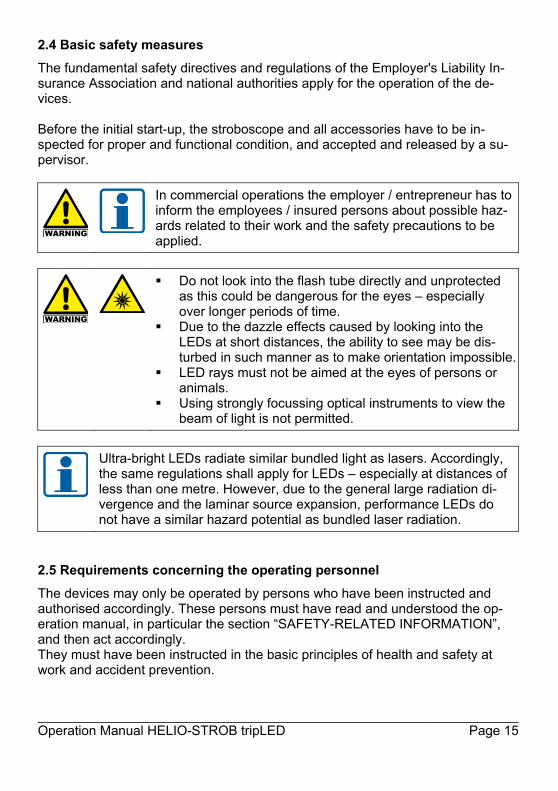
2.4 Basic safety measures The fundamental safety directives and regulations of the Employer's Liability In-surance Association and national authorities apply for the operation of the de-vices. Before the initial start-up, the stroboscope and all accessories have to be in-spected for proper and functional condition, and accepted and released by a su-pervisor.
In commercial operations the employer / entrepreneur has to inform the employees / insured persons about possible haz-ards related to their work and the safety precautions to be applied.
Do not look into the flash tube directly and unprotected as this could be dangerous for the eyes – especially over longer periods of time.
Due to the dazzle effects caused by looking into the LEDs at short distances, the ability to see may be dis-turbed in such manner as to make orientation impossible.
LED rays must not be aimed at the eyes of persons or animals.
Using strongly focussing optical instruments to view the beam of light is not permitted.
Ultra-bright LEDs radiate similar bundled light as lasers. Accordingly, the same regulations shall apply for LEDs – especially at distances of less than one metre. However, due to the general large radiation di-vergence and the laminar source expansion, performance LEDs do not have a similar hazard potential as bundled laser radiation.
2.5 Requirements concerning the operating personnel The devices may only be operated by persons who have been instructed and authorised accordingly. These persons must have read and understood the op-eration manual, in particular the section “SAFETY-RELATED INFORMATION”, and then act accordingly. They must have been instructed in the basic principles of health and safety at work and accident prevention.

Page 16 Operation Manual HELIO-STROB tripLED
2.6 Help with safety-related questions ELMED Dr. Ing. Mense GmbH Weilenburgstr. 39 D-42579 Heiligenhaus Germany Phone: +49 (0) 2056 / 9329 – 0 Fax: +49 (0) 2056 / 9329 – 33 E-Mail: [email protected] Web: www.elmedgmbh.de 2.7 Specific warnings
The persons listed below have to be informed of the hazards de-scribed in the following.
2.7.1 Wearers of active implants
Safety information for wearers of active implants When using stroboscopes, an influence on active implants (e.g. pacemakers) cannot be completely excluded. For safety reasons we recommend that people wearing active implants are excluded from working with stroboscopes. Persons wearing active implants have to be expressively instructed in this regard.
2.7.2 Epileptics
In case of users with a neurological proneness to epileptic sei-zures, the light effects produced by a stroboscope may cause photo-induced epilepsy. Users with such predisposition must not use strobo-scopes!

Operation Manual HELIO-STROB tripLED Page 17
3. TECHNICAL DATA / INPUTS & OUTPUTS
3.1 Technical data
Power supply 12.4 VDC (nominal voltage) Power consumption max. 14 W (without charging module) Dimensions of the case 182.5 x 117 x 117 mm³
(handle not included) Weight ca. 1.2 kg Light source 15 CREE high-performance LEDs Internal control of the flash rate twist knob and touch panel External control of the flash rate pos. impulses 5 to 30 V
(triggering edge individually adjustable) Signal propagation delay for external triggering
approx. 51 µs
Internal flash rate in Hz / fpm 1 - 840 Hz / 60 - 50400 fpm External flash rate in Hz / fpm 1 - 8000 Hz / 60 - 480000 fpm,
incoming flash rates > 845 Hz are split integrally.
Measurement duration 0.33 s (min. 1 period) Measuring value display LCD screen, height of digits 8.5 mm Display in fps / fpm Display resolution up to 0.01 Hz / 0.1 fpm Phase shifting in degree / ms Range degree / ms 0° - 540° / 0 - 999.99 ms Resolution degree / ms 0.1° / 0.001 - 0.01 ms Slow motion fps / fpm Resolution fps / fpm -5 fps - +5 fps / -300 fpm - +300 fpm Resolution slow motion 0.01 Hz / 0.1 fpm Variable transformation ratio (external triggering)
1:10 - 10:1
Resolution variable transformation ratio
0.001
Flash duration < 100 Hz: 1 - 100 µs (adjustable) > 100 Hz: 1 µs – max. 1 % of the period duration of the configured flash rate
Light output max. 0.17 Ws Light intensity max. 5500 Lux (distance: 50 cm) Accuracy 0.01 % ± 1 digit Operating temperature 0° ... +40° C Storage temperature -20° ... +50° C Air humidity 80% relative air humidity at 30° C

Page 18 Operation Manual HELIO-STROB tripLED
Power Supply – battery mode Battery type lithium-ion battery Output voltage 10.8 V Capacity 2900 mAh Charging cycles approx. 200 - 300 Battery life (performance-related) approx. 8 Std.
(at 50 Hz / 50 µs flash duration) Charging time approx. 3 hours
Mains unit / charger Input voltage 100 - 240 VAC / 50 - 60 Hz Output voltage 12.4 VDC 0 - 1.2 A
(without charging module) Operating temperature 0° C ... +40° C Storage temperature -20° C ... +50° C Dimensions 105 x 82 x 42 (mm) Weight approx. 200 g
3.2 Inputs / Outputs 3.2.1 Connector pin assignment POWER jack
Jack Pin Description
1 2 3 4 5 6 7
BATT - NTC BATT + nc AUX + AUX – nc
3.2.2 Connector pin assignment IN/OUT jack
Jack Pin Description
1 2 3 4 5
0 V (ground) +5 VDC (output) +12 VDC (output) Trigger OUT Trigger IN

Operation Manual HELIO-STROB tripLED Page 19
3.2.3 Trigger output
The HELIO STROB tripLED is equipped with a trigger output (Trigger OUT), for example to control other devices. The signal on the IN/OUT jack depends on the TTL level. The period duration depends on the flash rate; TLOW is constant (200 µs). If the stroboscope is controlled by an external signal, the output frequency corresponds to the input frequency up to 845 Hz. For frequencies > 845 Hz up to 8000 Hz a signal that is divided in integer numbers is supplied to the trigger out-put. The undivided frequency of the external signal source is shown on the display. Signal sequence:

Page 20 Operation Manual HELIO-STROB tripLED
4. INTIAL STARTUP
4.1 General information for putting into operation
In order to avoid damage to the device or injuries during putting into operation, observing the following points is essential:
The initial startup may only be performed by qualified persons un-der observation of the operation manual and the safety informa-tion.
Switching on the device is only permitted after verifying that proper and safe operation is ensured.
If defects are found in the course of inspection, these have to be properly rectified prior to putting the device into operation. The device may only be put into operation after all noted defects have been recti-fied.
Do not use any parts that have been damaged!
4.2 Electrical initial startup
1 On / Off switch 2 Display / touch panel 3 USB jack 4 Twist knob 5 IN/OUT jack 6 POWER jack

Operation Manual HELIO-STROB tripLED Page 21
4.3 Operation
Battery operation Switch on the stroboscope. The last settings (frequency / revolution speed etc.) are automatically loaded. New devices are generally de-livered with a partly charged battery. Charge the battery for extended use. Mains operation: Switch off the stroboscope before connecting the mains unit / charger to the stroboscope (“POWER” jack). The mains unit / charger is connected to the mains voltage and the POWER jack on the stroboscope. Allowable input voltage 100 – 240 VAC. Verify that the mains voltage corresponds to the information on the type plate. Switch on the device. The last settings (frequency / revolution speed etc.) are automatically loaded.
4.4 Functions
Select the functions by touching the corresponding buttons on the touch panel. Active functions and options are shown inverted on the display. To enter or change a value in the top row (large numbers), use the twist knob or alternatively the numeric keypad following selec-tion on the touch panel (see below). Twist knob: Turning quickly results in changes in large increments, turning slowly results in changes in small increments. An additional value in smaller numbers is shown on the bottom row of the display – when adjusting the frequency for example, the current phase shift value is shown in addition.
Touch panel Twist knob
Touch Turn
- +

Page 22 Operation Manual HELIO-STROB tripLED
4.4.1 Buttons of the touch panel
Flash rate Phase shift
Slow motion Multiplier Transformation ratio
Duration (flash duration) Display in flashes per minute Display in flashes per second Display in milliseconds in “Phase” mode Display in degrees in “Phase” / “Duration” mode Display in microseconds in “Duration” mode
Show numeric keypad
Numeric keypad
Division ratio input Decimal point Leading sign, slow motion value Correct / delete Confirm input / accept determined frequencies Cancel Return to original frequency
Reduce multiplier Increase multiplier
Trigger mode selection: Internal status Trigger mode selection: External status, rising edge Trigger mode selection: External status, falling edge
Internal triggering External triggering, rising edge External triggering, falling edge
Battery operation / battery charge level Mains operation / battery charging Twist knob

Operation Manual HELIO-STROB tripLED Page 23
4.4.2 Adjusting the frequency
or
Selecting the flash rate mode Display in [fpm] - flashes per minute Display in [fps] - flashes per second
Adjust value fpm / fps Show numeric keypad
Direct input as decimal number fpm / fps
Decimal point Correct / delete Confirm input Cancel
To determine revolution speeds or frequencies, begin with the maxi-mum value (flashes) and slowly reduce the frequency until the test ob-ject being observed appears to stand still. ATTENTION: When starting with the lowest frequency, there is a risk of determining a low fre-quency. This is because the test object appears to stand still even at an integral fraction of (for example half) the frequency. For checking the determined value in the INTERNAL trigger mode use the function by means of which the flash rate can be multiplied in integer numbers:
- +

Page 24 Operation Manual HELIO-STROB tripLED
Verify and double the flash rate Factor to increase the flash rate (max. 10 times) Factor to reduce the flash rate
Return to original frequency Accept determined frequency
in the second row of the display indicates that you cannot fur-ther increase the frequency using the multiplier .

Operation Manual HELIO-STROB tripLED Page 25
4.4.3 Phase shift
or
Phase shift mode selection Display in degrees Display in milliseconds
Set value degrees / millisecond Show numeric keypad
Direct input as decimal number degrees / millisecond
Decimal point Correct / delete Confirm input Cancel
The phase shift causes a delay between the trigger signal and the flash. This makes it possible to observe specific movement states in case of periodic movements of the test object. With the setting in de-grees, the object being observed is always seen in the same position regardless of the revolution speed. If a delay in milliseconds is set, corresponding to a phase shift greater than 540°, a corresponding notice appears in the second line of the display alternating with the standard message (see illustration).
- +

Page 26 Operation Manual HELIO-STROB tripLED
4.4.4 Slow motion
or
Select slow motion mode Display in [fpm] - flashes per minute Display in [fps] - flashes per second
Adjust value fpm / fps Show numeric keypad
Direct input as decimal number fpm / fps
Decimal point Leading sign, slow motion value Correct / delete Confirm input Cancel
The entire periodic movement sequence of a test object can be ob-served with the help of slow motion. It creates the impression that the object is moving slowly and continuously. Select the speed and movement direction between +5 Hz and -5 Hz (beat frequency).
- +

Operation Manual HELIO-STROB tripLED Page 27
4.4.5 Transformation ratio
or
or
Select “Transformation Ratio” mode Set the ratio as a decimal number Show numeric keypad
Direct input of the ratio as a decimal number / ratio
Numeric input of the ratio Decimal point Correct / delete Confirm input Cancel
This function can only be activated with “external triggering”. The ratio between the flash and the trigger frequency can be entered in the range of 0.100 to 10.00 (decimal) or as a ratio (such as 3:4). With the “Transformation Ratio” function it is for example possible to use the trigger signal of a transducer on the motor axis in order to ob-tain a still image of a shaft connected via a transmission.
- +

Page 28 Operation Manual HELIO-STROB tripLED
Notes on entering the “transformation ratio”
Exceeding the allowable range of 0.100 to 10.00
Falling below the allowable range of 0.100 to 10.00
If the entered ratio exceeds or falls below the allowable range of 0.100 to 10.00, a corresponding message is shown on the display for 4 sec-onds. The smallest possible ratio (0.100) is automatically set if the value is too low, and the largest possible ratio (10.00) is set if the value is too high.
If the flash rate resulting from the configured ratio falls below the allowable range (< 1 Hz), a “<” char-acter is shown before the frequency. If the resulting flash rate exceeds the allowable range (> 845 Hz), there is no warning and the fre-quency is automatically divided integrally.
4.4.6 Triggering
Supplying the external trigger signal via the IN / OUT jack. If no exter-nal trigger signal is applied or the frequency of the external trigger source is less than 1 Hz in “external triggering” mode, the display shows “-.--”. With external signals > 0 Hz, the stroboscope flashes at the external clock. Frequencies > 845 Hz to 8000 Hz are integrally di-vided. The undivided frequency of the external clock is shown on the display.

Operation Manual HELIO-STROB tripLED Page 29
4.4.6.1 Internal triggering
Select the triggering mode Select the option “Internal Triggering”
Confirm input 4.4.6.2 External triggering, rising edge
Select the triggering mode Select the option “External triggering, rising edge”
Confirm input 4.4.6.3 External triggering, falling edge
Select the triggering mode Select the option “External triggering, falling edge”
Confirm input

Page 30 Operation Manual HELIO-STROB tripLED
4.4.7 Flash duration (button “Duration”)
The LED technology offers the opportunity to vary the flash duration (the on-time of the light source), either in “µs” (microseconds) or in “ ° ” (degrees). Hereby the following features can be varied: the contour sharpness of a test object
and simultaneously the output brightness of the device A shorter flash duration improves the contour sharpness. At the same time, the brightness decreases. Depending on the application, the op-timum combination of contour sharpness and brightness can be found. With the setting in “ ° ” (degrees), the flash duration changes depend-ing on the flash rate. The ratio of the flash duration to the period dura-tion remains constant. If the option “µs” (microsecond) is chosen, it stays the same length for any flash rate (within limits). This means a maximum flash duration of 100 microseconds can be set up to 100 Hz. The flash duration can also be set to max 1 % of the period duration for the currently selected flash rate. Since the two modes work independently of each other, the active (se-lected) mode is shown inverted.
0 6000 12000 18000 24000 30000 36000 42000 48000
0
20
40
60
80
100
120
0 100 200 300 400 500 600 700 800
Speed / min-1
Flas
h du
ratio
n / µ
s
Frequency / Hz
Max. flash duration depending on the frequency

Operation Manual HELIO-STROB tripLED Page 31
4.4.7.1 Flash duration, degrees
Select Duration mode (flash duration)
Select the option “Degrees” Set value Confirm input
4.4.7.2 Flash duration, microsecond
Select Duration mode (flash duration) Select the option “Microsecond”
Set value Confirm input
- +
- +

Page 32 Operation Manual HELIO-STROB tripLED
4.5 Touch panel calibration
Recalibration of the touch panel may be necessary, e.g. due to ageing of the panel or failure to recognise contact. To calibrate the touch panel, please pro-ceed as follows:
After turning on the stroboscope, touch the home screen on the dis-play for about 5 seconds.
Touch the cross that ap-pears in the bottom left corner.
Touch the cross that ap-pears in the upper right corner. Finished!
4.6 Serial interface Via the serial interface, the HELIO-STROB tripLED can be computer-controlled. It is also possible to update the firmware via the serial interface. Further information on controlling via PC and firmware updating can be found on our Internet service page. URL: http://support.elmed.eu/helio/ Username: helio Password: 8yBMJoDQ

Operation Manual HELIO-STROB tripLED Page 33
4.7 Power supply
The HELIO-STROB tripLED is equipped with a lithium-ion battery. The required charging technology is integrated in the supplied mains unit / charger. Therefore the supplied mains unit / charger cannot be replaced by a conventional mains adapter!
4.7.1 Battery operation The HELIO-STROB tripLED is equipped with a long-life lithium-ion battery. The battery operating time depends on the configured flash rate and duration. At a flash rate of 50 Hz and a flash duration of 50 µs, the HELIO-STROB tripLED can be operated on battery for approximately 8 hours. Continuing to use the strobo-scope is possible even when the battery is drained. In order to do so, the supplied mains unit / charger is connected to the mains network and to the POWER jack on the stroboscope. 4.7.2 Mains operation With the mains unit / charger included in the scope of delivery, the HELIO-STROB tripLED can be operated using mains voltage. The mains unit / charger is con-nected to the mains voltage and the POWER jack on the stroboscope. Allowable input voltage 100 – 240 VAC. Verify that the mains voltage corresponds to the in-formation on the type plate. During mains operation of the stroboscope, the bat-tery is charged in parallel. 4.7.2.1 Charging the battery To charge the battery, the supplied mains unit / charger is connected to the mains network and to the POWER jack on the stroboscope. Allowable input voltage 100 – 240 VAC. Verify that the mains voltage corresponds to the information on the type plate. The green charging indicator on the mains unit / charger flashes during the charg-ing process and lights up continuously once the battery is fully charged. It takes approximately 3 hours to charge a fully drained battery. When the stroboscope is on, the battery charge level is also shown on the display.

Page 34 Operation Manual HELIO-STROB tripLED
4.7.2.2 Replacing the battery The battery has to be replaced by the manufacturer or by trained, electrically skilled persons authorised by the manufacturer. Only batteries specified by the manufacturer may be used as replacements.
Using non-specified batteries is associated with the following hazards: Electrical hazard Fire hazard Explosion hazard
Used batteries have to be disposed of according to the applicable le-gal regulations.

Operation Manual HELIO-STROB tripLED Page 35
5. MAINTENANCE
5.1 Maintenance
According to the design, the HELIO-STROB tripLED is not susceptible to distur-bance. However, the following should be generally observed: Do not throw the device or expose it to heavy impacts. Store the device protected from damage. Clean the device using only a soft, slightly moist cloth.
Use only mild detergents. Maintenance schedule
Bef
ore
putti
ng in
to o
pera
tion
Dai
ly
Wee
kly
Mon
thly
Ann
ually
As
need
ed
Inspect the HELIO-STROB tripLED for mechanical damage X X
Inspect the mains unit / charger for mechanical damage X X
Safety inspection X X
The time intervals specified in the maintenance plan are guidelines. The intervals have to be established by the customer and verified depending on the operating conditions.

Page 36 Operation Manual HELIO-STROB tripLED
5.2 Inspection / Calibration To maintain the reliability and the high quality standard of the HELIO-STROB tripLED over a long period of time, the device should be inspected by the manu-facturer on a regular basis. All device-specific functions are checked in the course of maintenance. A PTB-traceable (Physiaklisch-Technische Bundesanstalt, the German Bureau fo Standards) manufacturer certificate is issued by request. The result of maintenance work is documented in an inspection record and stored in a product database. 5.3 Repairs Devices that are damaged or do not perform according to their specifications shall not be used any more. To provide a safe and functional device, only original spare parts shall be used for repair.
To dispose of the old device according to legal rules and provisions, please send the HELIO-STROB tripLED to the manufacturer.
For maintenance / repair or disposal, please send the HELIO-STROB tripLED free to the door addressed to: ELMED Dr. Ing. Mense GmbH Stroboscope Service Weilenburgstr. 39 D-42579 Heiligenhaus GERMANY
Proper execution of maintenance and repair is guaranteed only by the manufacturer or by qualified and authorised service centres.

Operation Manual HELIO-STROB tripLED Page 37
5.4 Replacement parts / Accessories
Item no. Designation
0365100052 Handle
0310610050 5-pin plug (triggering IN / OUT)
0310210012 Mains unit / charger for HELIO-STROB tripLED
0310210180 Replacement battery for HELIO-STROB tripLED
0310200070 USB connection cable, A/St – B/St, length 1.8 m
0310550020 Transport box

Page 38 Operation Manual HELIO-STROB tripLED
6. DRAWINGS
6.1 Markings on the housing

Operation Manual HELIO-STROB tripLED Page 39
7. OPERATION MANUAL FOR MAINS UNIT / CHARGER
Read instruction manual before use! Operation manual for mains unit / charger EGSTON C2CFMW3 24W for lithium-ion batteries 7.1 Introduction The mains unit / charger complies with the latest state-of-the-art technology. It is safety and EMC tested and is therefore in accordance with the valid International, European and National guidelines. The conformity has been proven; the relevant documentation is being kept at the manufacturer. In order to maintain this condi-tion and to guarantee a safe use, you as a user have to pay attention to this man-ual! If you have any questions, please contact the manufacturer. The switched mode EGSTON mains unit / charger is microprocessor controlled and programmed to work with the HELIO-STROB tripLED. 7.2 Safety-related information
7.2.1 Safety symbols and their meaning Safety symbols impart safety information through a combination of: geometric shape colour graphical symbol / text They are used both on the device and in the operation manual to point out situa-tions with a possible hazard potential quickly and clearly. All safety-related passages in this operation manual are highlighted with one of the following safety symbols. Provide all persons working with the device with the safety information. Special symbols indicate important information that must be strictly observed.

Page 40 Operation Manual HELIO-STROB tripLED
The following symbols are used in this operation manual:
This symbol indicates a hazardous situation which, if it is not avoided, can lead to serious injuries or death.
This symbol indicates a warning of hazardous electrical voltage.
This symbol indicates important information in the operation manual that must be strictly observed.
This symbol indicates information provided for improving the under-standing of processes.
7.2.2 Safety instructions
To ensure safe operation, the user must observe all safety instructions and warn-ings contained in this operation manual.
No liability is assumed for material or personal damage caused by in-appropriate use or non-adherence to the safety instructions. In such cases any warranty claim is invalid.
Before use please check if the mains voltage is in accordance with the voltage stated on the Egston mains unit / charger.
Warming of the housing during operation is normal and harmless. While in operation the charger must not be covered or operated near radiators or in direct sun light.

Operation Manual HELIO-STROB tripLED Page 41
The mains unit / charger must only be used with the HELIO-STROB tripLED.
The Egston mains unit / charger is intended to be used correctly oriented in a vertical of floor mount position.
Operation is permitted only on sockets approved for max. 16 A.
Protect against water. The equipment should be installed close to an easily ac-
cessible power outlet. For indoor use only.
This device conforms to safety class II. Please make sure that the insulation (of the housing and the output cable respectively) is neither damaged nor destroyed. The regulations for safety against accident valid at the time must be adhered to.
Explosive gases can develop while charging. Take care for sufficient ventilation when charging batteries. Avoid spark formation and other sources of ignition near the battery. The charger must not be covered during the charging process.
The unit may not be used by persons with limited physical, sensory or mental ca-pabilities or persons with lack of experience and knowledge unless proper super-vision or instruction for the safe use and resulting dangers is given. The mains unit / charger must only be stored and used out of reach of unauthor-ized persons. Use the mains unit / charger only when the housing is closed safely and screwed tightly.
Avoid operation under adverse environmental conditions. These will lead to damage of the sensitive electronics inside the charger thereby causing possible danger to the user. Adverse environmental conditions are: high humidity level
(> 95% relative humidity, condensing) moisture dust and flammable gases, vapours or solvents, gasoline fuel excessive ambient temperatures (> +40° C, > +104° F)

Page 42 Operation Manual HELIO-STROB tripLED
When operating a charger inappropriately (excessive charging currents or wrong polarity) the battery can be over-charged or destroyed. In the worst case the battery can explode thus causing considerable damage.
Keep radio transmitters (wireless phones, remote control transmitters for model toys) away from the mains unit / charger because the radio emissions can interfere with the charging cycle and lead to the destruction of the charger and/or to the destruction of the batteries.
The electrical conducting parts of the connected user device are to be pro-tected against direct contact.
If it has to be assumed that safe operation is no longer possible, the device must be taken out of operation and protected against involuntary use. It can be assumed that safe operation is no longer possible when the device shows visible damage or the device no longer operates.
Never connect the mains unit / charger immediately to the mains when it has been brought from a cold to a warm room. Under adverse conditions the con-densing water can destroy the device. For that reason the mains unit / charger must heat up for at least 3 hours in the warm room before being con-nected to the mains.
Take care for sufficient ventilation when charging batteries due to the possible creation of hydrogen gas. Never expose to open fire or flying sparks.
It is normal that the batteries become warm when charging. By improper use (wrong polarity etc.) the battery can be over-
charged (too hot) and will be destroyed. In the worst case the bat-tery can explode and cause considerable damage.
Please take care that defective / not chargeable and used up (old) batteries are hazardous waste material and that these must be disposed of according to national regulations.
Please always consider the safety instructions.

Operation Manual HELIO-STROB tripLED Page 43
7.3 Connection / Operation / Charging
Under no circumstances connect batteries other than the built-in bat-tery of the HELIO-STROB tripLED to the Egston mains unit / charger. The Egston mains unit /charger is programmed according to the spe-cial requirements of the batteries of the HELIO-STROB tripLED. When charging other battery types, these batteries can be destroyed, overheat or in worst case explode.
The connection must only be made to the original polarized output connector
mounted on the Egston mains unit / charger. First connect the Egston mains unit / charger to a mains socket
(100 – 240 VAC, 50 – 60 Hz). Then connect the polarized connecting cable with the HELIO-STROB
tripLED. The charging begins immediately, visibly at the display at the top side of the
Egston mains unit / charger. The automatic mains supply starts when the HELIO-STROB tripLED is switched on. At the same time the built-in battery is charged.
If the display is not lit, the contacts are possibly oxidised, the connecting ca-ble is interrupted or damaged, the battery is damaged or the mains supply is interrupted.
The charging time depends on environmental temperature, the condition of the battery, the charging status of the battery etc. The device switches off automatically.
If the mains unit / charger is disconnected from the mains, the battery must also be disconnected.
7.3.1 Operating display
Rapid Charge LED flashes green
Charge Complete LED lights up in green
Precharge slow charging - LED flashes orange
Charge Pending no charging since battery temperature is too low / high LED lights up in orange
Charge Failure error in power pack - LED lights up in red
No AC no input voltage on mains unit / charger (INPUT) LED does not light

Page 44 Operation Manual HELIO-STROB tripLED
7.4 Maintenance The Egston mains unit / charger is maintenance-free. Under no circumstances may the device be opened or modified. All warranty claims expire on opening or disassembling the mains unit /
charger. For cleaning use a clean, dry, antistatic and fuss free cleaning cloth. The contacts of the mains unit / charger must always be kept clean. 7.5 Waste disposal
Dispose of the irreparable mains unit / charger according to the appli-cable legal regulations.
7.6 Technical data INPUT: 100 – 240 V ~ / 50 – 60 Hz / 550 mA OUTPUT: 12.4 V /1.2 A
Jack Pin Description
1 2 3 4 5 6 7
BATT - NTC BATT + nc AUX + AUX – nc

Operation Manual HELIO-STROB tripLED Page 45
7.7 Description of symbols
EU conformity mark with EU directive 93/42/EEC
WEEE: This product must not be disposed of with normal domestic waste
Caution: Follow the operating instructions
Protection class II
000
or
NRTL mark for USA and Canada
7.8 Final information This operation manual conforms the current technical specification at the time of printing. Revisions in the course of technical progress reserved. Manufacturer of the mains unit / charger: EGSTON System Electronics Eggenburg GmbH Grafenbergerstr. 37 A-3730 Eggenburg Austria © Copyright 2016 by Egston GmbH Version: April 2016

Page 46 Operation Manual HELIO-STROB tripLED
_________________________________________________________________ _________________________________________________________________ _________________________________________________________________ _________________________________________________________________ _________________________________________________________________ _________________________________________________________________ _________________________________________________________________ _________________________________________________________________ _________________________________________________________________ _________________________________________________________________ _________________________________________________________________ _________________________________________________________________ _________________________________________________________________ _________________________________________________________________ _________________________________________________________________ _________________________________________________________________ _________________________________________________________________ _________________________________________________________________ _________________________________________________________________ _________________________________________________________________ _________________________________________________________________ _________________________________________________________________

Operation Manual HELIO-STROB tripLED Page 47
_________________________________________________________________ _________________________________________________________________ _________________________________________________________________ _________________________________________________________________ _________________________________________________________________ _________________________________________________________________ _________________________________________________________________ _________________________________________________________________ _________________________________________________________________ _________________________________________________________________ _________________________________________________________________ _________________________________________________________________ _________________________________________________________________ _________________________________________________________________ _________________________________________________________________ _________________________________________________________________ _________________________________________________________________ _________________________________________________________________ _________________________________________________________________ _________________________________________________________________ _________________________________________________________________ _________________________________________________________________

Page 48 Operation Manual HELIO-STROB tripLED
_________________________________________________________________ _________________________________________________________________ _________________________________________________________________ _________________________________________________________________ _________________________________________________________________ _________________________________________________________________ _________________________________________________________________ _________________________________________________________________ _________________________________________________________________ _________________________________________________________________ _________________________________________________________________ _________________________________________________________________ _________________________________________________________________ _________________________________________________________________ _________________________________________________________________ _________________________________________________________________ _________________________________________________________________ _________________________________________________________________ _________________________________________________________________ _________________________________________________________________ _________________________________________________________________ _________________________________________________________________