operation manual helio-strob alpha / beta / beta … · page 2 operation manual helio-strob alpha,...
TRANSCRIPT
Operation Manual HELIO-STROB ALPHA, BETA, BETA A2 Page 1
CONTENTS Product Description 2 1. Proper use 2 2. Scope of supply / Design 3 2.1 Scope of supply 3 2.2 Design 3 2.3 Operation instructions 4 2.3.1 Controls – front panel ALPHA 4 2.3.2 Controls – front panel BETA / BATA A2 4 2.3.3 Controls – rear panel 4 2.3.4 Controls – hand-held lamp 5 3. Functional description 6 4. Technical data 7 5. General features 8 EC Declaration of Conformity 9 General Safety Instructions 10 1. Explanation of safety symbols used in this manual 10 2. User’s due diligence 11 3. Special hazards 12 4. Basic rules on safety precautions 12 5. Basic safety measures 13 6. Requirements concerning the operating personnel 14 Initial startup 14 1. General steps to take when starting up 14 2. Funktional description 16 2.1 Adjusting the frequency / speed (internal clock) 16 2.2.1 Adjusting the phase shift (standard) 17 2.2.2 Adjusting the phase shift together with slow motion (optional) 17 2.2.3 Slow Motion (optional) 18 2.3 Control by external clock 19 2.4 Mains synchronous triggering 20 2.5 Flank 20 2.6 Power control - dimmer 21 2.7 Trigger output 21 Maintenance 22 1. Storage 22 2. Maintenance 22 3. Inspection / Calibration 22 4. Repairs / Disposal 22 Additional Information 24 1. Pin assignments 24 1.1 Socket assignments “external clock” 24 1.2 Hand-held lamp socket 24 2. Problems and remedies 25 3. Replacing the flash tube 27
V. 03/2013
Page 2 Operation Manual HELIO-STROB ALPHA, BETA, BETA A2
Product Description
1. Proper use
The HELIO-STROB is a stroboscope (light flashing instrument) for indus-trial applications. This instrument is used to produce snapshots of se-quences which, due to the rapidity with which they proceed, are not per-ceivable by the human eye.
Please note that operating the instrument in explosion hazard-ous environment is strictly forbidden.
Appropriate use also includes reading and understanding these operating instructions and complying with the information given in them, especially the safety information. This also includes carrying out all the inspection and maintenance work at the specified intervals. The operation of stroboscopes may cause failure or interferences of nearby radio devices or radio service. In this case, suspend the operation of the instrument. As a basic principle, keep the operation of the instrument as short as possible. To avoid personal injury or damage to the equipment, only qualified, trained and authorised personnel should operate the HELIO-STROB. Safe operation cannot be assured if the HELIO-STROB is not used in ac-cordance with the above definition of appropriate use. The user, not the producer, shall assume any liability related to any per-sonal injury or material damage resulted from the inadequate use of the in-strument.
Operation Manual HELIO-STROB ALPHA, BETA, BETA A2 Page 3
2. Scope of supply / Design
2.1 Scope of supply
The standard scope of supply consists of the following components: Control unit Hand-held lamp incl. flash tube and connecting cable Allen wrench 2.5 mm Power connecting cable Operation manual Please check if the scope of supply is complete!
2.2 Design
The instruments are designed and manufactured according to acknow-ledged safety rules and the current state of the art. The basic design of HELIO-STROB consists of the following components: Case (control unit) Rugged aluminum case with adjustable unit
handle Case (hand-held lamp) Metal case with tripod connector and unit
handle Power supply 110V / 230V 50-60 Hz, adjustable by voltage
selector Operation Function keys and adjusting knob Display Five-digit seven-segment display Connection control unit / hand-held lamp
Cable length 2m (standard) Cable connections (pluggable)
Signal input / output Diode female connector
To avoid personal injury and damage to the equipment, re-pairs must be performed only by professionally trained tech-nicians authorised by ELMED. Take special care when opening the device and/or the hand lamp, since it is then possible to touch parts carrying a volt-age that is considerably higher than the supply voltage.
Page 4 Operation Manual HELIO-STROB ALPHA, BETA, BETA A2
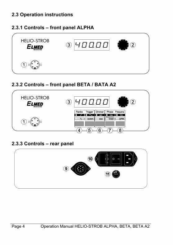
2.3 Operation instructions
2.3.1 Controls – front panel ALPHA
HELIO-STROB
2.3.2 Controls – front panel BETA / BATA A2
Slowmotion
HELIO-STROB
2.3.3 Controls – rear panel
9
10
11
Operation Manual HELIO-STROB ALPHA, BETA, BETA A2 Page 5
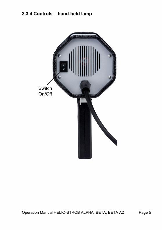
2.3.4 Controls – hand-held lamp
Page 6 Operation Manual HELIO-STROB ALPHA, BETA, BETA A2
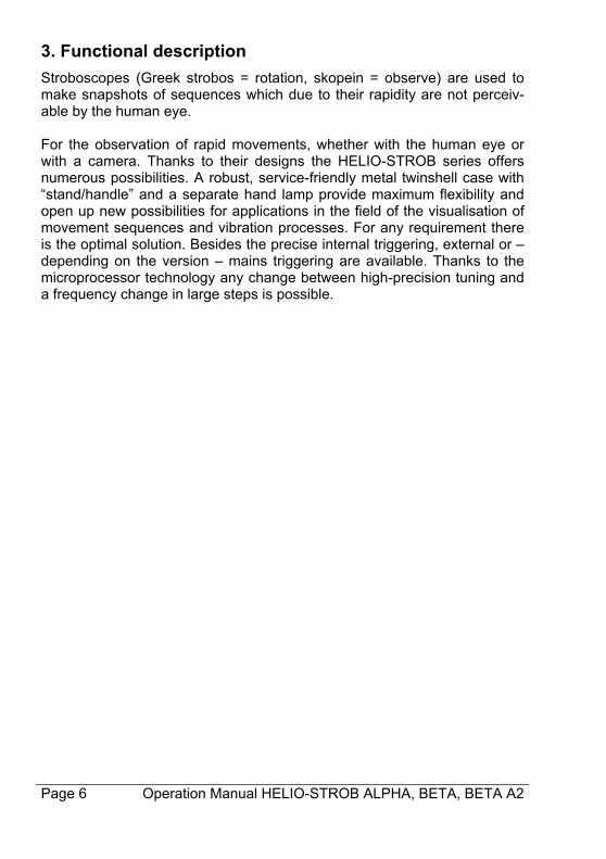
3. Functional description
Stroboscopes (Greek strobos = rotation, skopein = observe) are used to make snapshots of sequences which due to their rapidity are not perceiv-able by the human eye. For the observation of rapid movements, whether with the human eye or with a camera. Thanks to their designs the HELIO-STROB series offers numerous possibilities. A robust, service-friendly metal twinshell case with “stand/handle” and a separate hand lamp provide maximum flexibility and open up new possibilities for applications in the field of the visualisation of movement sequences and vibration processes. For any requirement there is the optimal solution. Besides the precise internal triggering, external or – depending on the version – mains triggering are available. Thanks to the microprocessor technology any change between high-precision tuning and a frequency change in large steps is possible.
Operation Manual HELIO-STROB ALPHA, BETA, BETA A2 Page 7
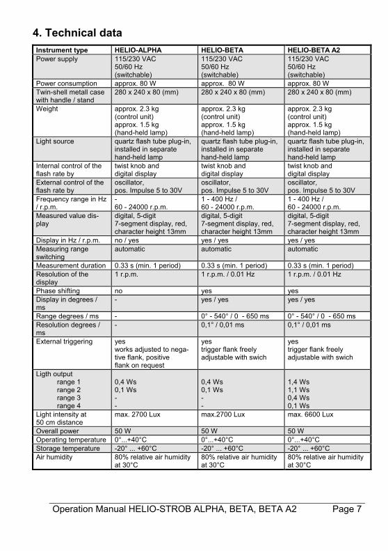
4. Technical data
Instrument type HELIO-ALPHA HELIO-BETA HELIO-BETA A2 Power supply 115/230 VAC
50/60 Hz (switchable)
115/230 VAC 50/60 Hz (switchable)
115/230 VAC 50/60 Hz (switchable)
Power consumption approx. 80 W approx. 80 W approx. 80 W Twin-shell metall case with handle / stand
280 x 240 x 80 (mm) 280 x 240 x 80 (mm) 280 x 240 x 80 (mm)
Weight approx. 2.3 kg (control unit) approx. 1.5 kg (hand-held lamp)
approx. 2.3 kg (control unit) approx. 1.5 kg (hand-held lamp)
approx. 2.3 kg (control unit) approx. 1.5 kg (hand-held lamp)
Light source quartz flash tube plug-in, installed in separate hand-held lamp
quartz flash tube plug-in, installed in separate hand-held lamp
quartz flash tube plug-in, installed in separate hand-held lamp
Internal control of the flash rate by
twist knob and digital display
twist knob and digital display
twist knob and digital display
External control of the flash rate by
oscillator, pos. Impulse 5 to 30V
oscillator, pos. Impulse 5 to 30V
oscillator, pos. Impulse 5 to 30V
Frequency range in Hz / r.p.m.
- 60 - 24000 r.p.m.
1 - 400 Hz / 60 - 24000 r.p.m.
1 - 400 Hz / 60 - 24000 r.p.m.
Measured value dis-play
digital, 5-digit 7-segment display, red, character height 13mm
digital, 5-digit 7-segment display, red, character height 13mm
digital, 5-digit 7-segment display, red, character height 13mm
Display in Hz / r.p.m. no / yes yes / yes yes / yes Measuring range switching
automatic automatic automatic
Measurement duration 0.33 s (min. 1 period) 0.33 s (min. 1 period) 0.33 s (min. 1 period) Resolution of the display
1 r.p.m. 1 r.p.m. / 0.01 Hz 1 r.p.m. / 0.01 Hz
Phase shifting no yes yes Display in degrees / ms
- yes / yes yes / yes
Range degrees / ms - 0° - 540° / 0 - 650 ms 0° - 540° / 0 - 650 ms Resolution degrees / ms
- 0,1° / 0,01 ms 0,1° / 0,01 ms
External triggering yes works adjusted to nega-tive flank, positive flank on request
yes trigger flank freely adjustable with swich
yes trigger flank freely adjustable with swich
Ligth output range 1 range 2 range 3 range 4
0,4 Ws 0,1 Ws - -
0,4 Ws 0,1 Ws - -
1,4 Ws 1,1 Ws 0,4 Ws 0,1 Ws
Light intensity at 50 cm distance
max. 2700 Lux max.2700 Lux max. 6600 Lux
Overall power 50 W 50 W 50 W Operating temperature 0°...+40°C 0°...+40°C 0°...+40°C Storage temperature -20° ... +60°C -20° ... +60°C -20° ... +60°C Air humidity 80% relative air humidity
at 30°C 80% relative air humidity at 30°C
80% relative air humidity at 30°C
Page 8 Operation Manual HELIO-STROB ALPHA, BETA, BETA A2
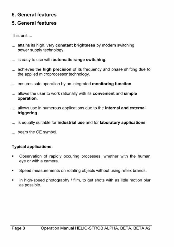
5. General features
5. General features
This unit ... ... attains its high, very constant brightness by modern switching power supply technology. ... is easy to use with automatic range switching. ... achieves the high precision of its frequency and phase shifting due to
the applied microprocessor technology. ... ensures safe operation by an integrated monitoring function. ... allows the user to work rationally with its convenient and simple
operation. ... allows use in numerous applications due to the internal and external triggering. ... is equally suitable for industrial use and for laboratory applications. ... bears the CE symbol. Typical applications: Observation of rapidly occuring processes, whether with the human
eye or with a camera. Speed measurements on rotating objects without using reflex brands. In high-speed photography / film, to get shots with as little motion blur
as possible.
Operation Manual HELIO-STROB ALPHA, BETA, BETA A2 Page 9
EC Declaration of Conformity It is herewith confirmed that the product listed below
HELIO-STROB ALPHA, BETA, BETA A2 meets the safety requirements within the scope of the conformity evaluation procedure of the related competent authority, which are defined in the regulation 2004/108/EG of the European Council for the approximation of laws of the member states with respect to electromagnetic compatibility. The same applies to the provisions of the law on electromagnetic compati-bility of instruments (EMVG) as of 9 November 1992. This declaration ap-plies to all units that are manufactured in accordance with the appropriate manufacturing documentation which is part of this declaration. For the evaluation of products regarding the electromagnetic compatibility relevant harmonised standards have been used. DIN EN 61000-6-1 DIN EN 61000-6-3 Design-engineering modifications that have such significant effects on the technical specifications and the proper use defined in this operation manual so as to change the instrument considerably shall nullify this declaration of conformity. This declaration shall be legally binding for the manufacturer. ELMED Dr. Ing. Mense GmbH, Heiligenhaus signed by
Claudia Mense Managing Director Heiligenhaus, 11.10.2011
Page 10 Operation Manual HELIO-STROB ALPHA, BETA, BETA A2
General Safety Instructions 1. Explanation of safety symbols used in this manual
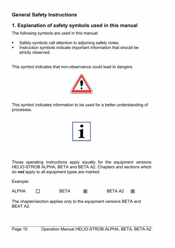
The following symbols are used in this manual: Safety symbols call attention to adjoining safety notes. Instruction symbols indicate important information that should be
strictly observed. This symbol indicates that non-observance could lead to dangers.
This symbol indicates information to be used for a better understanding of processes.
These operating instructions apply equally for the equipment versions HELIO-STROB ALPHA, BETA and BETA A2. Chapters and sections which do not apply to all equipment types are marked. Example: ALPHA BETA BETA A2 The chapter/section applies only to the equipment versions BETA and BEAT A2.
Operation Manual HELIO-STROB ALPHA, BETA, BETA A2 Page 11
2. User’s due diligence
The HELIO-STROB has been developed and manufactured in considera-tion of hazard analyses and in compliance with the relevant harmonized standards as well as the additional technical specifications. Therefore, the HELIO-STROB is a state-of-the-art instrument and offers a maximum of safety. This safety can be achieved only if all required safety precautions have been taken. Subject to due diligence, the user of this instrument shall plan such precautions and supervise their execution. The user shall particularly ensure that the HELIO-STROB is used properly (see chapter Product description) the instruments are operated only if in perfect, fully functional condition the complete operation instructions are legible and available at the
place where the instrument is used. the instruments are operated only by adequately qualified and author-
ised personnel which is regularly trained in all aspects related to occu-pational health and safety; this personnel knows and follows the opera-tion instructions, especially the relevant safety regulations contained therein.
all safety and warning labels are clearly legible and none of them are removed from the instrument.
Page 12 Operation Manual HELIO-STROB ALPHA, BETA, BETA A2
3. Special hazards
In case of users with a neurological proneness to epilep-tic seizures, the light effects produced by a stroboscope may cause photo induced epilepsy. Users with such predisposition must not use stroboscopes!
Safety precautions for persons with active implants When using a stroboscope an influence on active implants (e.g. pacemakers) cannot be excluded with certainty. For safety reasons we recommend to exclude users with active implants from working with a stroboscope. Persons with active implants are to be instructed in this regard.
4. Basic rules on safety precautions
Within professional organizations the employer / entrepreneur has to inform the employees / insured workers about the pos-sible hazards related to their work and the safety precautions to be applied. This shall include the current findings regarding hazard avoiding procedures and eyelid protective reflexes.
Do not look into the flash tube directly and unprotected as this could be
dangerous for the eyes – especially over longer periods of time. Due to dazzle effects caused by the flashlight at short distances, the
ability to see may be disturbed in such manner as to make orientation impossible.
Flashlights shall not be directed to the eyes of other persons.
Operation Manual HELIO-STROB ALPHA, BETA, BETA A2 Page 13
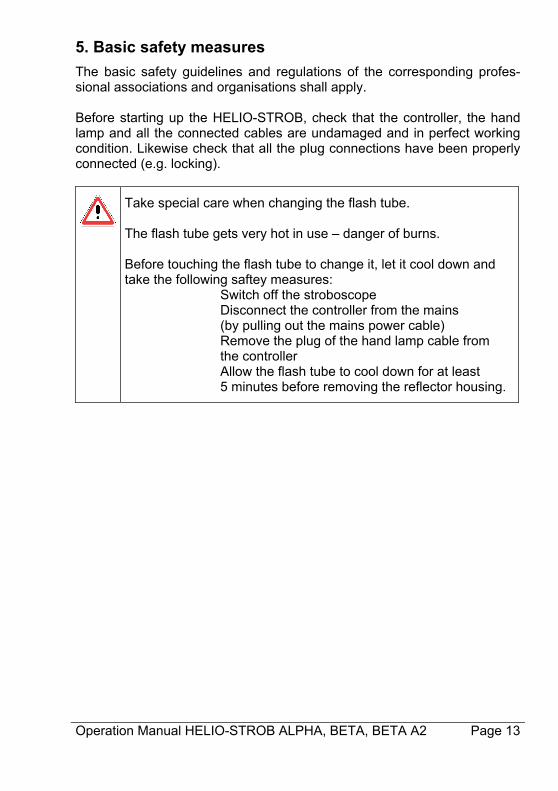
5. Basic safety measures
The basic safety guidelines and regulations of the corresponding profes-sional associations and organisations shall apply. Before starting up the HELIO-STROB, check that the controller, the hand lamp and all the connected cables are undamaged and in perfect working condition. Likewise check that all the plug connections have been properly connected (e.g. locking).
Take special care when changing the flash tube. The flash tube gets very hot in use – danger of burns. Before touching the flash tube to change it, let it cool down and take the following saftey measures:
Switch off the stroboscope Disconnect the controller from the mains
(by pulling out the mains power cable) Remove the plug of the hand lamp cable from
the controller Allow the flash tube to cool down for at least 5 minutes before removing the reflector housing.
Page 14 Operation Manual HELIO-STROB ALPHA, BETA, BETA A2
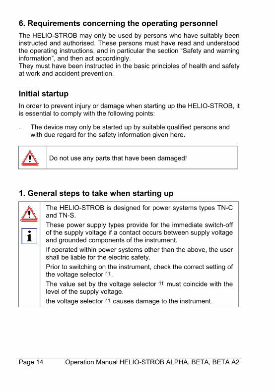
6. Requirements concerning the operating personnel
The HELIO-STROB may only be used by persons who have suitably been instructed and authorised. These persons must have read and understood the operating instructions, and in particular the section “Safety and warning information”, and then act accordingly. They must have been instructed in the basic principles of health and safety at work and accident prevention.
Initial startup
In order to prevent injury or damage when starting up the HELIO-STROB, it is essential to comply with the following points: - The device may only be started up by suitable qualified persons and
with due regard for the safety information given here.
Do not use any parts that have been damaged!
1. General steps to take when starting up
The HELIO-STROB is designed for power systems types TN-C and TN-S.
These power supply types provide for the immediate switch-off of the supply voltage if a contact occurs between supply voltage and grounded components of the instrument.
If operated within power systems other than the above, the user shall be liable for the electric safety.
Prior to switching on the instrument, check the correct setting of the voltage selector 11 .
The value set by the voltage selector 11 must coincide with the level of the supply voltage.
the voltage selector 11 causes damage to the instrument.
Operation Manual HELIO-STROB ALPHA, BETA, BETA A2 Page 15
Connect the hand lamp and the control unit. Plug in the plug of the hand lamp cable into the corresponding socket 12 at the front of the control unit and then lock it in place. Turn the switch for the hand lamp so that it is ready for operation.
Connect the control unit to the mains power. Plug in the plug of the mains cable into the corresponding socket at the back of the control unit and connect the earthing contact plug of the mains cable to the mains socket.
Switch on the device at the mains switch at the back of the control
unit. After performing a short self-test the unit loads the last values that were set for frequency / r.p.m., phase angle, etc. The current settings can be read from the display and the LEDs. The HELIO-STROB is now ready for operation.
By pressing the switch on the back panel of the hand lamp the flash frequency is activated or interrupted.
In order to protect the hand lamp from thermal destruction, the flash generation is automatically interrupted at the maximum operating temperature. After a cooling period the hand lamp switches on automatically.
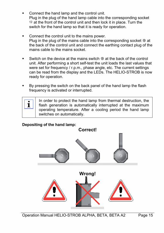
Depositing of the hand lamp:
Correct!
Wrong!
Page 16 Operation Manual HELIO-STROB ALPHA, BETA, BETA A2
2. Funktional description
2.1 Adjusting the frequency / speed (internal clock)
ALPHA BETA BETA A2 “Internal operation“ is indicated on the display by the steadily lit decimal point. The desired frequency / speed can be adjusted with the twist knob . The internal microprocessor controls the function of the twist knob ac-cording to the speed of rotation: rapid rotation: rapid change in large steps
slow rotation: fine adjustment in small steps ALPHA BETA BETA A2 “Internal operation“ is indicated on the display by the steadily lit decimal point. This mode is selected by pressing the key . Pressing the key again changes the display from Hz to r.p.m. (or vice versa). The desired frequency/speed can be adjusted with the twist knob . The internal micro-processor controls the function of the twist knob according to the speed of rotation: rapid rotation: rapid change in large steps
slow rotation: fine adjustment in small steps
Operation Manual HELIO-STROB ALPHA, BETA, BETA A2 Page 17
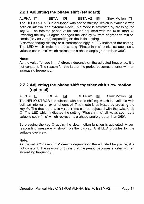
2.2.1 Adjusting the phase shift (standard)
ALPHA BETA BETA A2 Slow Motion The HELIO-STROB is equipped with phase shifting, which is available with both an internal and external clock. This mode is activated by pressing the key . The desired phase value can be adjusted with the twist knob . Pressing the key again changes the display from degrees to millise- conds (or vice versa) depending on the initial setting. A corresponding display or a correspondingly lit LED indicates the setting. The LED which indicates the setting “Phase in ms” blinks as soon as a value is set in “ms” which represents a phase angle greater than 360°. Note: As the value “phase in ms“ directly depends on the adjusted frequence, it is not constant. The reason for this is that the period becomes shorter with an increasing frequency.
2.2.2 Adjusting the phase shift together with slow motion (optional)
ALPHA BETA BETA A2 Slow Motion The HELIO-STROB is equipped with phase shifting, which is available with both an internal or external control. This mode is activated by pressing the key . The desired phase value in ms can be adjusted with the twist knob . The LED which indicates the setting “Phase in ms” blinks as soon as a value is set in “ms” which represents a phase angle greater than 360°. By pressing the key again, the slow motion function is activated. A cor-responding message is shown on the display. A lit LED provides for the suitable overview. Note: As the value “phase in ms“ directly depends on the adjusted frequence, it is not constant. The reason for this is that the period becomes shorter with an increasing frequency.
Page 18 Operation Manual HELIO-STROB ALPHA, BETA, BETA A2
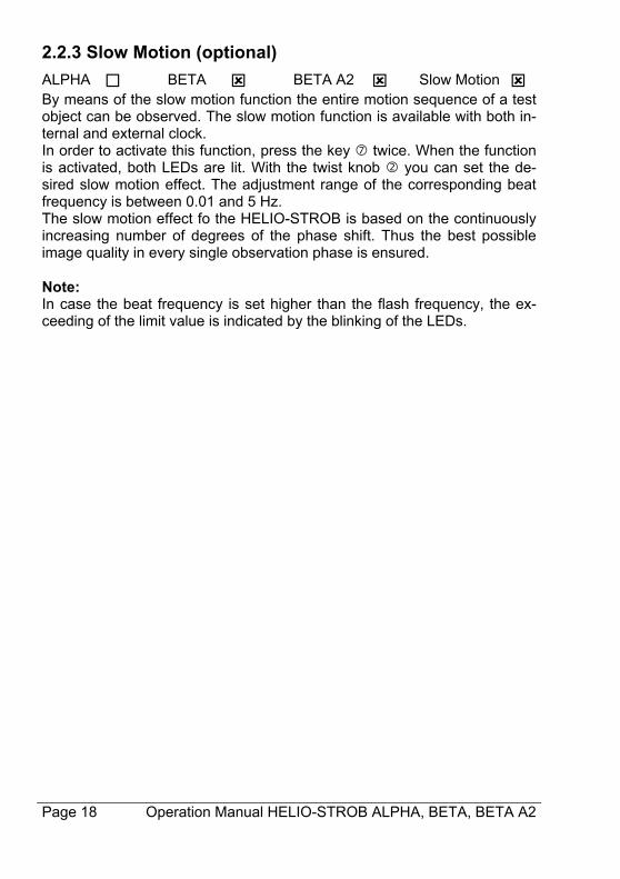
2.2.3 Slow Motion (optional)
ALPHA BETA BETA A2 Slow Motion By means of the slow motion function the entire motion sequence of a test object can be observed. The slow motion function is available with both in-ternal and external clock. In order to activate this function, press the key twice. When the function is activated, both LEDs are lit. With the twist knob you can set the de-sired slow motion effect. The adjustment range of the corresponding beat frequency is between 0.01 and 5 Hz. The slow motion effect fo the HELIO-STROB is based on the continuously increasing number of degrees of the phase shift. Thus the best possible image quality in every single observation phase is ensured. Note: In case the beat frequency is set higher than the flash frequency, the ex-ceeding of the limit value is indicated by the blinking of the LEDs.
Operation Manual HELIO-STROB ALPHA, BETA, BETA A2 Page 19
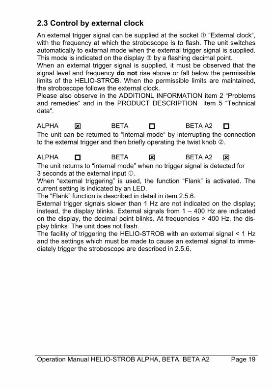
2.3 Control by external clock
An external trigger signal can be supplied at the socket “External clock“, with the frequency at which the stroboscope is to flash. The unit switches automatically to external mode when the external trigger signal is supplied. This mode is indicated on the display by a flashing decimal point. When an external trigger signal is supplied, it must be observed that the signal level and frequency do not rise above or fall below the permissible limits of the HELIO-STROB. When the permissible limits are maintained, the stroboscope follows the external clock. Please also observe in the ADDITIONL INFORMATION item 2 “Problems and remedies“ and in the PRODUCT DESCRIPTION item 5 “Technical data“. ALPHA BETA BETA A2 The unit can be returned to “internal mode“ by interrupting the connection to the external trigger and then briefly operating the twist knob . ALPHA BETA BETA A2 The unit returns to “internal mode” when no trigger signal is detected for 3 seconds at the external input . When “external triggering” is used, the function “Flank” is activated. The current setting is indicated by an LED. The “Flank” function is described in detail in item 2.5.6. External trigger signals slower than 1 Hz are not indicated on the display; instead, the display blinks. External signals from 1 – 400 Hz are indicated on the display, the decimal point blinks. At frequencies > 400 Hz, the dis-play blinks. The unit does not flash. The facility of triggering the HELIO-STROB with an external signal < 1 Hz and the settings which must be made to cause an external signal to imme-diately trigger the stroboscope are described in 2.5.6.
Page 20 Operation Manual HELIO-STROB ALPHA, BETA, BETA A2
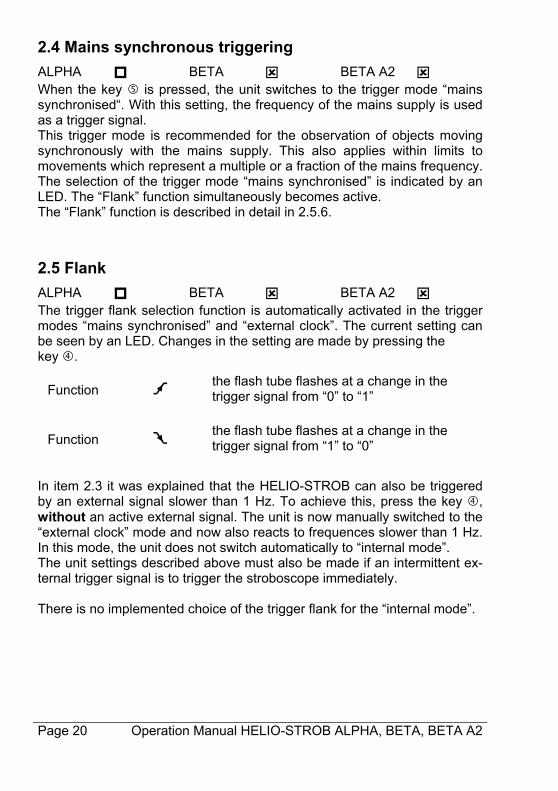
2.4 Mains synchronous triggering
ALPHA BETA BETA A2 When the key is pressed, the unit switches to the trigger mode “mains synchronised“. With this setting, the frequency of the mains supply is used as a trigger signal. This trigger mode is recommended for the observation of objects moving synchronously with the mains supply. This also applies within limits to movements which represent a multiple or a fraction of the mains frequency. The selection of the trigger mode “mains synchronised” is indicated by an LED. The “Flank” function simultaneously becomes active. The “Flank” function is described in detail in 2.5.6.
2.5 Flank
ALPHA BETA BETA A2 The trigger flank selection function is automatically activated in the trigger modes “mains synchronised” and “external clock”. The current setting can be seen by an LED. Changes in the setting are made by pressing the key .
Function
the flash tube flashes at a change in the trigger signal from “0” to “1”
Function
the flash tube flashes at a change in the trigger signal from “1” to “0”
In item 2.3 it was explained that the HELIO-STROB can also be triggered by an external signal slower than 1 Hz. To achieve this, press the key , without an active external signal. The unit is now manually switched to the “external clock” mode and now also reacts to frequences slower than 1 Hz. In this mode, the unit does not switch automatically to “internal mode”. The unit settings described above must also be made if an intermittent ex-ternal trigger signal is to trigger the stroboscope immediately. There is no implemented choice of the trigger flank for the “internal mode”.

Operation Manual HELIO-STROB ALPHA, BETA, BETA A2 Page 21
2.6 Power control - dimmer
ALPHA BETA BETA A2 Upon pressing the “dimmer“ key the minimum brightness level is ad-justed – independently of the respective frequency. This offers the possibil-ity to work within the entire frequency range with the same brightness. This function can be chosen in all operation modes of the HELIO-STROB and is indicated by an LED.
2.7 Trigger output
The HELIO-STROB is equipped with a trigger output, to control different devices. The signal between pin 4 and pin 1 of the socket “external clock” corresponds to the TTL level. The period duration depends on the flash rate, TLOW is constant (200µs). Signal:
Page 22 Operation Manual HELIO-STROB ALPHA, BETA, BETA A2
Maintenance
1. Storage
Protect the instrument from damage by properly storing it in a dry room.
To avoid condensation see that the storage temperature is kept. Storage temp.: -20°C .... +60°C (warming time constant >10K/h)
2. Maintenance
According to the design, the HELIO-STROB is not susceptible to distur-bance. However, the following should be basically observed: Do not throw the instrument and do not expose it to heavy shocks. Protect the device from potential damage Clean the instrument by using only a soft, lightly-moist cloth. Use only
mild detergents.
3. Inspection / Calibration
To maintain the reliability and the high quality standard of the HELIO-STROB over a long period of time, the instrument should be inspected by the manufacturer each year. During inspections, all instrument specific functions are checked. A PTB (Physikalisch-Technische Bundesanstalt, the German Bureau of Stan-dards) traceable manufacturer certificate is available on request. The re-sults of inspections shall be documented in inspection sheets and stored in a database.
4. Repairs / Disposal
Instruments which are damaged or do not perform according to their speci-fications shall no longer be used. To provide for a safe and functional in-strument, only original spare parts shall be used for repair.
To dispose of the old instrument according to legal rules and provisions, please send the HELIO-STROB to the manufactu-rer.
Operation Manual HELIO-STROB ALPHA, BETA, BETA A2 Page 23
If your instrument requires inspection / repair or disposal, please send the unit DAP to: ELMED Dr.Ing. Mense GmbH Stroboscope-Service Weilenburgstr. 39 D-42579 Heiligenhaus
Proper execution of maintenance and repair is guaranteed only by the manufacturer or by qualified and authorised service cen-ters.
Page 24 Operation Manual HELIO-STROB ALPHA, BETA, BETA A2
Additional Information
1. Pin assignments
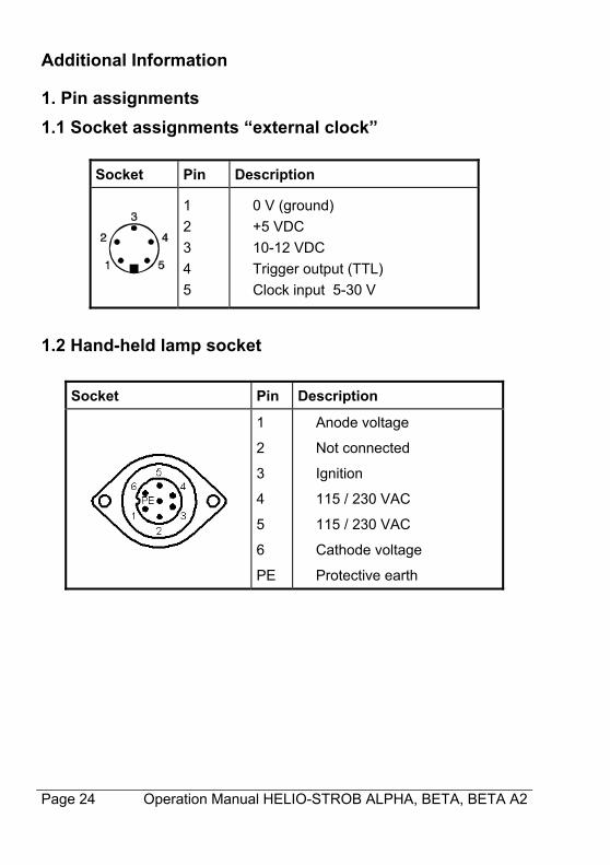
1.1 Socket assignments “external clock”
Socket Pin Description
1
2
3
4
5
0 V (ground)
+5 VDC
10-12 VDC
Trigger output (TTL)
Clock input 5-30 V
1.2 Hand-held lamp socket
Socket Pin Description
1
2
3
4
5
6
PE
Anode voltage
Not connected
Ignition
115 / 230 VAC
115 / 230 VAC
Cathode voltage
Protective earth
Operation Manual HELIO-STROB ALPHA, BETA, BETA A2 Page 25
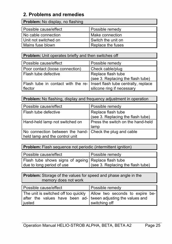
2. Problems and remedies
Problem: No display, no flashing
Possible cause/effect Possible remedy No cable connection Make connection Unit not switched on Switch the unit on Mains fuse blown Replace the fuses Problem: Unit operates briefly and then switches off
Possible cause/effect Possible remedy Poor contact (loose connection) Check cable/plug Flash tube defective Replace flash tube
(see 3. Replacing the flash tube) Flash tube in contact with the re-flector
Insert flash tube centrally, replace silicone ring if necessary
Problem: No flashing, display and frequency adjustment in operation
Possible cause/effect Possible remedy Flash tube defective Replace flash tube
(see 3. Replacing the flash tube) Hand-held lamp not switched on Press the switch on the hand-held
lamp No connection between the hand-held lamp and the control unit
Check the plug and cable
Problem: Flash sequence not periodic (intermittent ignition)
Possible cause/effect Possible remedy Flash tube shows signs of ageing due to long period of use
Replace flash tube (see 3. Replacing the flash tube)
Problem: Storage of the values for speed and phase angle in the memory does not work
Possible cause/effect Possible remedy The unit is switched off too quickly after the values have been ad-justed
Allow two seconds to expire be-tween adjusting the values and switching off
Page 26 Operation Manual HELIO-STROB ALPHA, BETA, BETA A2
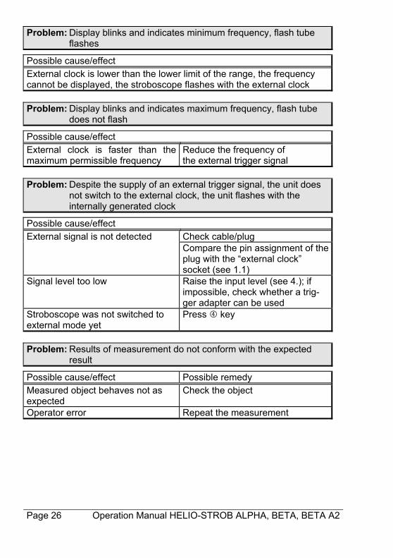
Problem: Display blinks and indicates minimum frequency, flash tube flashes
Possible cause/effect External clock is lower than the lower limit of the range, the frequency cannot be displayed, the stroboscope flashes with the external clock Problem: Display blinks and indicates maximum frequency, flash tube does not flash
Possible cause/effect External clock is faster than the maximum permissible frequency
Reduce the frequency of the external trigger signal
Problem: Despite the supply of an external trigger signal, the unit does not switch to the external clock, the unit flashes with the internally generated clock
Possible cause/effect External signal is not detected Check cable/plug
Compare the pin assignment of theplug with the “external clock” socket (see 1.1)
Signal level too low Raise the input level (see 4.); if impossible, check whether a trig-ger adapter can be used
Stroboscope was not switched to external mode yet
Press key
Problem: Results of measurement do not conform with the expected result
Possible cause/effect Possible remedy Measured object behaves not as expected
Check the object
Operator error Repeat the measurement
Operation Manual HELIO-STROB ALPHA, BETA, BETA A2 Page 27
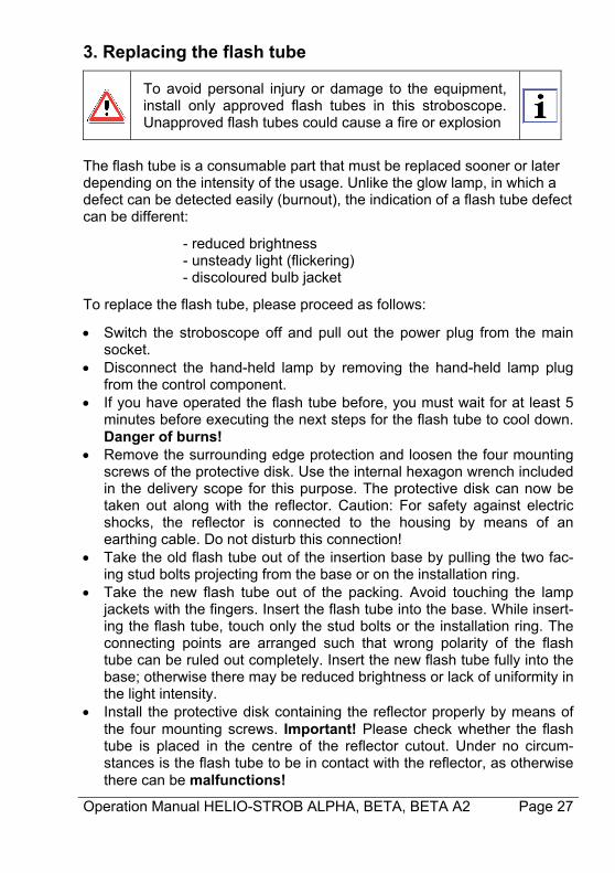
3. Replacing the flash tube
To avoid personal injury or damage to the equipment, install only approved flash tubes in this stroboscope. Unapproved flash tubes could cause a fire or explosion
The flash tube is a consumable part that must be replaced sooner or later depending on the intensity of the usage. Unlike the glow lamp, in which a defect can be detected easily (burnout), the indication of a flash tube defect can be different:
- reduced brightness - unsteady light (flickering)
- discoloured bulb jacket
To replace the flash tube, please proceed as follows:
Switch the stroboscope off and pull out the power plug from the main socket.
Disconnect the hand-held lamp by removing the hand-held lamp plug from the control component.
If you have operated the flash tube before, you must wait for at least 5 minutes before executing the next steps for the flash tube to cool down. Danger of burns!
Remove the surrounding edge protection and loosen the four mounting screws of the protective disk. Use the internal hexagon wrench included in the delivery scope for this purpose. The protective disk can now be taken out along with the reflector. Caution: For safety against electric shocks, the reflector is connected to the housing by means of an earthing cable. Do not disturb this connection!
Take the old flash tube out of the insertion base by pulling the two fac-ing stud bolts projecting from the base or on the installation ring.
Take the new flash tube out of the packing. Avoid touching the lamp jackets with the fingers. Insert the flash tube into the base. While insert-ing the flash tube, touch only the stud bolts or the installation ring. The connecting points are arranged such that wrong polarity of the flash tube can be ruled out completely. Insert the new flash tube fully into the base; otherwise there may be reduced brightness or lack of uniformity in the light intensity.
Install the protective disk containing the reflector properly by means of the four mounting screws. Important! Please check whether the flash tube is placed in the centre of the reflector cutout. Under no circum-stances is the flash tube to be in contact with the reflector, as otherwise there can be malfunctions!
Page 28 Operation Manual HELIO-STROB ALPHA, BETA, BETA A2
Please also check the silicon ring in the reflector for damages; it pro-vides protection against flashovers between flash tube and reflector.
Finally, replace the edge protection on the hand-held lamp housing.