operational notes on distance measuring equipment contents · pdf fileoperational notes on...
TRANSCRIPT
Operational Notes on Distance Measuring Equipment Contents
i
Disclaimer These notes are a reproduction of a booklet originally published by the Civil Aviation Authority. Although these notes are no longer in print, they continue to provide a valuable resource and are made available as reference material for students, pilots and instructors. The notes have not been edited, and as they were written 20 or more years ago, may contain information relating to systems that are no longer in production or have been modernised. 1. Introduction.................................................................................................................................1-1 2. DME-Principles of Operation ......................................................................................................2-1 3. Aircraft Equipment......................................................................................................................3-1 4. Principles of Operational Use .....................................................................................................4-1
4.1 Provision of Navigation Fixes................................................................................................4-2 4.2 Computation of Groundspeed...............................................................................................4-3
5. DME Arrivals ..............................................................................................................................5-1

Operational Notes on Distance Measuring Equipment 1. Introduction
These notes are a reproduction of a booklet originally 1-1 published by the Civil Aviation Authority
Knowledge of the aircraft’s position is a basic requirement for air navigation and one means of satisfying this requirement is to present the pilot with bearing and distance information. Bearing information may be derived in a variety of ways, some of which are via VOR or ADF systems. Distance information may be derived from radar or by DME, which is a form of radar.
In primary radar a short pulse is transmitted and the time interval from transmission to reception of the reflected pulse is measured. As the speed of an electromagnetic pulse through the atmosphere is 300 000 kilometres per second, or one nautical mile in 6.2 micro-seconds, the distance between the transmitter and the target can be calculated. In the case of a radar sited on the ground an aircraft target may be easily identified and the distance measured readily due to its relative freedom from other reflecting objects. If a radar is installed in an aircraft, precise identification of specific ground targets, for all practical purposes, is very difficult to effect due to mass reflection from surrounding objects. Hence primary radar is supplemented by additional equipment at the target to enable distance to be reliably measured to the necessary degree of accuracy. When primary radar is supplemented to accomplish this task it then becomes a form of secondary radar.
In secondary radar, pulses known as interrogation pulses are transmitted and when received at the target they are passed through a ‘gate’ and then trigger transmission of reply pulses back to the initial source where the time interval may be measured and displayed as distance. The ‘gate’ in the target receiver is an electronic device which is preset to receive only matching pulses.
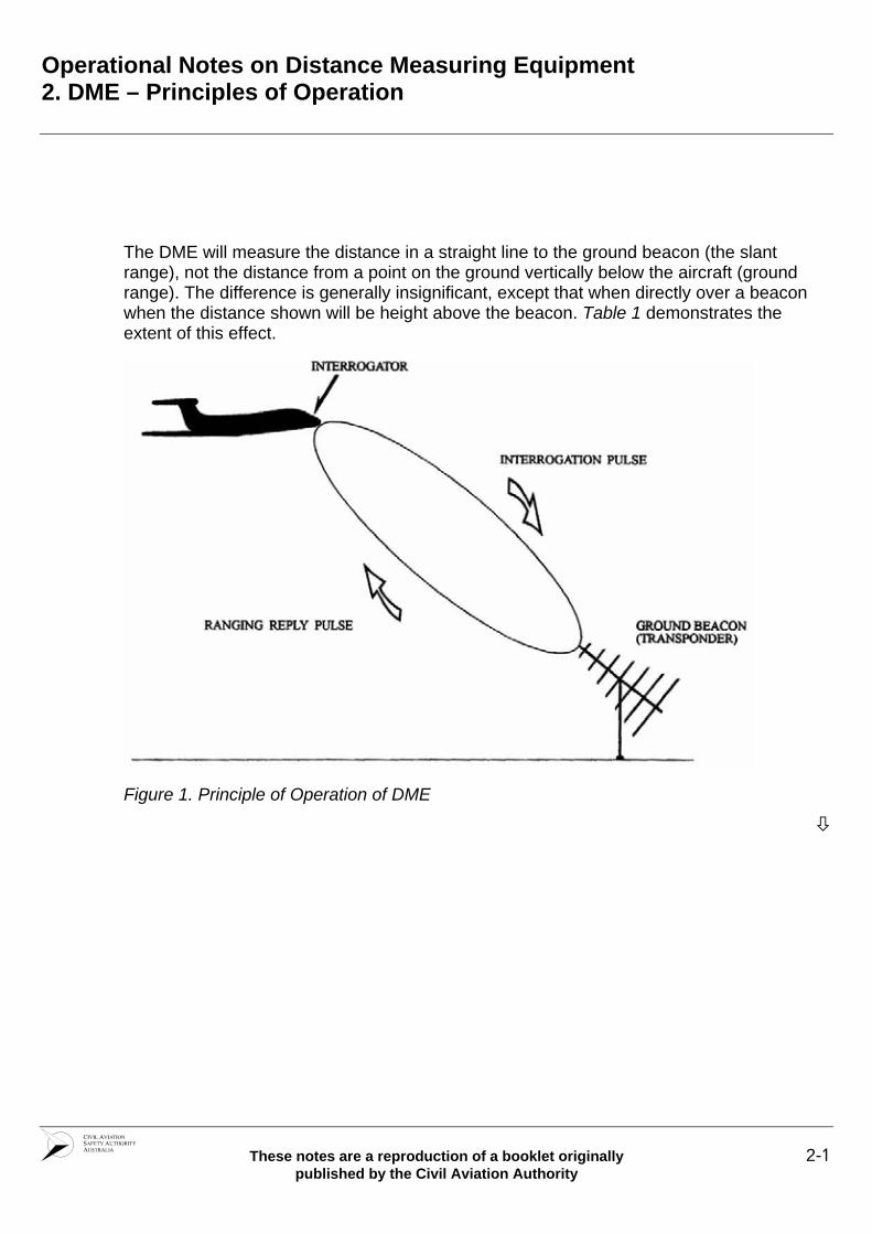
In the DME system the interrogating equipment, known as the ‘Interrogator’, is installed in the aircraft and the target, located on the ground, is referred to as the ‘Transponder’ or ‘Ground Beacon’. (See Figure 1.)
DME complies with the standards prescribed by the International Civil Aviation Organisation (ICAO) and is installed at all international airports, at all capital city airports and many regional airports in Australia and along routes serving international traffic. It was developed from a composite distance and bearing facility known as ‘Tactical Air Navigation’ (TACAN) which was designed in the USA as an aid to military aircraft. The VOR fulfills the bearing requirements for civil aviation navigation, hence this component of the TACAN system is not used to assist civil air operations. A combined VOR/TACAN installation is commonly referred to as ‘VORTAC’. Where TACAN is not installed for military purposes then a DME, manufactured to the same specifications as the DME portion of TACAN, is installed. This is referred to as VOR/DME.
A DME system developed in Australia, called DMEA, was decommissioned in December 1995.

Operational Notes on Distance Measuring Equipment 2. DME – Principles of Operation
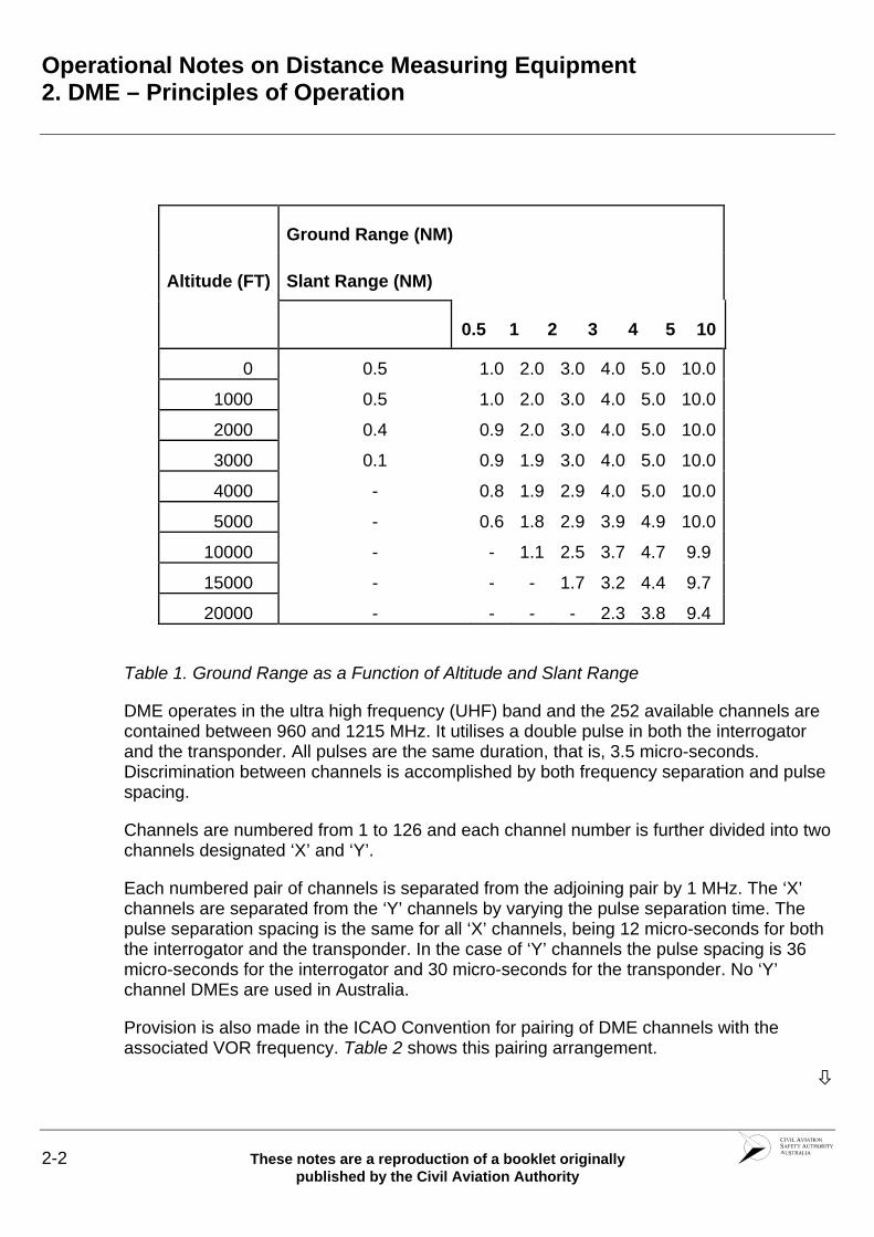
The DME will measure the distance in a straight line to the ground beacon (the slant range), not the distance from a point on the ground vertically below the aircraft (ground range). The difference is generally insignificant, except that when directly over a beacon when the distance shown will be height above the beacon. Table 1 demonstrates the extent of this effect.
Figure 1. Principle of Operation of DME
These notes are a reproduction of a booklet originally 2-1 published by the Civil Aviation Authority
Operational Notes on Distance Measuring Equipment 2. DME – Principles of Operation
2-2 These notes are a reproduction of a booklet originally published by the Civil Aviation Authority
Ground Range (NM)
Slant Range (NM) Altitude (FT)
0.5 1 2 3 4 5 10
0 0.5 1.0 2.0 3.0 4.0 5.0 10.0
1000 0.5 1.0 2.0 3.0 4.0 5.0 10.0
2000 0.4 0.9 2.0 3.0 4.0 5.0 10.0
3000 0.1 0.9 1.9 3.0 4.0 5.0 10.0
4000 - 0.8 1.9 2.9 4.0 5.0 10.0
5000 - 0.6 1.8 2.9 3.9 4.9 10.0
10000 - - 1.1 2.5 3.7 4.7 9.9
15000 - - - 1.7 3.2 4.4 9.7
20000 - - - - 2.3 3.8 9.4
Table 1. Ground Range as a Function of Altitude and Slant Range
DME operates in the ultra high frequency (UHF) band and the 252 available channels are contained between 960 and 1215 MHz. It utilises a double pulse in both the interrogator and the transponder. All pulses are the same duration, that is, 3.5 micro-seconds. Discrimination between channels is accomplished by both frequency separation and pulse spacing.
Channels are numbered from 1 to 126 and each channel number is further divided into two channels designated ‘X’ and ‘Y’.
Each numbered pair of channels is separated from the adjoining pair by 1 MHz. The ‘X’ channels are separated from the ‘Y’ channels by varying the pulse separation time. The pulse separation spacing is the same for all ‘X’ channels, being 12 micro-seconds for both the interrogator and the transponder. In the case of ‘Y’ channels the pulse spacing is 36 micro-seconds for the interrogator and 30 micro-seconds for the transponder. No ‘Y’ channel DMEs are used in Australia.
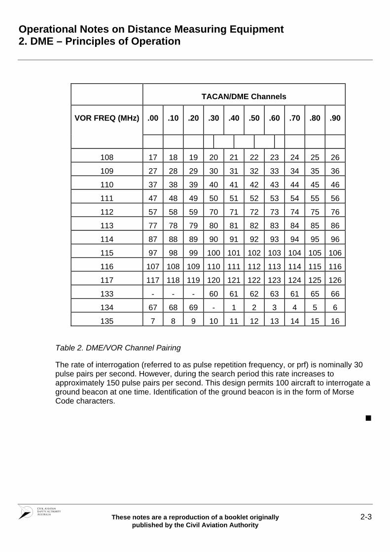
Provision is also made in the ICAO Convention for pairing of DME channels with the associated VOR frequency. Table 2 shows this pairing arrangement.
Operational Notes on Distance Measuring Equipment 2. DME – Principles of Operation
These notes are a reproduction of a booklet originally 2-3 published by the Civil Aviation Authority
TACAN/DME Channels
.00 .10 .20 .30 .40 .50 . . . .60 70 80 90 VOR FREQ (MHz)
108 17 18 19 20 21 22 2 2 2 23 4 5 6
109 27 28 29 30 31 32 3 3 3 33 4 5 6
110 37 38 39 40 41 42 4 4 4 43 4 5 6
111 47 48 49 50 51 52 5 5 5 53 4 5 6
112 57 58 59 70 71 72 7 7 7 73 4 5 6
113 77 78 79 80 81 82 8 8 8 83 4 5 6
114 87 88 89 90 91 92 9 9 9 93 4 5 6
115 97 98 99 100 101 1 1 102 03 104 105 06
116 107 108 109 110 111 1 1 112 13 114 115 16
117 117 118 119 120 121 1 1 122 23 124 125 26
133 - - - 60 61 6 6 6 6 62 3 1 5 6
134 67 68 69 - 1 2 3 4 5 6
135 7 8 9 10 11 12 1 1 1 13 4 5 6
Table 2. DME/VOR Channel Pairing
The rate of interrogation (referred to as pulse repetition frequency, or prf) is nominally 30 pulse pairs per second. However, during the search period this rate increases to approximately 150 pulse pairs per second. This design permits 100 aircraft to interrogate a ground beacon at one time. Identification of the ground beacon is in the form of Morse Code characters.

Operational Notes on Distance Measuring Equipment 3. Aircraft Equipment
These notes are a reproduction of a booklet originally 3-1 published by the Civil Aviation Authority
3. Aircraft Equipment
DME receivers, or interrogators, are produced by a number of manufacturers. Some DME interrogators provide a 300 nautical mile range and may also give rate of closure information. Many interrogators have an automatic in-built self test facility. Normally, DME interrogators do not have a separate control unit, the equipment being controlled from a common ‘VHF NAV’ control unit. The appropriate DME channel is selected automatically when a VOR frequency is selected. There are also a limited number of ILS installations where DME is co-sited to provide distance to threshold information and this is available by frequency pairing with the selected ILS. Where only a TACAN beacon is available appropriate selection is made by referring to the TACAN channel number at Table 2 which will provide a pseudo ‘VHF NAV’ pairing frequency which can be selected in the normal way.

Operational Notes on Distance Measuring Equipment 4. Principles of Operational Use
These notes are a reproduction of a booklet originally 4-1 published by the Civil Aviation Authority
4. Principles of Operational Use
DME equipment should be operated in accordance with the manufacturer’s instructions for the particular equipment. The sequence of operation is, however, generally as follows:
1. Switch on the equipment
2. When the equipment indicates it is searching, select the ‘VHF NAV’ paring frequency required as specified in the AIP (ERSA or DAP)
3. When the interrogator locks on, check the Morse Code identification of the beacon to ensure that the correct frequency has been selected.

Operational Notes on Distance Measuring Equipment 4. Principles of Operational Use 4.1 Provision of Navigation Fixes
4-2 These notes are a reproduction of a booklet originally published by the Civil Aviation Authority
DME Plus NDB or VOR
In conjunction with a position line from an NDB or VOR, a DME distance can provide a positive fix—the DME distance is a position line in the form of a circle with radius equal to the DME distance and with its centre at the DME beacon.
DME Plus DME
DME distances from two suitably located DME beacons can give a positive fix at the intersection of the two DME distance position lines (arcs).
Note: For a positive fix two position lines must intersect at an angle of not less than 45°, as specified in AIPRAC paragraph 44.6.2.

Operational Notes on Distance Measuring Equipment 4. Principles of Operational Use 4.2 Computation of Groundspeed
These notes are a reproduction of a booklet originally 4-3 published by the Civil Aviation Authority
Where an aircraft is proceeding directly towards or away from a DME beacon, the groundspeed may be calculated by noting the miles flown over a given time. Note that this method will be less accurate as the DME beacon is neared, as the slant range will gradually approach the value of the aircraft altitude (see Table 1).

Operational Notes on Distance Measuring Equipment 5. DME Arrivals
These notes are a reproduction of a booklet originally 5-1 published by the Civil Aviation Authority
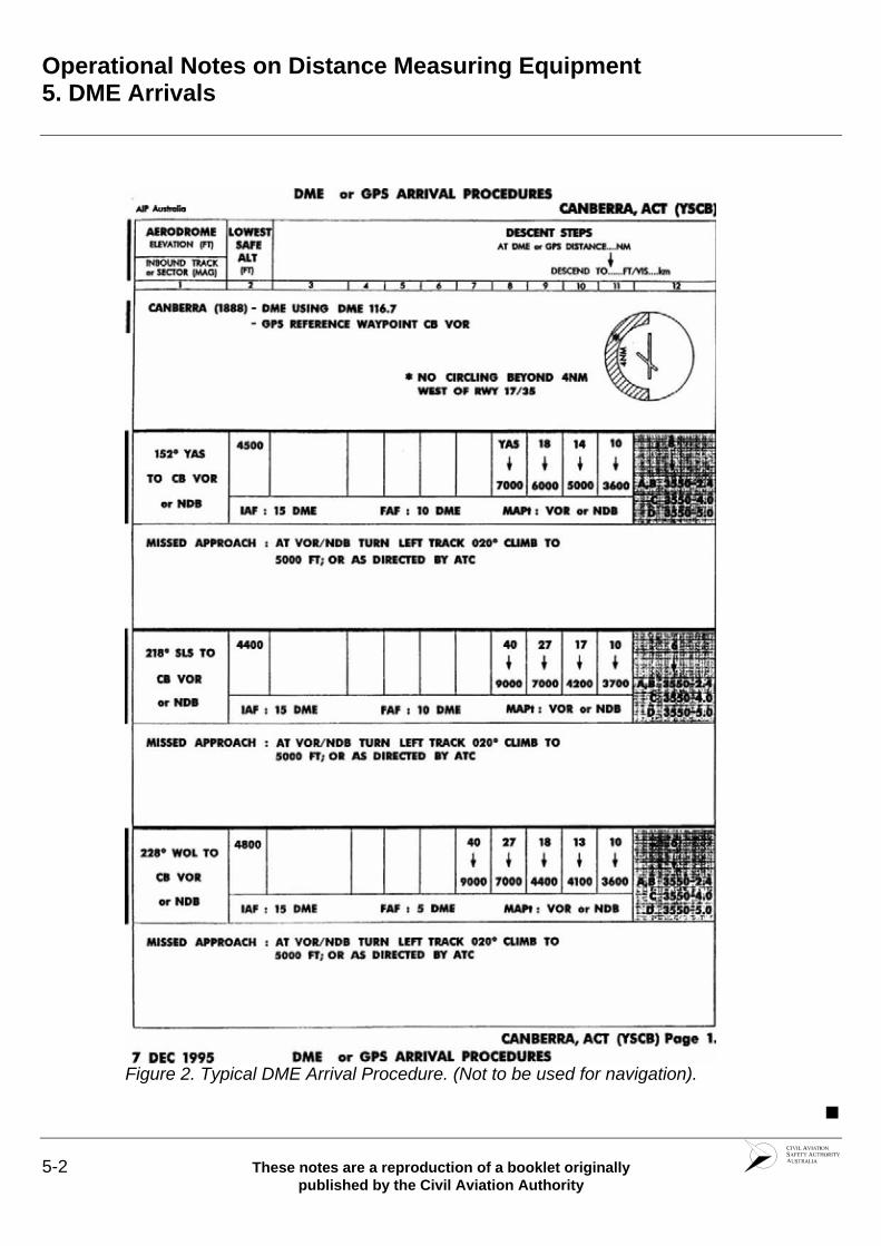
A DME Arrival is an instrument approach procedure which requires an aircraft to track towards an aerodrome using NDB, VOR, or LLZ and descend in steps at specified distances. This type of approach permits an aircraft to descend below the lowest safe altitude for the route segment and arrive over the destination aerodrome, in most cases, at the circling minimum altitude. In some cases, however, the DME Arrival terminates at a position and altitude from which a specific instrument approach can be commenced.
The steps in the DME Arrival are designed to provide adequate terrain clearance and where the approach is in controlled airspace they are designed to keep the aircraft in controlled airspace. Allowance is made in the procedure for possible equipment errors in the DME distance indication. Figure 2 shows an example of a DME Arrival procedure.
Instructions on the use of DME Arrival procedures are contained in the DAP section of the AIP.
Operational Notes on Distance Measuring Equipment 5. DME Arrivals
Figure 2. Typical DME Arrival Procedure. (Not to be used for navigation).
5-2 These notes are a reproduction of a booklet originally published by the Civil Aviation Authority