operator and parts manual roto tub grinder model 760 · s.n. 1500098 to 1883094 roto grind operator...
TRANSCRIPT

S.N. 1500098 to 1883094
ROTO GRIND
OPERATOR AND PARTS MANUAL
TUB GRINDER
MODEL 760
BURROWS ENTERPRISES, INC.
2024 East 8th Street
Greeley, Colorado 80631
970-353-3769 * Fax 970-353-0839
ROTO
GRIND

TABLE OF CONTENTS
LIMITED WARRANTY 2
TO THE OWNER 3
SAFETY DECALS 5
SAFETY DECAL LOCATIONS 6
GENERAL OPERATION 7
MAINTENANCE 10
LOAD SENSING SWITCH 11
TORQUE SPECIFICATIONS 12
LOAD SENSOR WIRING DIAGRAM 12
PARTS LISTING:
MAIN DRIVE ASSEMBLY 13
HYDRAULICS AND GOVERNOR 14
TUB AND SHIELDS 15
ROTOR ASSEMBLY 16
WHEEL AND HUB ASSEMBLY 17
SPOUT ASSEMBLY 18
PTO DRIVE LINE ASSEMBLY 19
MILL HOUSING PARTS AND ACCESSORIES 20
CORN AND GRAIN ATTACHMENTS 21
BALE TURNER ATTACHMENTS 22

LIMITED WARRANTY
The Burrows Enterprises Incorporated warrants products sold by it to be free from defects in material and
workmanship for a period of one (1) year for agricultural applications and for a period of ninety (90) days for
industrial applications after the date of delivery to the first purchaser subject to the following conditions:
1. Burrows Enterprises Incorporated's obligation and liability under this warranty is to repair or replace at
the company's option, any parts which upon manufacture were defective in material or workmanship.
2. All parts and repairs under this warranty shall be supplied at an authorized Burrows Enterprises
Incorporated dealer or at the factory at the option of Burrows Enterprises Incorporated.
3. Burrows Enterprises Incorporated's warranty does not extend to parts and elements not manufactured by
Burrows Enterprises Incorporated and which carry the warranty of the other manufacturer.
4. Transportation or shipping to an authorized dealer for necessary repairs is at the expense of the purchaser.
5. Burrows Enterprises Incorporated MAKES NO OTHER WARRANTY EXPRESS OR IMPLIED AND
MAKES NO WARRANTY OF MERCHANTABILITY OR FITNESS FOR ANY PARTICULAR PURPOSE
BEYOND THAT EXPRESSLY STATED IN THIS WARRANTY. Burrows Enterprises Incorporated's
LIABILITY IS LIMITED TO THE TERMS SET FORTH IN THIS WARRANTY AND DOES NOT
INCLUDE ANY LIABll.JTY FOR DIRECT, INDIRECT, INCIDENTAL OR CONSEQUENTIAL
DAMAGES OR EXPENSE OF DELAY AND THE COMPANY'S LIABILITY IS LIMITED TO REPAIR OR
REPLACEMENT OF DEFECTIVE PARTS AS SET FORTH HEREIN IN THE WARRANTY.
6. Any improper use, including operation after discovery of defective or worn parts, operation beyond rated
capacity, substitution or parts not approved by Burrows Enterprises Incorporated, or any alteration or repair by
other than an authorized Burrows Enterprises Incorporated dealer which affects the product materially and
adversely, shall void this warranty.
7. No dealer, employee, or representative is authorized to change this warranty in any way or grant any other
warranty unless such change is made in writing and signed by an officer of Burrows Enterprises Incorporated
at its home office.
8. Some states do not allow limitations on how long an implied warranty lasts or exclusions of or limitations on
relief such as incidental or consequential damages so the above limitations or exclusions may not apply to you.
This warranty gives you specific legal rights and you may have other rights which vary from state to state.
INFORMATON FOR ORDERING PARTS
Burrows Enterprises Incorporated reserves the right to make changes or add improvements to its products at any time without incurring any
obligation to make such changes to products manufactured previously. Burrows Enterprises Incorporated, or its dealers, accept no
responsibility for variations which may be evident in the actual specifications of its products and the statements and descriptions contained in this
publication.
OWNERS NAME.
ADDRESS
DEALERS NAME
ADDRESS
SERIAL NUMBER
(FOR LOCATION SEE PAGE 6)
DATE PURCHASED

TO THE OWNER
This Burrows unit is the finest equipment made and the purpose of this manual is to assist you in
realizing the benefits you anticipated when you purchased this unit. Many people have contributed to
the production of this product. They all have an interest in its successful performance and we are
providing this manual to give you the benefit of the experience we have gained thorough the years of
building and testing this equipment. The way you operate and the care you give this unit will have much
to do with the successful performance of this unit. This operators manual has been carefully prepared
and illustrated to make it as easy as possible for you in the operation of your unit. It will pay you to read
the entire manual carefully and familiarize yourself with all operations "before operating" the unit.
For further information call or write:
BURROWS ENTERPRISES, INC.
2024 East 8th Street
Greeley, Colorado 80631
970-353-3769 * Fax 970-353-0839
SPECIAL PRECAUTIONS
1. Do not climb on, or stand on the unit when it is turned by the P. T .0. of the tractor. All moving
parts are guarded for your protection but foreign objects such as rocks and pieces of iron can be thrown
out of the tub as it runs empty of material.
2. Leave all shields and guards on the machine while operating. They are for your protection and
removal of them will hinder the operation of the machine. Warranty is void if the machine is operated
with any of the shields missing.
3. The ROTO Grind is designed to be turned at 1000 R.P.M. with tractor power take off. Do not,
under any circumstances, turn the mill over 1250 R.P .M. or serious damage could result to the
machine. Do not operate at 540 R.P .M. unless application is approved in writing from a Burrows
Enterprises Inc. officer. Failure to operate at other R.P.M.'s will void warranty.
4. The ROTO Grind is designed to grind roughage materials either loose or baled. The machines are
equipped with twine guards and will keep almost all of the sisal twine from wrapping on the rotor shaft
if they are adjusted properly, however the shaft should be checked periodically for twine build up and
removed if any has accumulated.
Plastic twine should not be ground because it is not only non-digestible, it is more likely to wrap on the
rotor shaft. Any plastic twine build up will create heat and melt into a solid lug that can only be
removed by burning it off.
5. In loose material, the ROTO Grind will operate with more capacity if the size of the bites of
material being loaded are small enough to fit into the tub. Do not allow material to hang over the side of
the tub. This will cause a bridging effect and will slow up grinding.
6. Do not attempt to grind foreign materials such as rocks, bricks, dirt, sand, and any type metal pieces
or products, tree branches over 3" in diameter, glass, and ceramics. These products can damage the
machine and voids warranty.

WORK SAFELY –FOLLOW THESE RULES
This safety alert symbol identifies important safety messages in this manual.
It means -ATTENTION! BECOME ALERT! YOUR SAFETY IS INVOLVED !
When you see this symbol, be alert to the possibility of personal injury and read the message that follows
A CAREFUL OPERATOR IS THE BEST INSURANCE AGAINST AN ACCIDENT. BEFORE OPERATING:
-Review this entire manual.
-Do not wear loose fitting clothing which may catch in
moving parts.
-Use extreme care when making adjustments. Shut off
machine before making adjustments. Shut off tractor
and put key in pocket.
-After servicing, be sure all tools, or parts, or servicing
equipment are removed from the machine.
-Keep all safety shields in place.
-Make sure that there is no one near the machine before
operating.
-Be sure that the correct power take-off parts are used
and that, they are properly secured.
-Be sure the tractor power take-off is disengaged before
starting the tractor engine.
-Review all safety decals.
-Securely block unit before working on it.
-When working with flammable materials, be sure you
do not smoke.
DURING OPERATION: - No one other than the operator should ride on the
tractor.
- Do not attempt to remove any obstructions while
operating the machine. First shut off the tractor and put
key in pocket.
-Always -disengage -the -P. T .0., before transporting.
Do not open any covers and expose the rotor or belts
while they are rotating.
-Shut off the tractor engine and be sure to wait until all
moving parts have come to a complete stop before
adjusting, cleaning, or lubricating.
-Keep hands, feet, clothing and objects away
from moving parts.
-Use extreme care when transporting over uneven
or rough terrain.
-Keep all shields in place and in good
condition.
-Keep children away from machine in
operation.
-Have your fire extinguisher checked at regular
intervals and place it in a position on the unit
where it is readily accessible without reaching
over or around moving parts.
-Crop materials often have an extremely high rate
of flammability, which increases the possibility
of fires. A decrease in the risk can be attained by,
stopping the machine, shutting the tractor off,
and removing the key from the ignition and
placing it in your pocket. Then proceed to
remove accumulations of material from the
tractor, and the machine. Now check for any
parts that may be over heating.
TRANSPORTING and ON-HIGHWAY OPERATION: -Check clearance carefully before towing the
machine over bridges and into buildings.
-Always place the machine in the transport
position.
-For daytime and nighttime, accessory light and
devices should be used for adequate warning to
operators of other vehicles.
-Comply with your state and local laws
governing highway safety, and with regulations
when moving machinery on a highway.
-Drive at a reasonable speed to maintain
complete control of the machine at all times.
-When transporting on the highway, always use
a safety chain between the towing vehicle and
the machine.

SAFETY SIGNS
Located at strategic points on this machine are safety signs. These signs warn you of potential danger if
the warnings on the decals are not followed.
# 1 -"ROTO GRIND" Part No. 224-09
#2 -"ARROW"
Part No. 224-05
# 3 -"WARNING-
NOT A STEP"
Part No. 224-114
# 4 -"CAUTION -DO
NOT OPERATE MILL
ABOVE 1200 RPM"
Part No. 224-113
# 5 -"CAUTION -KEEP ALL
SHIELDS IN PLACE: STOP ENGINE
BEFORE LEAVING OPERATOR'S
POSITION" -Part No. 224-07 LISTS 8
BASIC RULES TO OBSERVED AT
ALL TIMES.
# 6 -"THROWN OBJECT
HAZARD-KEEPAWAY"
Part No. 224-03
NO.7 -"WARNING -AVOID
UNSAFE OPERATION OR
MAINTENANCE. "
Part No. 224-01 NO.8 -"HIGH PRESSURE
FLUID HAZARD"
Part No. 224-02
ROTO
GRIND
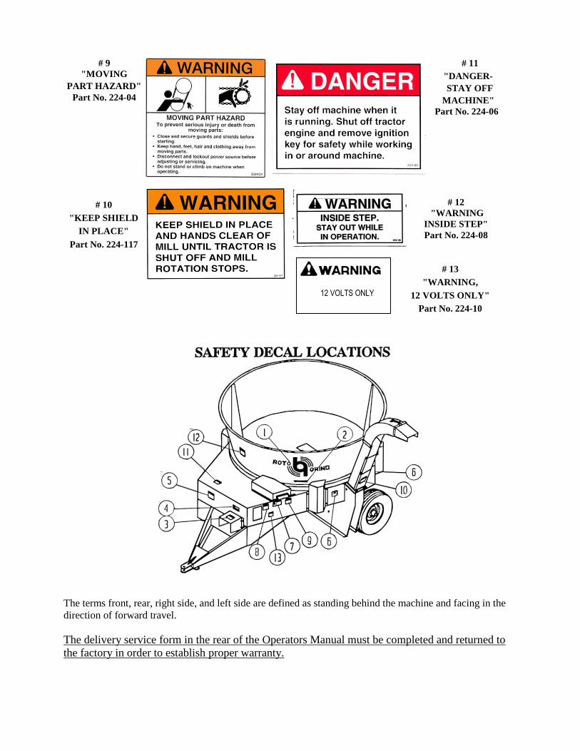
The terms front, rear, right side, and left side are defined as standing behind the machine and facing in the
direction of forward travel.
The delivery service form in the rear of the Operators Manual must be completed and returned to
the factory in order to establish proper warranty.
# 11
"DANGER-
STAY OFF
MACHINE"
Part No. 224-06
# 10
"KEEP SHIELD
IN PLACE"
Part No. 224-117
# 12
"WARNING
INSIDE STEP"
Part No. 224-08
# 9
"MOVING
PART HAZARD"
Part No. 224-04
# 13
"WARNING,
12 VOLTS ONLY"
Part No. 224-10
12 VOLTS ONLY

GENERAL OPERATION
IMPORTANT: BEFORE USING, WITH PTO CAUTION: NEVER PUT YOUR HANDS
DISENGAGED AND TRACTOR ENGINE INSIDE OF THE MACHINE DURING
STOPPED (KEY IN POCKET), INSPECT THE OPERATION, OR PERFORM ANY KIND OF MACHINE AND REMOVE ANY FOREIGN AN ADJUSTMENT, LUBRICATION, OR
OBJECTS WHICH MAY HAVE FALLEN REPAIR TO THE MACHINE WITHOUT
INTO THE MACHINE DURING TRANSIT. SHUTTING OFF THE TRACTOR IGNITION
AND PLACING KEY IN POCKET.
KEEP CHILDREN AWAY FROM MACHINE IN OPERATION
When corresponding with the company, distributor, or dealer regarding this machine, please specify both the model number and serial number.
1. SHEAR PLATES. These parts, in the mill housing assembly, control the fineness of grind of the
material. They are individually adjustable and for a very fine grind it is recommended that all of the shear
plates be positioned as close to the end of the hammers as possible. When coarser grinds are required,
move the top plates out first.
EXAMPLE: Top plate all the way out, the next plate, three quarters of the way out; the next one,
half way out and the fourth one down from the top, one quarter of the way out. Moving the top
plates out before the bottom ones, make the unit pull easier with less shock loads.
2. ADJUSTABLE RISER. Can be operated from the rear of the machine with a hand crank. For tough
grinding, or low horsepower, adjust the riser up by turning handle clockwise, for easier grinding, higher
horsepower and more capacity, lower the riser by turning the crank handle counter clockwise. Range is
from 5" to 9" above floor. Adjust in conjunction with the tub speed and how often the governor kicks in
and out.
3. HYDRAULICS. Tractor hydraulics is used to turn the tub. There is a dial mounted on the left front of
the machine that is a pressure compensated flow divider to control the rotation speed of the tub. This is to
be used in conjunction with height of risers to match the grinding speed to the tractor horsepower. Try to
avoid constant, very slow turning of the tub as this means that most of the oil is going through the
pressure side of the flow divider and tends to heat the oil. If the tub must be turned very slowly, check
the hydraulics periodically for heat. (Temperature should be kept below 150 degrees F.)
In the hydraulic circuit there is a normally open solenoid operated valve plumbed into the circuit
between the two hydraulic lines that run from the flow divider to the hydraulic motor. Being a normally
open valve, the oil will take the line of least resistance and will dump through this open valve and back to
the tractor instead of going through the hydraulic motor, which rotates the tub. The reason that the tub will
always turn backwards when the direction of the flow is reversed in the tractor is because there is a check
valve installed on the" out" side of this solenoid valve. The solenoid valve only works on the one direction
of flow of oil and you would not be able to ever turn the tub backwards without the check valve installed.
NOTE: Continuous grinding in the reverse tub rotation is not recommended. The flow divider is also
designed to work in one direction of flow and wants to let the tub turn at maximum RPM in the reverse
direction.

The function of the governor is to send an 12 volt current to the solenoid valve when the desired PTO
RPM is reached. This will close the valve and force the oil flow to go through the hydraulic motor and
rotate the tub in the proper clockwise rotation. When a heavy load lowers the PTO RPM, the governor
will cut off the 12 volt current to the valve and allow the valve to return to its normal open position which
lets the oil go through it instead of the hydraulic motor. This stops the tub rotation and allows the power
unit to return to normal speed at which time the governor will re-introduce the 12 volt current to the valve
to close it and the oil will again go through the hydraulic motor to start the tub rotation and resume
grinding.
Since the introduction of the " ALFALFA HAMMERS" which are designed to grind good
quality alfalfa at 540 RPM PTO speed instead of the normal 1000 RPM, it is necessary to reset
the governor to start and stop the tub at the lower RPM. In order to make the governor work at
the 540 RPM settings it is necessary to install a smaller sheave on the governor to speed it up,
or reset the controls on the AEC governor. There are some cases where the customer would
like to be able to grind at both 540 RPM for alfalfa and at 1000 RPM for other feeds. This
requires two front halves of the PTO to be able to switch speeds. The installation of all alfalfa
hammers in the machine, produces excessive" blow" at 1000 RPM. We recommend either half
alfalfa hammers and half standard hammers or a set of pins to tie the standard hammers to the
lead hammer. The reason that the hammers must be pinned together is that at the lower 540
RPM, the lead hammer is not heavy enough to stay extended to tear the material off of the
bale. Pinning them together adds the weight of the standard hammers plus the pin to the weight
momentum of the lead hammer which will keep it extended at the lower RPM's, and eliminate
excess wear on the hammer pin.
NOTE: CAUTION: 540 RPM operation is not recommended for tough grass hay grinding. It will rock the hammers
back to the point where the hammers will destroy the mill itself, and void your warranty.
ROTO GRIND HYDRAULIC SCHEMATIC
FLOW DIVIDER
TRACTOR INPUT HYURAULIC OIL FLOWS THROUGH
THE FLOW DIVIDER, SOLENOID & CHECK VALVE
UNTIL THE ROTOR REACHES OPERATING SPEED.
WHEN OPERATING SPEED IS REACHED, THE
GOVERNOR SENDS CURRENT TO THE NORMALLY
OPEN SOLENOID. THE SOLENOID CLOSES AND
SENDS FLUID TO THE HYDRAULIC MOTOR TO
ROTATE THE TUB.
SOLENOID
VALVE
HYDRAULIC MOTOR
SUPPLY LINE FROM TRACTOR
CONSTANT
FLOW
EXCESS
FLOW
CHECK VALVE
RETURN LINE TO TRACTOR

4. POWER TAKE OFF. The drive line is at a slight angle to the machine. Before starting the grinder,
move the front of the tractor to the right to straighten it. If it is not straight at the tractor joint it will cause
vibration and serious damage could result.
Always start the machine and check for operation of all parts prior to each day of
operation and after transporting. Materials and dirt can pack into the mill while transporting or over a
few days when it is windy. To prevent this from "locking" the mill you should step into the tub and roll
the mill backwards before you connect the machine to the tractor. Then, after the machine has been
properly connected to the tractor, set the tractor at low RPM and slowly engage the PTO clutch. If the
mill is still "locked", disengage the PTO, shut off the tractor, remove key and place in pocket, or in
absence of key (older model tractors), disconnect the PTO shaft from the tractor. Now step inside of the
tub and clean out the mill.
After you have finished grinding and want to shut the machine down, reduce the tractor RPM
slowly to an idle and wait for the mill to slow down before disengaging the PTO. Some tractors have a
brake on the PTO when disengaged and if disengaged at high RPM the weight of the rotor may damage
the PTO in your tractor
Set your draw bar to the correct operating length of 16" from the end of the PTO shaft on your
tractor to the center of the hole on your draw bar. Make sure that the square shaft is at least 8" into the
square shaft tube while in operation. If you are not engaged at least 8", you can cause damage to the PTO,
and voids the warranty.
DO NOT MOVE THE MACHINE WHILE THE PTO IS IN MOTION. SHORT TURNS WHILE THE ROTOR IS TURNING MAY DAMAGE THE PTO
5. DISCHARGE SPOUT. The discharge spout can be mounted to direct ground material to the side of
the machine or the back of the machine. The standard spout will allow you to build a pile about 10' high.
There are 2’spout extensions available and a maximum of two can be added to the standard spout. Longer
spout usage requires fairly dry material or plugging may occur. An adjustable swivel spout is available as
an option. Spout extensions should not be added if using the swivel.
6. EAR CORN HOOD. This attachment is designed for ear corn, bark, or wood chips to be loaded with a
front end loader. It shields the mill to stop the material from being thrown out of the tub. If the grind is too
fine when the hood is installed, move the bottom adjustable shear plates in the mill out. DO NOT try to
reposition the hood.
Caution should be used in loading ear corn. Do not load the machine faster than it can grind. Ear
corn turns very hard in the tub and as a result, you should not load the corn more than three feet deep.
Over loading will cause excessive hydraulic pressure and tend to heat the hydraulic oil.
7. GRAIN HOOD. The grain hood is designed for loading with an auger. It bolts down directly over the
hammer mill inside the tub. It has four more shear plates that allow you to grind extra fine.
"IMPORTANT!" Be sure to disconnect the hydraulic hoses that turn the tub. Tub rotation is not required
with this attachment and serious damage could result if it was accidentally turned with the grain hood
installed.
8. DISCHARGE CONTROL. (Optional on all models after serial number 1267026.) Allows you to shut
down the amount of air coming out of the spout.

MAINTENANCE
CAUTION: Never put your hands inside of the machine during operation, or perform any
kind of an adjustment, lubrication, or repair to the machine without shutting off the tractor
ignition and placing key in pocket. Keep children away from machine in operation.
1. LUBRICATION. The three bearings on the driveline and the PTO should be greased every eight to ten
hours of operation. Be careful not to over grease as this pushes out the seals and allows dirt to enter the
bearing shortening the bearing life. The tub roller bearings should be greased once a season or every one
hundred hours, which ever occurs first.
a) Check the bearings on the driveline every time the unit is greased. If one of these bearings go
out and the machine is operated, it may cause the drive line to break, causing serious damage to the
machine.
2. HAMMER REPLACEMENT. The hammer pins have a flat side on one end to fit a "D" hole in the
mill. When turning the hammers, remove the snap ring and drive the pin back out of the mill through the
holes provided in the mill housing. When the hammers have been turned, replace the snap ring.
3. If for any reason the mill ever needs to be removed, it is attached to the driveline by a 5/8" shear bolt.
Remove the shear bolt and apply rust remover. Loosen the lock collar on the back bearing and unbolt the
front two bearings. Lock the drive line with the PTO, apply forward pressure on the driveline and turn the
mill on the shaft. It is a slip fit and should come off without too much difficulty.
4. The alignment of the sprocket to the drive chain should be checked periodically. If mis-alignment
occurs, remove the tub roller shields and adjust the tub rollers for proper height.
Mis-alignment will cause excessive wear in the sprocket and chain.
Serial #'s 1399097 to 1816013
5. GOVERNOR ADJUSTMENT ON A.E.C. LS-l GOVERNORS: This unit has a set of magnets
attached to the drive shaft, and a speed sensor set next to the magnets. As the drive shaft turns, the sensor
delivers the RPM to the LS-1 governor.
A. SPEED ADJUSTMENT: High RPM Setting: Start engine and run up to desired high speed
RPM setting as shown on the engine tachometer. On the LS-3, turn the adjusting screw "HIGH RPM"
until it's green LED just comes on. Low RPM Setting: Run the engine speed down to the low RPM speed
setting where unloading is desired. Turn the adjusting screw "LOW RPM" until its red LED just comes
on. At this time the green LED marked "relay" will turn off indicating the relay has de-energized, and the
NO contacts have opened unloading the engine. The relay will remain de-energized until the engine high
speed setting has been regained.
The governor will work only in the clockwise rotation of the tub. See which way turns tile tub
backwards and then lock your hydraulic lever in the opposite position when grinding. NOTE: you cannot
get the tub to turn the correct way unless your RPM’s are above 1000 on the PTO, if you do not have a
complete 12 volt circuit, or if your governor is not adjusted correctly.

LOAD SENSING SWITCH -Model LS-l
FOR DIESEL POWERED SELF CONTAINED ROTO GRIND
Function. Load Sensing switch LS-1 senses RPM from an engine tachometer within a frequency range
of 3,900 to 5,900 Hertz. A 10 amp rated SPDT relay is energized at high RPM speed and de-energizes
whenever low speed is sensed, and remains de-energized until the high speed setting is regained. This
feature is useful, for example, in removing a load from engine, preventing a stall or severe slugging
condition, or indicating a low speed engine condition.
Power Supply. The device is shipped for use with a power supply of from 11.8 to 28 VDC. Correct
power supply and polarity is indicated by a slow flash on the "POWER/INPUT" green LED light.
Inputs. Connect a twisted pair of minimum 18 AWG to the two tachometer (or signal) inputs labeled "
A" and B" to the engine tachometer sensor input terminals or alternator (leave the original wires in place).
Note the engine type, and refer to the Engine List on the reverse of the attached technical sheet. This list
shows engine types, RPM generally selected and used, corresponding tachometer inputs in frequency
(Hz). AEC offers several models in addition to the LS-l to match any engine frequency. Call 1-800-932-
1221 with the frequency range required for further information.
Installation. Connect machine control power to the relay common terminal. Connect the normally open
terminal to the solenoid or other device to be de-energized under conditions of low RPM. Connect the
normally closed set of contacts to the alarm light or device to indicate engine low RPM if this feature is to
be used.
RPM Setting. The LS switch is now ready for speed setting as follows:
HIGH RPM SETTING: Start engine and run up to desired high speed RPM setting as shown in the engine
tachometer. Turn the "HIGH RPM" adjusting screw UNTIL the GREEN LED just comes on. (Counter
Clockwise). You may have to turn the low RPM dial counter clockwise a little to make the red light go
out.
LOW RPM SETTING: run the engine speed down to the low RPM speed setting where unloading is
desired. Turn the "LOW RPM" ADJUSTING SCREW UNTIL the RED LED just comes on. At this
time the green LED marked "relay" will turn off indicating the relay has de-energized, and the NO
contacts have opened unloading the engine. The relay will remain de-energized until the engine high
speed setting has been regained.
ROTO GRIND PTO UNITS - Use optional speed sensor
Optional Speed Sensor. If you are using the AEC Speed Sensor kit installed on a shaft or pulley please
refer to the information sheet supplied with that kit and be sure to install the supplied jumper with that kit
across terminals "C" and "D" on the LS-1.
Correct tachometer input is indicated by the pulsations of the "POWER/INPUT" green LED light, which
increase with RPM.
With PTO units, make sure to attach electrical clips to 12 volts on the tractor (red clip to positive, black
clip to negative).

BOLT AND NUT
TOURQUE SPECIFICATIONS RECOMMENDED TORQUE IN FOOT POUNDS
COARSE AND FINE THREADS
GRADE 5 GRADE 8
BOLT THREE RADIAL SIX RADIAL
SIZE DASHES DASHES ¼ 9 11
5/16 18 23
3/8 31 39 7/16 50 63
½ 75 94
9/16 110 138 5/8 150 188
¾ 250 313
7/8 378 473 1 583 729
GOVERNOR WIRING DIAGRAM A.E.C. MODEL LS-1 (1399097+)
FROM TRACTOR
12 VOLT GROUND 12 VOLT POSITIVE
LOAD SENSING SWITCH
A
B
+9V
GND
C D - + POWER SUPPLY
RELAY
POWER/INPUT
HIGH LOW
RPM RPM
H L H L
GREEN TO TERMINAL A
RED TO TERMINAL +9V
BLACK TO GND
SENSOR
#765-100
INSTALL SUPPLIED JUMPER WHEN USING SENSOR OPTION
WHITE WIRE
YELLOW WIRE
YELLOW WIRE
JUMPER WIRE
SOLENOID VALVE #826-034
A.E.C ELECT. GOVERNOR #765-000
MAGNET ASSEMBLY AND TRANSDUCER INSTALLATION
GREEN TO TERMINAL A RED TO TERMINAL +9V BLACK TO GROUND NOT CRITICAL
3/8
7/8
3/8
2” SHAFT
MODEL SR-3 SENSOR
WIRE TIES (2 PCS) (1/8” WIDE)
MAGNET ASSEMBLY
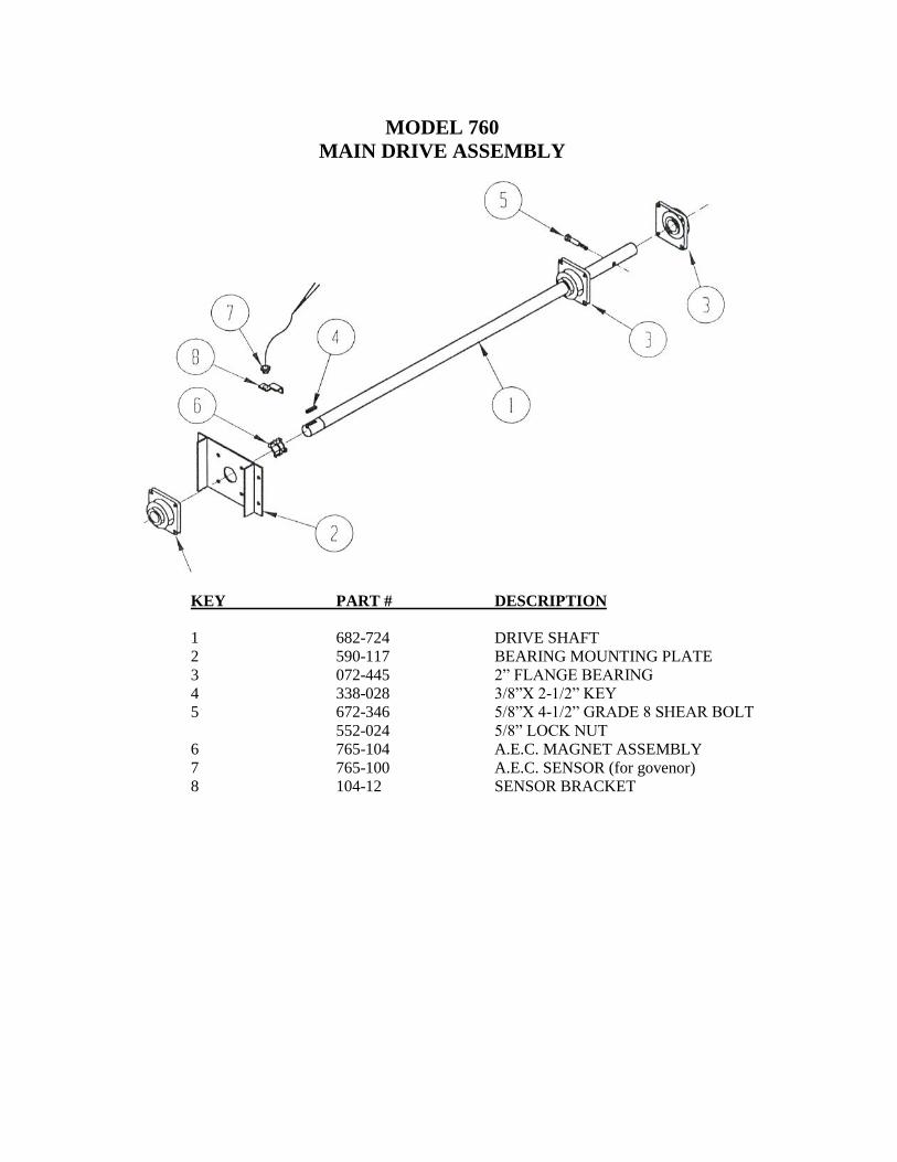
MODEL 760
MAIN DRIVE ASSEMBLY
KEY PART # DESCRIPTION
1 682-724 DRIVE SHAFT
2 590-117 BEARING MOUNTING PLATE
3 072-445 2” FLANGE BEARING
4 338-028 3/8”X 2-1/2” KEY
5 672-346 5/8”X 4-1/2” GRADE 8 SHEAR BOLT
552-024 5/8” LOCK NUT
6 765-104 A.E.C. MAGNET ASSEMBLY
7 765-100 A.E.C. SENSOR (for govenor)
8 104-12 SENSOR BRACKET
3
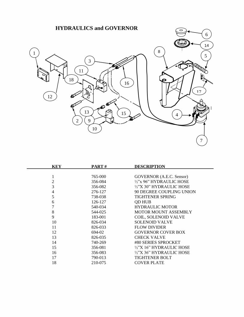
HYDRAULICS and GOVERNOR
KEY PART # DESCRIPTION
1 765-000 GOVERNOR (A.E.C. Sensor)
2 356-084 ½”x 96” HYDRAULIC HOSE
3 356-082 ½”X 30” HYDRAULIC HOSE
4 276-127 90 DEGREE COUPLING UNION
5 738-038 TIGHTENER SPRING
6 126-127 QD HUB
7 540-034 HYDRAULIC MOTOR
8 544-025 MOTOR MOUNT ASSEMBLY
9 183-001 COIL, SOLENOID VALVE
10 826-034 SOLENOID VALVE
11 826-033 FLOW DIVIDER
12 694-02 GOVERNOR COVER BOX
13 826-035 CHECK VALVE
14 740-269 #80 SERIES SPROCKET
15 356-081 ½”X 16” HYDRAULIC HOSE
16 356-083 ½”X 36” HYDRAULIC HOSE
17 790-013 TIGHTENER BOLT
18 210-075 COVER PLATE
14
6
5
17
4
7
8 1
3
2 9
12
11
18
13
10
15
16
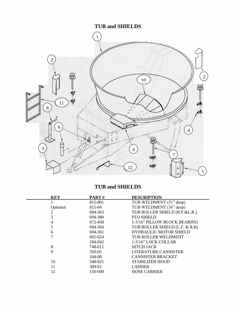
TUB and SHIELDS
TUB and SHIELDS
KEY PART # DESCRIPTION
1 815-001 TUB WELDMENT (51” deep)
Optional 815-04 TUB WELDMENT (36” deep)
2 694-363 TUB ROLLER SHIELD (R.F.&L.R.)
3 694-380 PTO SHIELD
4 072-458 1-3/16” PILLOW BLOCK BEARING
5 694-364 TUB ROLLER SHIELD (L.F. & R.R)
6 694-361 HYDRAULIC MOTOR SHIELD
7 682-654 TUB ROLLER WELDMENT
184-042 1-3/16” LOCK COLLAR
8 748-011 HITCH JACK
9 350-05 LITERATURE CANNISTER
104-08 CANNISTER BRACKET
10 348-021 STABILIZER HOOD
11 389-01 LADDER
12 150-008 HOSE CARRIER
1
6
4
10
2
11 8
9
3
12
7
5
2

MODEL 760 ROTOR ASSEMBLY
KEY PART # DESCRIPTION 1 642-055 SNAP RING
2 724-214 HAMMER SPACER (10 gauge)
126-058 THIN HAMMER SPACER
3 580-207 HAMMER PIN
4 656-068 ROTOR WELDMENT
5 328-001HS STANDARD HAMMER (hard faced)
6 328-003H LEAD HAMMER (hard faced & case hardened)
7 Optional 328-006 ALFALFA HAMMER
8 Optional 580-101 HAMMER LOCKING PIN ASSEMBLY
1
5 8
7
6
3 2
4

WHEEL AND HUB ASSEMBLY
WHEEL and HUB ASSEMBLY
KEY PART # DESCRIPTION
1 640-02 WHEEL RIM (15”x 6” 6 hole)
2 910-259 OUTER WHEEL BEARING
3 552-06 LUG NUT (1/2”x 20 UNF)
4 909-905 DUST CAP, HUB
5 280-551 HUB, 6 BOLT W/ CUPS
6 280-720 SPINDLE, WHEEL
7 910-264 CONE, INNER BEARING
8 906-284 SEAL, GREASE
9 552-030 CASTLE NUT, 7/8”x 14 UNF
10 800-020 RADIAL TIRE, P235/70R15
6
5
3
9
10
1

STANDARD SPOUT ASSEMBLY (Including Extension, Short Discharge, & Bunk Feeder Spout)
KEY PART # DESCRIPTION 1 348-02 DEFLECTOR HOOD
2 126-121 BUSHING
3 706-01 PULLEY
4 738-01 SPRING
5 348-01 UPPER HOOD
6 222-02 CYLINDER, HYDRAULIC 2” x 4’ STROKE
7 734-06 SPOUT, LOWER HALF
8 126-121 BUSHING
9 210-04 CHUTE COVER
10 136-01 COIL CHAIN, ¼ x 12’
11 130-01 CABLE, 1/8 x 60
12 222-03 CYLINDER EAR
13 036-04 CYLINDER STRAP
14 580-01 CYLINDER STRAP PIN
15 734-050 SPOUT SWIVEL ASSEMBLY
16 734-11 SHORT DISCHARGE
734-07H SHORT DISCHARGE with HYD ATTACHMENTS
17 348-11 DEFLECTOR HOOD
18 257-02 2 ft SPOUT EXTENSION
19 210-081 EXTENSION COVER
20 330-014 EXTENSION HANDLE EXTENSION
21 356-080 ¼”x 16’ HYDRAULIC HOSE
22 350-001 BUNK FEEDER SPOUT
23 348-12 BUNK FEEDER DEFLECTOR HOOD
2 Foot Spout Extension
Bunk Feeder
Short Discharge Spout

PTO DRIVE LINE ASSEMBLY
PTO DRIVE LINE ASSEMBLY
Walterscheid brand from S.N. 1400097 & higher
SHEAR BOLT YOKE
KEY PART # DESCRIPTION 1 362430 SLIDE YOKE, TRACTOR, 1 3/8 - 21 SPLINED
362428 SLIDE YOKE, TRACTOR, 1 3/8 – 6 SPLINED
362434 SLIDE YOKE, TRACTOR, 1 ¾ - 20 SPLINED
2 312209 CROSS & BEARING KIT
3 391294 YOKE & BAR WLD. INBOARD
4 391295 YOKE, SLEEVE & TUBE, WLD. INBOARD
5 391809 CLUTCH, SHEAR BOLT
6 365387 CONE, SHIELD 7 RIB
7 87276 BEARING RING, SC25/I
8 391434 SHIELD TUBE, OUTER
9 391433 SHIELD TUBE, INNER
10 365305 SCREW
11 383333 DECAL, OUTER
12 383334 DECAL, INNER
13 364915 REPAIR KIT, COLLAR
14 10490 LOCK NUT, M12
15 20466 BOLT, M12 x 60 – 8.8
16 391296 COMPLETE W2500 SERIES PTO W/ 1 3/8 – 21
SPLINE TRACTOR SLIDE YOKE & 1 15/16
IMPLEMENT SHEAR YOKE.
11
8
6
1
14
3
2
13
2
16 9
5
10 6
4
7
15
12
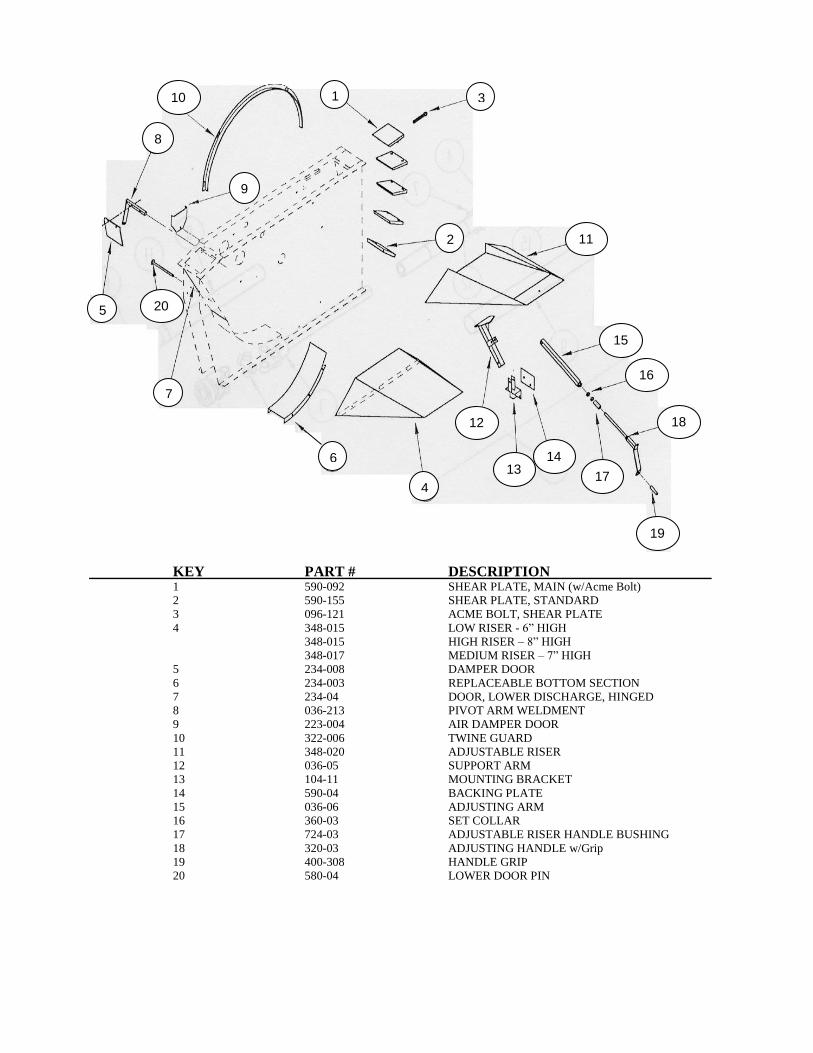
MILL HOUSING PARTS AND ACCESSORIES
KEY PART # DESCRIPTION 1 590-092 SHEAR PLATE, MAIN (w/Acme Bolt)
2 590-155 SHEAR PLATE, STANDARD
3 096-121 ACME BOLT, SHEAR PLATE
4 348-015 LOW RISER - 6” HIGH
348-015 HIGH RISER – 8” HIGH
348-017 MEDIUM RISER – 7” HIGH
5 234-008 DAMPER DOOR
6 234-003 REPLACEABLE BOTTOM SECTION
7 234-04 DOOR, LOWER DISCHARGE, HINGED
8 036-213 PIVOT ARM WELDMENT
9 223-004 AIR DAMPER DOOR
10 322-006 TWINE GUARD
11 348-020 ADJUSTABLE RISER
12 036-05 SUPPORT ARM
13 104-11 MOUNTING BRACKET
14 590-04 BACKING PLATE
15 036-06 ADJUSTING ARM
16 360-03 SET COLLAR
17 724-03 ADJUSTABLE RISER HANDLE BUSHING
18 320-03 ADJUSTING HANDLE w/Grip
19 400-308 HANDLE GRIP
20 580-04 LOWER DOOR PIN
1
3
10
8
9
5
7
20
11
15
16
18
19
17
14 13
12
2
6
4

CORN AND GRAIN ATTACHMENT
KEY PART # DESCRIPTION
1 348-05 SHELL CORN HOOD 2 348-06 FILL CHUTE 3 234-03 GATE
4 580-02 GATE PIN
5 348-019 GRAIN HOOD
6 590-155 SHEAR PLATE 7 215-260 EAR CORN SHIELD
8 215-240 SHIELD SUPPORT
4
3
1
2
5
6
8 7

TUB AND TUB OPTIONAL EQUIPMENT KEY PART# DESCRIPTION 1 815-001 STANDARD TUB ASSEMBLY (51” Deep) 1 Optional 815-04 SHORT TUB ASSEMBLY (36” Deep) 2 Optional 014-001 ROUND BALE ASSIST 3 Optional 815-003 TUB FLARE EXTENSION (not shown) Fits tall tub only, when installed overall width is
11’-3” and adds 8” to the height.
22

DELIVERY SERVICE FOR ROTO GRIND This form must be filled out by the dealer and signed by both the dealer and the customer at the time of delivery.
Delivered to: Dealer
R.R. No. Box No. Town State Town Phone Serial
State Zip Product
I have thoroughly instructed the buyer on the above described equipment which review included the Operator’s Manual content, equipment care, adjustments, and safe
operation. The warranty policy provisions were also explained and reviewed.
DEALER’S SIGNATURE Above equipment and Operator’s Manual have been received by me and I have been thoroughly instructed as to care, adjustments, safe operation, and applicable warranty policy.
DATE OWNERS SIGNATURE
CUSTOMER COPY
DELIVERY SERVICE FOR ROTO GRIND This form must be filled out by the dealer and signed by both the dealer and the customer at the time of delivery.
Delivered to: Dealer
R.R. No. Box No. Town State Town Phone Serial
State Zip Product
I have thoroughly instructed the buyer on the above described equipment which review included the Operator’s Manual content, equipment care, adjustments, and safe
operation. The warranty policy provisions were also explained and reviewed.
DEALER’S SIGNATURE Above equipment and Operator’s Manual have been received by me and I have been thoroughly instructed as to care, adjustments, safe operation, and applicable warranty policy.
DATE OWNERS SIGNATURE
MANUFACTURER COPY
DELIVERY SERVICE FOR ROTO GRIND This form must be filled out by the dealer and signed by both the dealer and the customer at the time of delivery.
Delivered to: Dealer
R.R. No. Box No. Town State
Town Phone Serial State Zip Product
I have thoroughly instructed the buyer on the above described equipment which review included the Operator’s Manual content, equipment care, adjustments, and safe
operation. The warranty policy provisions were also explained and reviewed.
DEALER’S SIGNATURE Above equipment and Operator’s Manual have been received by me and I have been thoroughly instructed as to care, adjustments, safe operation, and applicable warranty policy.
DATE OWNERS SIGNATURE
DEALER COPY