optical 3d coordinate measuring machine
TRANSCRIPT
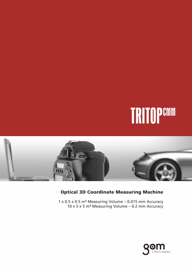
Optical 3D Coordinate Measuring Machine
1 x 0.5 x 0.5 m³ Measuring Volume – 0.015 mm Accuracy10 x 5 x 5 m³ Measuring Volume – 0.2 mm Accuracy

Industrial Measurement TechnologyQuality Control and 3D Inspection
The portable TRITOPCMM system measures coordinates of three-dimensional objects quickly and precisely. Measuring tasks that traditionally were performed by tactile 3D coordinate measuring machines can now easily be carried out with the TRITOPCMM system. It does not require any complex, heavy and maintenance-intensive hardware. The measuring machine comes to the object!
As with tactile coordinate measuring machines TRITOPCMM records the coordinates and their orientation in space for any feature of interest:
• Surface points and sections• Primitives• Holes, punch holes and edges• Diameters, lengths, angles …
After the 3D coordinates have been determined, the measurement mathematically is transformed into the coordinate system of the component:
• RPS• Gage alignment• Best-fit…
The measured and aligned data is used for various tasks:
• CAD comparison • Verificationofshapeandpositiontolerances• Verificationofspecificationsfromdrawings, filesortables• Initial measurements
When comparing the measuring data with CAD data (IGES, VDA, STEP, Catia, ProE, UG …), the corresponding measuring reports are created in the familiar formats:
• False-color representation• Deviation of individual points as labels• Sections, angles and distances• Diametersandflatness• Tables and lists
Optical 3D Coordinate Measuring Machine

Image Processing with Subpixel AccuracyThe Mouse Pointer Becomes a Touch Probe
The measuring object is recorded with a high-resolution digital camera. The images are automatically evaluated on a notebook using the TRITOPCMM software. With a mathematical adjustment computation, a precise model is automatically calculated from ray intersections, camera positions, lens distortions and object coordinates. The adhesive reference point markers applied to the object and the coded markers and scale bars placed next to the object are included in this computation.
Based on this model and on the digital images, the user performs the actual measurement directly on the notebook screen. He clicks with the mouse pointer on the features to be measured and thus starts a newtypeofimageprocessingandtriangulationalgorithms.Thesoftwarethenfitstheseselectedfeatures three-dimensionally in space and automatically decides which images are suitable for the exact coordinate determination.
It only takes seconds to determine features like surface control points, sections, holes etc. without occupying the object any longer.
A 3D object window shows all measured features and coordinates. In this window, CAD data is imported, best-fitelementslikecylinders,conesetc.arecreatedandsimpleCADfunctionslikeintersectionsandprojections are used. Any combination of elements is possible. The user has direct access to dimensions like distances, angles or diameters.
Deviations to the CAD data are displayed in false-color. Automatic or interactive labels or sections display the numerical values of the deviations. Finally, the measuring reports are exported or directly printed.

Measuring with Photos As for all 3D measurements, the object for a TRITOPCMM measurement has to beinastableandfixedpositionaswell.
Prior to taking photos, the object needs to be prepared:
• Somecodedmeasuringmarkersareappliedtothefixtureordirectlyto the object. These markers are used for the fully automatic evaluation process.• Scale bars are positioned next to the object. Their dimensions are transferred to the measurement. Two scale bars are used to observe the measuring accuracy.• Surface points to be measured have to be marked. For this purpose, adhesive points can be used, the thickness of which is precisely known. Another method is to mark points or sections with a pen. Each point or line drawn like this is precisely determined by image processing algorithms.
In order to carry out TRITOPCMM measurements, the object needs to be recorded from various directions with the digital camera. It is not necessary to maintain exact camera positions. A rough scheme of recording positions for certain objects is shown in the user manual.
The camera images are transferred to the notebook fully automatically using ahigh-speedwirelessnetworkoraflashcardreader.Onthenotebook,thecomplete further evaluation is carried out.
Idea of the TRITOPCMM Technique• The system precisely determines the coordinates of each adhesive reference point and each freehand marking. Thus, these coordinates describe a point on the object‘s surface. As with tactile machines, here as well several individual points are combined to primitives, or the deviation to the nominal surface is directly determined.
Advantages of the TRITOPCMM Technique• Complete 3D measuring machine with minimum hardware requirements (2 cases with a total weight of 23 kg)• The object is not touched during measuring• Very high accuracy also for large objects• No wear and tear, no decrease of accuracy• Easy handling• Independent of environmental conditions (climatic chamber, open air …)
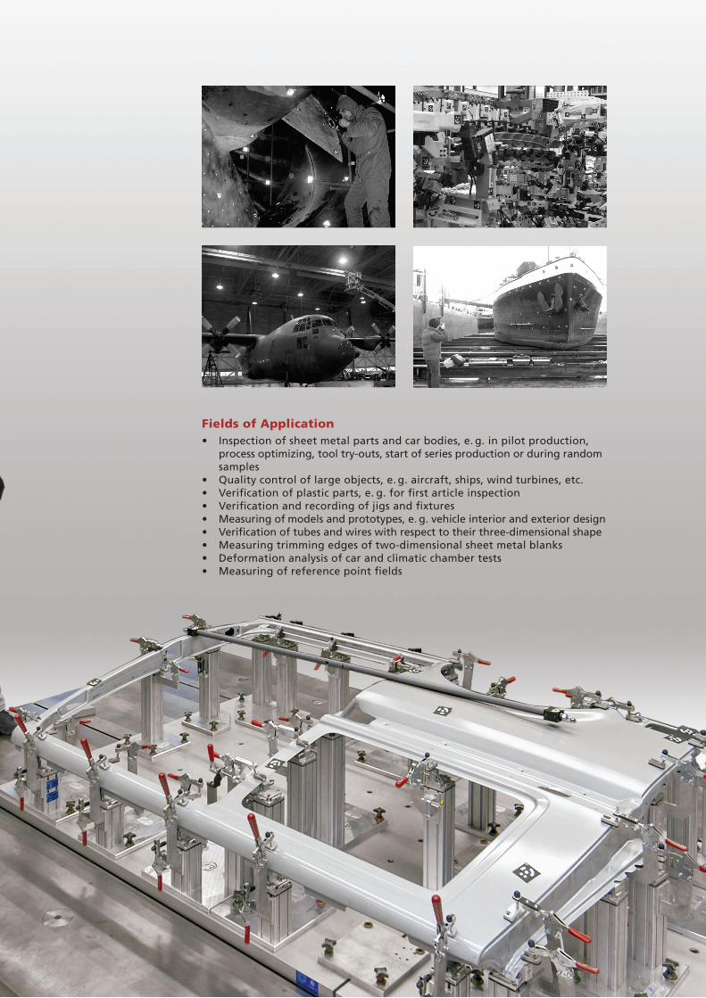
Fields of Application• Inspection of sheet metal parts and car bodies, e. g. in pilot production, process optimizing, tool try-outs, start of series production or during random samples• Quality control of large objects, e. g. aircraft, ships, wind turbines, etc.• Verificationofplasticparts,e.g.forfirstarticleinspection• Verificationandrecordingofjigsandfixtures• Measuring of models and prototypes, e. g. vehicle interior and exterior design• Verificationoftubesandwireswithrespecttotheirthree-dimensionalshape• Measuring trimming edges of two-dimensional sheet metal blanks• Deformation analysis of car and climatic chamber tests• Measuringofreferencepointfields

The Complete TRITOPCMM System
Measuring Camera • Digital camera with high-resolution CCD chip• Stableandcertifiedlens• Datatransmissionviaflashcardornetwork• Flash• Robust plastic case for camera and notebook
High-speed Wireless Network• Fast, wireless 54Mbit/s image transfer• 64 bit encryption• Automatic analysis of the measurement images
Notebook • High-performance notebook with OpenGL graphics• Networkcardandflashcardreader• DVD/CD recorder/reader• Windows and LINUX installation
Scale Bars• Low thermal expansion• 4 x 1 m and 2 x 0.5 m, screwable (gage block principle)• Various inserts for different object sizes• CertifiedlengthaccordingtoGermanand American standards• Codedforautomaticidentification• Robust plastic case
Marker Material• Coded points on adhesive or magnetic foil• Adhesive points of various sizes• Marker pens• Adapter for threads, setscrews and collar holes
Software• Loading of digital color and gray scale images• Robust orientation of image sets• Precise online calibration of cameras and lenses• Bundle adjustment with an unlimited number of unknowns • Feature and surface oriented image processing• Macro functionality for process automation• Mathematical alignment of components• Nominal/actual comparison with CAD interface• Primitive module• Measuring reports in various formats
System Description
• Non-contact photogrammetry system• Self-calibrating due to overdetermined systems of equations• Self-checking due to the use of two scale bars• Maintenance-free• Typical measuring time per object: 5 to 60 minutes (depending on the object size)• Typical number of measuring points per object: 10 to 50,000• CAD interface (IGES, VDA, STEP, Catia, ProE, UG …)• Average length measurement deviation according to VDI/VDE 2634 [µm]: 5 + L/50 (L in mm)• Temperature range without camera protection: 0° to 50° C• Temperature range with camera protection: -40° to 100° C• Humidity: non-condensing• Case size: 1350 x 260 x 120 mm³ and 470 x 390 x 190 mm³• Total weight: 23 kg
GOM
GOM was founded in 1990 as spin-off of the Technical University Braunschweig, Germany. The company owns subsidiaries in Switzerland, France, Great Britain, Italy and Belgium. Worldwide, more than 40 committed and competent partners market GOM products.
GOMfocusesonthedevelopmentofoptical3Dmeasurementtechnologyforindustrialuse.Efficientmeasuring instruments are available for numerous applications. The equipment is mainly used in product development and quality assurance.
Today, GOM employs more than 250 people and can rely on the support of their international distributors.

Co
pyr
igh
t ©
201
2 G
OM
mb
H
A
ll r
igh
ts r
eser
ved
!
Rev
. G
(en
) 28
1013