over current & earth fault setting calculations
DESCRIPTION
Training Electrical protectionTRANSCRIPT

Slide 1
6th Comprehensive Protection Training Programat Pearl Continental L AHORE in 2012
A TYPICAL POWER SYSTEM NETWORK

Slide 2
SIEMENSLECTURE ON
OVER CURRENT & EARTH FAULT RELAY SETTING CALCULATIONS
AT
PEARL CONTINENTAL HOTEL LAHORE
ON 04-09-2012
BYSIEMENS PAKISTAN ENGINEERING COMPANY
LTD

Slide 3
RELAY SETTING CALCULATIONS
A guide for the calculations of the Relay Settings for:
Over current and Earth fault Relaysa) Definite Time Relaysb) Inverse Time RelaysFor Power Transformers & 11kv feeders

Slide 4
RELAY SETTING CALCULATIONS1. Enlist the technical data required in network study and
calculations of relay settings.2. Ask from client\consultant to provide essential technical data
relating to the existing network and equipment needed in the subject matter.
3. Study carefully the protection schemes designed for the project.
4. Enlist the protection relays with their functions to be used.
5. Chalk out which type of documents are agreed to submit to consultant/client.
6. Arrange the content/index sheet of the relays, need to settings' calculations.
7. Submission of proposed relay settings to the consultant\client for approval.
8. Arrange a meeting to clarify technical and disputed pointsregarding to the submitted document for the approval.
9. Finalize the relays setting calculations with duly signed from client\consultant\contractor.
10.Upload the parameters in the relays according to the calculations at site for pre-commissioning and testing.

Slide 5
RELAY SETTING CALCULATIONS
Please note that
- Minimum generation is considered for relay setting calculations. (pick up,trip)
&
- Circuit Breaking capacity is calculated for maximum generation possible.

Slide 6 PAKISTAN
G
G
1 2
34POWER HOUSE STATION A
132 kVSTATION B 132 kV
Boundary of Protection Zones are decided by Location of CT’sX Circuit Breaker
1 Generator Protection Zone
2 Generator Transformer Unit Protection Zone
3 Bus Bar Protection Zone
4 Transmission Line Protection Zone
PROTECTION IN SMALL ZONESUSING OVERLAPPING PRINCIPLE

Slide 7
Slide 8
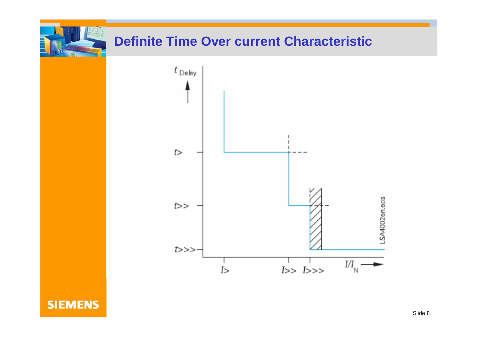
Definite Time Over current Characteristic
Slide 9
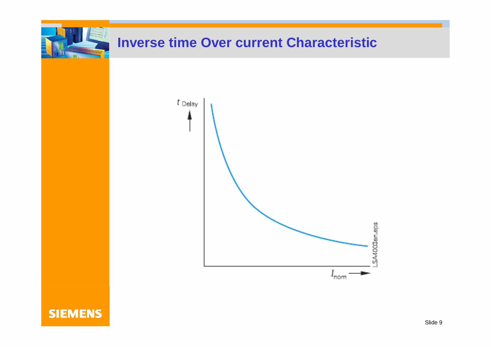
Inverse time Over current Characteristic

Slide 10

Slide 11
Normal Inverse time characteristic of relay 7SJ60

Slide 12
SETTING DEFINITE TIME OVERCURRENTRELAYS
Over current Relays has a wide range of applications. It can be applied where there is an abrupt change of current due to faultycondition.These relays are used for protection of Motors, Transformers, Generators and Transmission Lines etc. In distribution networks these are the main protection whereas in HV and EHV systems, these are used as back up protection. Although there is no hard and fast rule for use of definite time or inverse time relays and one can decide by looking into the site requirements.
NTDC and the utilities in Pakistan however have standard practice to use Inverse time relays for back up of Motors, Transformers and Generators. For HV and EHV lines, definite time over current relays are used for back up purpose.

Slide 13
SETTING DEFINITE TIME OVERCURRENTRELAYS
Definite time over current relays have adjustable over current elements. When an element picks up, it energizes a built in time element which initiates a tripping signal after elapse of set time. In definite time over current Relays, we have to set,
The over current element for its pick up value, the high set element for its pick up value along with the time delays required.
The instantaneous element pick up value for the current is to be selected whereas time setting is instantaneous.

Slide 14
7SJ602 SETTING POSSIBILITIES
OVERCURRENT RELAY 7SJ602
PHASE FAULTS EARTH FAULTS
STAGE I> DEFINITE TIME DEFINITE TIME OR OR IDMTL IDMTL
STAGE I>> DEFINITE TIME DEFINITE TIMEOR OR INSTANTANEOUS INSTANTANEOUS
STAGE I>>> INSTANTANEOUS - - - - - - - - - - - -

Slide 15
OVERCURRENT RELAY SETTINGS

Slide 16
OVERCURRENT RELAY SETTINGS
The relay at the far end B is set with shortest operating time. The Relay on upstream which is at end A has to be time graded against relay at end B with a minimum time difference of 200-300mSec for numerical relays and of 400-500mSec for electro-mechanical relays.
The relay at end B is required to be set with the minimum operating time IDMTL mode and to be set for TMS of 0.1or 0.05 Time Dial whichever setting is available. The relay at end A has to be set accordingly.
Slide 17
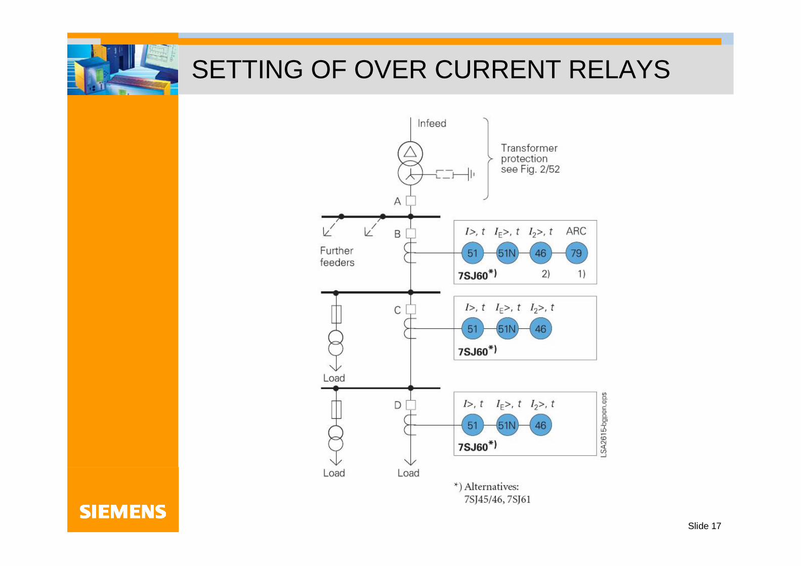
SETTING OF OVER CURRENT RELAYS
Slide 18
OVERCURRENT RELAY SETTINGSIn the previous diagram, the relay at far end (D) is set with shortest operating time. Relays on the upstream are to be time graded against the next down stream relay in steps of 0.2 Secs.
Definite time characteristic is selected where Source Impedance is quite larger compared to the line impedance. This means small current variation between near and far end faults.
The inverse mode is selected where fault current is much less at the far end of the line than at the local end.(Selection also depends on the utility preference looking into their operational requirements.)

Slide 19
7SJ602 SETTING CALCULATIONS FOR AUTOTRANSFORMER 3x200 MVA 500KV3 × 200 MVA Auto-transformer HV Winding CircuitTime Over Current Relay Type: 7SJ6021-5EB20-1FA0
CT Ratio : N = 3250/1Rated power: S = 600MVARated voltage: (at minimum tap) U = 472.5KVRequired Settings:
Plug SettingCharacteristic to be selectedTime Multiplier Setting (TMS)High Set Element Settings, I >> Instantaneous Element Setting, I >>>
Plug Setting:Autotransformer HV winding rated current IN = S ÷ ( 3 × U ) IN = 733AAllowed overloading = 5%Relay's resetting ratio = Drop off ÷ Pick up R = 0.95Relay's setting current = (IN + IN ) ÷ R Is = 810ACorresponding secondary current = Is ÷ N = 0.25A

Slide 20
7SJ602 SETTING CALCULATIONS FOR AUTOTRANSFORMER 3x200 MVA 500KV
Characteristic to be selected:Normal Inverse Characteristic is selected according to the NTDC System practice.
Usually for inductive loads, inverse time characteristics are selected.For line feeders, definite time characteristics are suggested.
Time Multiplier Setting:Fault current at HV Connection of autotransformer IF =11548AMultiples of Fault Current (PSM) = IF ÷ Is =14.25As per IEC Normal Inverse characteristic =0.14÷{(14.25)0.02-1}Operating time at TMS = 1 A =2.565 sec.For selectivity as backup, tripping time chosen B =1.200 sec.Required time multiplier setting, = B ÷ A TMS = 0.47
High Set Element setting = to be blockedInstantaneous setting (Ipick up = 5 × IN ) =5.00 I/In
Settings recommended:Over current plug setting =0.25 I/InTMS setting =0.47Characteristic = Normal InverseInstantaneous setting (Ipick up = 5 × IN ) =5.00 I/InHigh Set Element Settings, I >> IE >> = Blocked

Slide 21
7SJ602 SETTING CALCULATIONS FOR AUTOTRANSFORMER 3x200 MVA 500KV3 × 200 MVA Auto-transformer HV Winding CircuitEarth Fault Time Over Current Relay Type: 7SJ6021-5EB20-1FA0CT Ratio : N = 3250/1Rated power: S = 600MVARated voltage: (at minimum tap) U = 472.5KVRequired Settings:
Plug SettingCharacteristic to be selectedTime Multiplier Setting (TMS)High Set Element Settings, IE >>Instantaneous Element Setting, IE >>>
Plug Setting: Autotransformer HV winding rated current IN = S ÷ 3 × U ) IN = 733AMinimum fault current considered as percentage of rated current = 5%
(for purpose of pick up of relay)Relay's resetting ratio = Drop off ÷ Pick up R = 0.95Relay's setting current = ( )×(IN ÷ R) =.05x733 ÷.95=38.57 or Is = 39ACorresponding secondary current = Is ÷ N = 0.01A
Slide 22
7SJ602 SETTING CALCULATIONS FOR AUTOTRANSFORMER 3x200 MVA 500KV
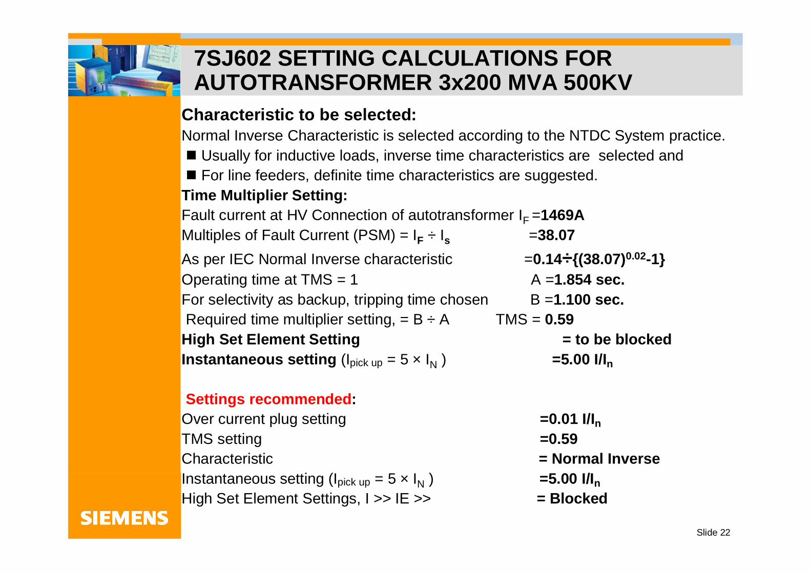
Characteristic to be selected:Normal Inverse Characteristic is selected according to the NTDC System practice.
Usually for inductive loads, inverse time characteristics are selected andFor line feeders, definite time characteristics are suggested.
Time Multiplier Setting:Fault current at HV Connection of autotransformer IF =1469AMultiples of Fault Current (PSM) = IF ÷ Is =38.07As per IEC Normal Inverse characteristic =0.14÷{(38.07)0.02-1}Operating time at TMS = 1 A =1.854 sec.For selectivity as backup, tripping time chosen B =1.100 sec.Required time multiplier setting, = B ÷ A TMS = 0.59
High Set Element Setting = to be blockedInstantaneous setting (Ipick up = 5 × IN ) =5.00 I/In
Settings recommended:Over current plug setting =0.01 I/InTMS setting =0.59Characteristic = Normal InverseInstantaneous setting (Ipick up = 5 × IN ) =5.00 I/InHigh Set Element Settings, I >> IE >> = Blocked
Slide 23
OVER CURRENT RELAY SETTINGS FOR 11KV FEEDER
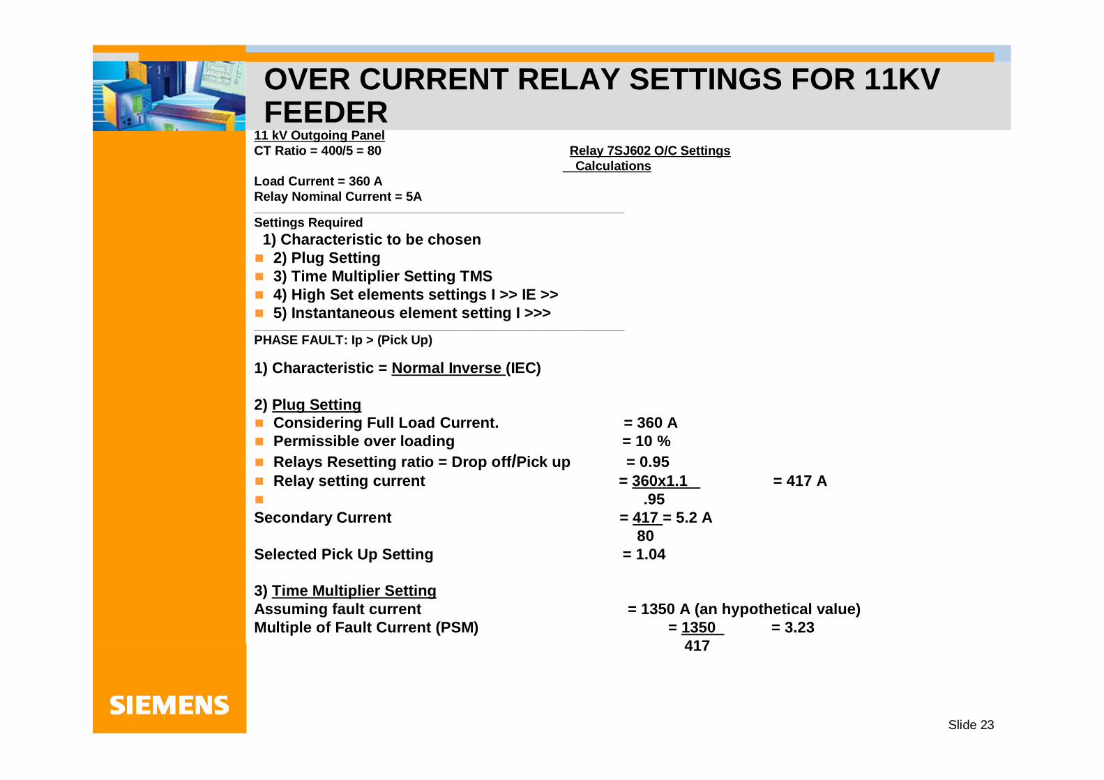
11 kV Outgoing PanelCT Ratio = 400/5 = 80 Relay 7SJ602 O/C Settings
Calculations Load Current = 360 A Relay Nominal Current = 5A___________________________________________________________________________ Settings Required
1) Characteristic to be chosen 2) Plug Setting3) Time Multiplier Setting TMS 4) High Set elements settings I >> IE >> 5) Instantaneous element setting I >>>
___________________________________________________________________________ PHASE FAULT: Ip > (Pick Up)
1) Characteristic = Normal Inverse (IEC)
2) Plug Setting Considering Full Load Current. = 360 A Permissible over loading = 10 % Relays Resetting ratio = Drop off/Pick up = 0.95 Relay setting current = 360x1.1 = 417 A
.95 Secondary Current = 417 = 5.2 A
80 Selected Pick Up Setting = 1.04
3) Time Multiplier Setting Assuming fault current = 1350 A (an hypothetical value)Multiple of Fault Current (PSM) = 1350 = 3.23
417

Slide 24
OVER CURRENT RELAY SETTINGS FOR 11KV FEEDER (continues)
Operating time as per IEC NI Characteristics = 0.14 = 0.14 = 5.24
(3.23 0.02 – 1) 0.0267
Time required for Relay Operation is = 300 mSec ( Normally site requirements should be considered. )
Therefore: TMS = _0.3_ = 0.057 5.24
PHASE FAULT: Ip >> (High Set)1) Characteristic = Definite Time _2) Plug Setting
Considering 4.0 times the Pick up Current. Secondary Current = 1668 = 20.85 A
80(ct ratio) Selected Pick Up Setting = 20.85/ 5 =4.17 3) Time Setting
= 0.1 s (to be chosen by the engineer as per requirement)PHASE FAULT: Ip>>> (Instantaneous)1) Characteristic = Instantaneous 2) Plug Setting
Considering 5.0 times the Pick up Current. Secondary Current = 417x5 = 26.05 A
80 Selected Pick Up Setting = 26.05/5 = 5.2 (or we can calculate from I pick up which will be 1.04 x 5 = 5.20)(Please note that the fault current is to be calculated based on fault calculation study on HT side and considering the secondary impedance of the Transformer installed )

Slide 25
EARTH FAULT SETTINGS FOR 11KV FEEDER
Relay 7SJ602 E/F Settings Calculations
EARTH FAULT: Ie> (Pick Up) CHARACTERISTIC SELECTED = NORMAL INVERSE (IEC)Plug Setting
Considering NTDC practice to set the E/F element pick up at 20% of ct sec. rated current. = 0.2 x 5 = 1 (effective value in amps = 80 Amps)(Utilities normally select earth fault element pick up from 10% to 20%. At lower pick up values, sensitivity increases and stability reduces. At higher pick up, the sensitivity is reduced but stability is increased. Normally time of operation is set equal to phase operation time.)
Time Multiplier SettingAssuming single phase to ground fault current = 650 AmpsMultiple of Fault Current = 650 = 7.71
84.2 Operating time as per IEC NI Characteristics = 0.14 = 0.14 = 3.365
(7.71 0.02 – 1) 0.0416

Slide 26
EARTH FAULT SETTINGS FOR 11KV FEEDER
Time required for Relay Operation is = 0.3 Sec ( to be selected considering site
conditions) Therefore: TMS = 0.3 = 0.089
3.365
EARTH FAULT: Ie>> (Instantaneous element setting) 1) Characteristic = Instantaneous 2) Plug Setting
Considering fault Current = 650A = 650 = 8.125
80 Pick Up Setting for instantaneous element = 8.125/5=1.625 (It is to be noted that settings are selected keeping in view the site conditions and past experience. No hard and fast rules can be chalked out. These examples are to show the procedure only. )

Slide 27
Thank you for your Attention

Slide 28
CONSTRUCTION OF ELECTRO-MECHANICAL RELAYS

Slide 29
Protection Co ordination of inverse time relays &Disc emulation
Disc emulation evokes a dropout process,which begins after de energization. ThisProcess corresponds to the back turn ofa Ferraris Disc. In case several faults o-ccur successively, it is ensured that dueto the inertia of the Ferraris Disc, the h-
istory is taken into consideration.
Consider the main over current relay of electro mechanical type and the feeder relay of numerical type. There are chances that the Main relay may operate unnecessarily on repeated feeder fault.To avoid this Disc emulation feature is introduced.The Disc emulation feature Offers its advantages when the grading co ordination chart of the time over current protection is combined with other devices(elect. Mech or induction base) connected to the system.

Slide 30
SLAVE POINTER AND MEAN VALUES
Slave pointer and Mean values is basically a measuring technique to measure the Maximum , Minimum and average values of waveform. The waveform can be of current or voltage.

Slide 31
THERMAL OVER LOAD PROTECTIONThe thermal Over load protection prevents the protected object (cables, motors and transformers etc) from damage caused by thermal over loading. This protection operates independent on the time over current and unbalanced load protection. It can work with memory or without memory.OVER LOAD PROTECTION WITHOUT MEMORYIf the overload protection without memory is selected, the tripping time is calculated according to a formula. When the current in any phase exceeds threshold value, timer picks up. Trip command is given after the time has elapsed. This method is easy in handling.
t= 35x tL(I/ IL )2 - 1
wheret is tripping timeI is over load currentIL parameterized threshold valuetL parameterized time multiplier
(tripping time with 6 times thethreshold value IL)

Slide 32
THERMAL OVER LOAD PROTECTION
OVER LOAD PROTECTION WITH MEMORY
The unit computes the temperature rise according to a thermal single body model (thermal replica). This method requires some knowledge of the protected object, its ambient context and its cooling temperature etc.This method is used when the object is to be operated at the limit of its performance.

Slide 33
CONCEPT OF I/ININ is the rated current of the relay and also the secondary current of the Current Transformer. They should match with each other sothat correct setting and pick up values could be selected. Example: In the 7SJ602 relay, the phase current pick up I range has been defined as 0.1 IN ------4.0 INIf IN is 1 amp then it is easy to understand that the pick up range will be from 0.1 amp to 4.0 ampHowever if IN is 5 amp then the pick up range will be from 0.5 to 20 amps To make it simpler we can write the above pick up range as
I/ IN from 0.1 to 4.0(10% to 400%)This statement is independent of amps. We have to always look atI/IN and set the relay from 0.1 to 4.0Assume ct 100/1,relay rated current 1, the relay pick up set at 1 means relay will pick up at 100 Amps in primaryAnd if we assume ct of 100/5, relay rated current 5, the relay pick up set at 1 means that relay will pick up at 100 Amps(ct 100/5 relay 1 amp- relay pick up setting possible 2 to 80 Amp)(100/5 means 20 relay can be set 20 x 0.1-4.0 i.e. 2-80 Amps)