overhead transmission lines suspension and … · these guidelines describe ... ance with tr 05-04e...
TRANSCRIPT
SvK4
005E
, v3.
0, 2
012-
08-0
9
UNIT, BUSINESS AREA OUR REFERENCE AFL, Asset Management Lines TR05-05E
DATE CONSULTATIONS 2016-06-09 NT TECHNICAL GUIDELINE
REVISION APPROVED 4 Td
Overhead transmission lines Suspension and support clamps
Introduction This English text is to be regarded as a translation of the Swedish guideline. The Swe-
dish text and the interpretation thereof shall govern the contract and the legal rela-
tions between parties.
These guidelines describe the requirements on suspension and support clamps for use
on steel reinforced aluminium conductors and aluminium alloy conductors in accord-
ance with TR 05-04E for overhead transmission lines and cover design and inspection.
The guidelines intend to guarantee satisfactory performance of suspension and sup-
port clamp during the lifetime of the overhead line and shall be used at purchasing of
suspension and support clamp.
TEKNISK RIKTLINJE 2016-06-09 TR05-05E utg 4
1 (24)

Notes Change notes Date
1 (A) New template, Table 1 revised. Clause 5.12 inserted. 09 / 07 / 2008
2 New template. Clause 5.4.2, 5.1.1, 5.5.3.5, 5.5.3.8, 5.8.2.1, 5.8.2.7 and 5.9 revised. Clause 5.8.4 added.
02 / 04 / 2012
3 New template.Chapter number revised. References updated and tolerances added in Table 1
20 / 05 / 2016
4 Misprint clause 6.8, clause 5.3.4 inserted 09 / 06 / 2016
TEKNISK RIKTLINJE 2016-06-09 TR05-05E utg 4
2 (24)

Content
1 References ................................................................................................................. 6
2 Scope .......................................................................................................................... 7
3 Definition ................................................................................................................... 7
4 Description ............................................................................................................... 8
4.1 Suspension clamp ....................................................................................... 8 4.2 Support clamp ............................................................................................. 8 4.3 Counterweight stirrup ................................................................................ 8
5 Requirements ........................................................................................................... 8
5.1 General ........................................................................................................ 8 5.2 Material ........................................................................................................ 9
5.2.1 Body and keeper ............................................................................ 9 5.2.2 Bolts and nuts ................................................................................ 9 5.2.3 Washers ......................................................................................... 9 5.2.4 Threaded inserts ............................................................................ 9 5.2.5 Straps ............................................................................................. 9
5.3 Design ........................................................................................................... 9 5.3.1 Clamp ............................................................................................. 9 5.3.2 Conductor supporting groove ...................................................... 9 5.3.3 Fatigue damages ......................................................................... 10 5.3.4 Straps ........................................................................................... 10 5.3.5 Bolts and nuts .............................................................................. 10 5.3.6 Washers ....................................................................................... 10 5.3.7 Suspension clamps ...................................................................... 10 5.3.8 Support clamps ........................................................................... 10 5.3.9 Counterweight stirrups............................................................... 10 5.3.10 Marking ....................................................................................... 11
5.4 Mechanical requirements .......................................................................... 11 5.4.1 Suspension clamps for earth wire.............................................. 11 5.4.3 Support clamps for earth wire ................................................... 11
TEKNISK RIKTLINJE 2016-06-09 TR05-05E utg 4
3 (24)

5.4.4 Clamps ......................................................................................... 12 5.4.5 Clamping force ............................................................................ 12 5.4.6 Bolts and threads ........................................................................ 12 5.4.7 Counterweight stirrups............................................................... 12
5.5 Electrical requirements ............................................................................. 12 5.5.1 Fault current ................................................................................ 12 5.5.2 Corona .......................................................................................... 12 5.5.3 Hysteresis losses .......................................................................... 12
6 Type test ................................................................................................................... 13
6.1 General ....................................................................................................... 13 6.2 Dimensions ................................................................................................. 13 6.3 Thickness of zinc coating ........................................................................... 13 6.4 Hardness .................................................................................................... 13 6.5 Clamping force ........................................................................................... 13 6.6 Threads ....................................................................................................... 13 6.7 Permanent deformation ............................................................................ 14
6.7.1 Suspension and support clamp .................................................. 14 6.7.2 Counterweight stirrup ................................................................ 14
6.8 Breaking load ............................................................................................. 14 6.9 Corona ........................................................................................................ 15 6.10 Fault current .............................................................................................. 15
7 Sample test .............................................................................................................. 15
7.1 General ....................................................................................................... 15 7.2 Dimensions ................................................................................................. 16 7.3 Thickness of zinc coating ........................................................................... 16 7.4 Hardness .................................................................................................... 16 7.5 Clamping force ........................................................................................... 16 7.6 Threads ....................................................................................................... 16
8 Delivery .................................................................................................................... 17
8.1 General ....................................................................................................... 17 8.2 Documentation ........................................................................................... 17
8.2.1 Assembly drawing ...................................................................... 17 8.2.2 List of material ............................................................................ 17
TEKNISK RIKTLINJE 2016-06-09 TR05-05E utg 4
4 (24)
8.2.3 Manufacturing process ............................................................... 17 8.2.4 Quality system ............................................................................. 17 8.2.5 Installation instructions ............................................................. 18 8.2.6 Fault current ................................................................................ 18 8.2.7 Reports ......................................................................................... 18
8.3 Sample ........................................................................................................ 18 8.3.1 Clamp ........................................................................................... 18 8.3.2 Counterweight stirrup ................................................................ 18
8.4 Transport and storing ............................................................................... 18
9 Installation............................................................................................................... 18
10 Tables ....................................................................................................................... 19
Table 1 Clamp and stirrup ..................................................................................... 19
11 Figures .................................................................................................................... 20
Figure 1 Conductor supporting groove profile, design .......................... 20 Figure 2 Counterweight stirrup, dimensions ........................................... 21 Figure 3 Stirrup, application at triple bundle conductors ......................22 Figure 4 Clamp, arrangement for test of deformation and breaking
loads 23 Figure 5 Stirrup, arrangement for test of deformation load ..................23
12 Appendix A (Informative) ...................................................................................... 24
12.A.1 Mechanical requirements for 45° turning angle .................................... 24 12 A.1.1 Suspension clamp for earth wire .............................................. 24 12.A.1.2 Suspension clamp for phase conductor .................................... 24
Table 12.A.1 Clamp and stirrup ...................................................................... 24
TEKNISK RIKTLINJE 2016-06-09 TR05-05E utg 4
5 (24)
1 References
Note that standards, regulations etc. which are referred to in these guidelines are sub-
ject to continuous change and can be withdrawn, revised or replaced. The contractor
shall immediately inform the client of such changes.
SS 2173 Diameters of spot facings, counter bores and counter-sinks - Screws and nuts with ISO metric screw treads and tapping screws
SS-EN ISO 887 Plain washers for metric bolts, screws and nuts for general purposes - General plan
SS-EN ISO 1461 Hot dip galvanized coatings on fabricated iron and steel articles -- Specifications and test methods
SS-EN ISO 3506-1 Mechanical properties of corrosion-resistant stainless-steel fasteners - Part 1: Bolts, screws and studs
SS-EN ISO 3506-2 Mechanical properties of corrosion-resistant stainless-steel fasteners -- Part 2: Nuts
SS-EN ISO 6506-1 Metallic materials - Brinell hardness test - Part1: Test-method
SS-EN ISO 7089 Plain washers - Normal series - Product grade A
SS-EN ISO 9001 Quality management systems - Requirements
SS-EN ISO 20898-2 Mechanical properties of fasteners - Part 2: Nuts with specified proof load values - Coarse thread
SS-ISO 272 Fasteners -- Hexagon products -- Widths across flats
SS-ISO 2178 Non-magnetic coatings on magnetic substrates -Measurement of coating thickness - Magnetic method
SS-ISO 5455 Technical drawings - Scales
SvK TR 05-04E Technical guidelines – Conductors
SvK TR 05-10E Technical guidelines – Insulator sets
SvK TR 05-12E Technical guidelines – Insulator set fittings
SvK TR 08E Technical guidelines – Documentation
TEKNISK RIKTLINJE 2016-06-09 TR05-05E utg 4
6 (24)
2 Scope
These guidelines are applicable to suspension and support clamps which shall be used
on steel reinforced aluminium and aluminium alloy conductors according to SvK TR
05-04E for overhead lines and comprise design and testing.
The guideline is intended to ensure a satisfactory function of suspension clamps dur-
ing the lifetime of the overhead line and shall be used at purchase of support and sus-
pension clamps.
3 Definition
Technical terms and definitions used in these guidelines:
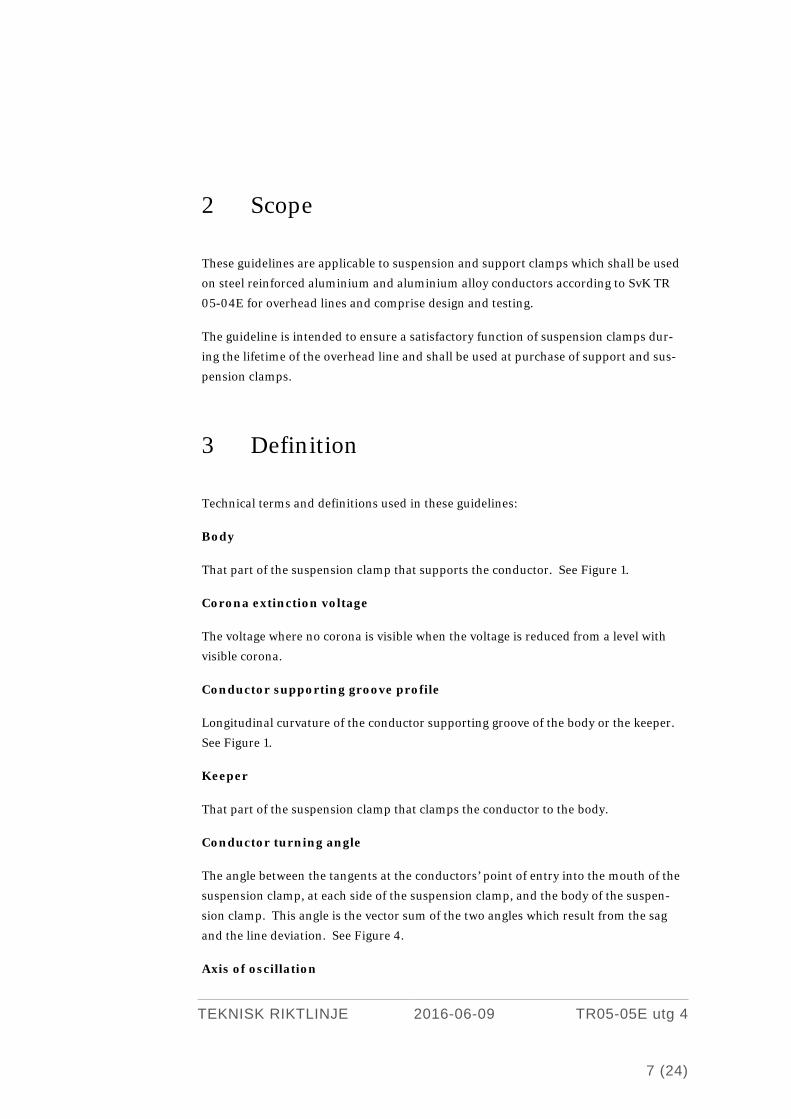
Body
That part of the suspension clamp that supports the conductor. See Figure 1.
Corona extinction voltage
The voltage where no corona is visible when the voltage is reduced from a level with
visible corona.
Conductor supporting groove profile
Longitudinal curvature of the conductor supporting groove of the body or the keeper.
See Figure 1.
Keeper
That part of the suspension clamp that clamps the conductor to the body.
Conductor turning angle
The angle between the tangents at the conductors’ point of entry into the mouth of the
suspension clamp, at each side of the suspension clamp, and the body of the suspen-
sion clamp. This angle is the vector sum of the two angles which result from the sag
and the line deviation. See Figure 4.
Axis of oscillation
TEKNISK RIKTLINJE 2016-06-09 TR05-05E utg 4
7 (24)
Axis around which clamp oscillations take place.
Straps
Those parts of the suspension clamp which transfer load from the axis of oscillation to
the connection point with the insulator string.
4 Description
4.1 Suspension clamp Suspension clamps shall have the axis of oscillation in the plane of the axis of the con-
ductor. They shall be used for both phase conductors and shield wires as well as for
straight line and angle supports. Suspension clamps shall be capable of being fitted
with counter weights.
4.2 Support clamp Support clamps shall have the axis of oscillation in the plane of the axis of the conduc-
tor. They shall be used for shield wires for straight line supports and shall be installed
in the supports shield wire bracket.
4.3 Counterweight stirrup Counterweight stirrups shall fit to the accompanying suspension clamp. They shall
transfer the load from the counterweight to the body of the suspension clamp. They
shall permit 45° of counterweight swing from the vertical plane in both directions.
Counterweight stirrups are also to be used with triple bundle conductors. See Figure
3.
5 Requirements
5.1 General In new built transmission lines shall the support clamp be installed in the supports
shield wire bracket. Adapter is not allowed.
Suspension clamps shall be able to withstand the mechanical stresses which can occur
during transport, handling and installation at temperatures as low as -40 °C, in addi-
tion to the mechanical stresses which can occur during the lifetime of the overhead line
at temperatures from -50 °C to +100 °C.
TEKNISK RIKTLINJE 2016-06-09 TR05-05E utg 4
8 (24)
5.2 Material
5.2.1 Body and keeper The body and the keeper shall be manufactured from aluminium alloy containing a
maximum of 0.10 % Cu. The alloy shall be resistant to inter-crystalline, layer and
stress corrosion. Further properties of the alloy shall be:
• Hardness min 75 HBW
• Resistivity max. 60 nΩm at 20 °C
5.2.2 Bolts and nuts Bolts and nuts shall be made from stainless steel which shall fulfil the requirements of
quality A2-80 according to SS-ISO 3506. The mechanical properties shall conform to
SS-EN ISO 3506-1 and SS-EN ISO 3506-2. U-bolts are not allowed.
5.2.3 Washers To provide sufficient resistance to corrosion washers shall be made from stainless steel
with a minimum quality equivalent to A2 of SS-EN ISO 3506. The washers shall be in
accordance with SS-EN ISO 887 and SS-EN ISO 7089. Washers shall have a minimum
hardness of 200 HBW
5.2.4 Threaded inserts To provide sufficient resistance to corrosion threaded inserts shall be made from stain-
less steel with a minimum quality equivalent to A2 of SS-EN ISO 3506. The required
mechanical properties shall be equivalent to those given for bolts and nuts in Clause
5.2.2.
5.2.5 Straps Straps shall be made from hot-dip galvanised steel. The thickness of the zinc coating
shall be at least 70 µm and meet the requirements according to SS-EN ISO 1461.
5.3 Design
5.3.1 Clamp It shall be possible to move clamps along the conductor freely. The trunnion of the
clamp may be an integral part of the body. If the trunnion is not an integral part it
shall be fixed by mechanical locking to the clamp body.
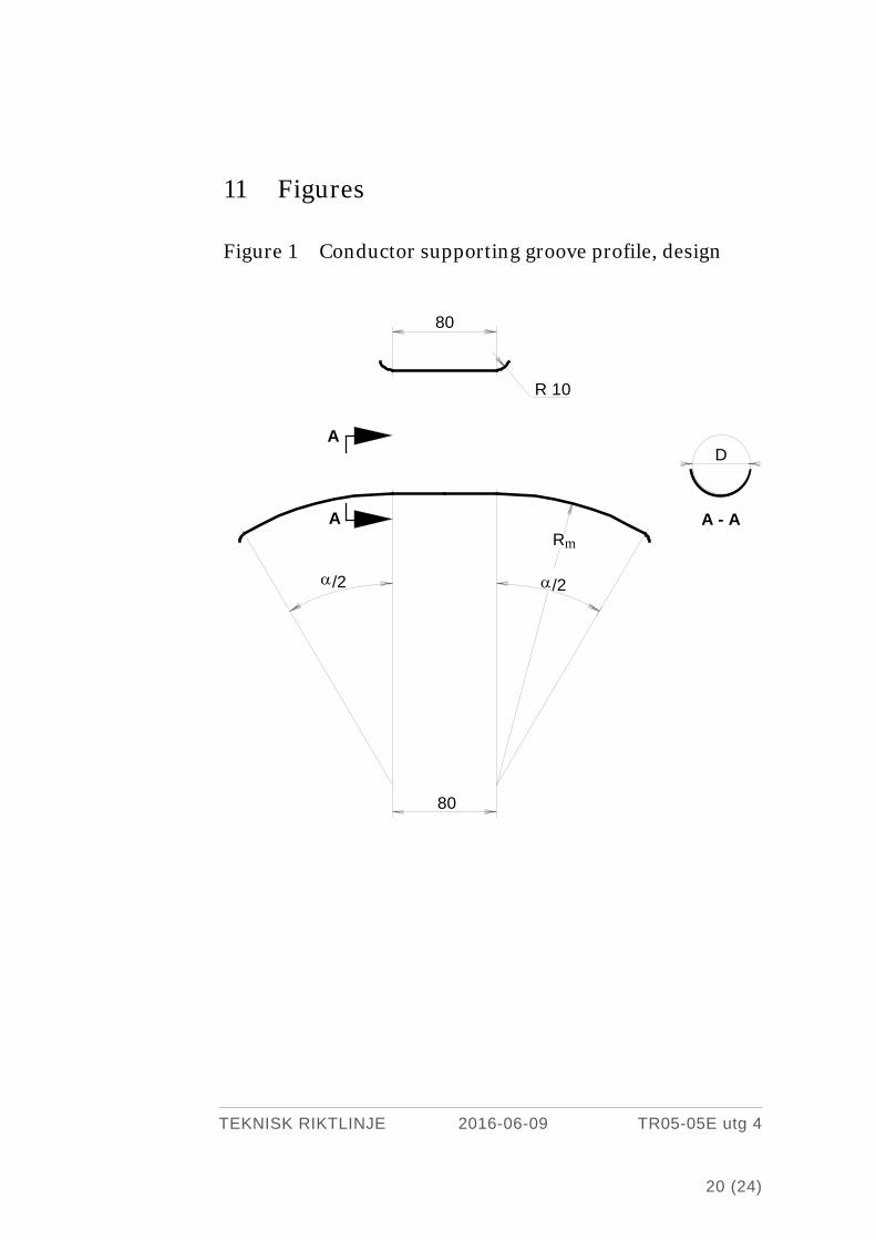
5.3.2 Conductor supporting groove The profile of the conductor supporting groove, in the body and the keeper, shall con-
form to the measurements given in Figure 1 and Table 1. The conductor groove radii
in body and keeper shall be adapted to the conductor diameter in question in accord-
ance with SvK TR 05-04E and with maximal groove diameter in accordance to Table 1
TEKNISK RIKTLINJE 2016-06-09 TR05-05E utg 4
9 (24)

and be free from irregularities and sharp edges. The straight part of the conductor
groove (80 mm) may be perpendicular furrowed with a maximum depth of 0,5 mm.
5.3.3 Fatigue damages Clamps may not cause fatigue damage on the conductor.
5.3.4 Straps The hole in the strap for the trunnion of the body shall be round and have a suitable
size in relation to the trunnion.
5.3.5 Bolts and nuts Bolts and nuts shall have M12 metric threads with 18 mm width across flats according
to SS-ISO 272. Bolts and nuts shall be attached to the tension clamp in such a way that
they are impossible to drop accidentally. It shall also be possible to tighten them from
the upper side of the clamp.
Bolts shall be long enough to protrude outside the thread of the nut. Counter bores
and countersinks shall be made in accordance with SS 2173.
Bolts and nuts shall be locked with two punches or other metallic locking system.
5.3.6 Washers Washers shall be manufactured in accordance with SS-EN ISO 887 and SS-EN ISO
7089.
5.3.7 Suspension clamps Suspension clamps shall have a clevis type coupling in accordance with TR 05-12E.
The distance from the axis of oscillation to the axis of the clevis coupling shall be as
short as possible
5.3.8 Support clamps Support clamps, will be installed on top of crossarms or earth wire peaks. Clamps with
brackets shall allow a minimum of 15° vertical movement in both directions without
causing contact between the conductor and crossarms or shield wire peaks.
5.3.9 Counterweight stirrups Counterweight stirrups shall fit to the accompanying suspension clamp. They shall be
so designed that the load of the counterweight is transferred to the body of the suspen-
sion clamp in accordance with Figure 2. Counterweight stirrups shall be able to swing
in line with the direction of the conductor. They shall also permit 45° of counterweight
swing from the vertical plane in both directions transverse to the direction of the con-
ductor. The distance (B) between the conductor and the link of the counterweight set
TEKNISK RIKTLINJE 2016-06-09 TR05-05E utg 4
10 (24)
shall be in accordance with Table 1. It shall be possible to install counterweight stir-
rups after suspension clamps have been installed.
Counterweight stirrups are also to be used with triple bundle conductors with yoke
plates. See Figure 3.
5.3.10 Marking Clamps shall be marked with raised or indented / stamped characters with a minimum
height of 3 mm as follows:
• Manufacturer’s trademark
• Type or catalogue number
• Conductor diameter
• Bolts and nuts to be marked in accordance with SS-EN ISO 3506.
• Year of manufacture.
5.4 Mechanical requirements
5.4.1 Suspension clamps for earth wire Suspension clamps shall, without showing signs of permanent deformation, withstand
the deformation load given in Table 1 at a conductor turning angle α of 30°. See Figure
4.
Suspension clamps shall, without failure at a conductor turning angle α of 30°, with-
stand the breaking load given in Table 1. See Figure 4.
Requirements for suspension clamps designed for 45° turning angle, see Appendix A.
5.4.2 Suspension clamps for phase conductor
Suspension clamps shall, without showing signs of permanent deformation, withstand
the deformation load given in Table 1 at a conductor turning α angle of 30°. See Figure
4.
Suspension clamps shall, without failure at a conductor turning angle α of 45°, with-
stand the breaking load given in Table 1. See Figure 4.
Requirements for suspension clamps designed for 45° turning angle, see Appendix A.
5.4.3 Support clamps for earth wire Support clamps shall, without showing signs of permanent deformation, withstand the
deformation load given in Table 1 at a conductor turning angle α of 30°. See Figure 4.
TEKNISK RIKTLINJE 2016-06-09 TR05-05E utg 4
11 (24)
Support clamps shall, without failure, at a conductor turning angle α of 30° withstand
the breaking load given in Table 1. See Figure 4.
5.4.4 Clamps Clamps shall, without showing signs of permanent deformation, withstand the tighten-
ing torque of the bolts.
5.4.5 Clamping force The clamp force induced by the bolts shall, for suspension clamps for phase conduc-
tors, be at least 112 kN when tightened to a torque of 60 Nm and, for suspension and
support clamps for earth wire, be at least 64 kN when tightened to a torque of 37 Nm.
5.4.6 Bolts and threads Bolts and threads of clamps shall, without rupture, withstand an axial load of 67 kN.
5.4.7 Counterweight stirrups Counterweight stirrups shall, without showing signs of permanent deformation, with-
stand the deformation load given in Table 1. See Figure 5.
5.5 Electrical requirements
5.5.1 Fault current Suspension clamps and support clamps shall withstand the fault current given in Table
1 at a mechanical load of 3 kN. The peak value of the fault current shall be a minimum
of 2,3 times its effective value.
5.5.2 Corona Suspension clamps which will be used for the suspension of phase conductors shall,
when fitted to an insulator set, conform to the requirements of SvK TR 05-10E Clause
5.4.4.
5.5.3 Hysteresis losses Suspension clamps which shall be used for the suspension of phase conductors shall
cause no hysteresis losses.
Counterweight stirrups installed on phase conductor suspension clamps shall cause no
hysteresis losses.
TEKNISK RIKTLINJE 2016-06-09 TR05-05E utg 4
12 (24)
6 Type test
6.1 General Unless otherwise agreed upon the type test shall be in accordance with Clauses 6.2-
6.10 on three test samples. The test shall be performed in such a way that the method
and equipment do not affect the result.
6.2 Dimensions This test intends to check that the clamp and the counterweight stirrup fulfil the re-
quirements in accordance with Clause 5.3 and that they are also in accordance with the
manufacturers drawing regarding dimensions.
6.3 Thickness of zinc coating This test shall be performed in accordance with SS-ISO 2178. Each sample shall be
subject to, depending on size, 3 to 10 measurements. The points of measurement shall
be evenly and randomly distributed over the entire sample surface.
The minimum and average layer thickness requirements in accordance with Clause
5.1.5 shall be fulfilled.
6.4 Hardness Hardness tests on aluminium shall be in accordance with SS-EN ISO 6506-1.
Measured hardness value shall conform to the requirements of Clause 5.2.1.
6.5 Clamping force The clamp force shall be measured with one or two load cells located in the conductor
supporting groove during a sequence of three installations. The bolts shall be tight-
ened with a torque of 60 Nm at suspension clams for phase conductors and with 37
Nm for clamps for earth wires.
The measured clamp force shall during all three installations exceed the requirements
of Clause 5.4.6.
6.6 Threads Securing bolts shall be installed in threads to a length equivalent to the minimum
length as specified on the workshop drawings. A tensile load of 67 kN shall be applied
to the bolt.
Rupture shall not have occurred in the threads and the bolt shall be easily turned by
hand.
TEKNISK RIKTLINJE 2016-06-09 TR05-05E utg 4
13 (24)

6.7 Permanent deformation
6.7.1 Suspension and support clamp The clamp shall be installed on conductors with the required strength and same diam-
eter as the conductor for which the clamp is designed. The securing bolts shall be
tightened with a torque of 60 Nm at clamps for phase conductors respectively with 37
Nm at clamps for earth wires.
The clamp shall be installed in a tensile testing machine in such a way that the conduc-
tor turning angle α, conforms to Table 1 during the test. See Figure 4. The load shall
be increased in steps. The first step shall be 10 % of the specified deformation load.
The clamp shall then be unloaded and measurement of the permanent deformation, if
any, carried out and recorded. The second step shall be 20 % of the specified defor-
mation load. The clamp shall then be unloaded and measurement of the permanent
deformation, if any, carried out and recorded. This procedure shall be continued until
100 % of the specified deformation load is attained.
The load at which permanent deformation is shown shall exceed the load given in Ta-
ble 1 in accordance with Clauses 5.4.1 and 5.4.2.
6.7.2 Counterweight stirrup The counterweight stirrup shall be attached to a suspension clamp, or a dummy, in
accordance with the installation instructions.
The counterweight stirrup is then to be installed in a tensile testing machine. See Fig-
ure 5. The load shall be increased in steps. The first step shall be 10 % of the specified
deformation load. The stirrup shall then be unloaded and measurement of the perma-
nent deformation, if any, carried out and recorded. The second step shall be 20 % of
the specified deformation load. The stirrup shall then be unloaded and measurement
of the permanent deformation, if any, carried out and recorded. This procedure shall
be continued until 100 % of the specified deformation load is attained.
The load at which permanent deformation is shown shall exceed the load given in Ta-
ble 1 in accordance with Clause 5.4.7.
6.8 Breaking load After the clamp has been tested in accordance with Clause 6.7.1 the load shall be in-
creased until failure occurs in the clamp.
The attained breaking load shall exceed the load given in Table 1 in accordance with
Clauses 5.4.1, 5.4.2 and 5.4.3.
TEKNISK RIKTLINJE 2016-06-09 TR05-05E utg 4
14 (24)

6.9 Corona The intention of this test is to verify the corona extinction voltage in a fully assembled
insulator set.
The test shall be performed in accordance with SvK TR 05-10E Clause 6.5.
6.10 Fault current The intention of this test is to verify that the requirements in Clause 5.5.1 are fulfilled.
Test performed on other product consisting of the same materials and having equal
contact surfaces is considered to constitute type test for clamps in accordance with this
guidelines.
7 Sample test
7.1 General Sample tests are carried out by the manufacturer on clamps selected at random from
the lot to be supplied.
Test samples shall be supplied by the manufacturer free of charge to the client and
shall not be included in the lot to be supplied.
The size of the test samples are indicated in the table below.
Lot size Sample size
N ≤ 300 1 to 3 subject to agreement
300 < N ≤ 2000 4
2000 < N ≤ 5000 8
5000 < N ≤ 10000 12
The samples shall be subject to testing in accordance with Clauses 7.2 to 7.6. Clamps
which have been submitted for test shall be discarded.
The manufacture shall inform the client when sample tests will be made.
TEKNISK RIKTLINJE 2016-06-09 TR05-05E utg 4
15 (24)
Records from the sample tests shall be filed by the manufacturer and be shown to the
client on request. In the case where any component does not comply with the re-
quirements, re-testing shall be performed as below.
If only one clamp or part thereof fails to comply with the sample test requirement, a
new sample equal to twice the quantity originally submitted for that test shall be sub-
ject to re-testing. The re-testing shall comprise the test or tests in which failure oc-
curred.
If two or more clamps, or parts thereof, fail to comply with any of the sample tests, or
if any failure occurs during re-testing, the complete lot shall be considered not to com-
ply with the requirements.
Provided that the cause of the failure can be clearly identified, the manufacturer may
sort the lot to eliminate all the clamps with this defect. The sorted lot shall then be
resubmitted for sample testing. The number then selected shall be three times the first
quantity chosen for the test. The re-testing shall comprise the test or tests in which
failure occurred in the original test.
If any clamp, or part thereof of the sorted lot, fails during this re-testing, the complete
lot shall be considered as not complying with the requirements.
7.2 Dimensions The test shall be performed in accordance with Clause 6.2.
7.3 Thickness of zinc coating The test shall be performed in accordance with Clause 6.3.
7.4 Hardness The test shall be performed in accordance with Clause 6.4
7.5 Clamping force The test shall be performed in accordance with Clause 6.5.
7.6 Threads The test shall be performed in accordance with Clause 6.6.
TEKNISK RIKTLINJE 2016-06-09 TR05-05E utg 4
16 (24)

8 Delivery
8.1 General The client shall, according to these guidelines, approve the clamp before delivery. For
approval the manufacturer shall show that the clamp conforms to the guidelines.
The manufacturer shall provide documentation in accordance with Clauses 8.2.1 to
8.2.7 inclusive for approval.
The approval of drawings by the client does not release the manufacturer from his
obligations regarding the clamp complying with the guidelines.
All documentation shall be written in Swedish or English.
8.2 Documentation General requirements for documentation see SvK TR 08E.
8.2.1 Assembly drawing The assembly drawing shall have a minimum of two views at an appropriate scale in
accordance with SS-ISO 5455. On the drawing shall be given:
• Type and/or catalogue number
• Principal dimensions
• The dimensions of the conductor groove with tolerances
• All marking.
• Weight.
• List of materials.
• Assembly instruction
8.2.2 List of material Description of material in included parts.
8.2.3 Manufacturing process Description of the manufacturing process
8.2.4 Quality system Quality system in accordance with SS-EN ISO 9001.
TEKNISK RIKTLINJE 2016-06-09 TR05-05E utg 4
17 (24)

8.2.5 Installation instructions Installation instructions shall be written in Swedish or English and include necessary
figures.
8.2.6 Fault current Test report verifying the compliance of the clamp regarding the fault current require-
ment as given in Clause 5.5.1
8.2.7 Reports Reports in accordance with Clause 6 Type test report and 7 Sample test report.
8.3 Sample
8.3.1 Clamp One clamp sample.
8.3.2 Counterweight stirrup One stirrup sample.
8.4 Transport and storing The suspension and support clamps shall be packed up in that way that they will not be
damaged or fouled at transport, construction and storing.
9 Installation
Installation on the conductor and locking of bolts and nuts hall be performed in ac-
cordance with the manufacturers installation instructions.
TEKNISK RIKTLINJE 2016-06-09 TR05-05E utg 4
18 (24)
10 Tables
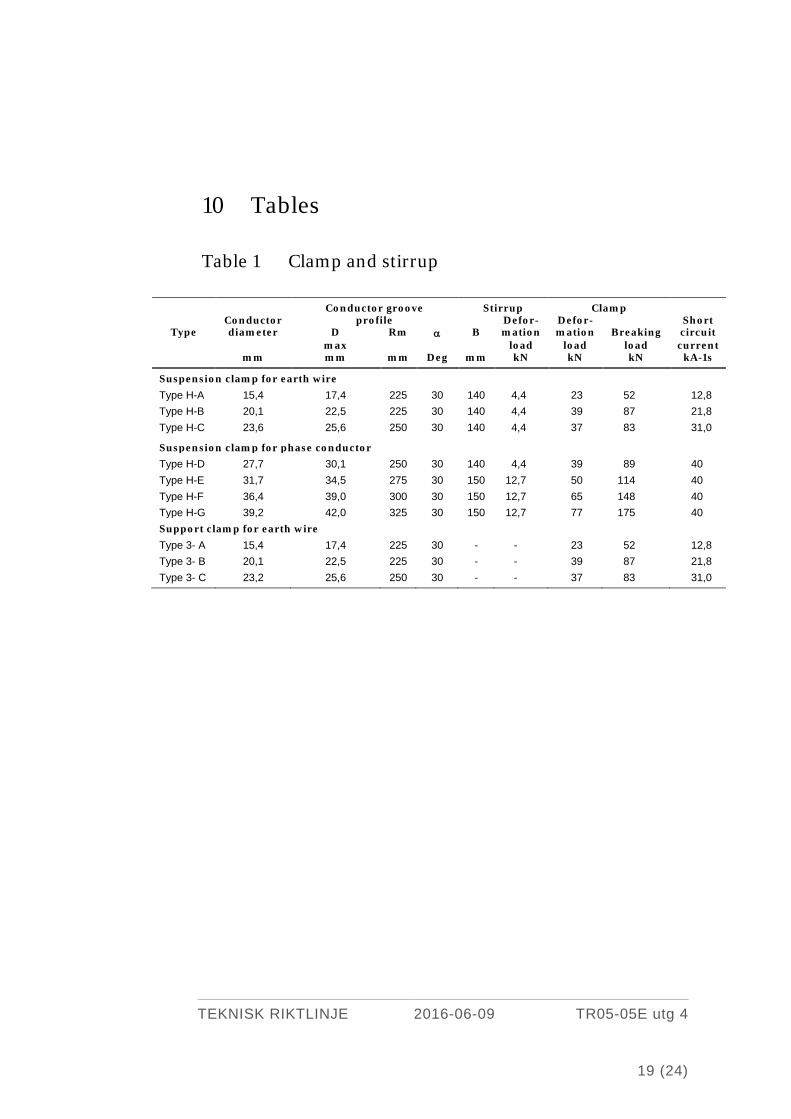
Table 1 Clamp and stirrup
Conductor groove Stirrup Clamp Conductor profile Defor- Defor- Short
Type diameter D Rm α B mation mation Breaking circuit max load load load current mm mm mm Deg mm kN kN kN kA-1s
Suspension clamp for earth wire Type H-A 15,4 17,4 225 30 140 4,4 23 52 12,8 Type H-B 20,1 22,5 225 30 140 4,4 39 87 21,8 Type H-C 23,6 25,6 250 30 140 4,4 37 83 31,0
Suspension clamp for phase conductor Type H-D 27,7 30,1 250 30 140 4,4 39 89 40 Type H-E 31,7 34,5 275 30 150 12,7 50 114 40 Type H-F 36,4 39,0 300 30 150 12,7 65 148 40 Type H-G 39,2 42,0 325 30 150 12,7 77 175 40 Support clamp for earth wire Type 3- A 15,4 17,4 225 30 - - 23 52 12,8 Type 3- B 20,1 22,5 225 30 - - 39 87 21,8 Type 3- C 23,2 25,6 250 30 - - 37 83 31,0
TEKNISK RIKTLINJE 2016-06-09 TR05-05E utg 4
19 (24)
11 Figures
Figure 1 Conductor supporting groove profile, design
80
R 10
α
Rm
80
/2α/2
DA
A A - A
TEKNISK RIKTLINJE 2016-06-09 TR05-05E utg 4
20 (24)

Figure 2 Counterweight stirrup, dimensions
R 25
φ
B±5
40±1
22
A
A
A - A
TEKNISK RIKTLINJE 2016-06-09 TR05-05E utg 4
21 (24)
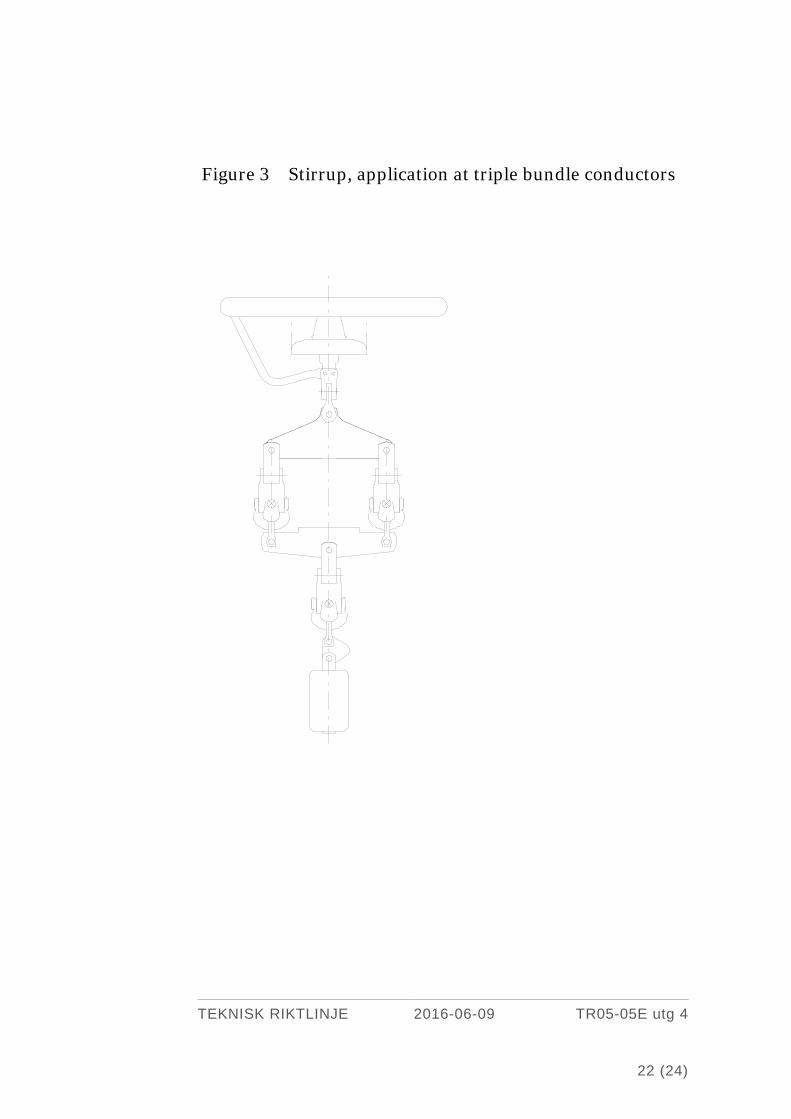
Figure 3 Stirrup, application at triple bundle conductors
TEKNISK RIKTLINJE 2016-06-09 TR05-05E utg 4
22 (24)

Figure 4 Clamp, arrangement for test of de-formation and breaking loads
α
F
Figure 5 Stirrup, arrangement for test of de-formation load
F
TEKNISK RIKTLINJE 2016-06-09 TR05-05E utg 4
23 (24)

12 Appendix A (Informative)
The requirements in this informative appendix are for suspension clamps intended for turning angles up to 45°.
12.A.1 Mechanical requirements for 45° turning angle
12 A.1.1 Suspension clamp for earth wire Suspension clamps shall, without showing signs of permanent deformation, withstand the deformation load given in Table 1 at a conductor turning angle α of 45°. See Figure 4. Suspension clamps shall, without failure at a conductor turning angle α of 45°, with-stand the breaking load given in Table 1. See Figure 4.
12.A.1.2 Suspension clamp for phase conductor Suspension clamps shall, without showing signs of permanent deformation, withstand the deformation load given in Table 1 at a conductor turning α angle of 45°. See Figure 4.
Suspension clamps shall, without failure at a conductor turning angle α of 45°, with-
stand the breaking load given in Table 1. See Figure 4.
Table 12.A.1 Clamp and stirrup
Conductor groove Stirrup Suspension clamp Conductor profile Defor- Defor- Short
Type diameter D Rm α B mation mation Breaking- circuit- max load load load current mm mm mm Deg mm kN kN kN kA-1s
Suspension clamp for earth wire Type H-A 15,4 17,4 225 45 140 4,4 34 76 12,8 Type H-B 20,1 22,5 225 45 140 4,4 57 129 21,8 Type H-C 23,6 25,6 250 45 140 4,4 54 123 31,0
Suspension clamp for phase conductor Type H-D 27,7 30,1 250 45 140 4,4 58 131 40 Type H-E 31,7 34,5 275 45 150 12,7 74 168 40 Type H-F 36,4 39,0 300 45 150 12,7 97 219 40 Type H-G 39,2 42,0 325 45 150 12,7 114 259 40
TEKNISK RIKTLINJE 2016-06-09 TR05-05E utg 4
24 (24)